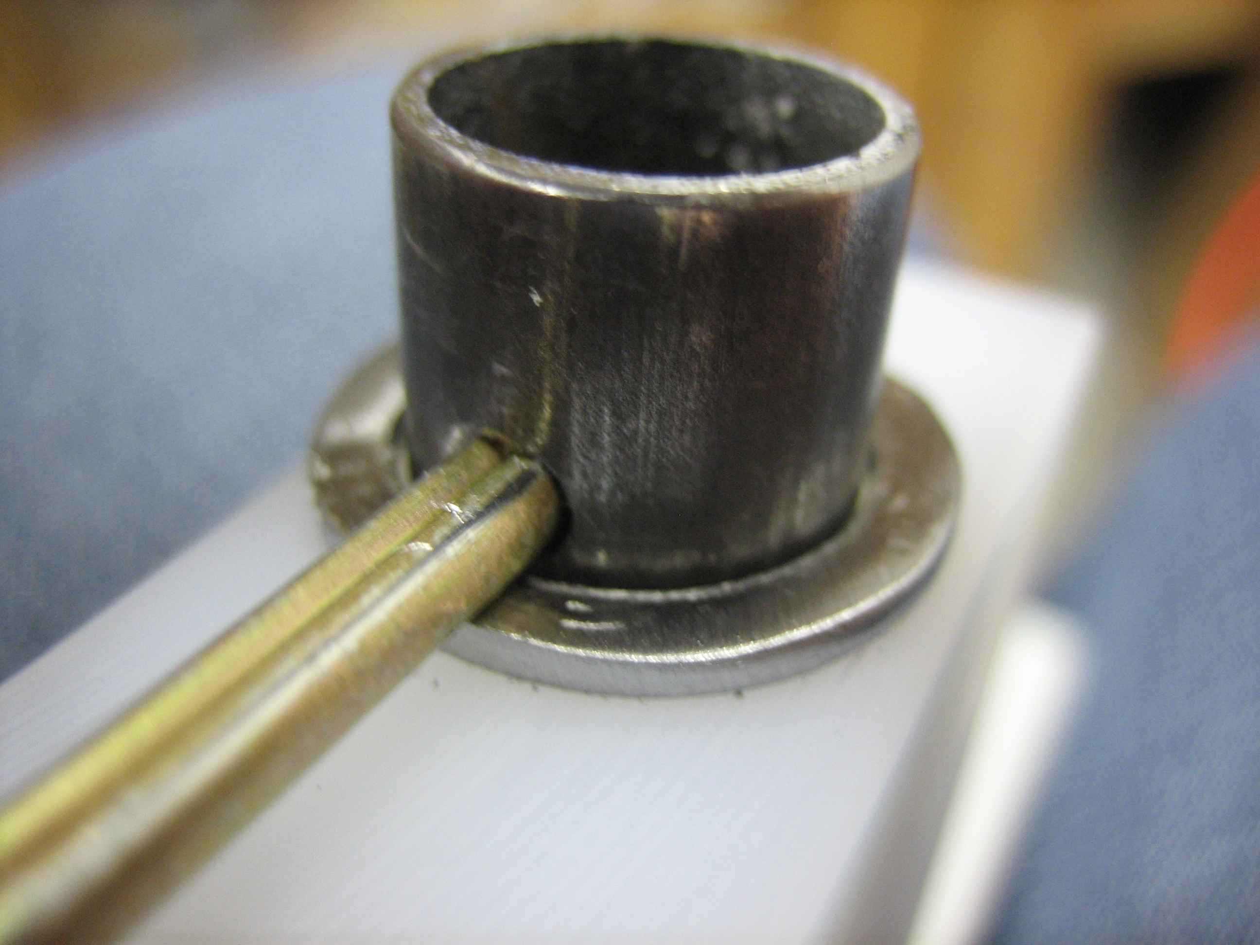
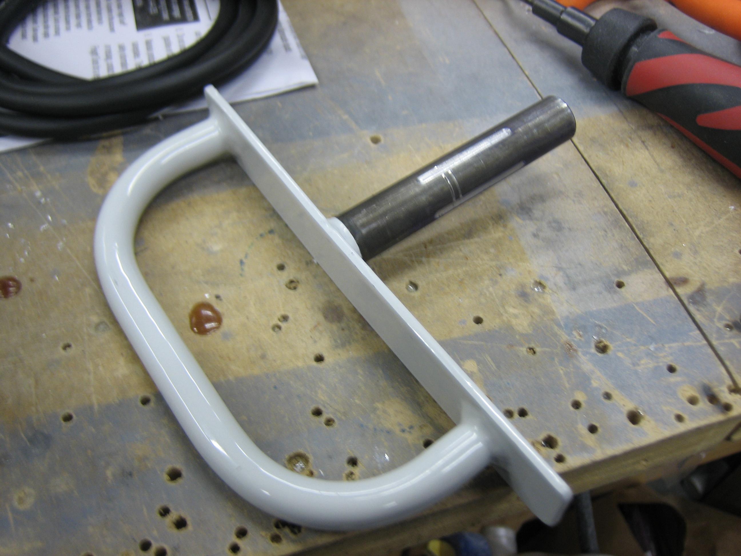
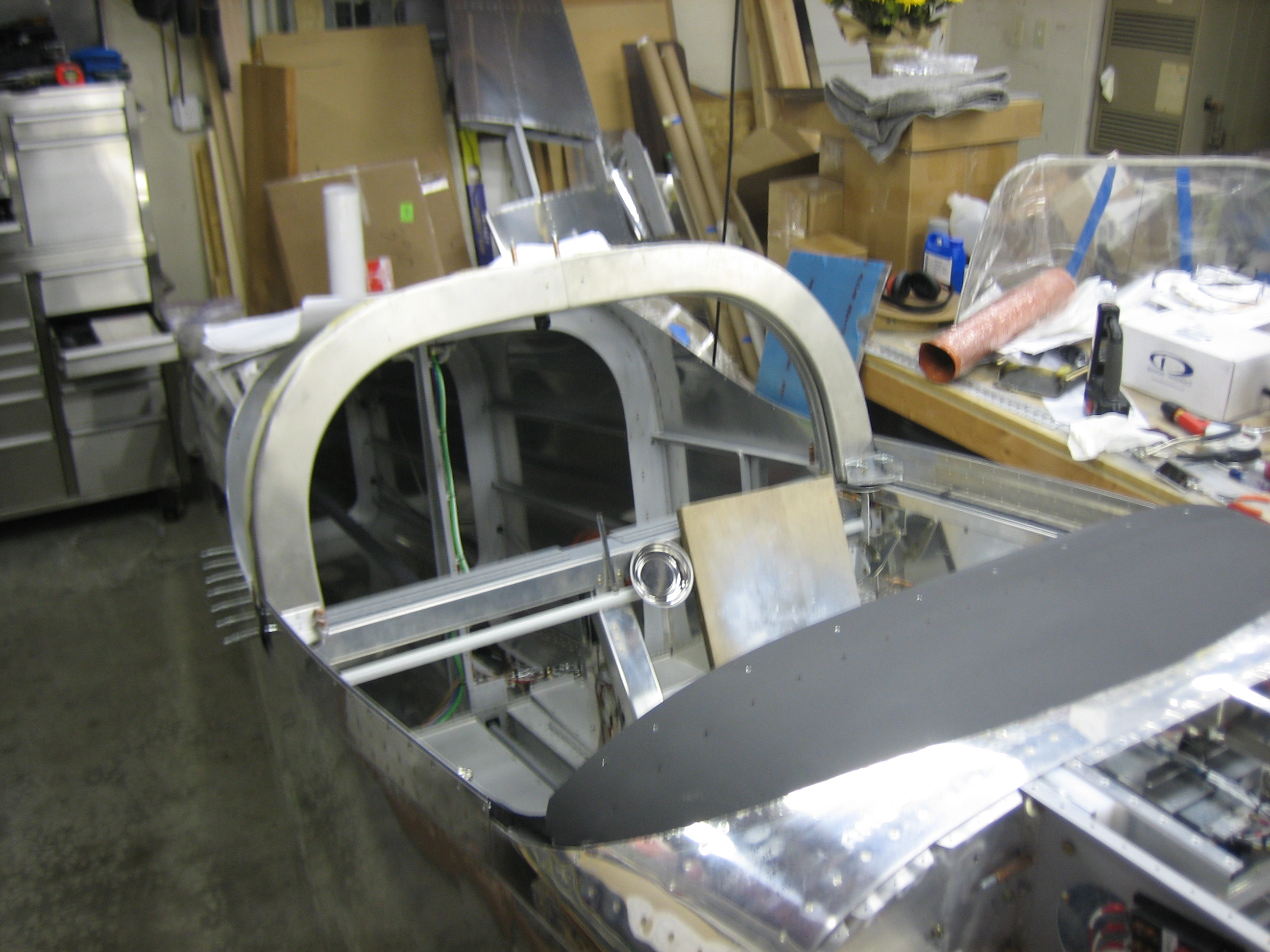
The canopy safety latch pivots in a UHMW block and is used as a secondary latch in case the primary canopy latches pop open. It’s also used to prop the canopy open by resting the longer flange on top of the roll bar. The problem is that because the latch is free to rotate, vibration can cause it to spin around and not stay where you put it. Worse, there has been at least one case where someone shut their canopy and the safety latch pivoted and caught under the roll bar, preventing them from opening the canopy. There are a couple of approaches that builders have used to prevent this. One is to simply squeeze the tube that passes through the UHMW block too increase the friction. Another is to allow the safety latch to slide up and down in the UHMW block with a spring to keep it up. The pilot would then need to pull it down to pivot it under the roll bar. For various reasons, I didn’t like either of these approaches. I ended up deciding to modify the latch so that there are detents when rotating (one in each of the latched and unlatched positions). I stopped by the TechShop and used their milling machine to machine some grooves into the shaft.

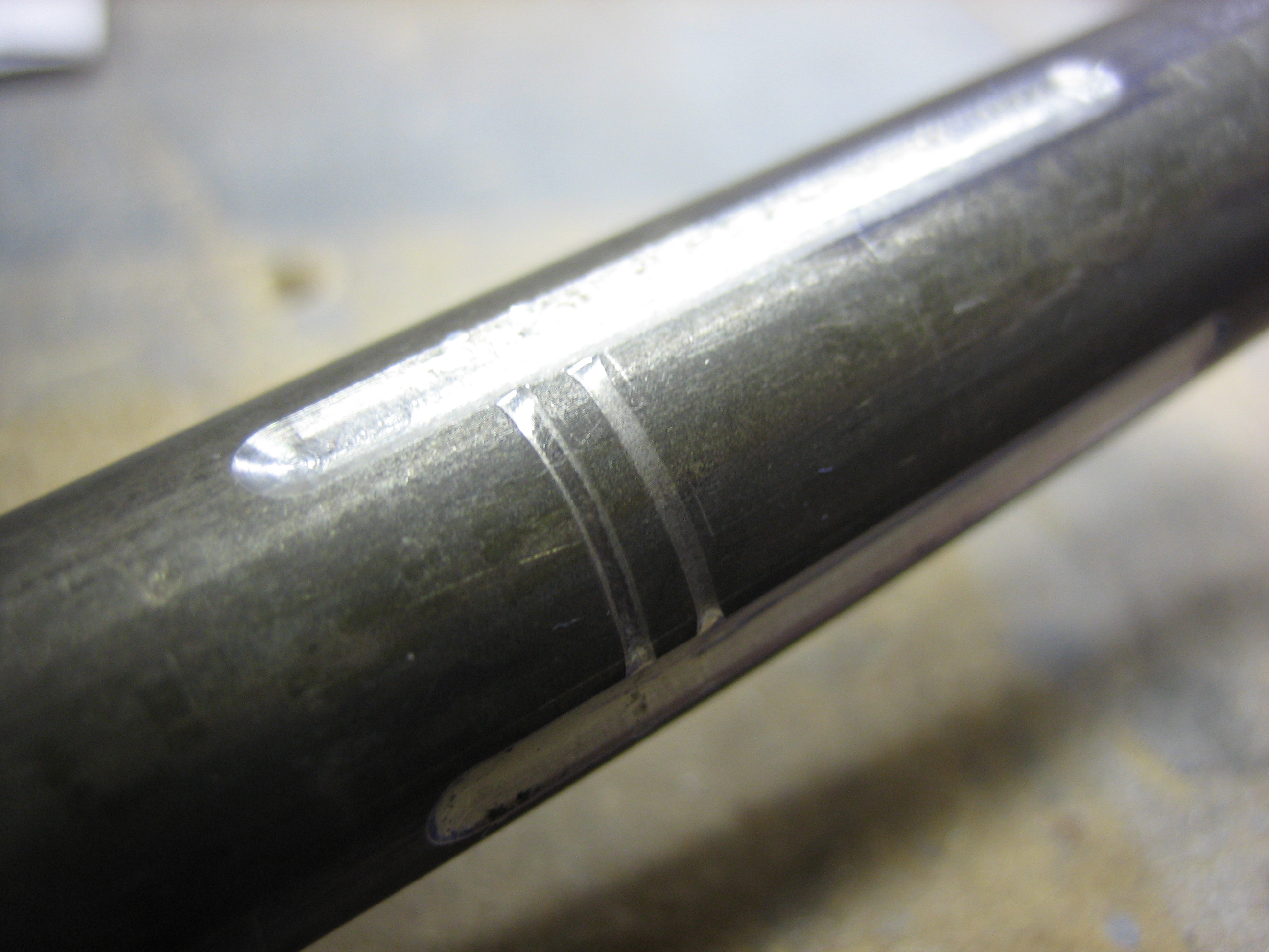
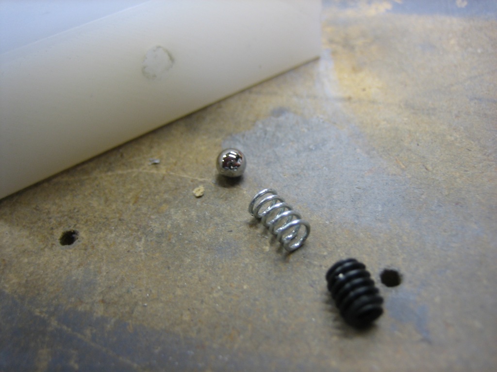
I used a 3/16″ diameter ball end mill to machine some grooves 0.030″ deep in the shaft 90º apart.

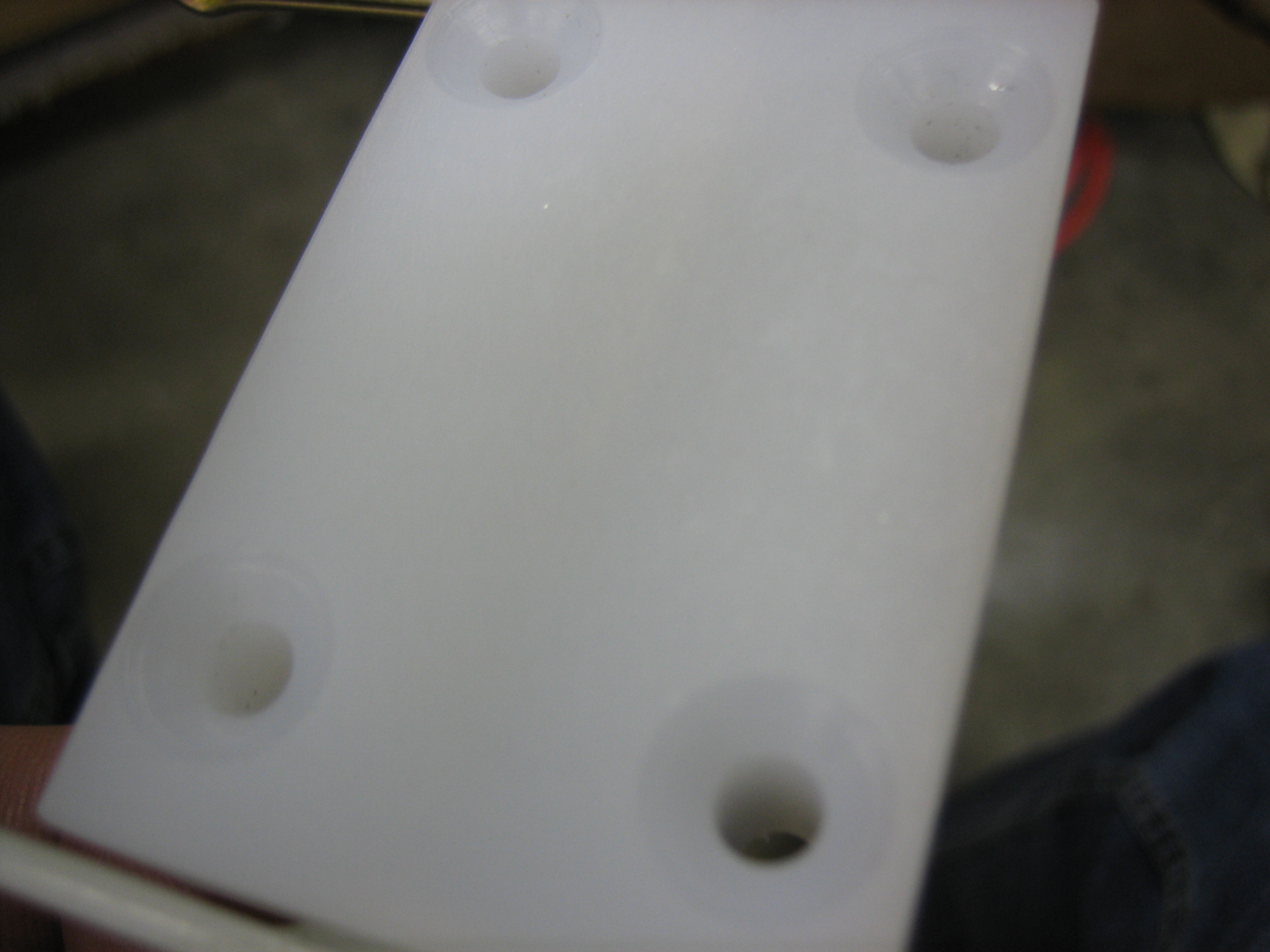
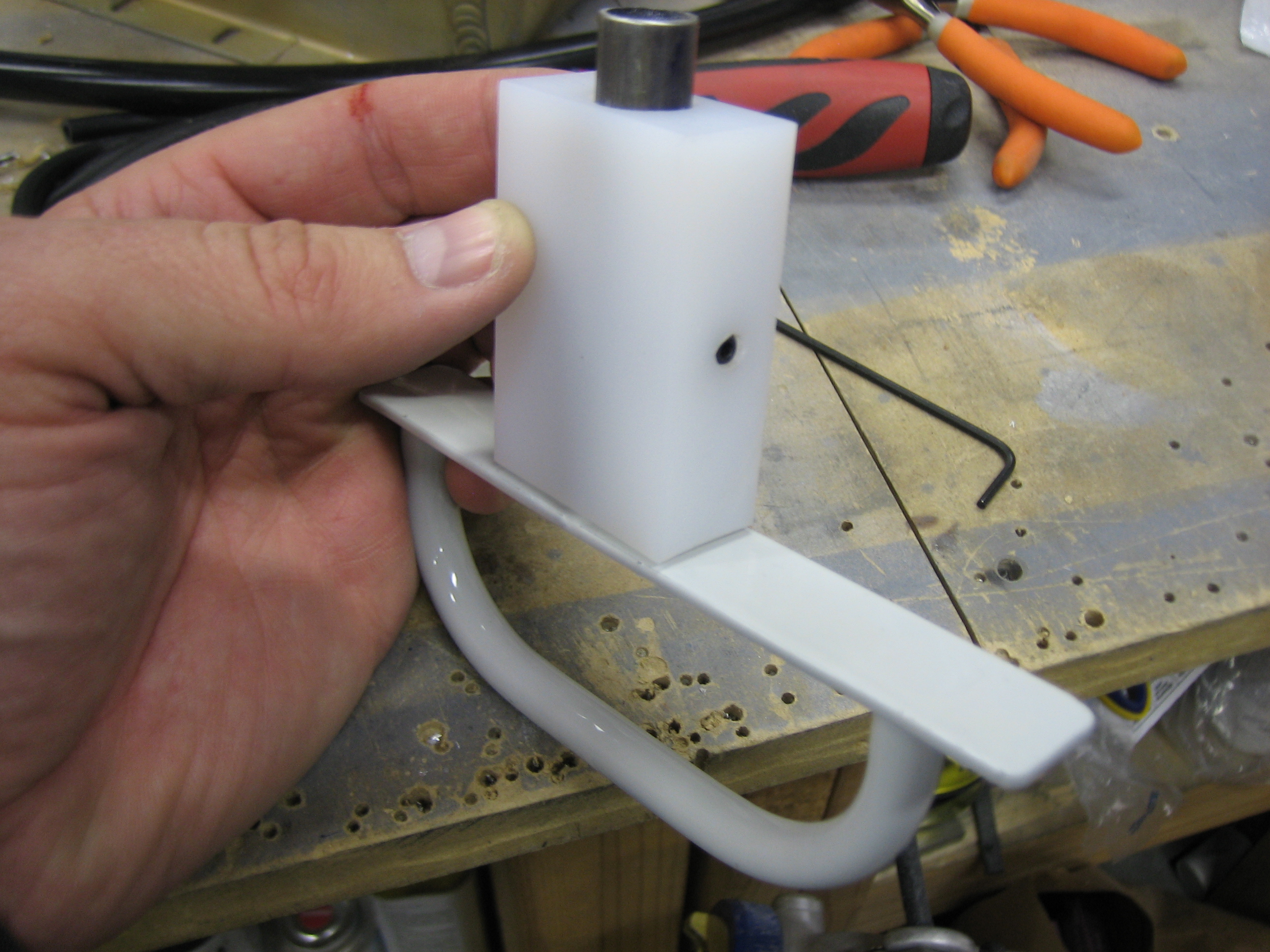
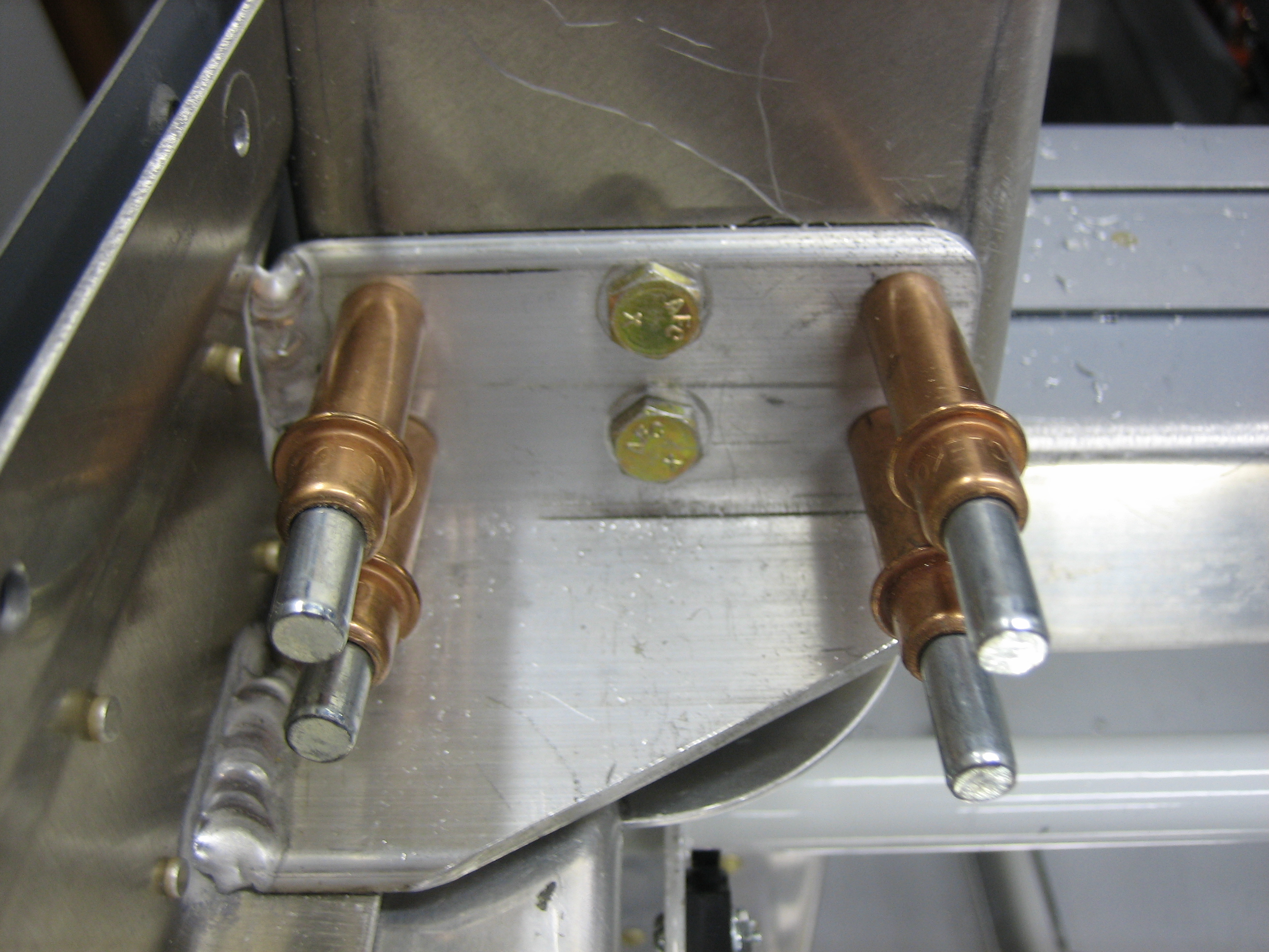
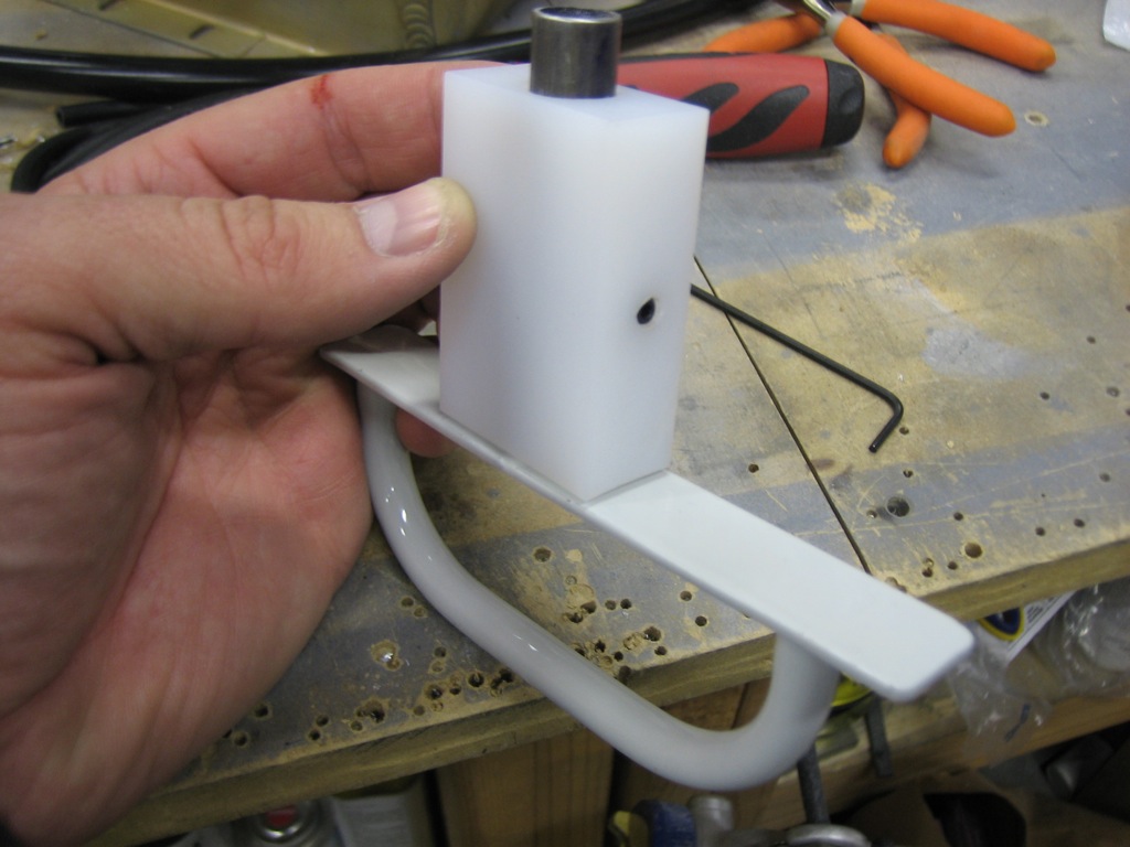
I then drilled a hole in the side of the UHMW block in line with the center of the shaft. The hole contains a 3/16″ ball bearing, a spring, and a set screw to adjust the pressure on the spring.
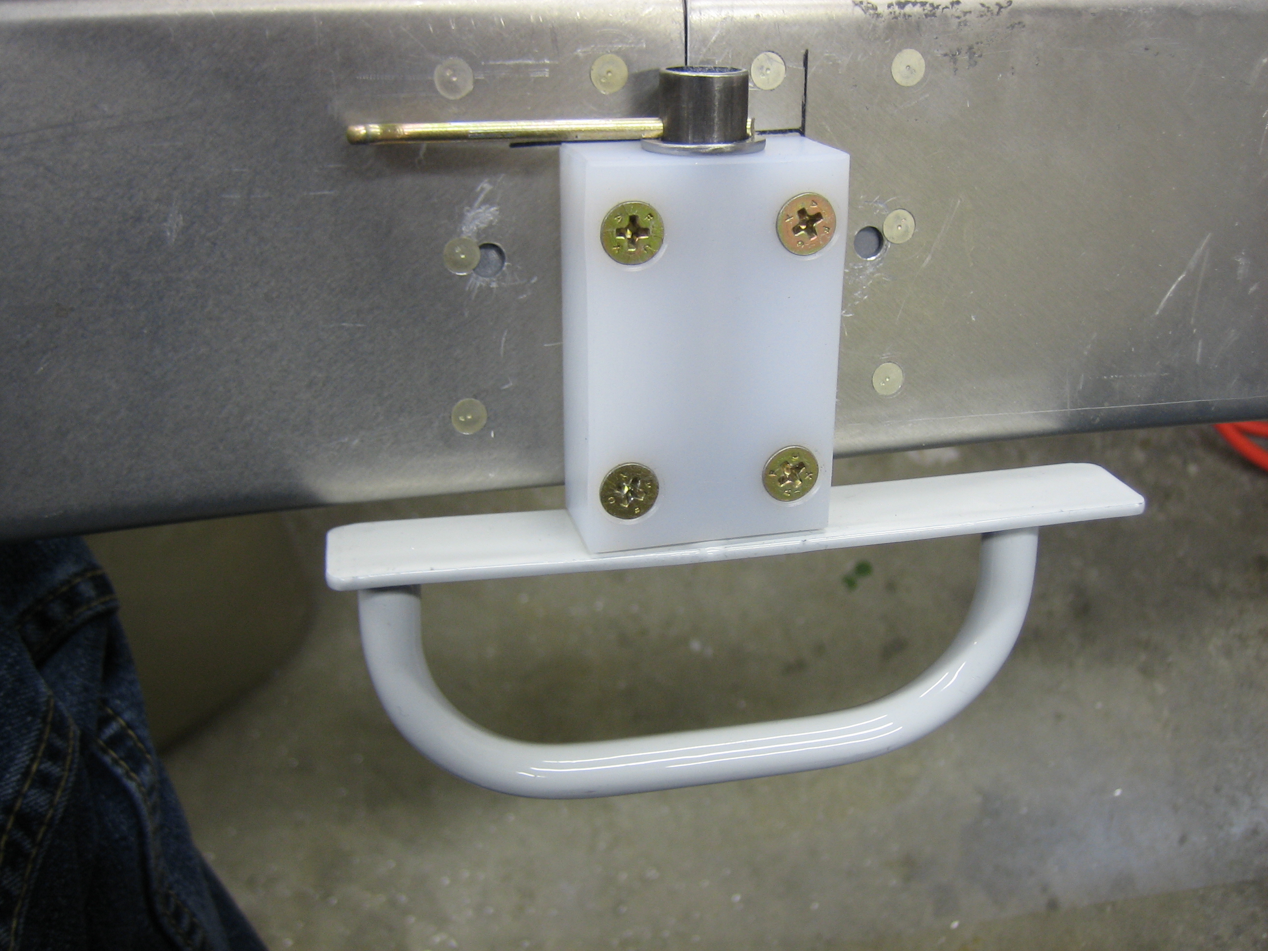
This works beautifully. The handle positively stops in the unlocked position (parallel to the block).
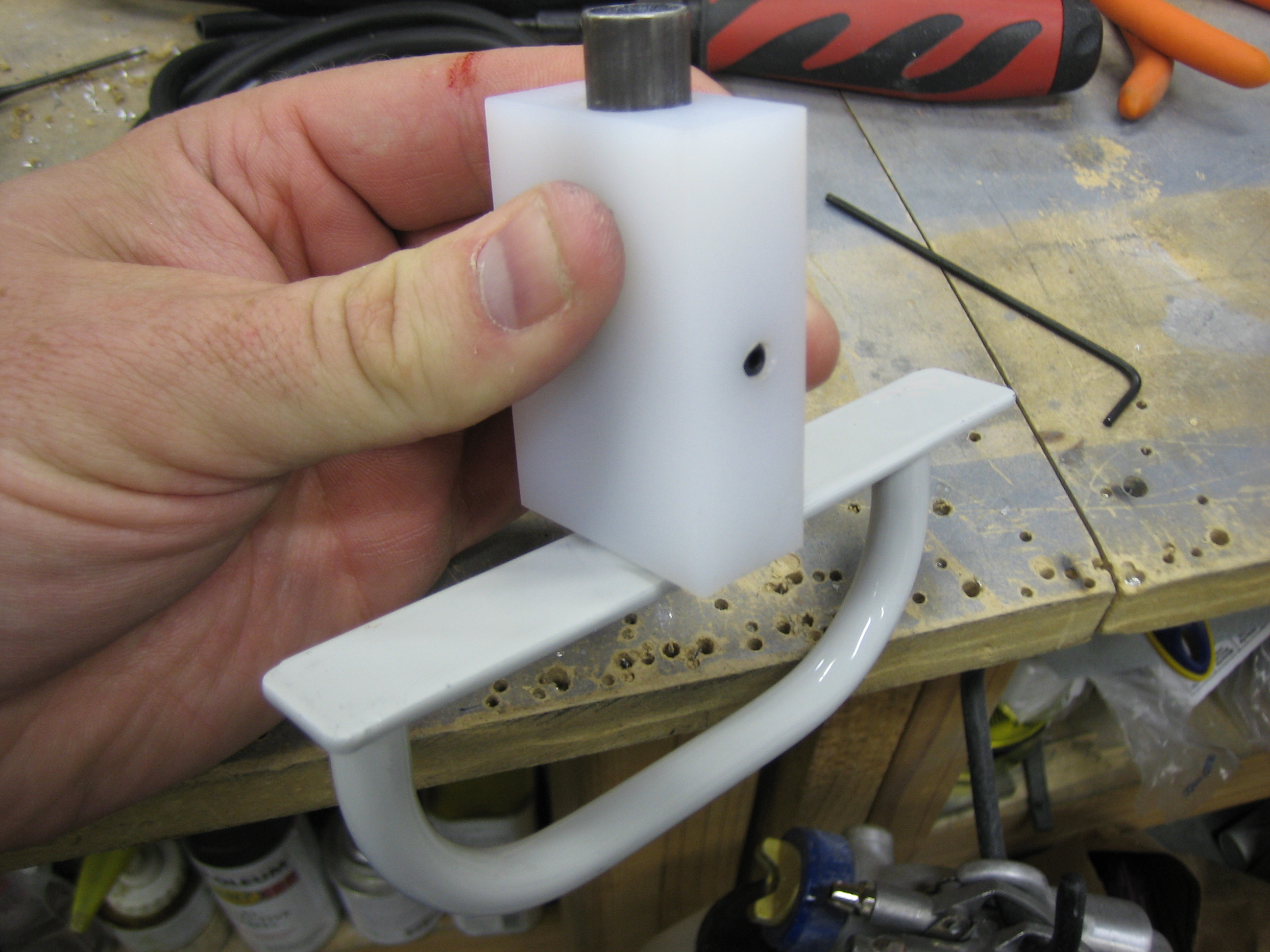
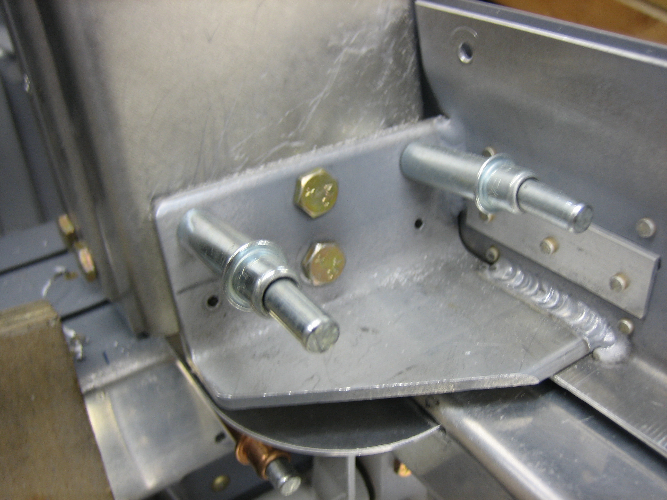
…and in the locked position (perpendicular to the block). I’m very happy with how this turned out.