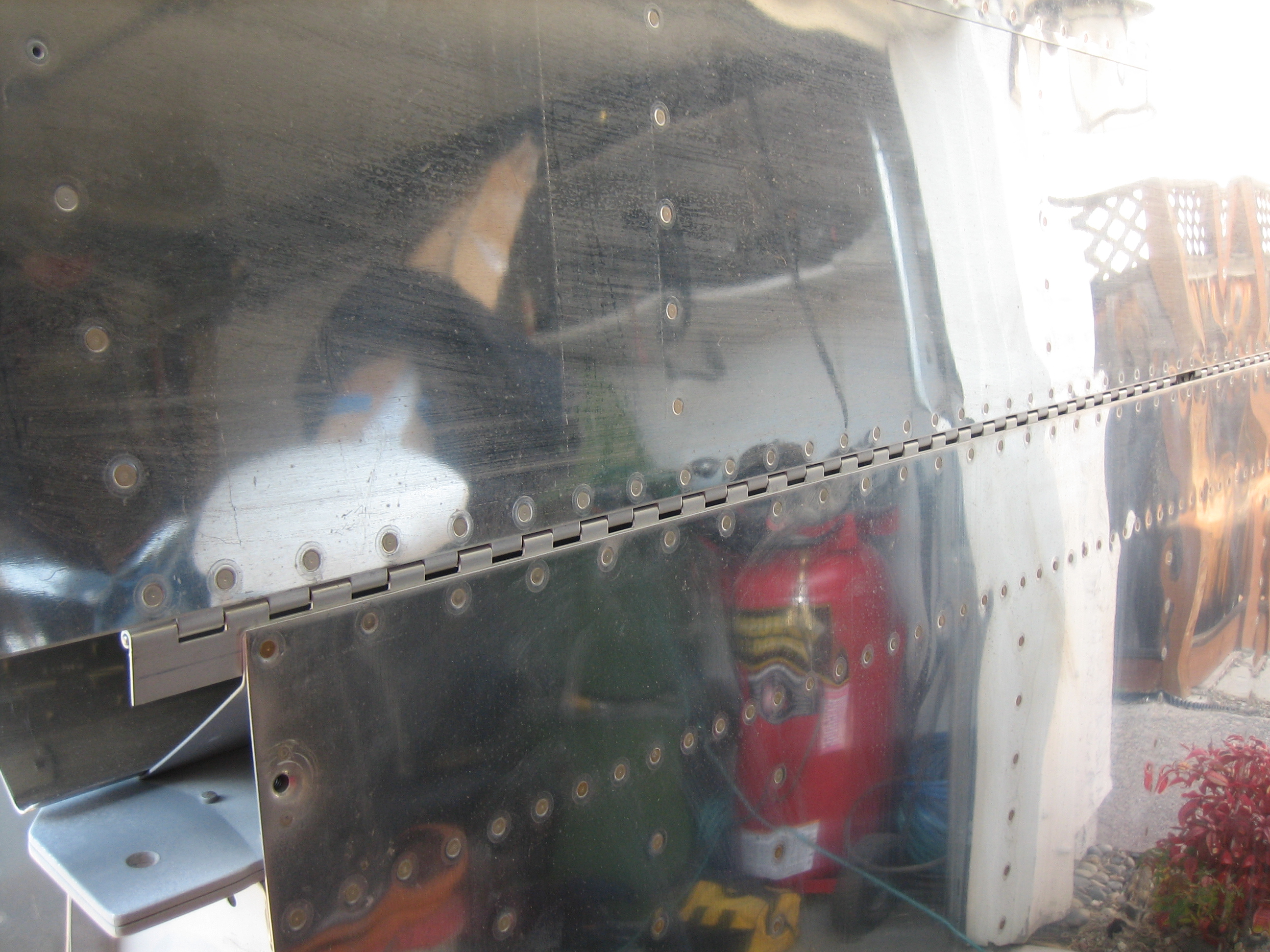
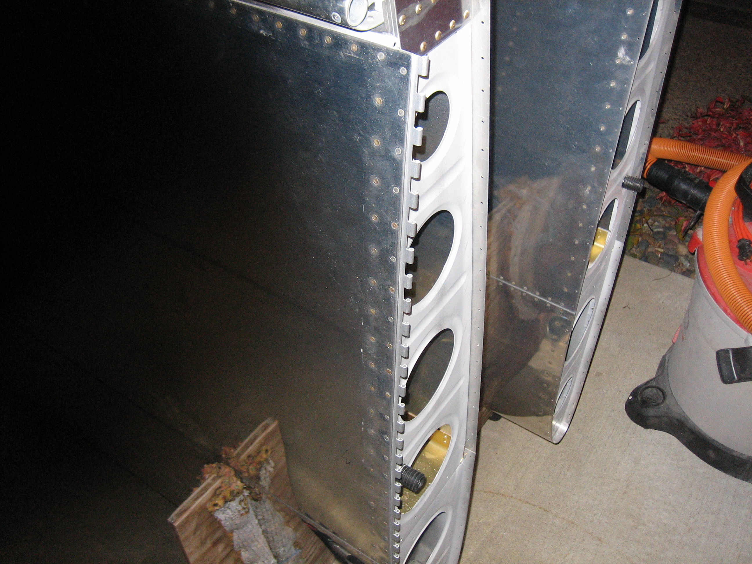
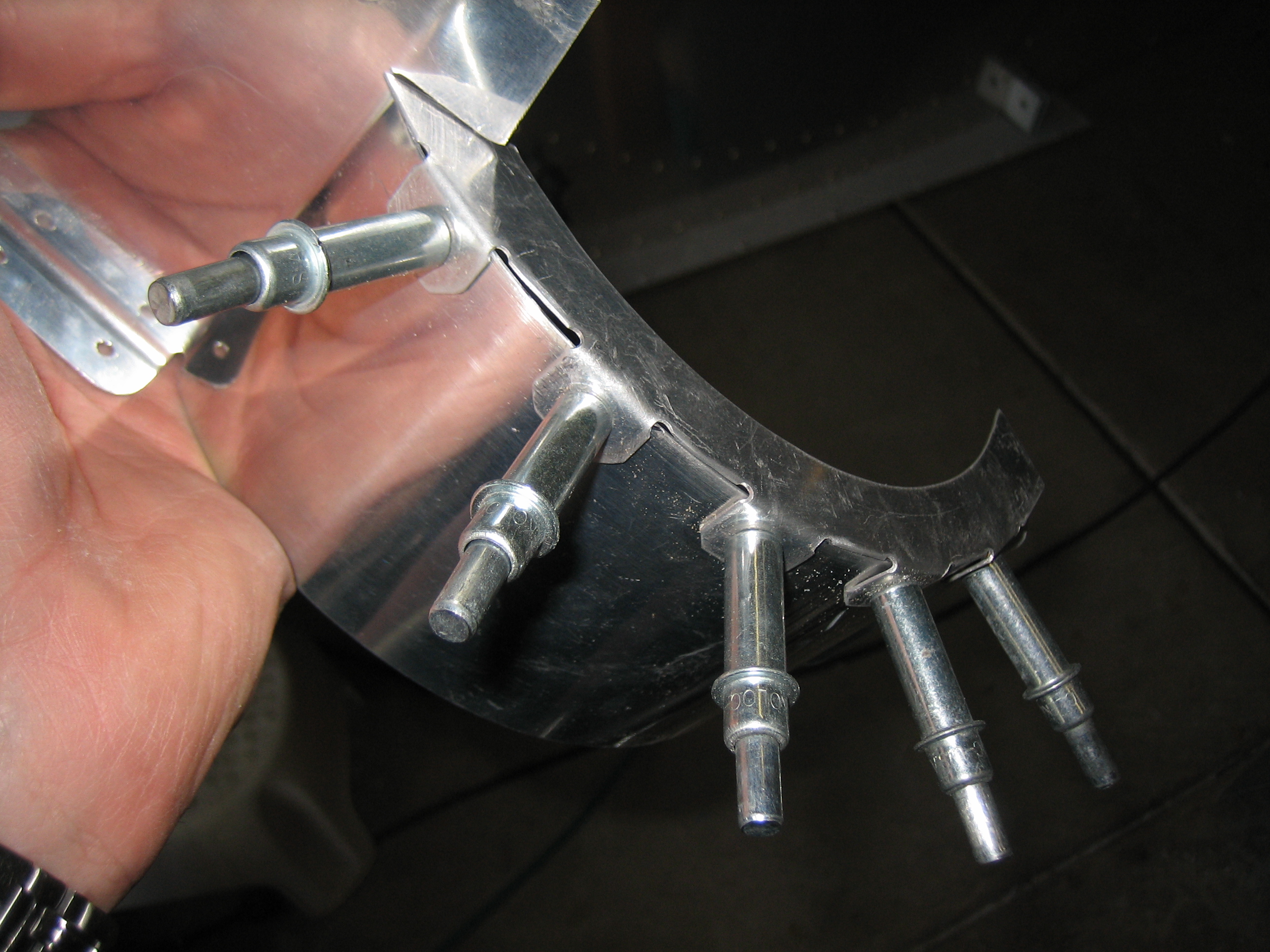
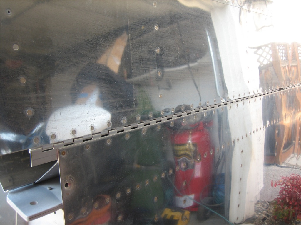
I finally riveted on the flap hinge. This has been on my to do list for weeks now, but the wings are mostly stored under a tarp beside my house, so I have to pull them around to the driveway every time I want to work on them.
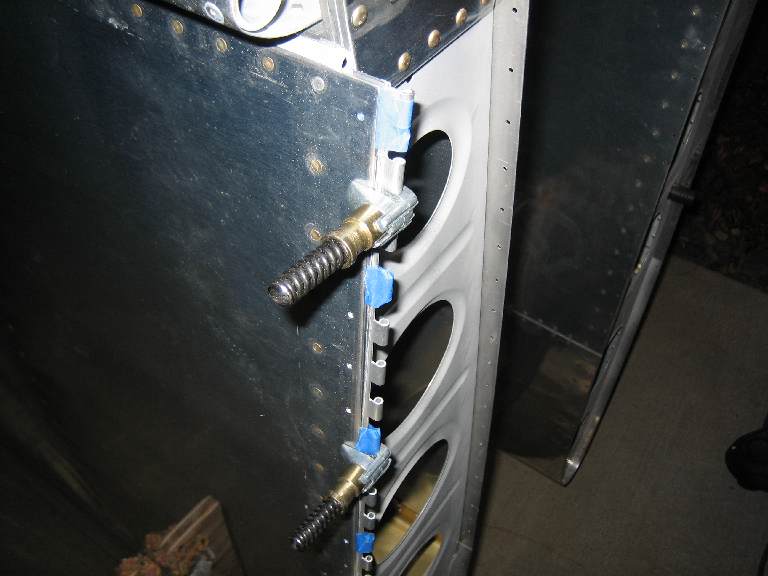
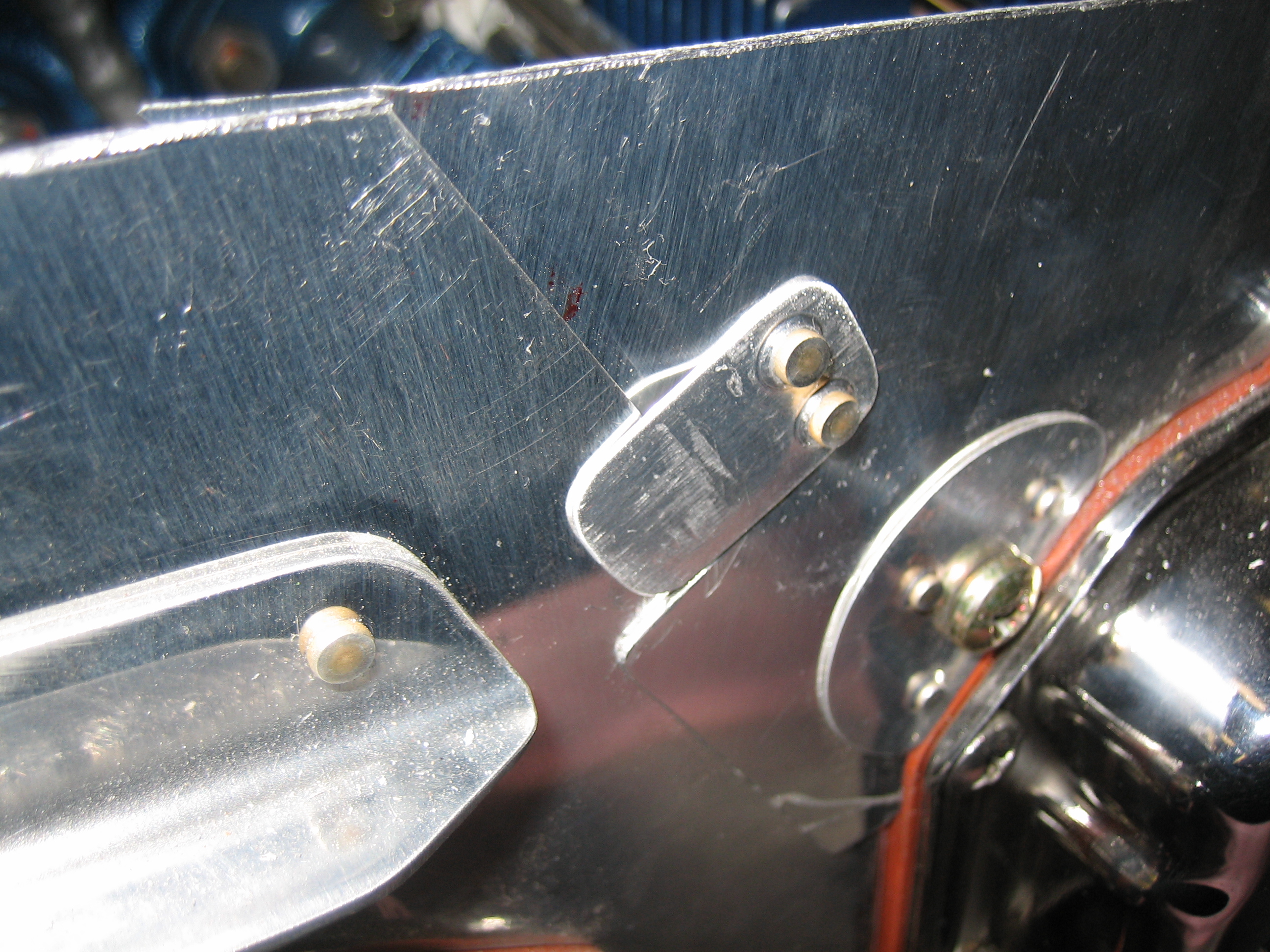
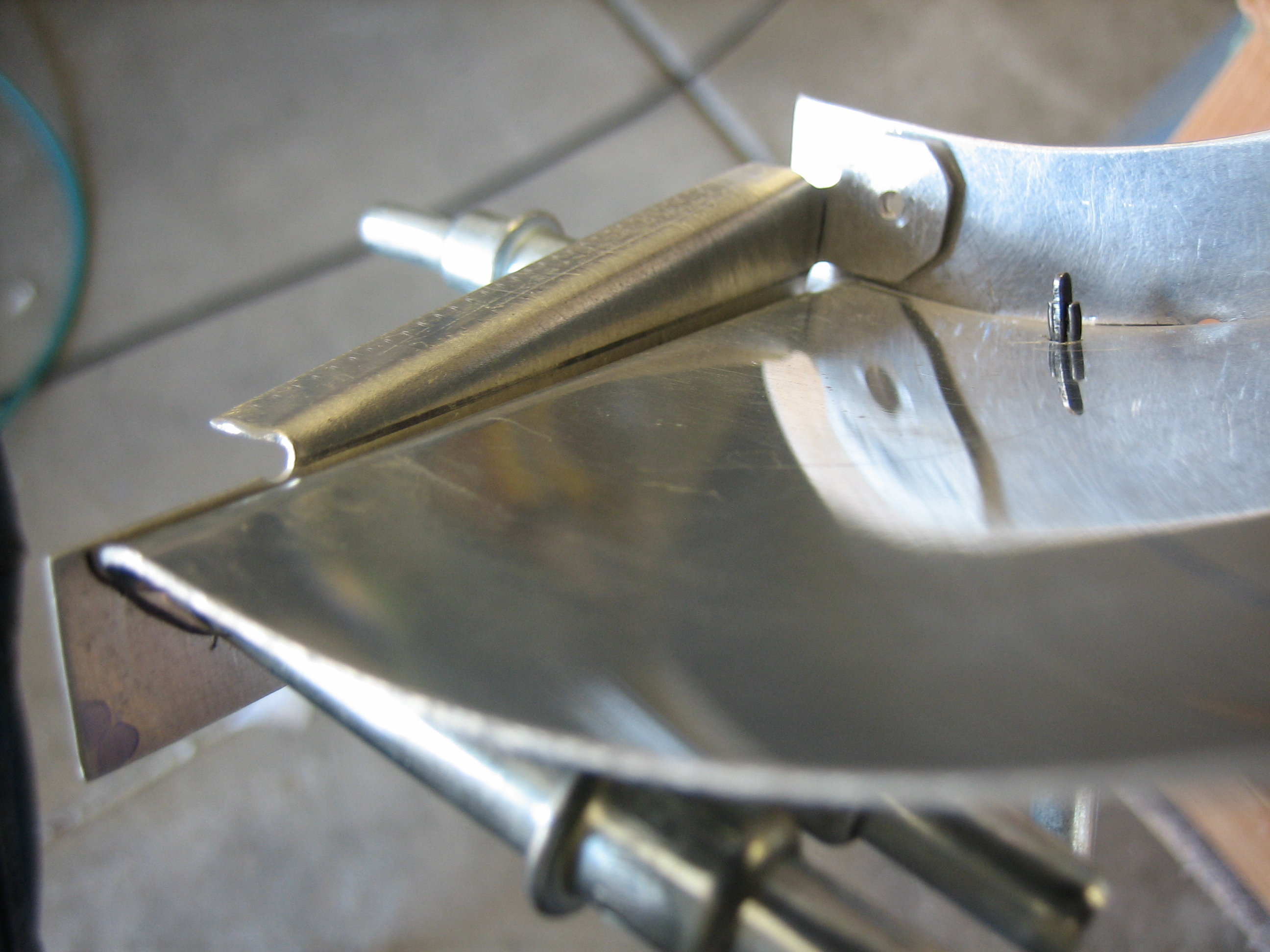
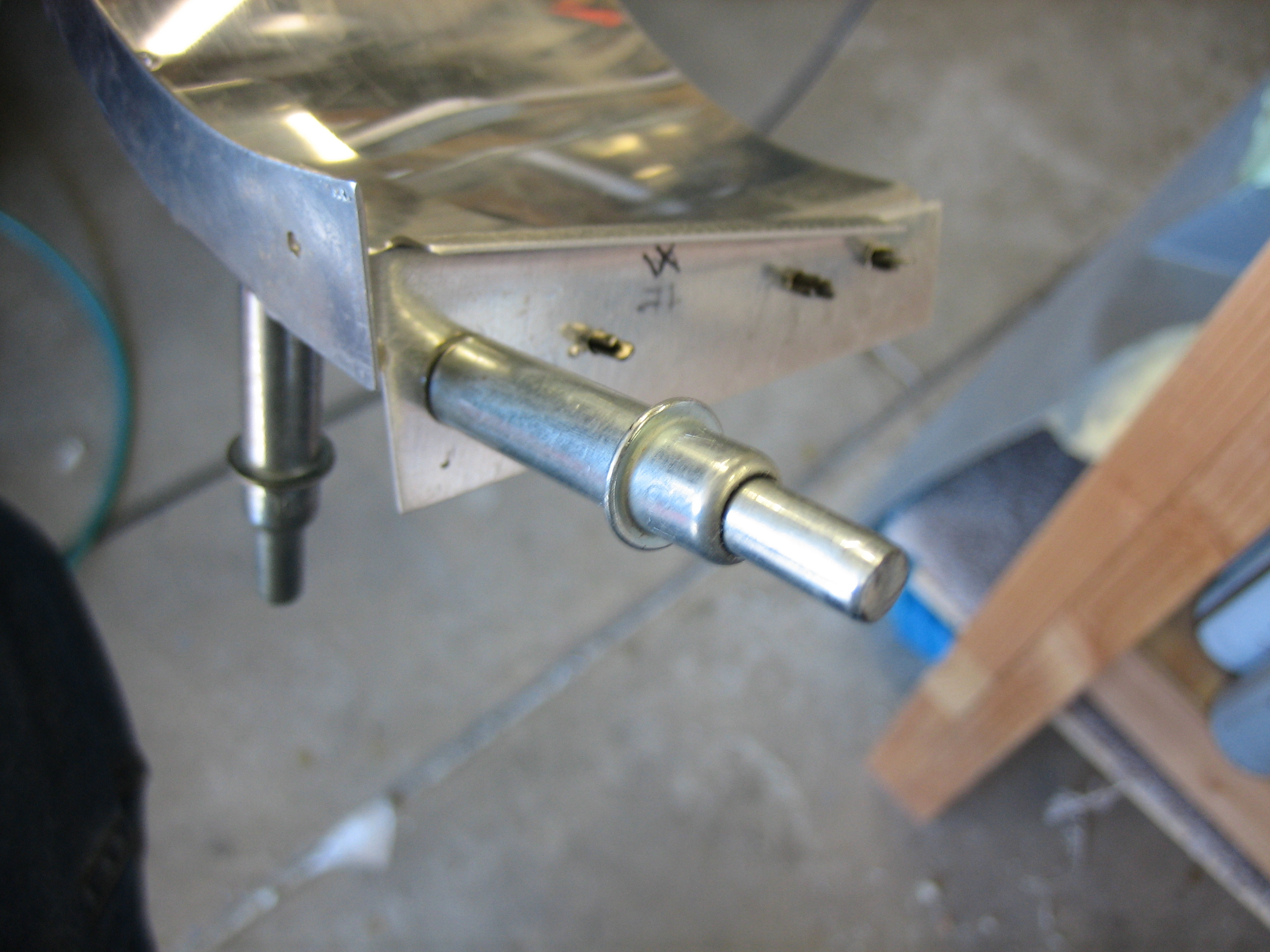
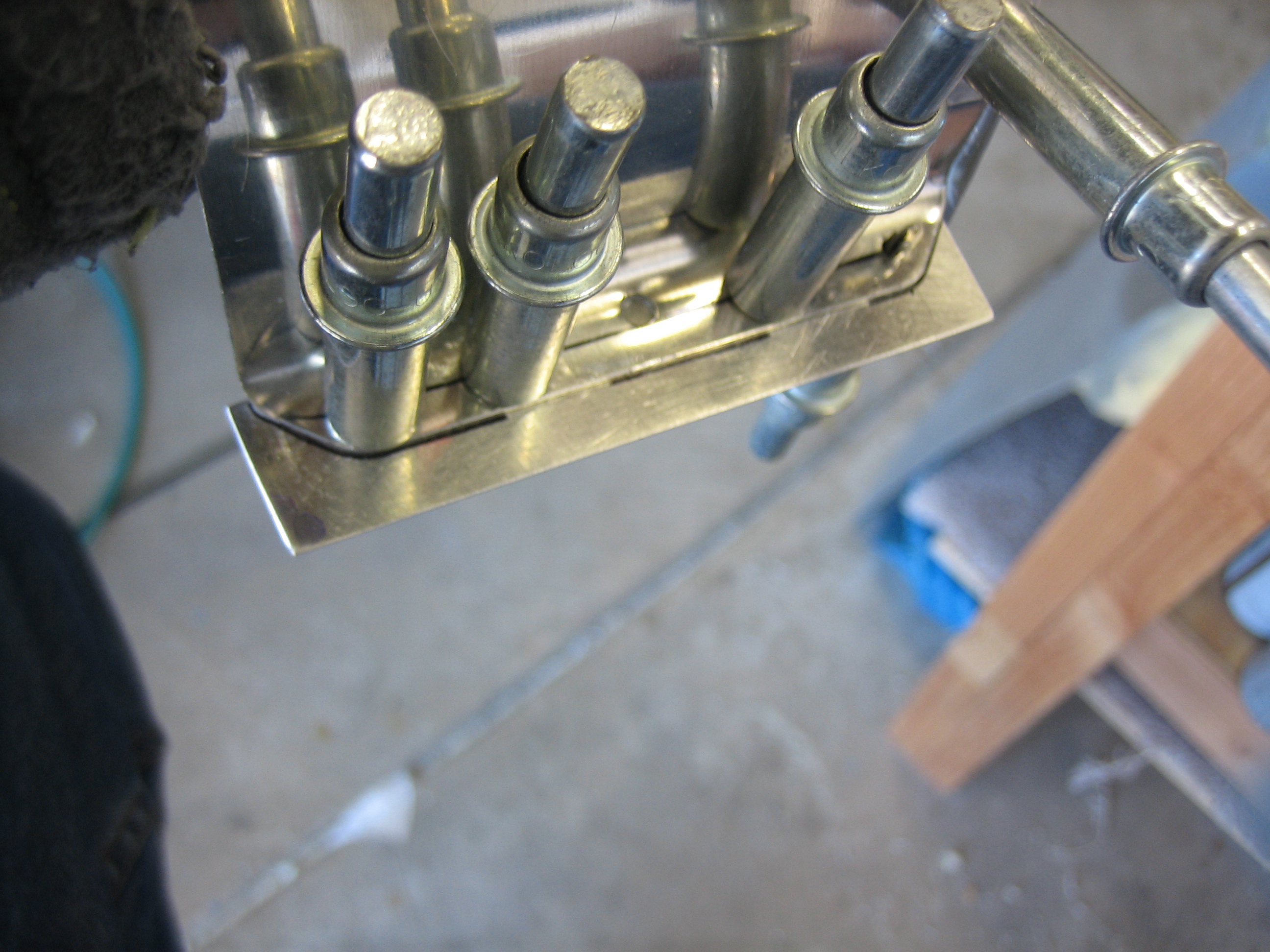
I also made a little more progress on the hinges that will be used to attach the wing tips. I taped a couple of the spacers to the hinge and then clamped it to the wing skin.
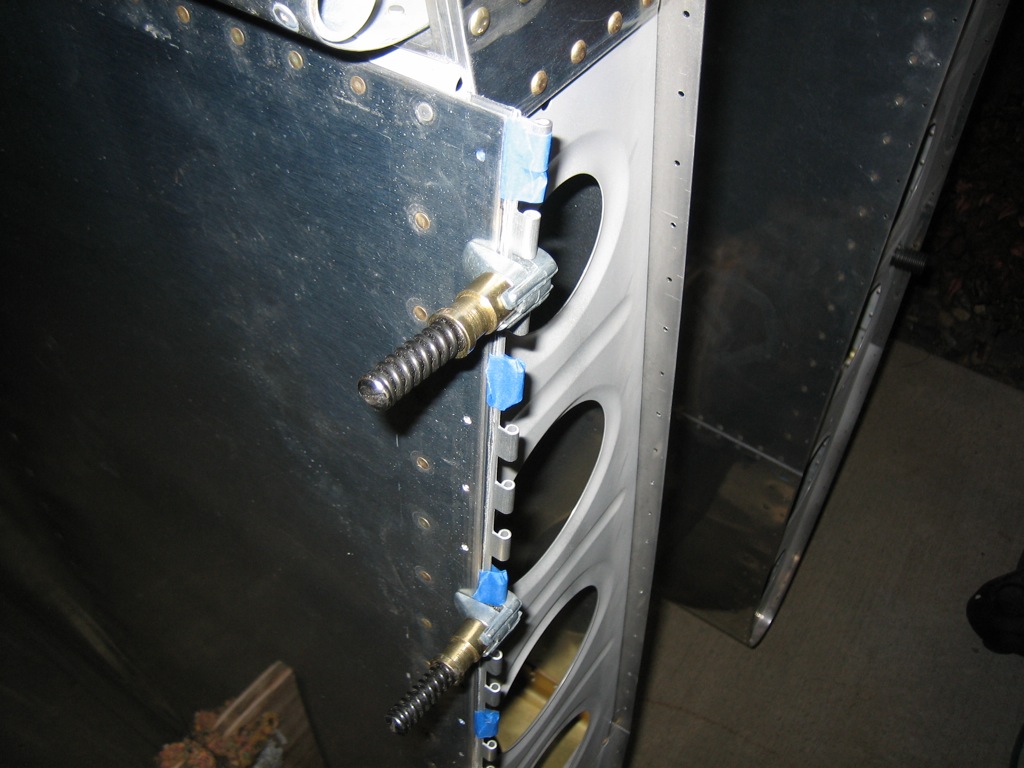
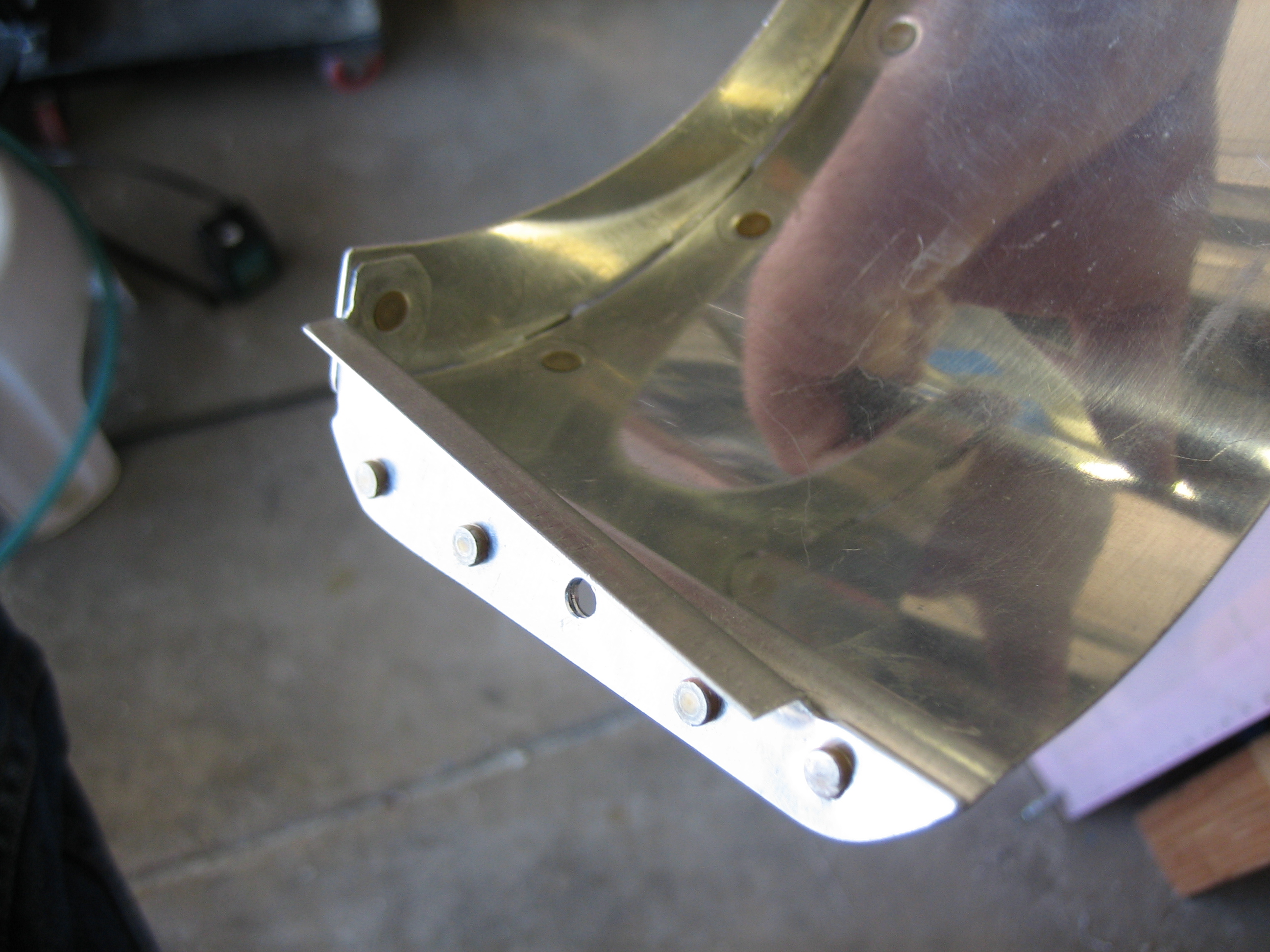
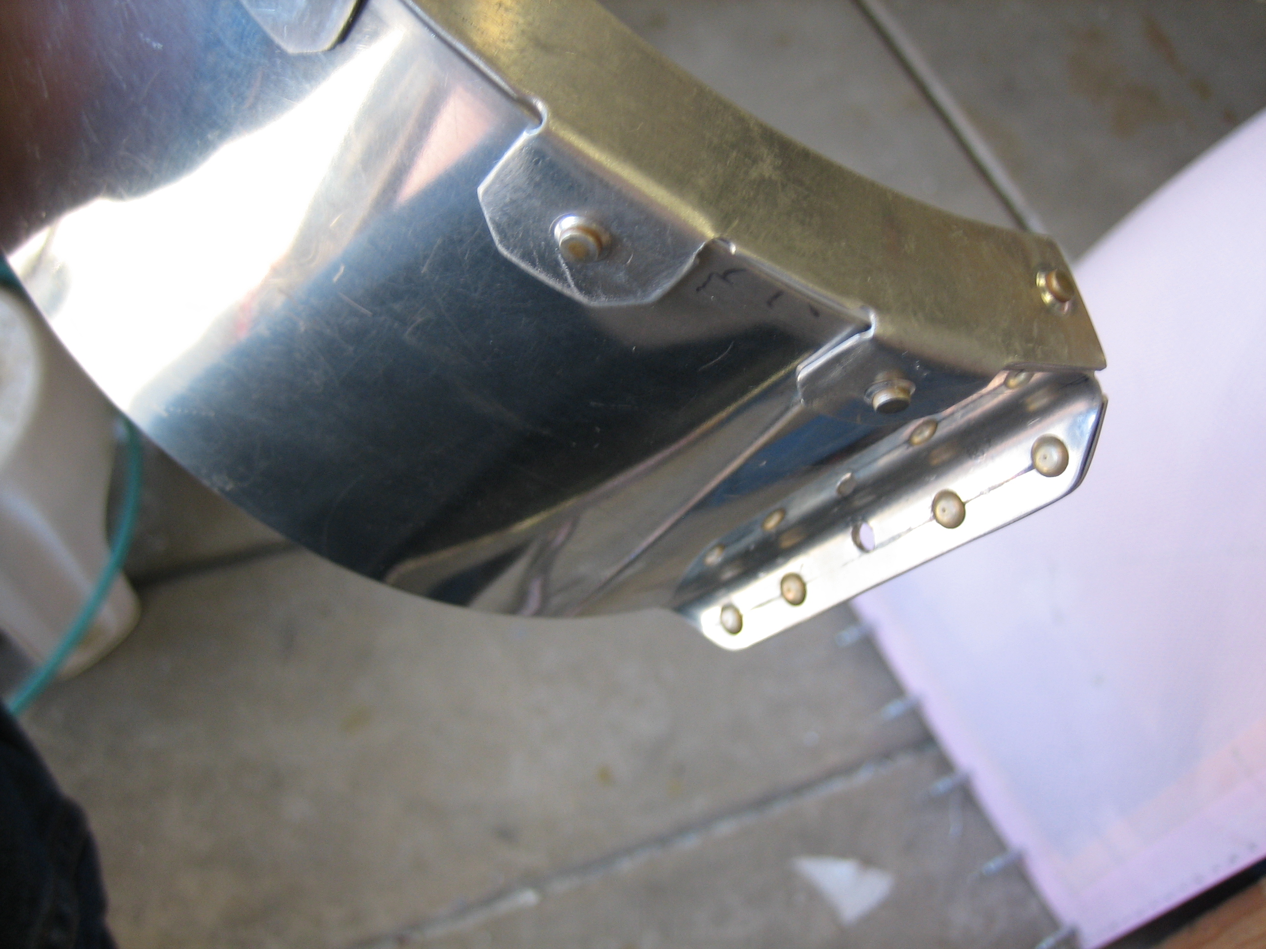
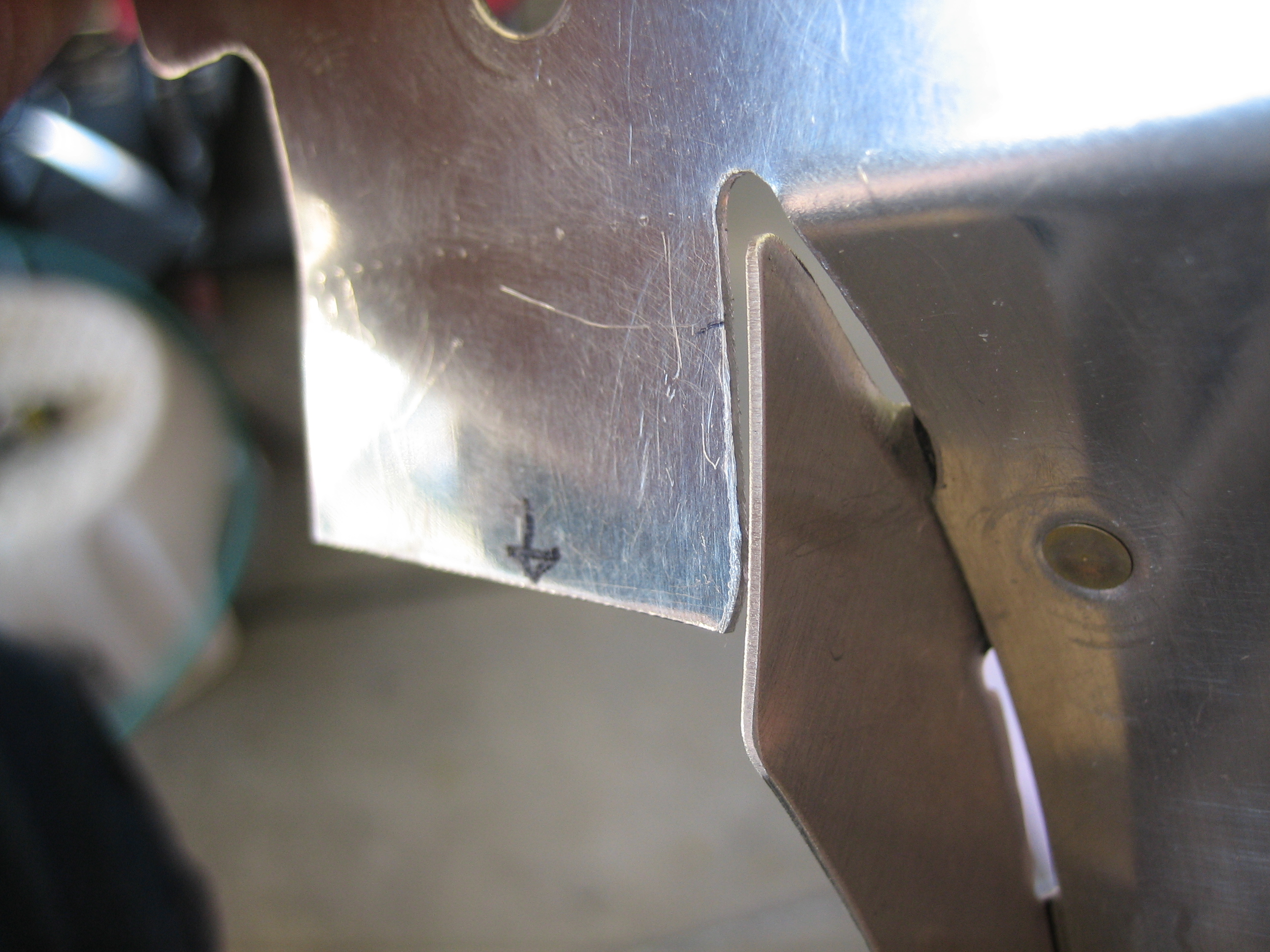
After drilling, deburring, dimpling, and countersinking, I riveted it on. Notice that the wing side of the hinge starts with an eyelet at the trailing edge. This is so that the hinge pin can be pre-loaded on the wing so that it’s ready to go when the wingtip is set in place.

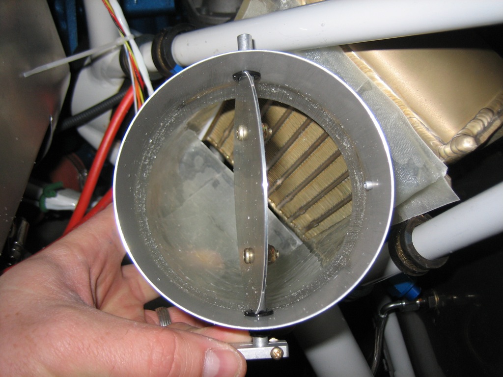
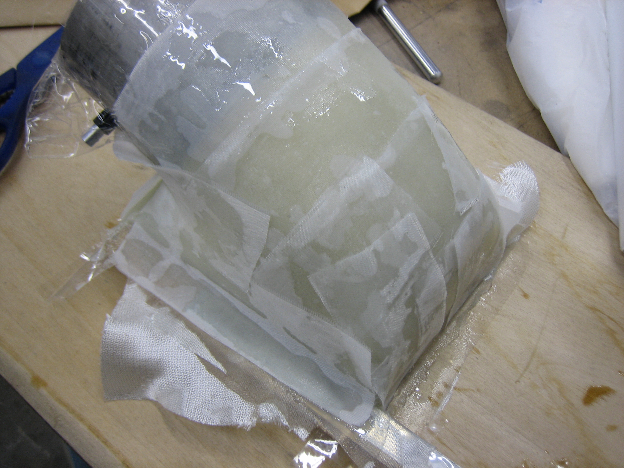
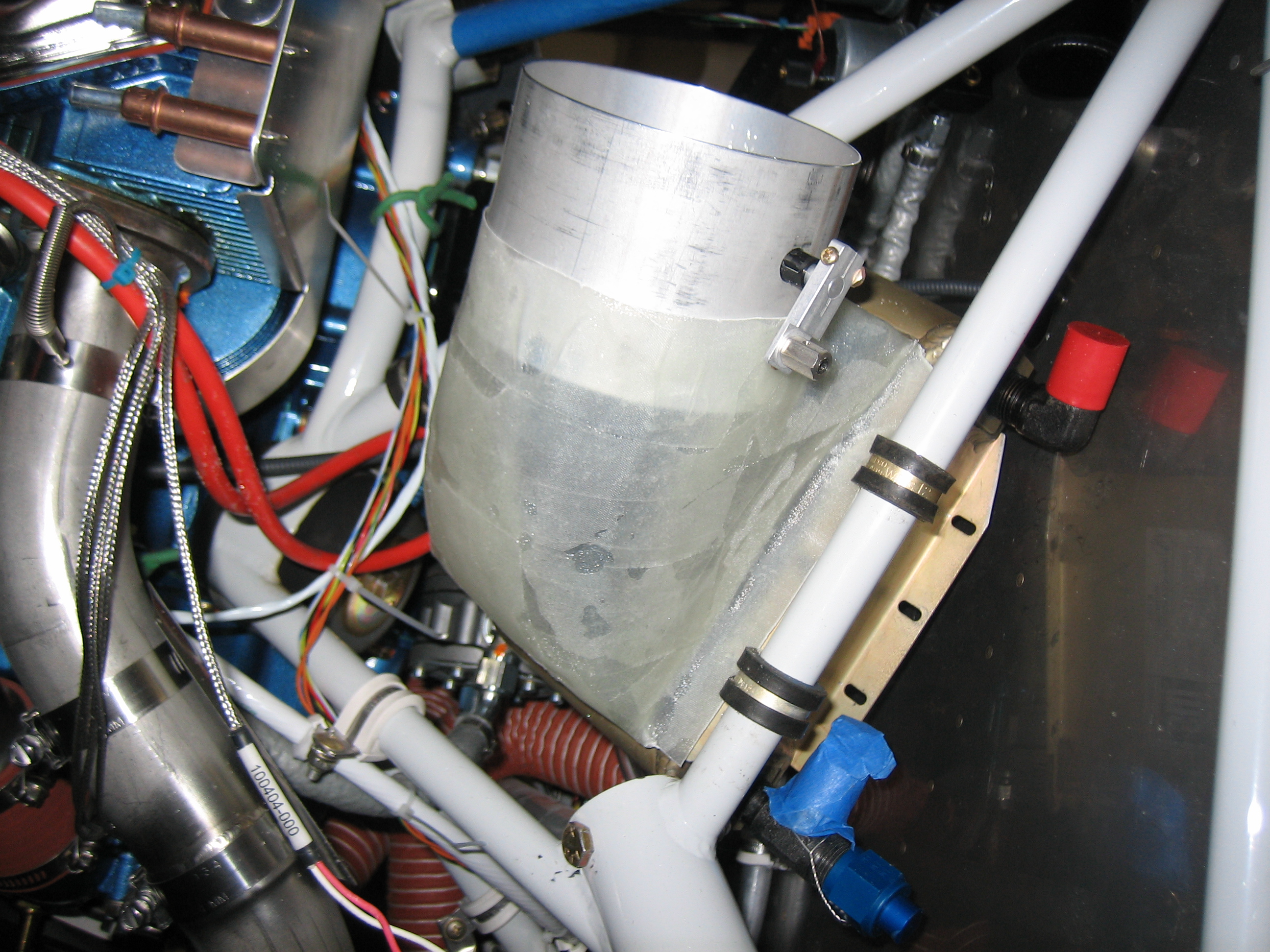
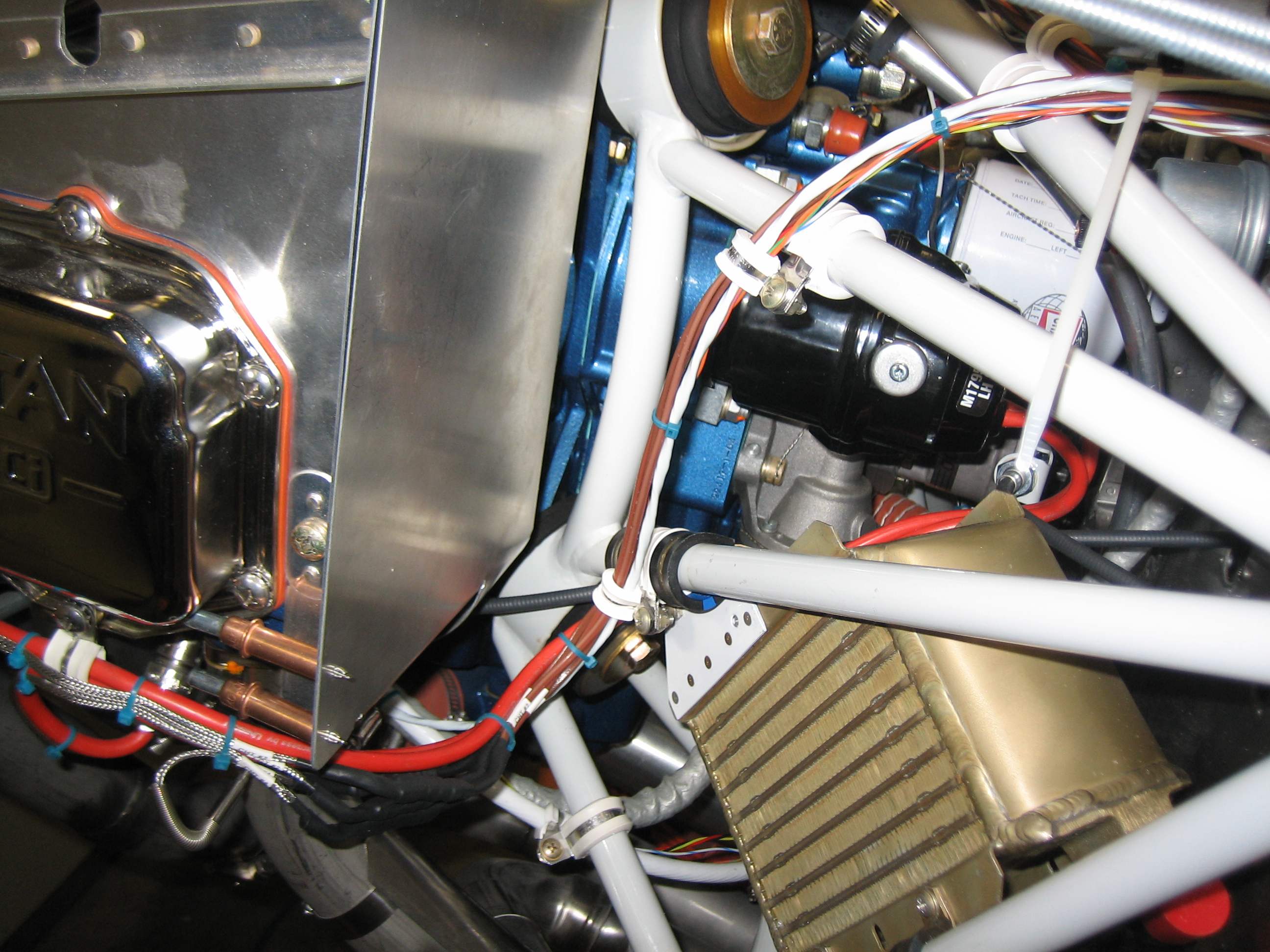
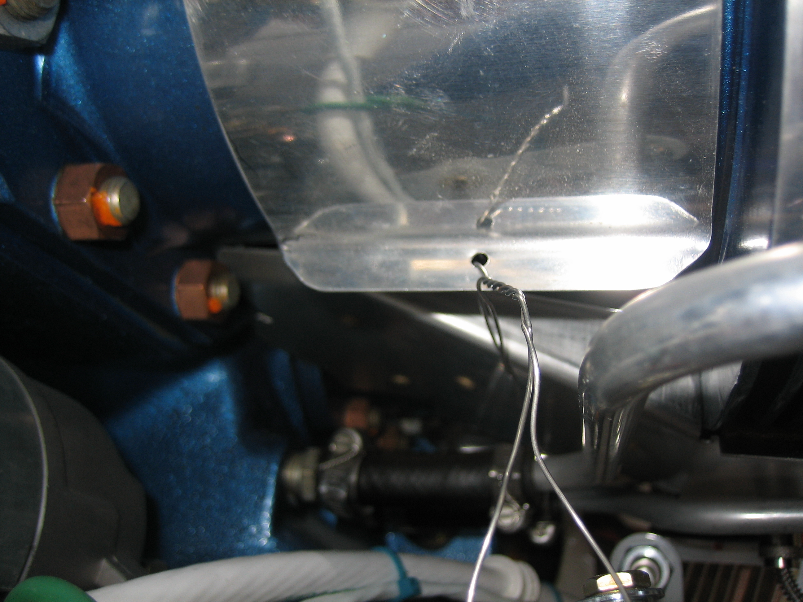
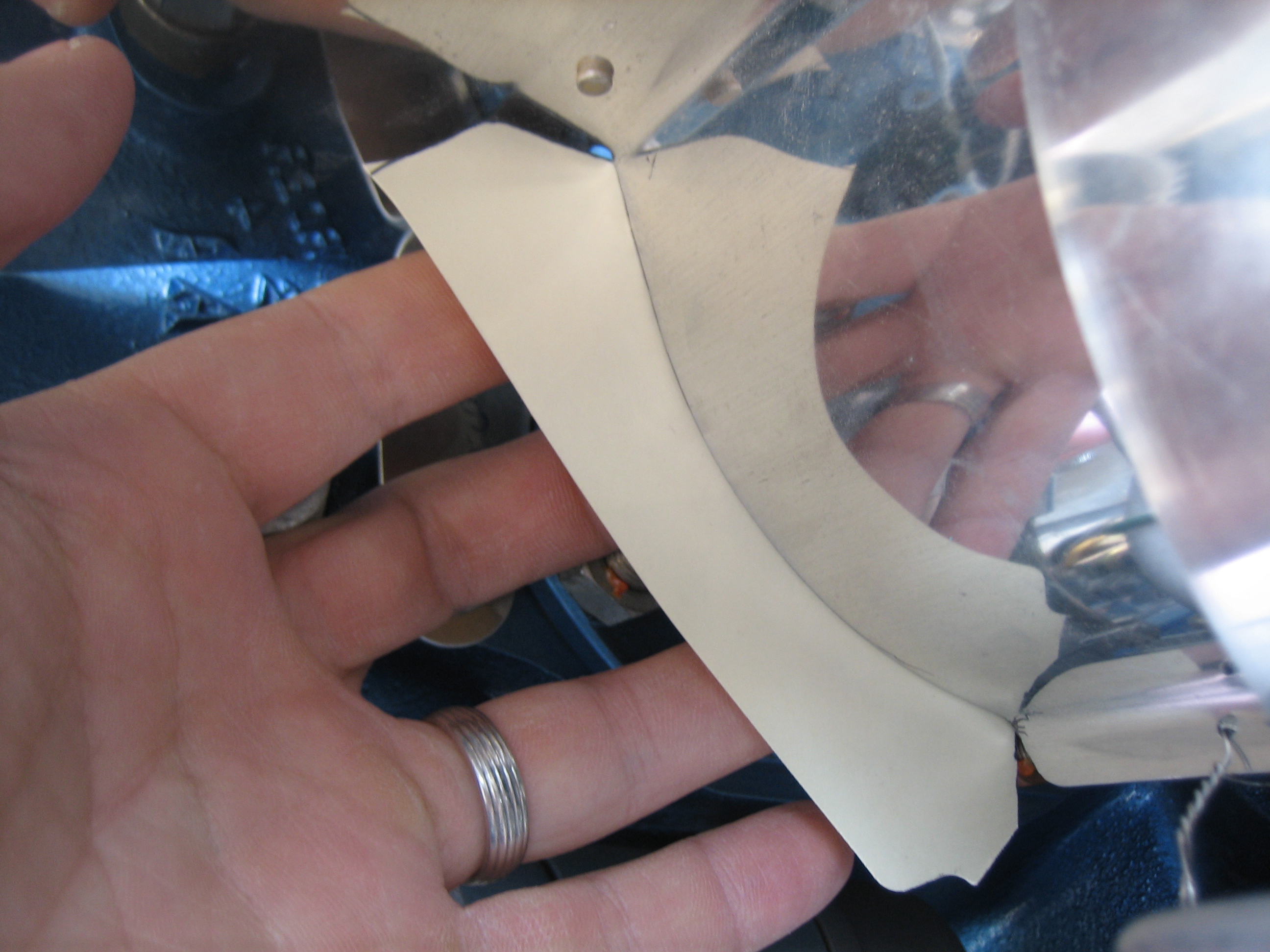
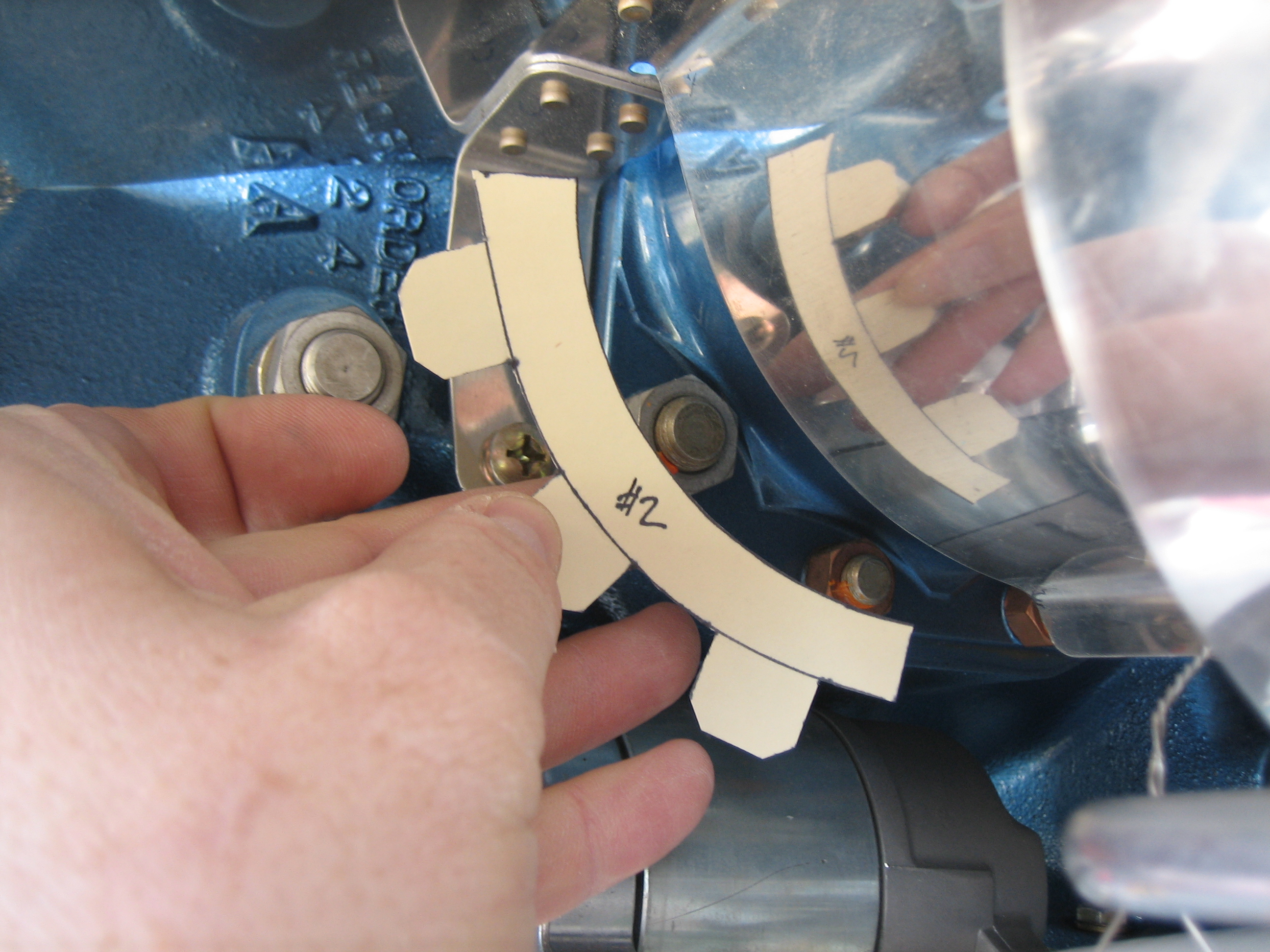
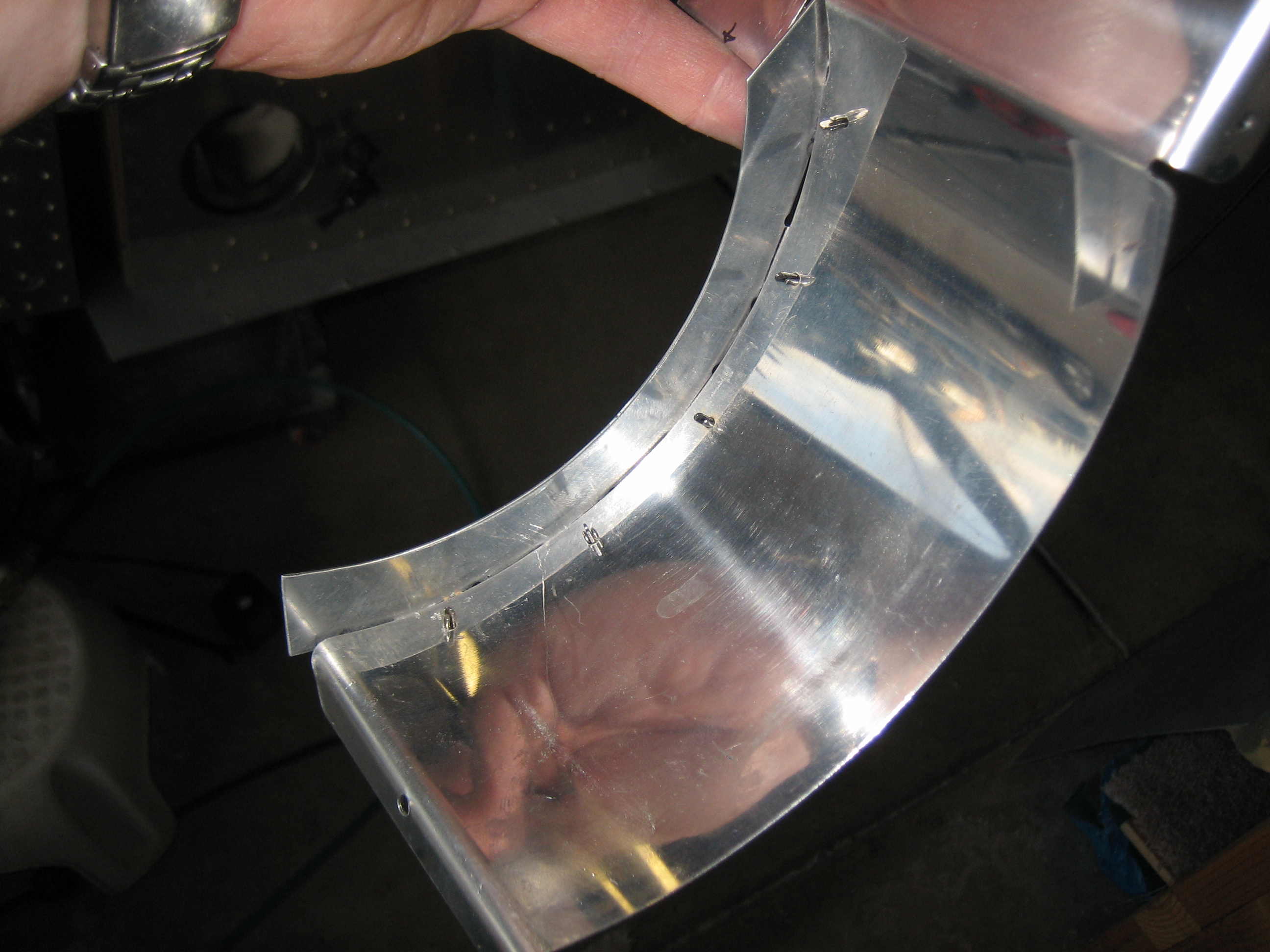
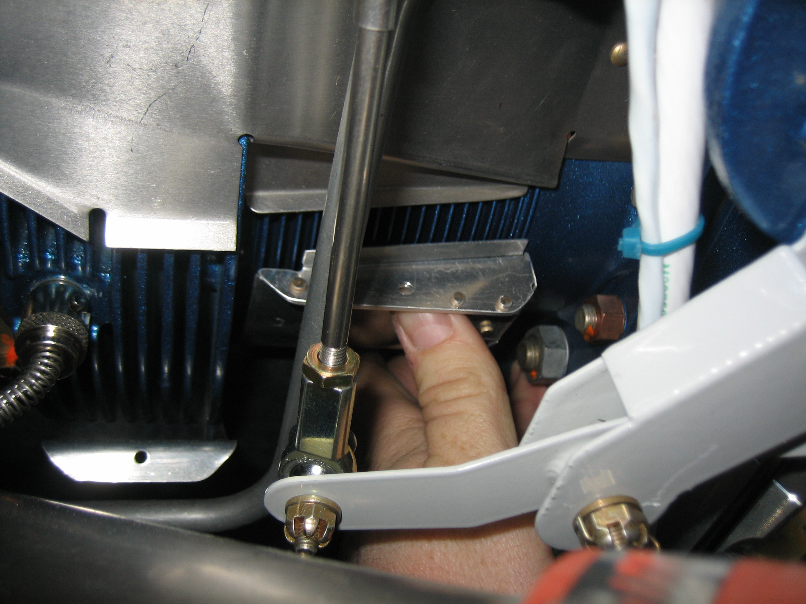
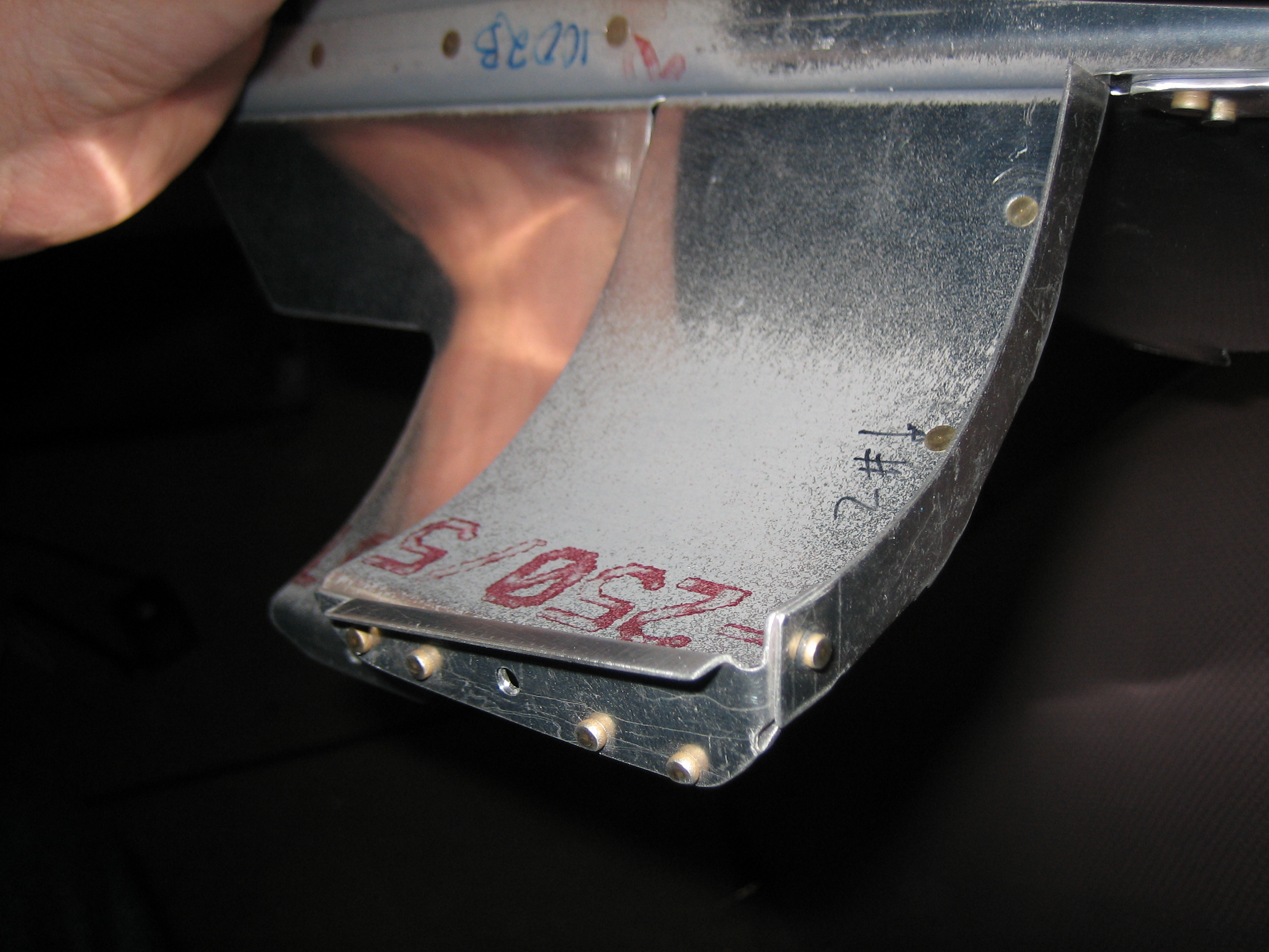
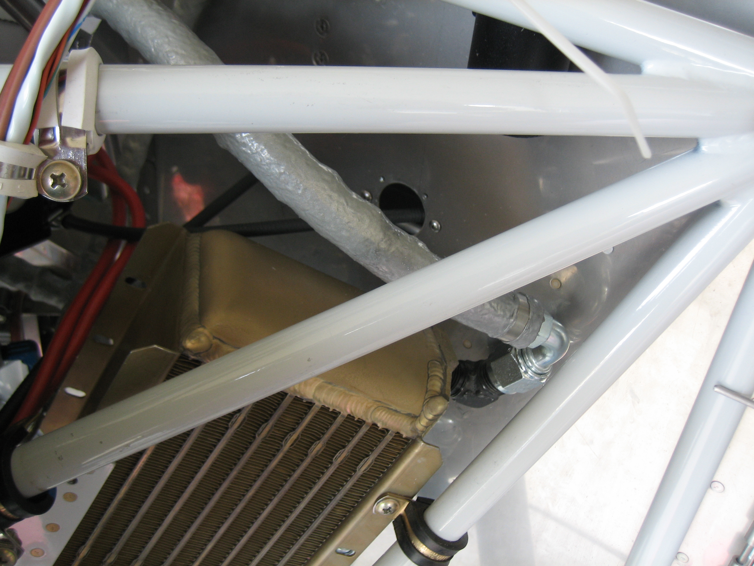
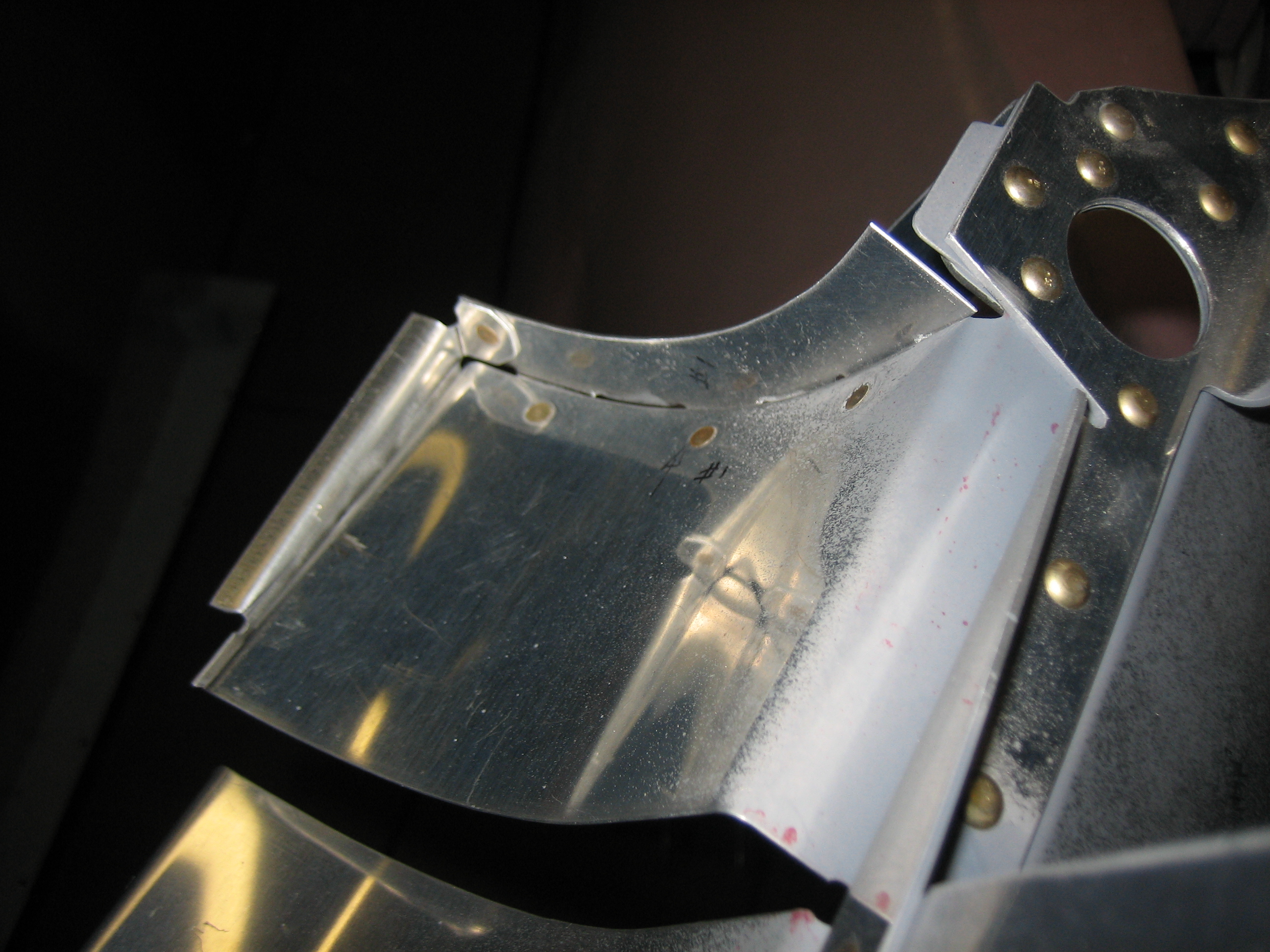
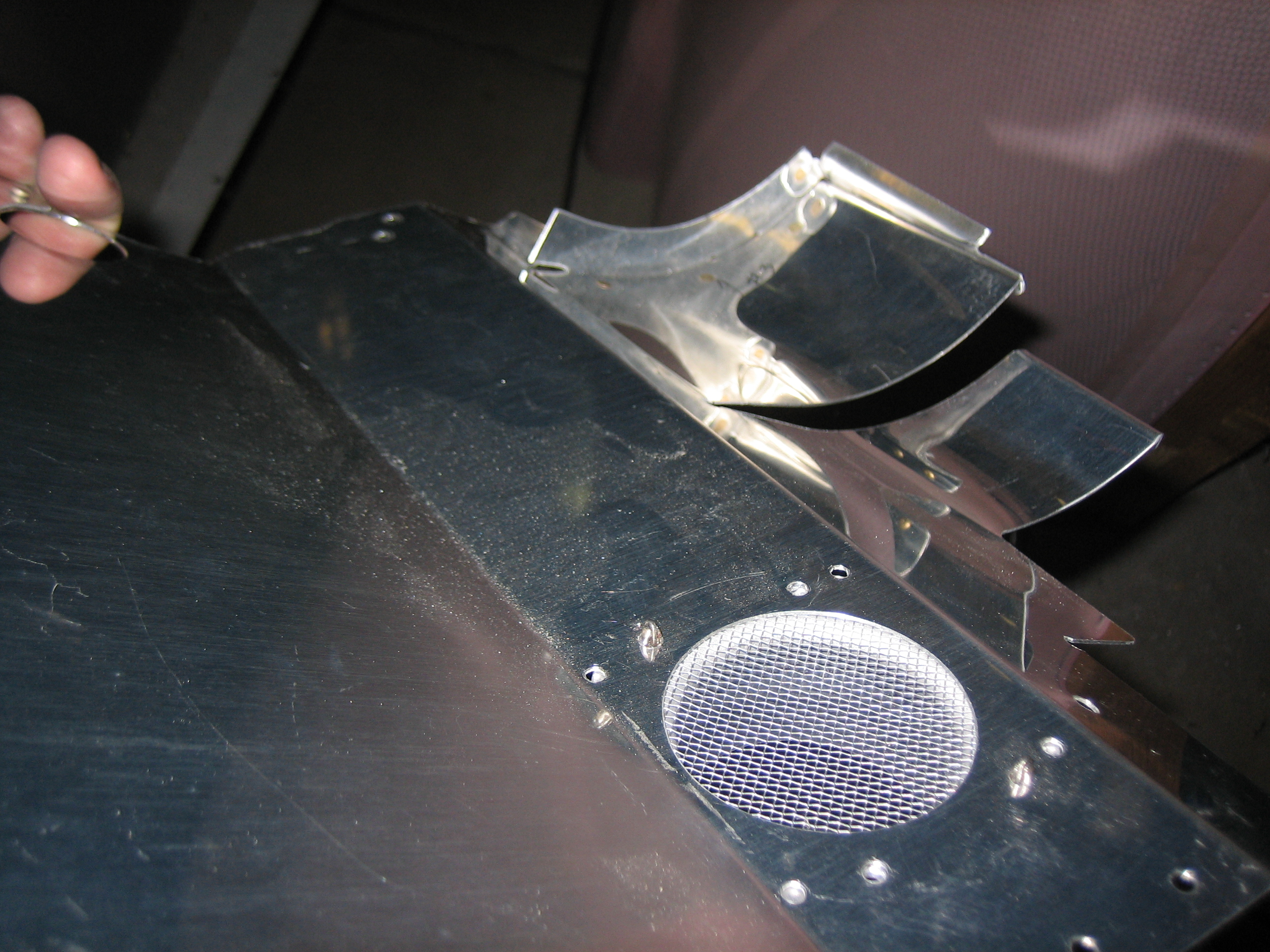
I also pulled the oil cooler plenum out of the mold (well, mostly pulled the mold out of the oil cooler plenum) and then test fit it. It looks like it fits pretty well, but I’ll have to do a little adjustment. As I suspected, it’s also way too flimsy right now due to the lightweight cloth I had on hand. I have some 9oz cloth on order. A few more plys of that should stiffen this up nicely.

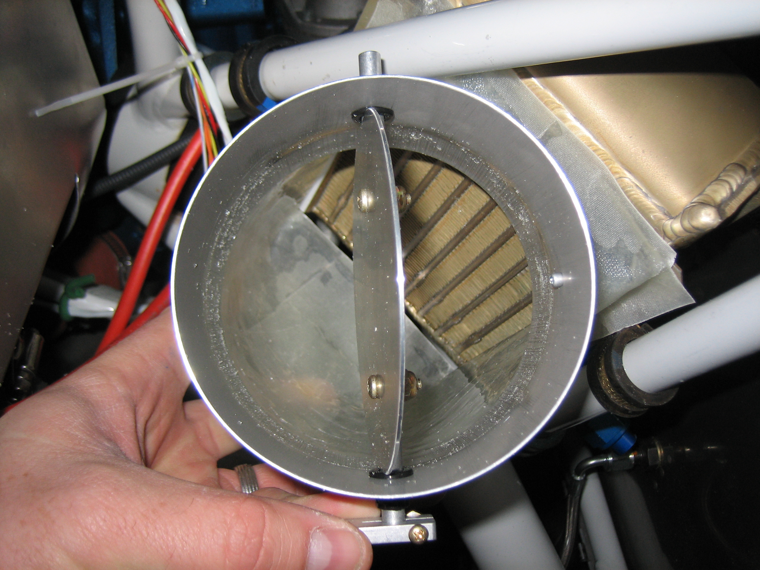
Here’s a shot down the inside. With the butterfly valve open, the air will have a nice clean shot at the oil cooler fins.