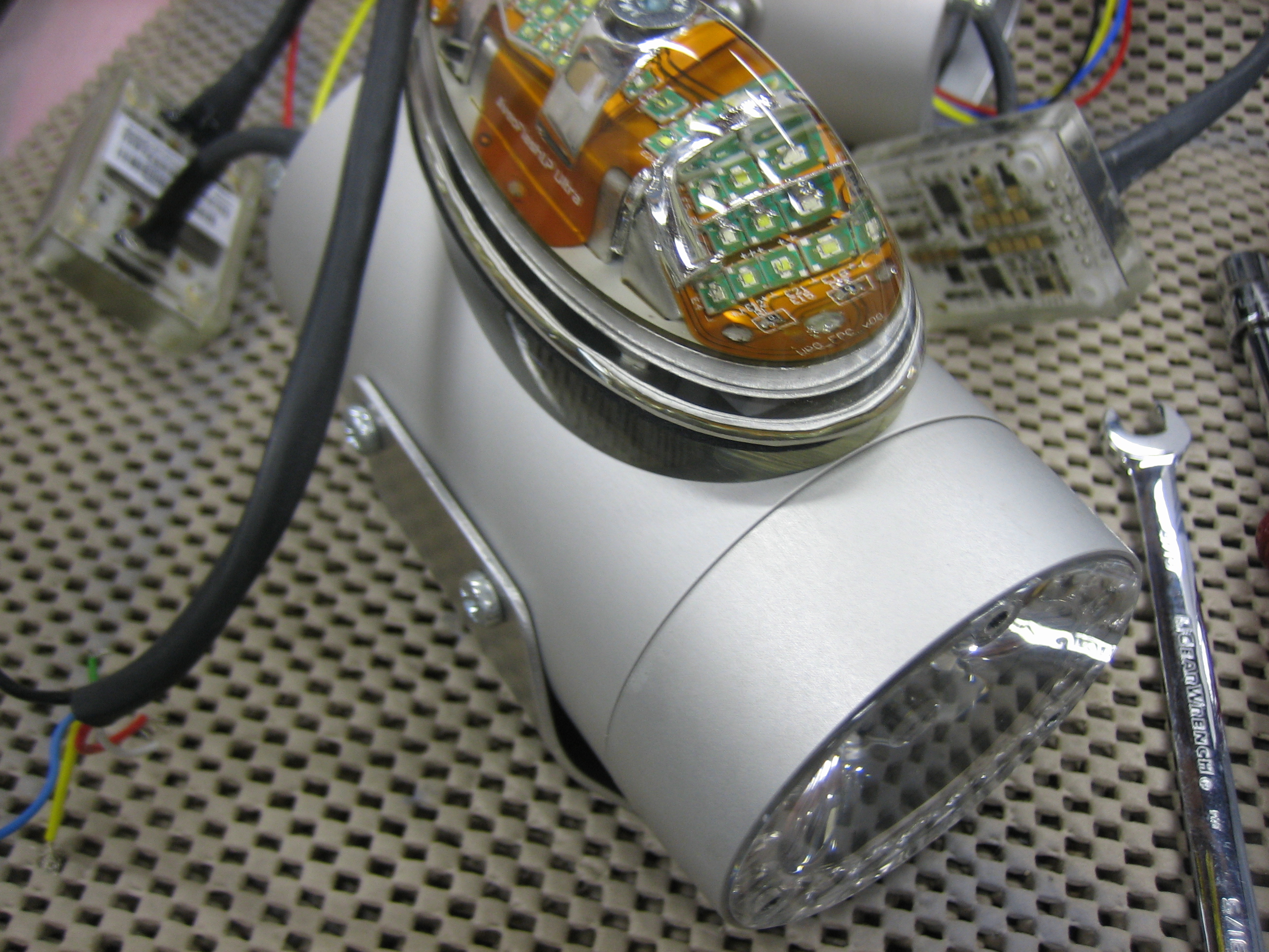
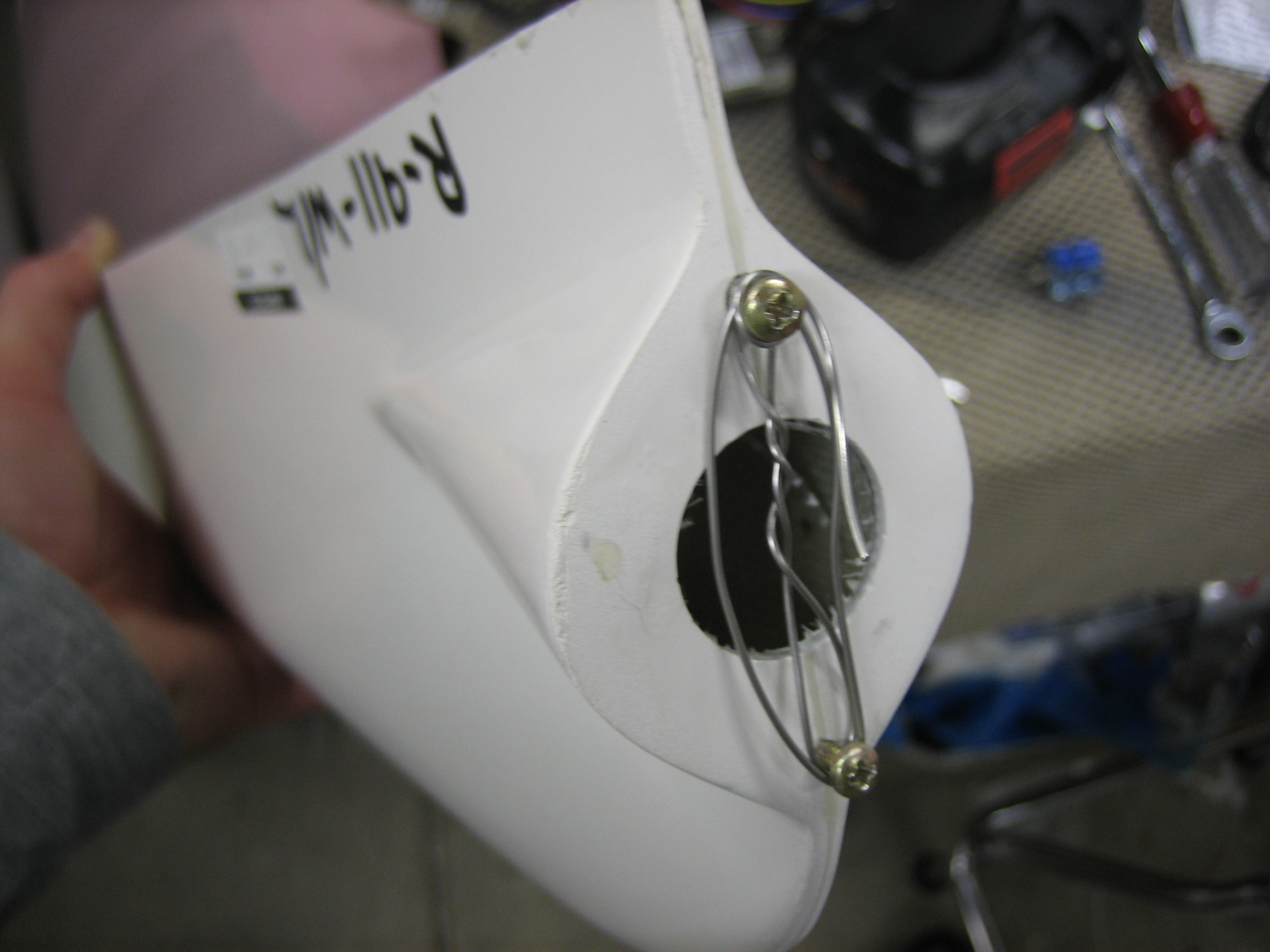
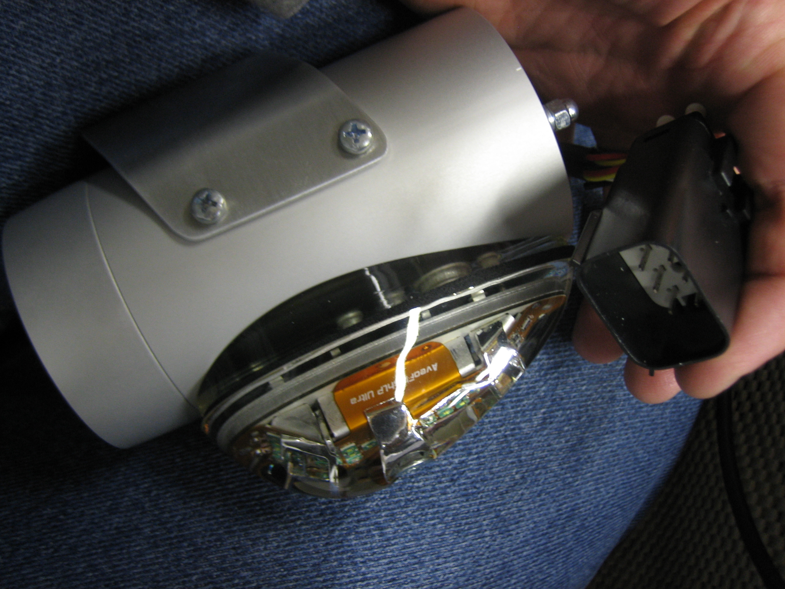
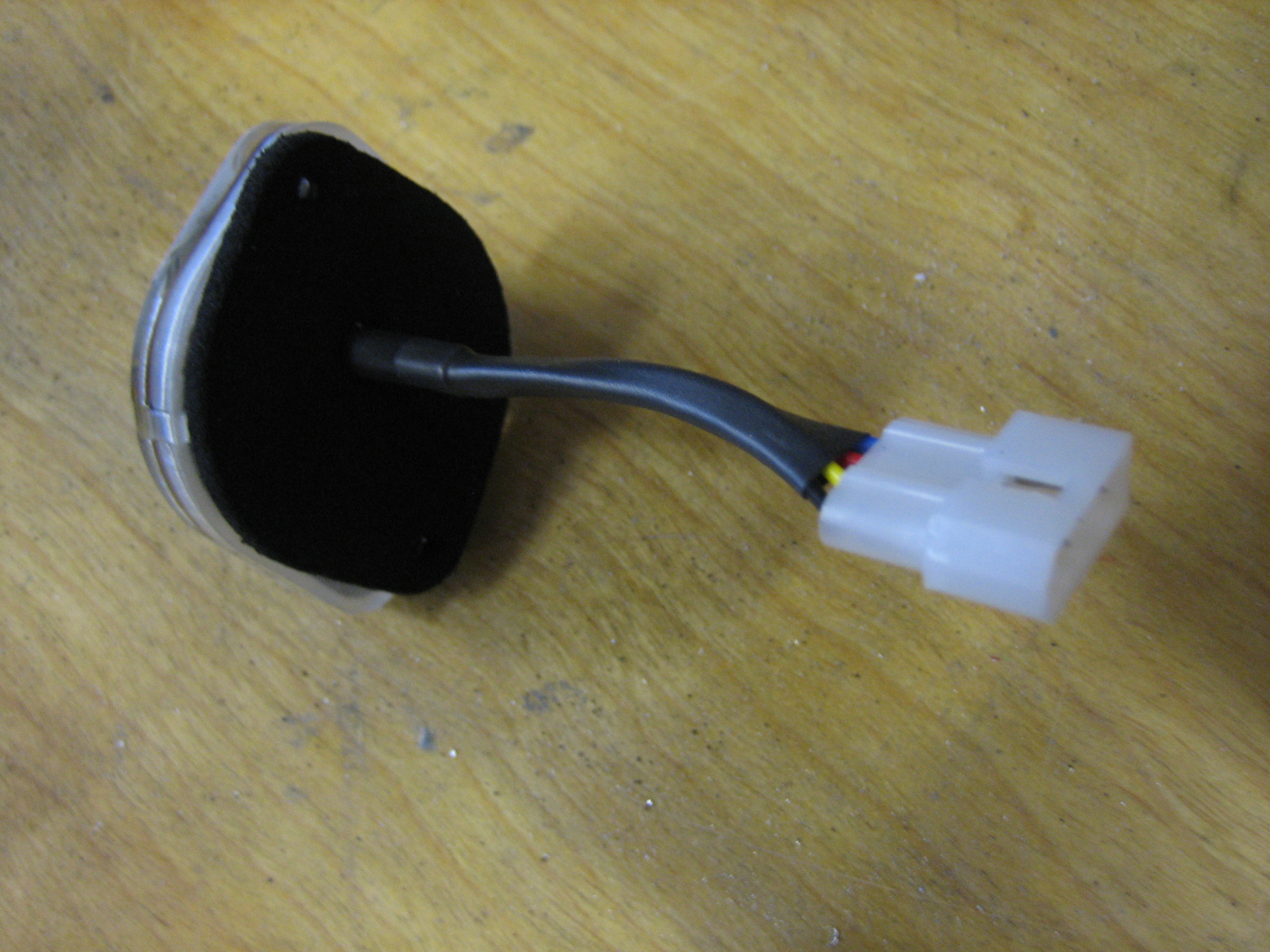
I started working on the wingtip lights tonight. I’m going to fabricate a reflective backing for both sides of the recess, so I was fairly generous with the cutout so that I can easily position the light. I’ll trim the backing to tightly follow the lights. I don’t want to determine the final position until the nav/strobe light is attached and the lens cover is trimmed so that I can make sure there is no interference. This is approximately where the light will end up though. The is substantially farther forward than the stock lights which should provide better lighting directly in front of the plane. The stock light position puts the bulbs a good 4″ farther aft which causes the side of the recess to shade the area directly in front of the plane.
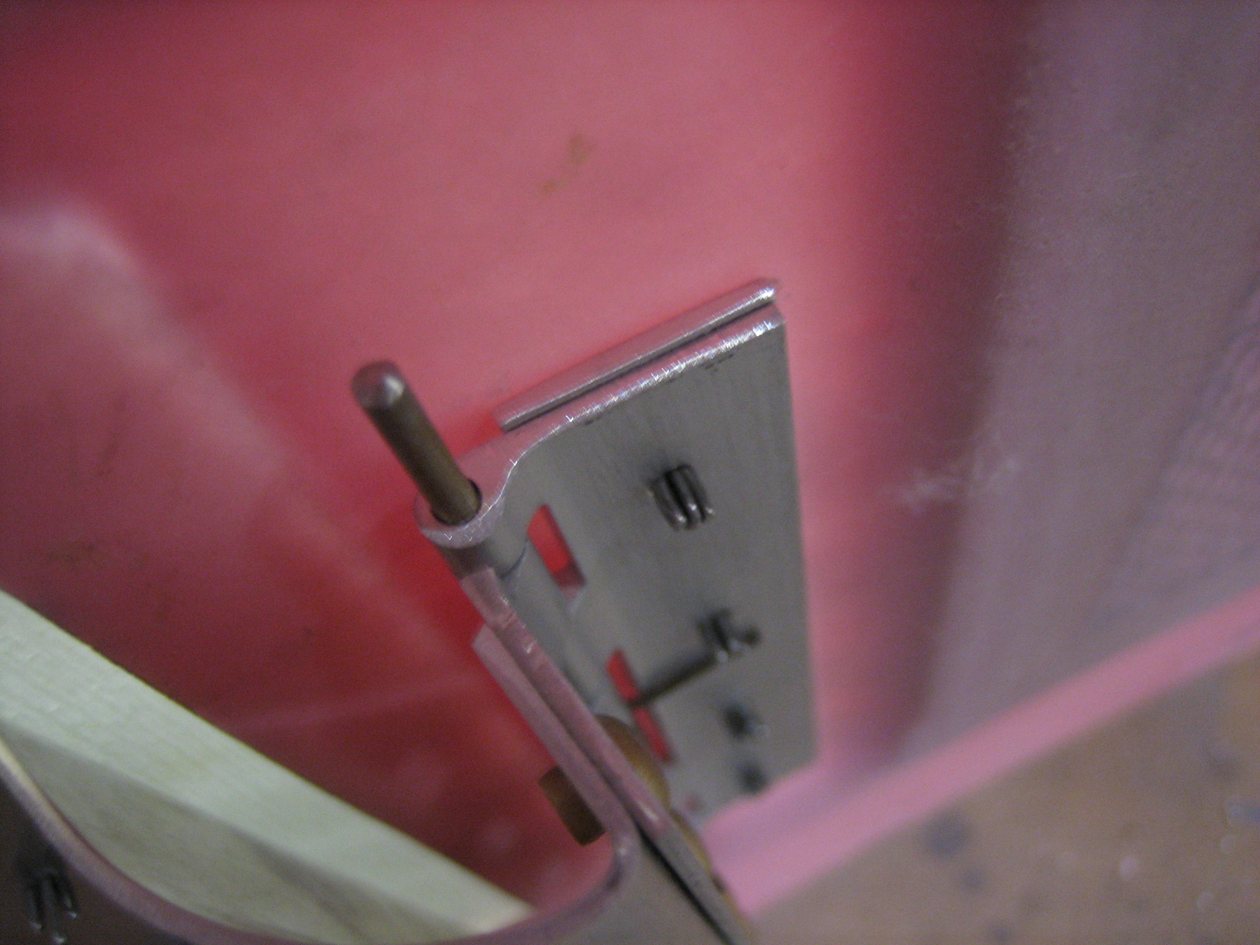
Once I have the lens trimmed, it looks like I can probably push the light even farther forward. I’m going to try and get it within about 1/4″ of the lens. Since the light runs really cool, I don’t have to worry about overheating the lens on the ground. In flight, there’s obviously enough airflow that I wouldn’t have to worry about heat anyway.
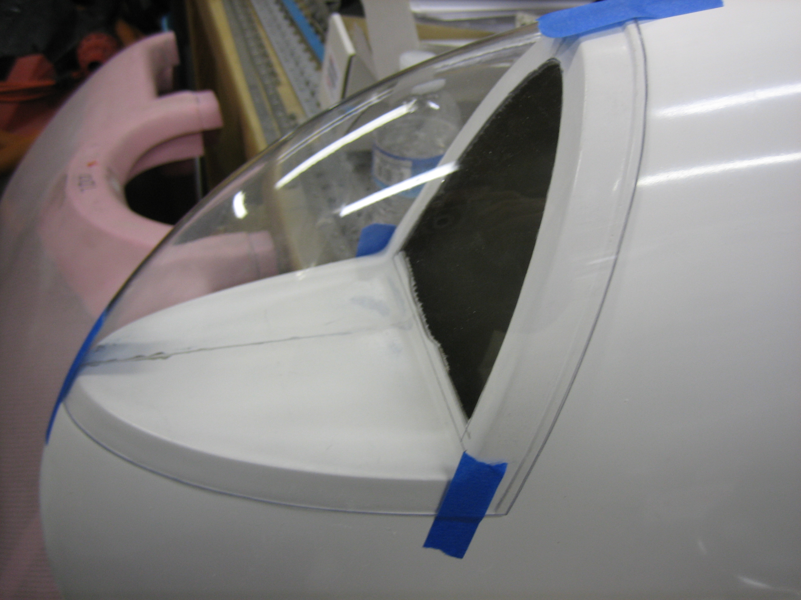
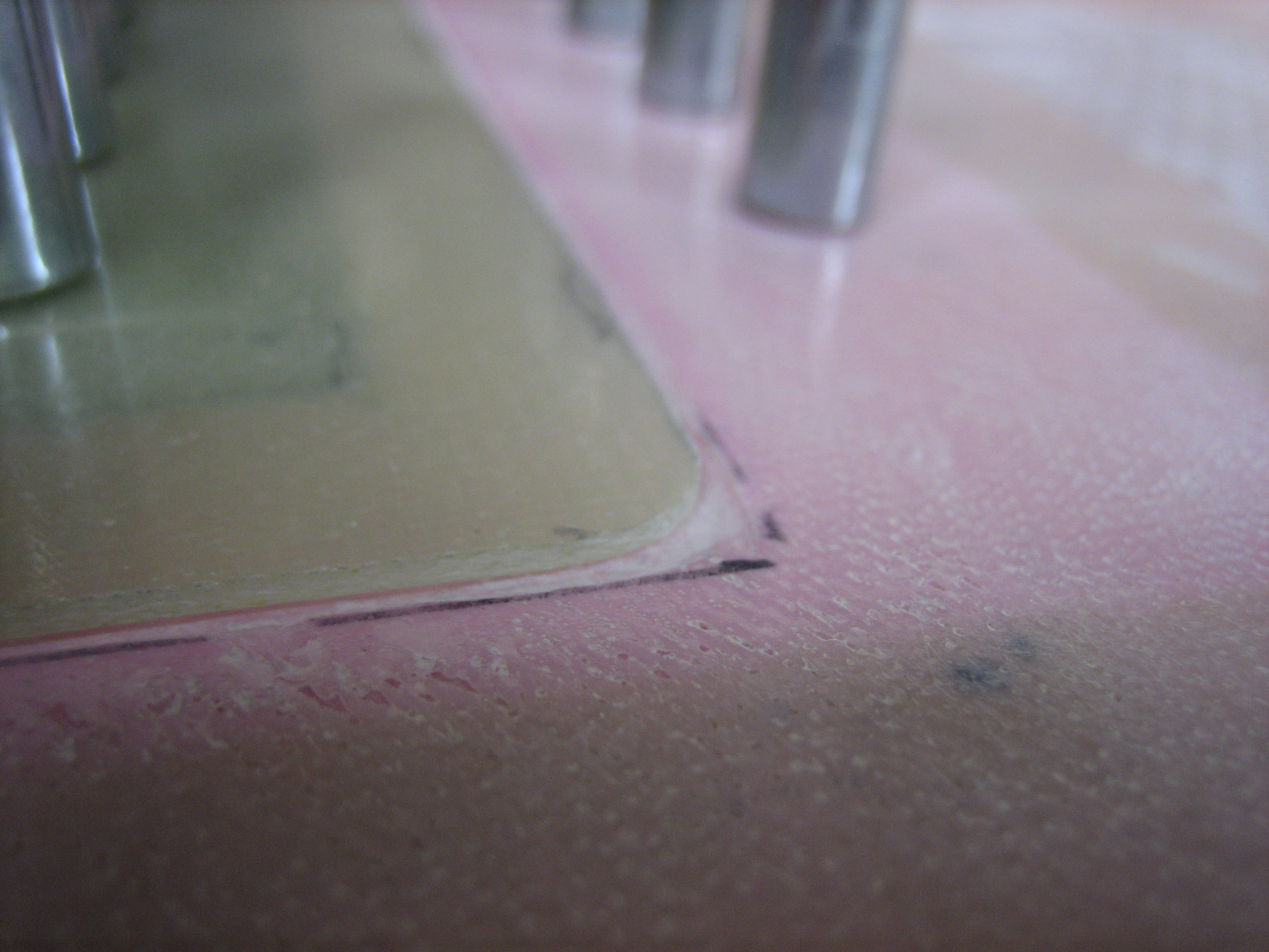
I adjusted the lens until it looked like it would precisely follow the curvature of the outer edge of the wingtip and then taped it down. I used some masking tape to mark the cut line. The lens will pull back farther after it’s cut, so this will just be a preliminary cut line.
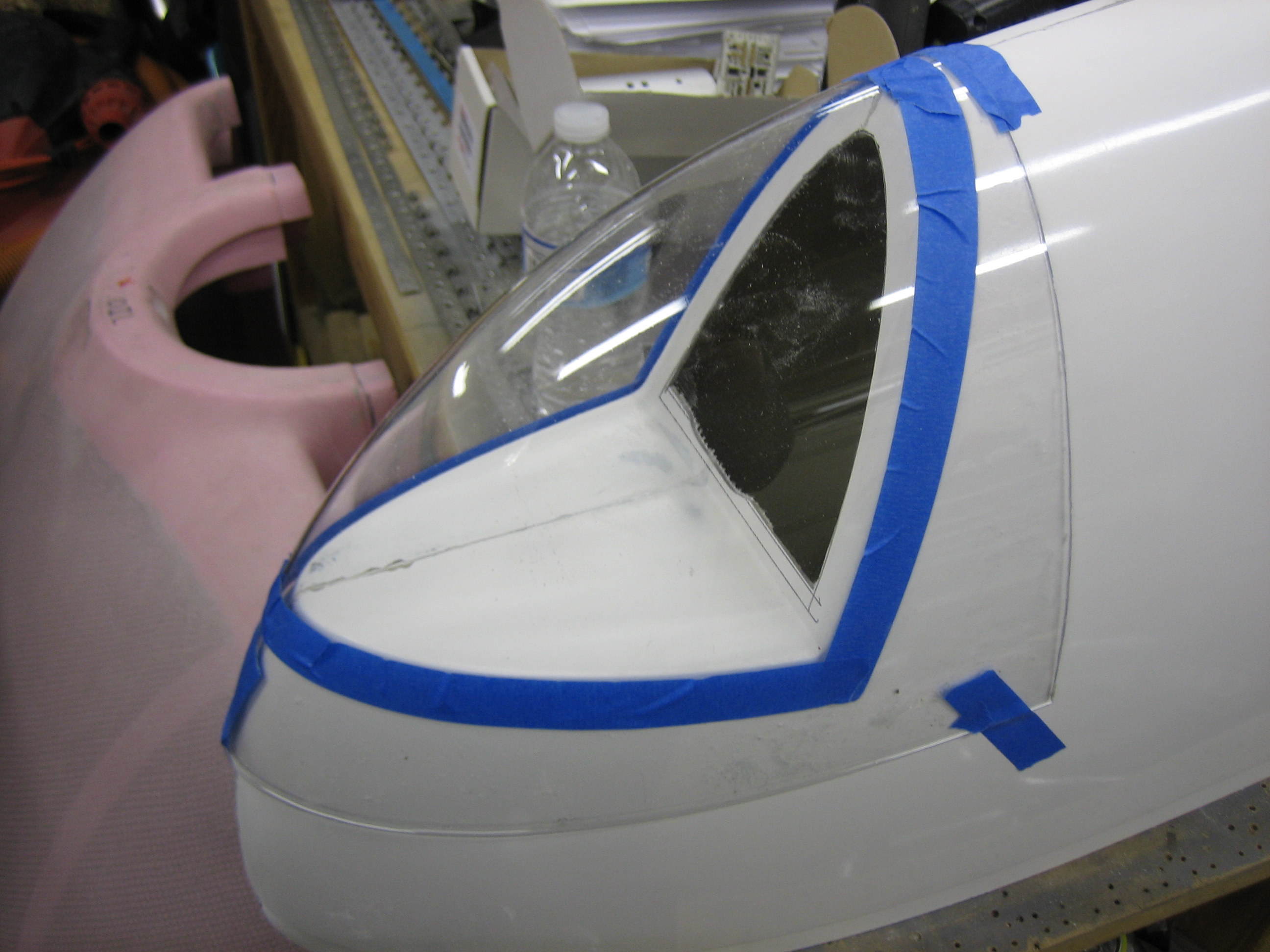
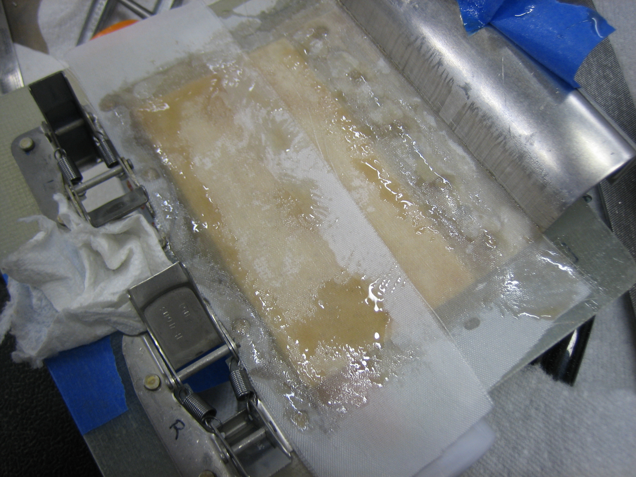
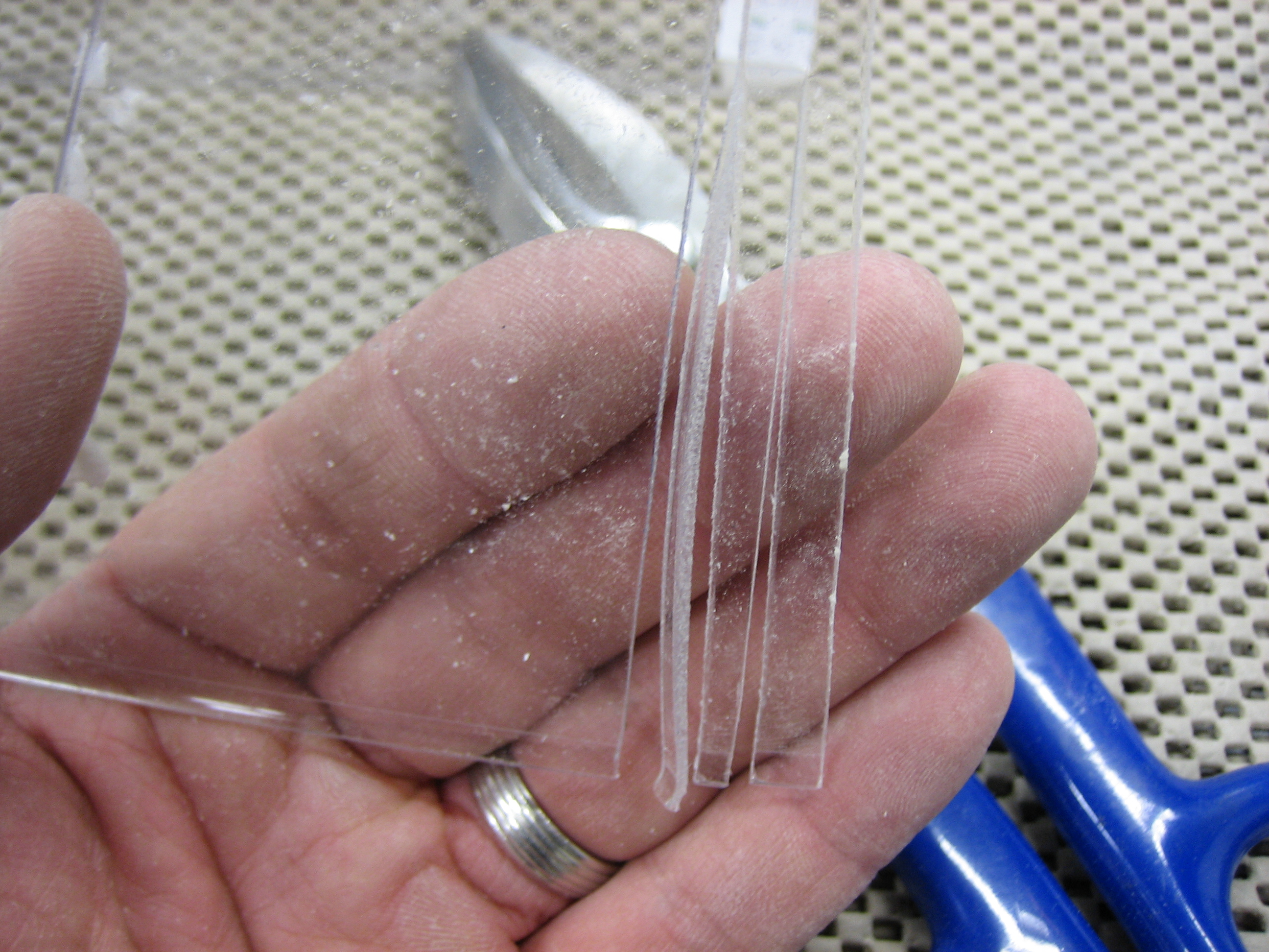
I played with some tin snips along the edge, and they made perfect cuts without any hint of cracking the plastic, so I used them to cut out the lens. This was far better than using the cutoff wheel since I could basically trim right to the line and then touch up the edge with some sandpaper to remove any microscopic burrs that could create stress risers and lead to cracks down the road.
With one edge of the lens aligned with the flange around the recess, it looks like I’ll need to trim about 1/8″ off of the other edge to allow it to drop behind the lip.