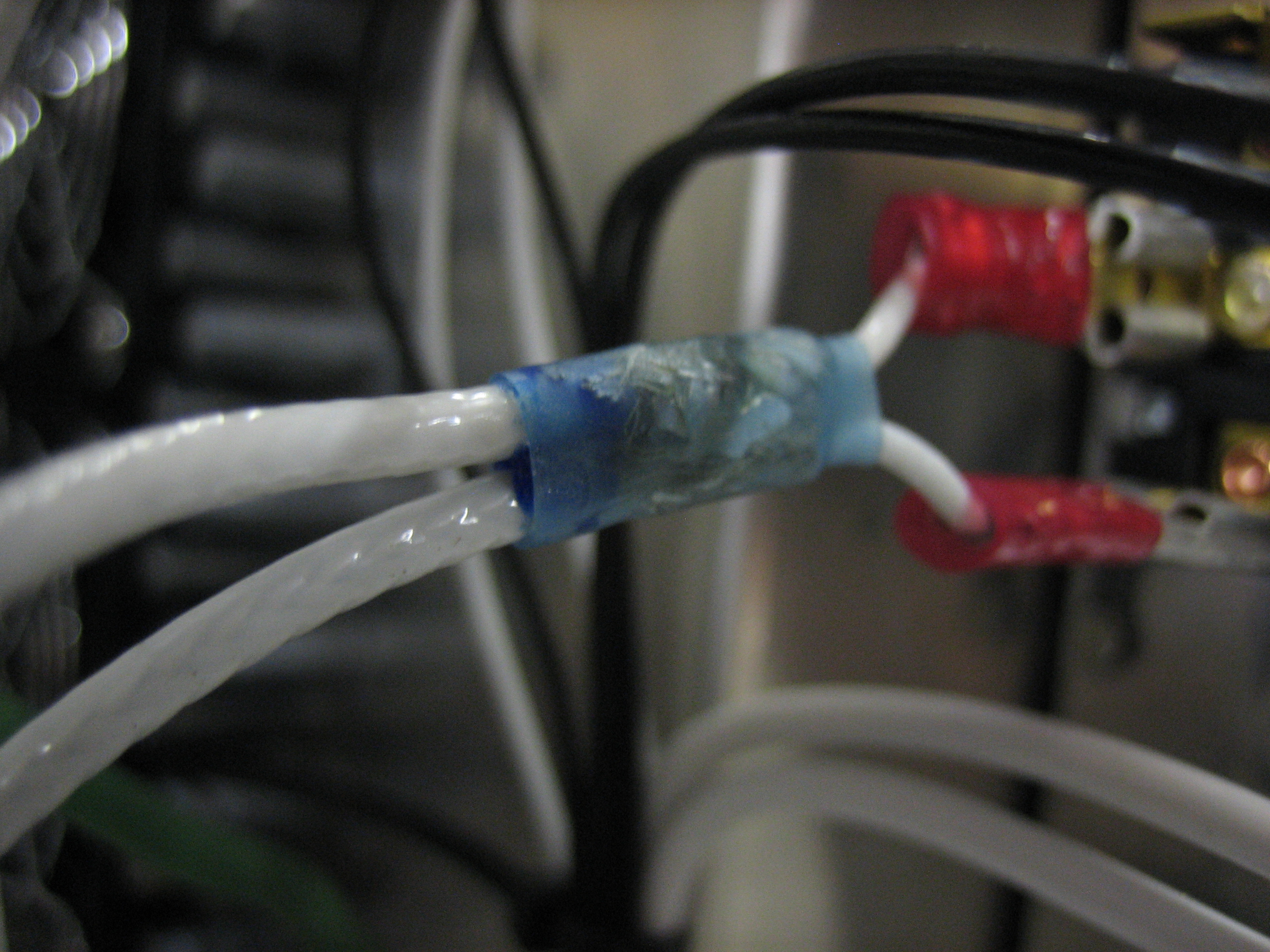
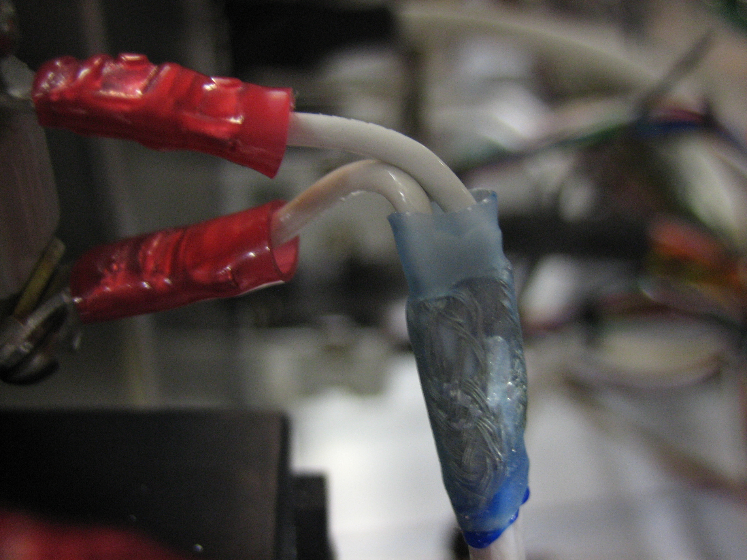
I received another order from Aircraft Spruce with some 18AWG shielded wire. The piece that came with the electronic ignition wasn’t long enough to run from the unit to the switch, then to the breaker, and finally to the battery bus. I used a solder sleeve to join the shields of two pieces and then connected their center conductors to the NO side of a 1-3 switch.
From the switch, the wire runs to the breaker where a similar connection is made.
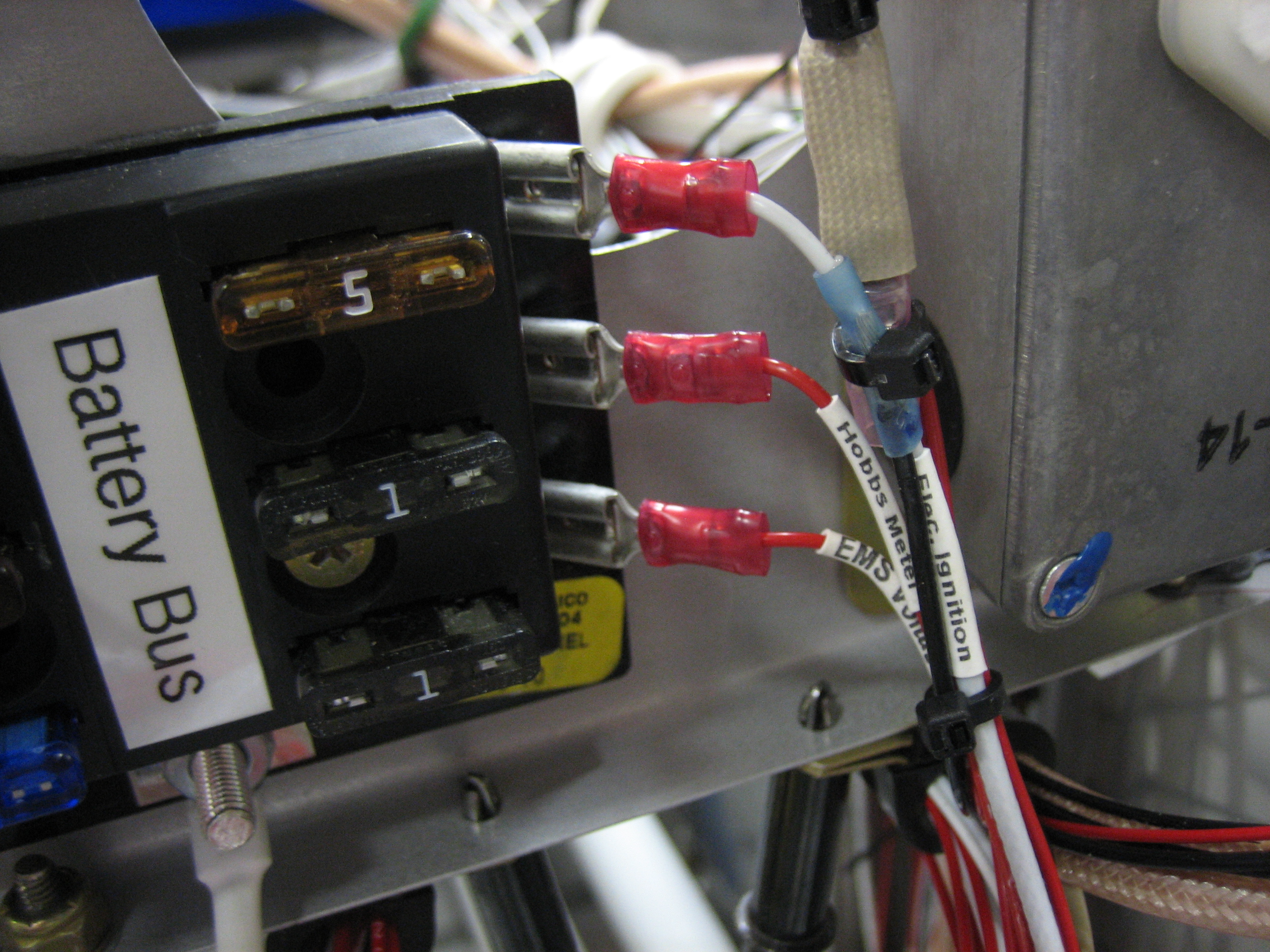
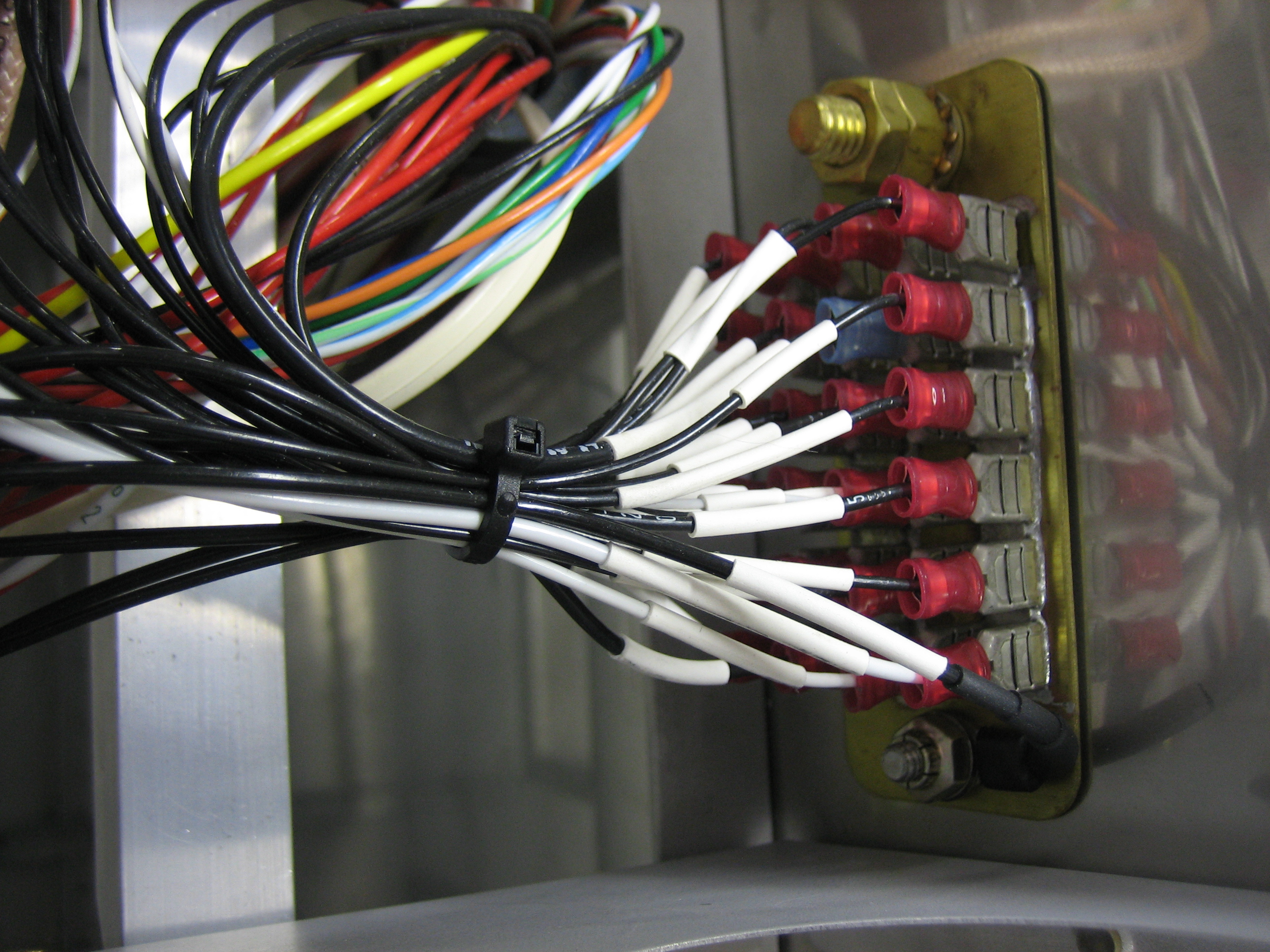
The center conductor of the shielded wire is connected to the battery bus (the upper right fuse here). Another solder sleeve is used to connect an 18AWG black wire to the shield. The installation manual specifies that this should be directly connected to the battery, but I’m trying to limit unprotected wires in the aircraft as much as possible. Connecting this here adds only a couple of connections over the recommended wiring method, and these are very high-reliability connections.
That black wire then runs to the ground block. I drilled a hole through the firewall to anchor the other end of the ground block and attached the wire there. I doubt this is significantly more reliable than one of the fast-on connectors, but it’s about as reliable a connection as you can make short of connecting it directly to the battery ground terminal.
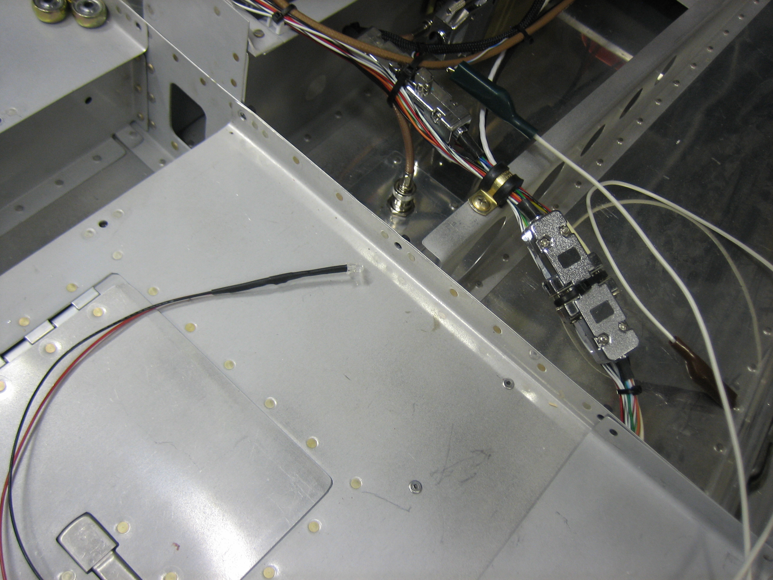
I had a little more energy, so I quickly fabricated the ELT data verification circuit and hooked it up to the wire that I left sticking out of the ELT connector. I fired up the avionics and verified that after the GTN had acquired a GPS fix, the light started flashing about once a second to indicate that the ELT was receiving valid position data.