I drilled both lower side hinges to the cowl.
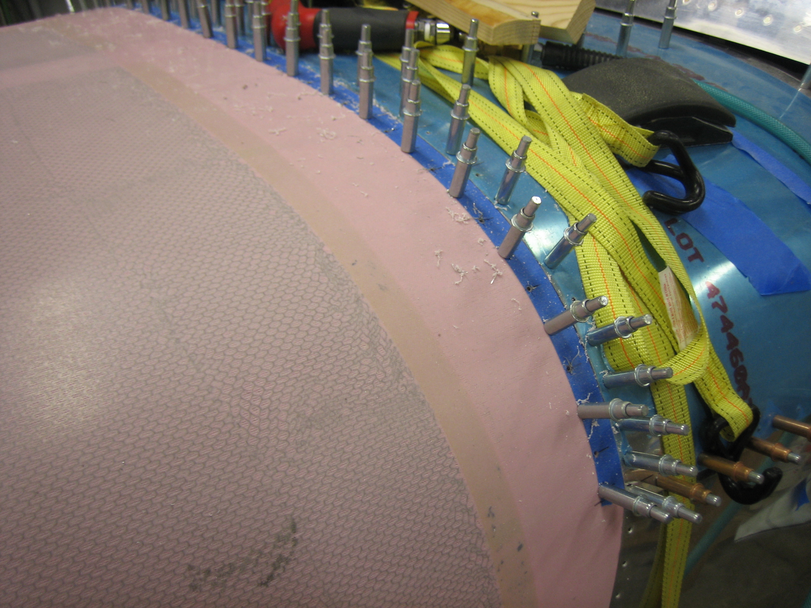
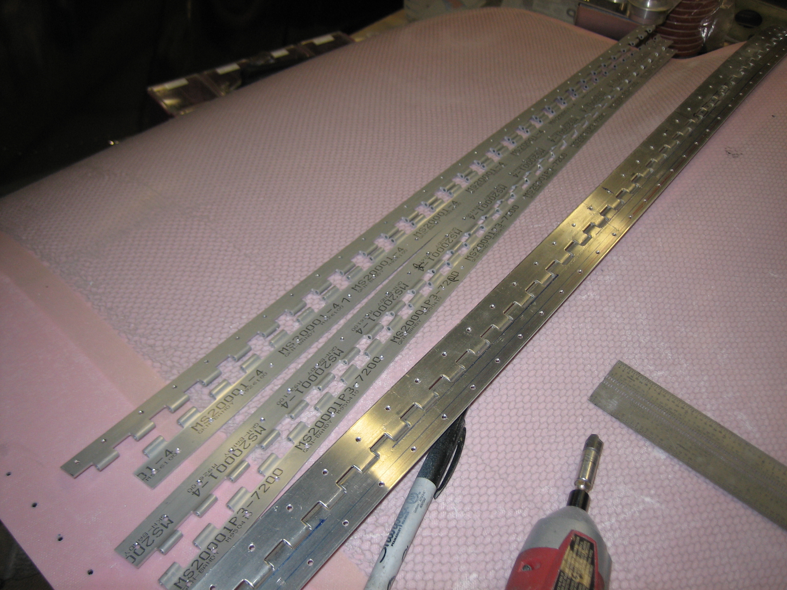
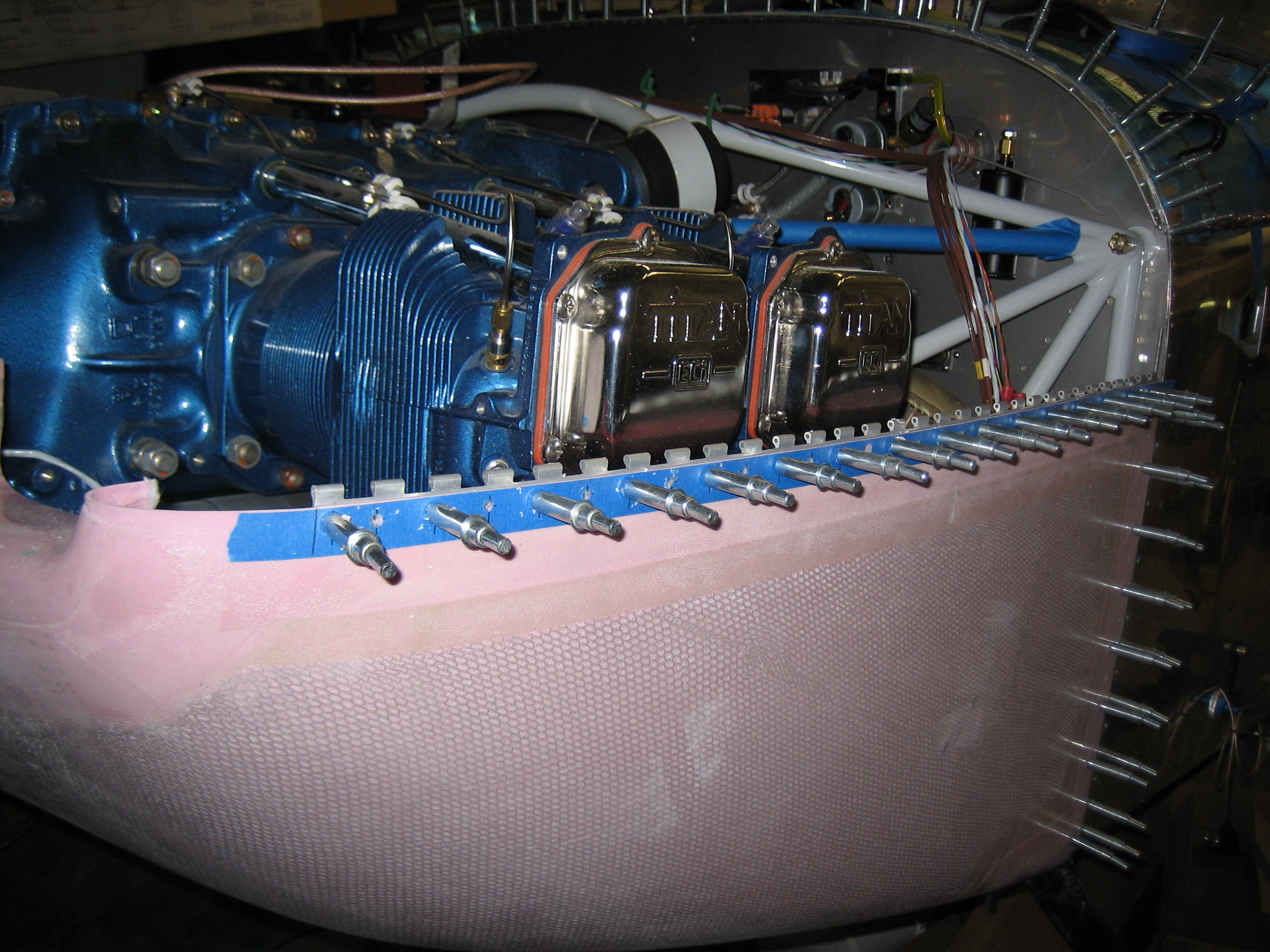
I then clamped a section of MS20001P4 hinge to the lower cowl on the left side and laid out some holes on approximately 1″ centers.
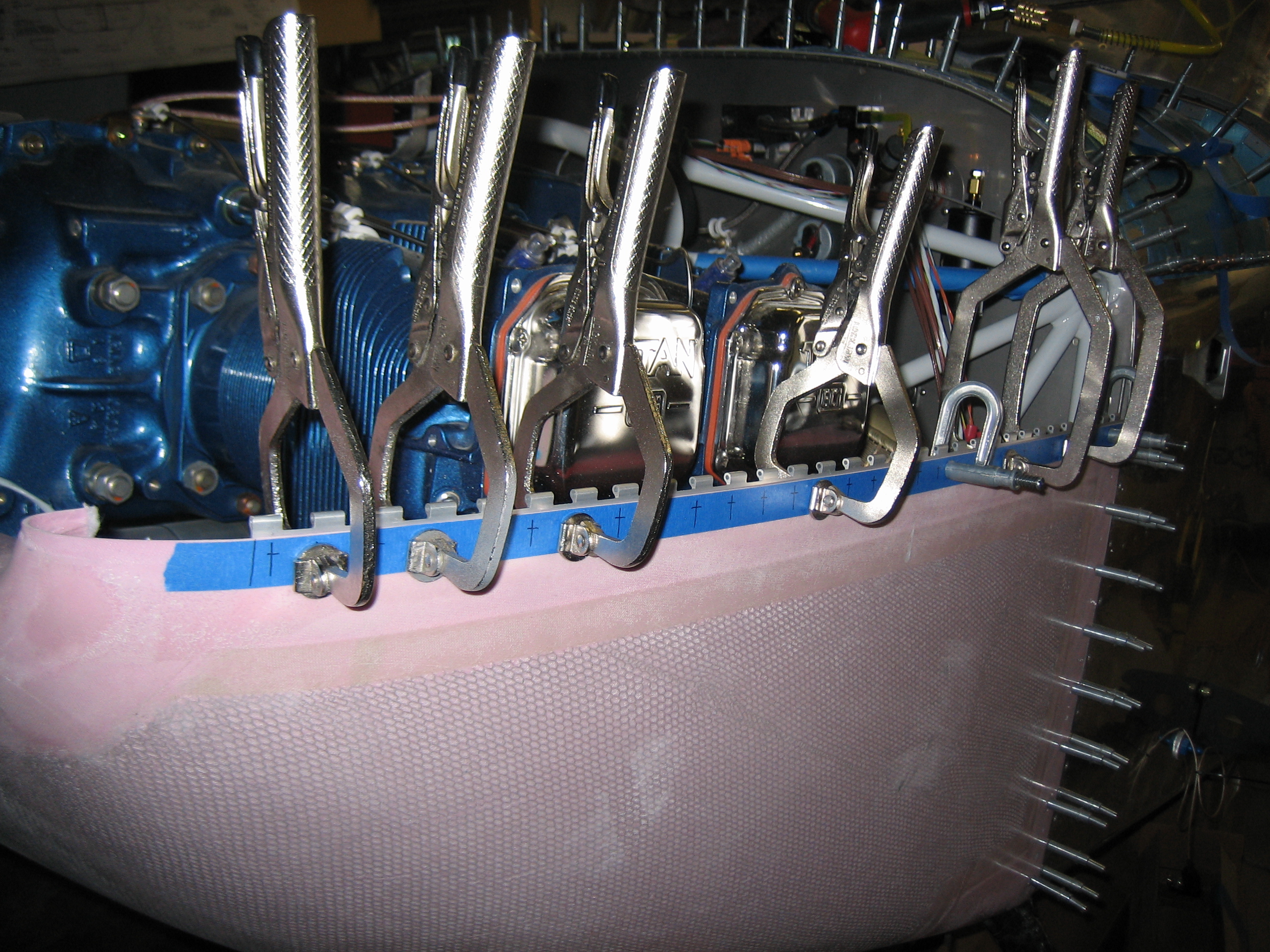
I then drilled all of the holes.
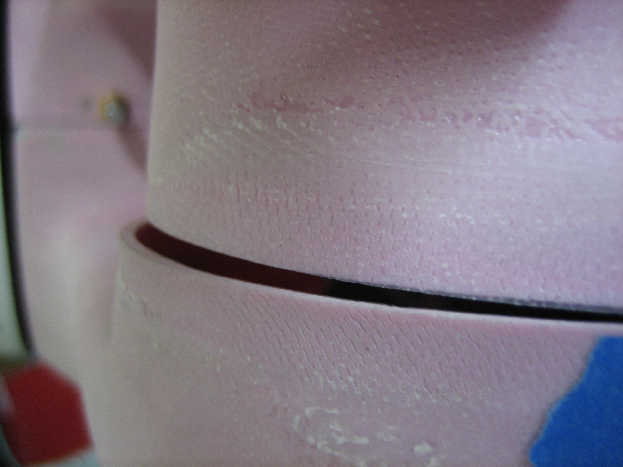
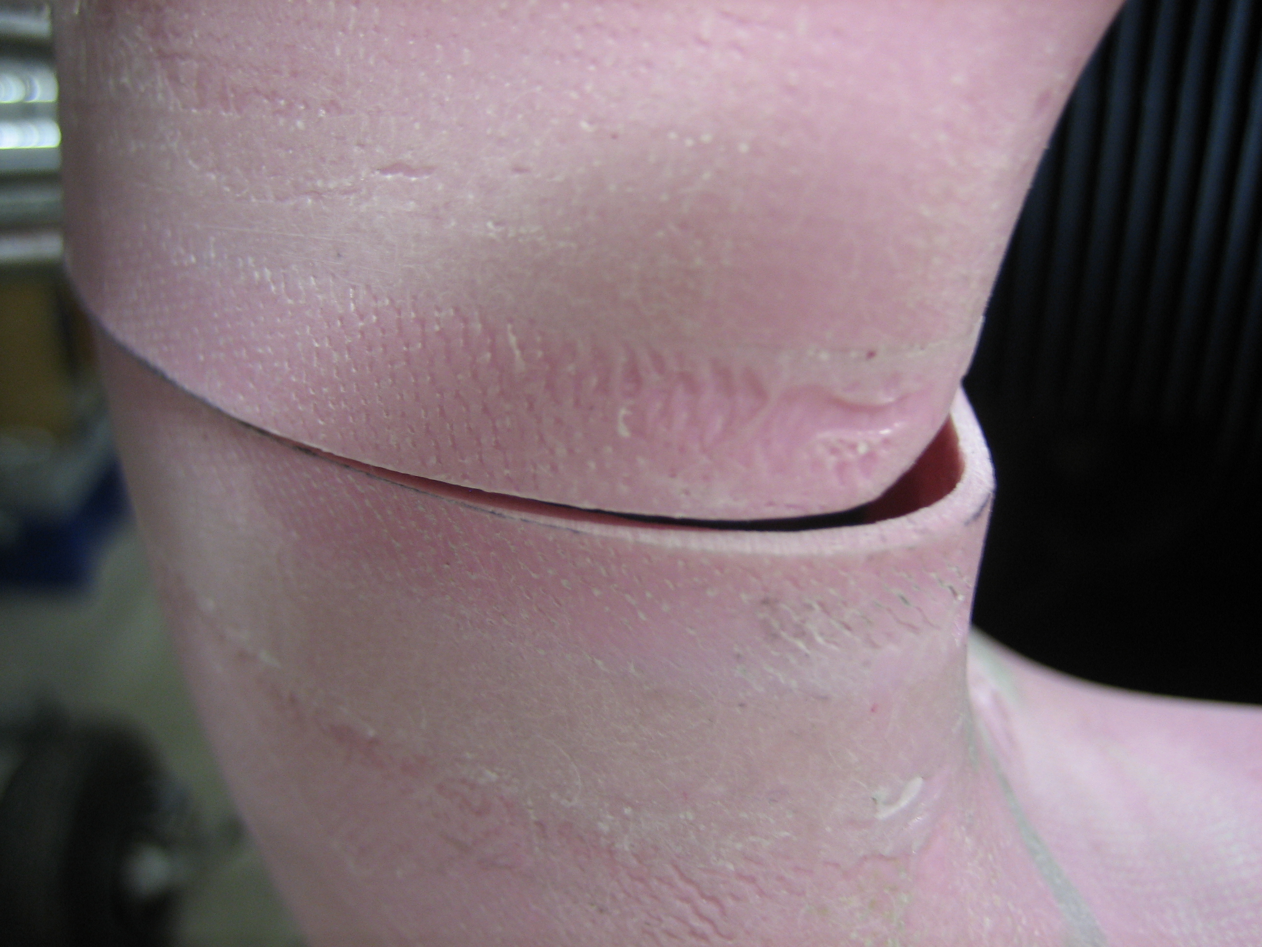
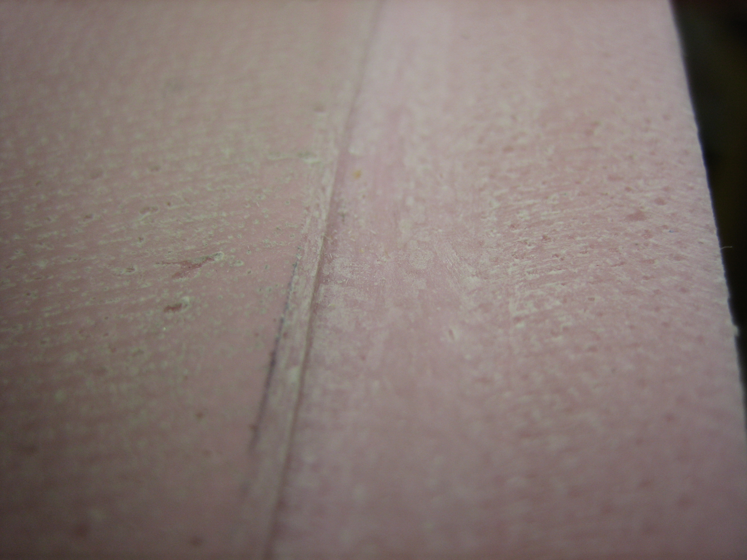
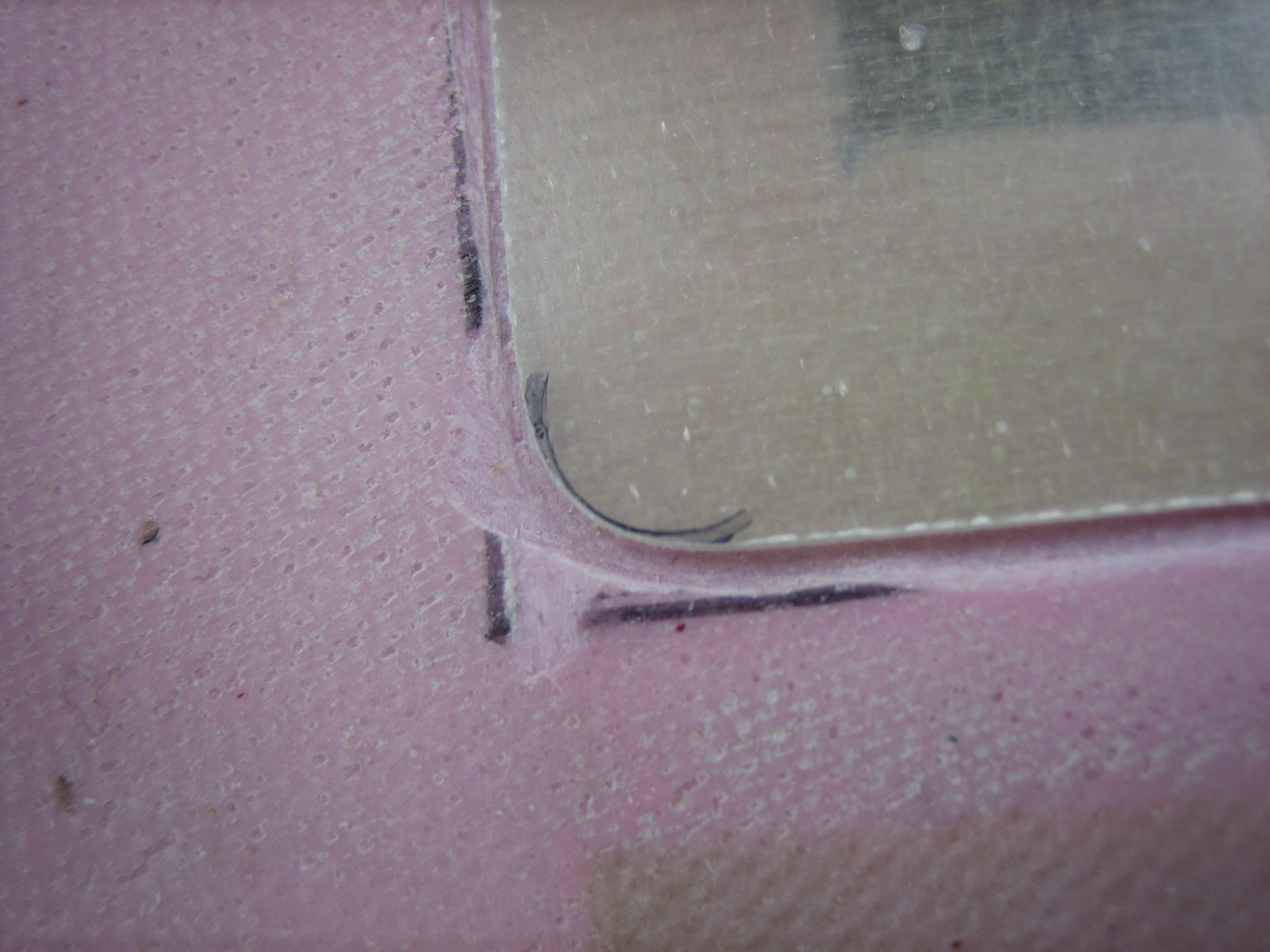
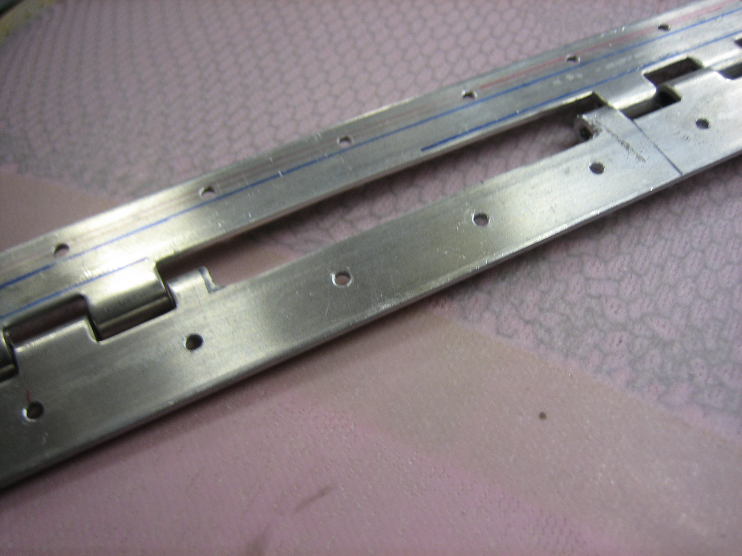
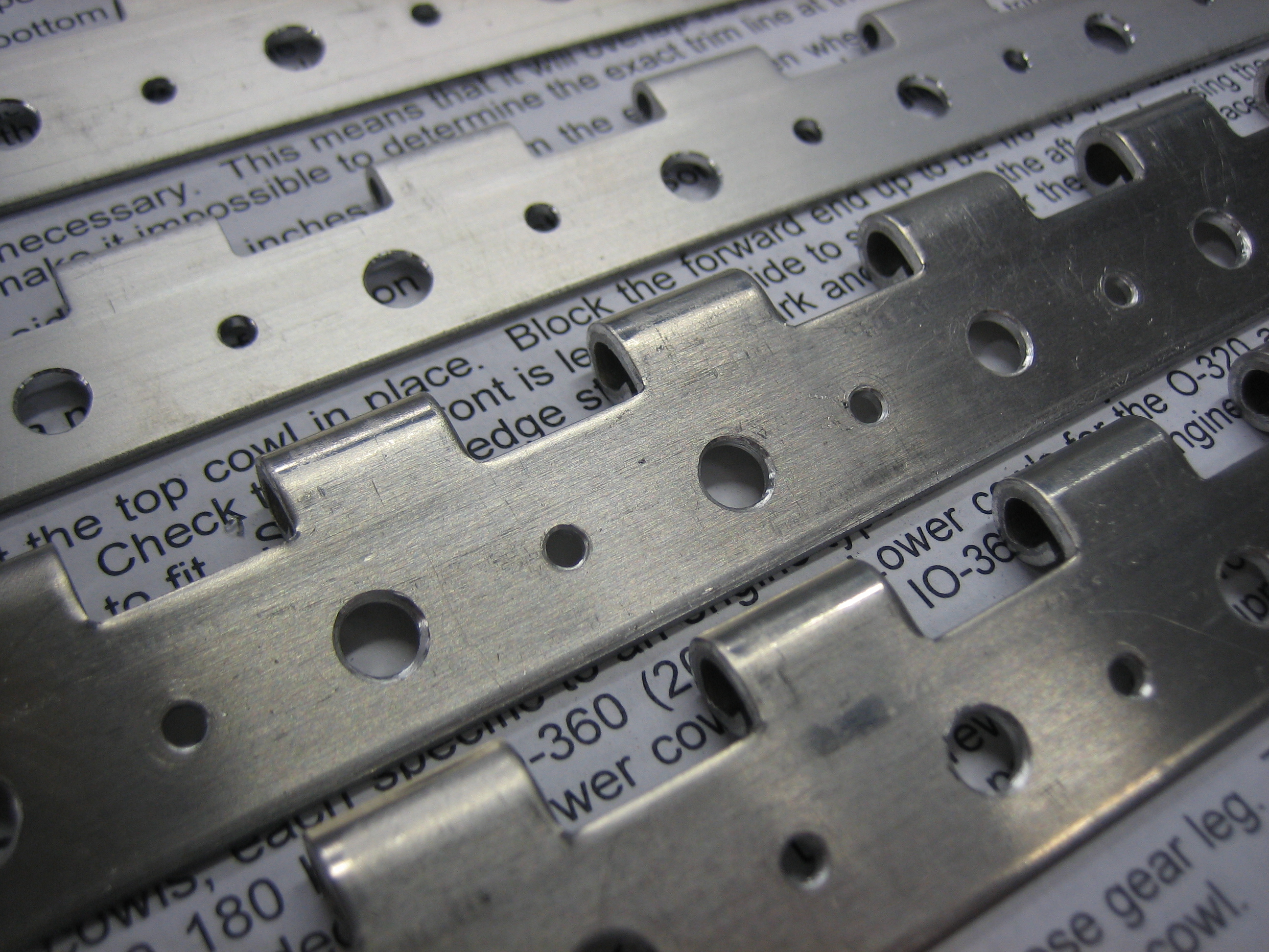
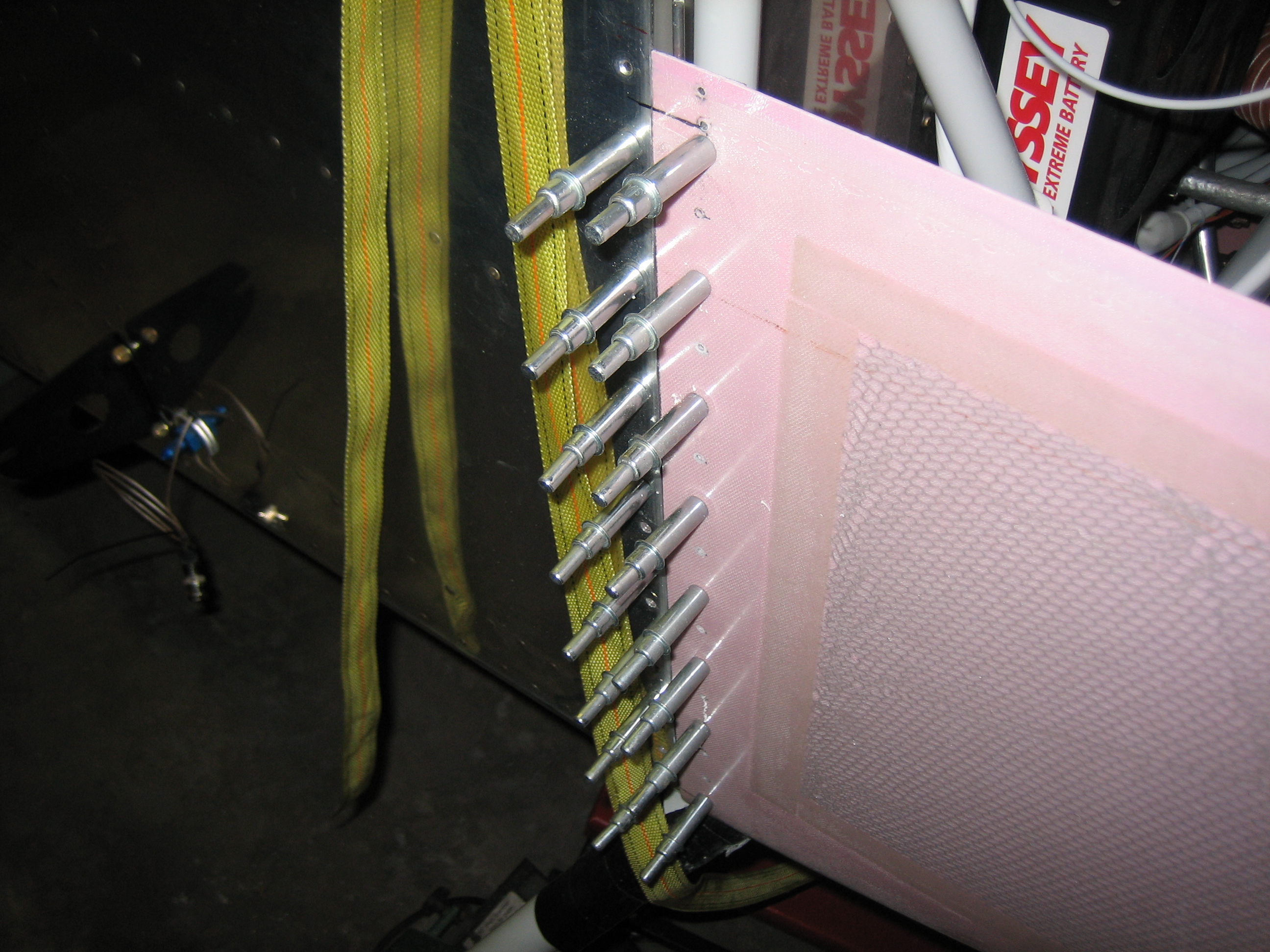
Here’s a closeup of the joint. I’m using MS20001P3 on the upper half since I don’t need the extra width. I installed the P4 on the lower half so that I could bias the hinge up enough to have a small strip of solid hinge material at the joint line. Doing it the way the plans specify would mean that you would be able to see the hinge ears through the joint which looks pretty crappy.