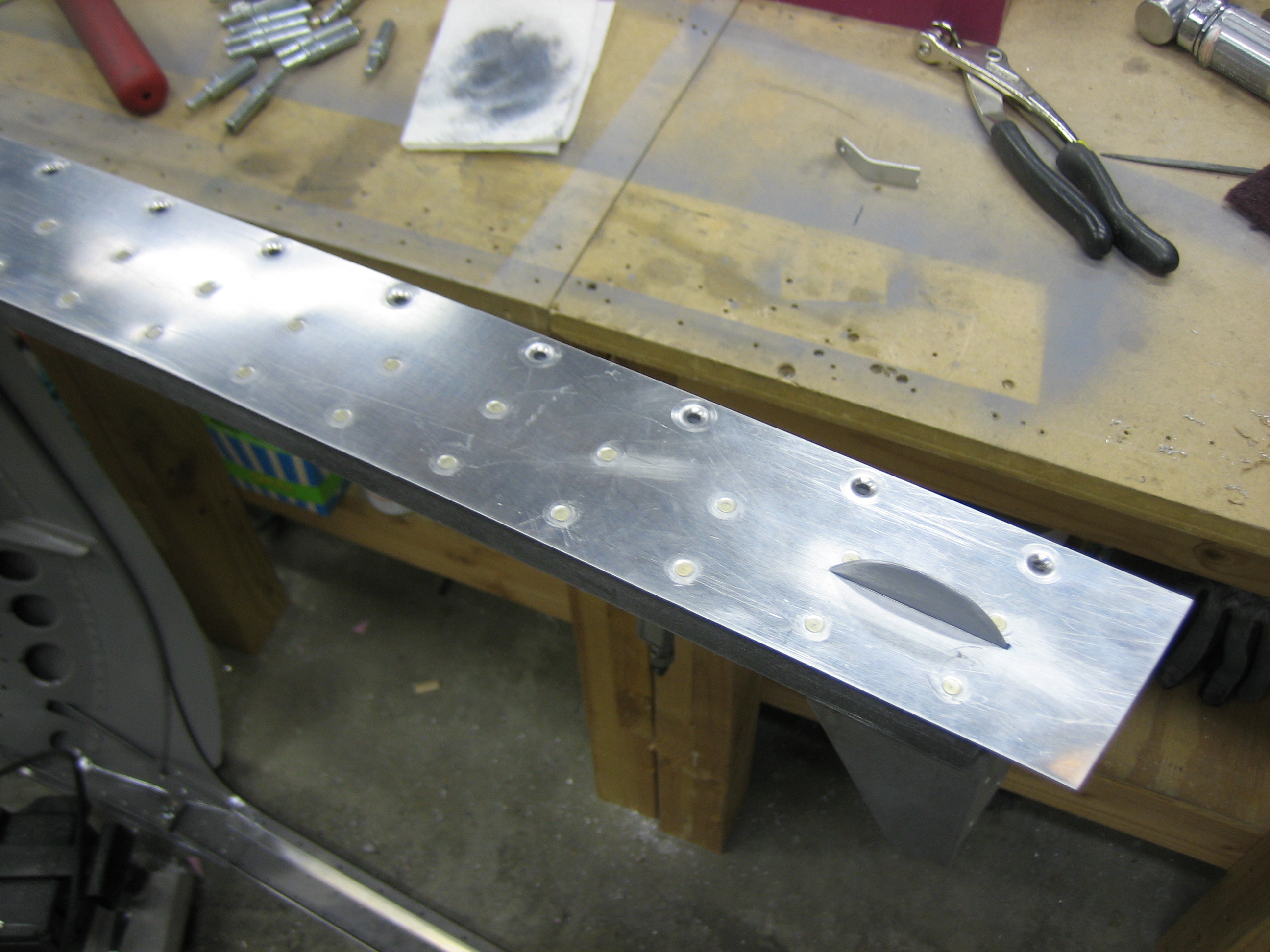
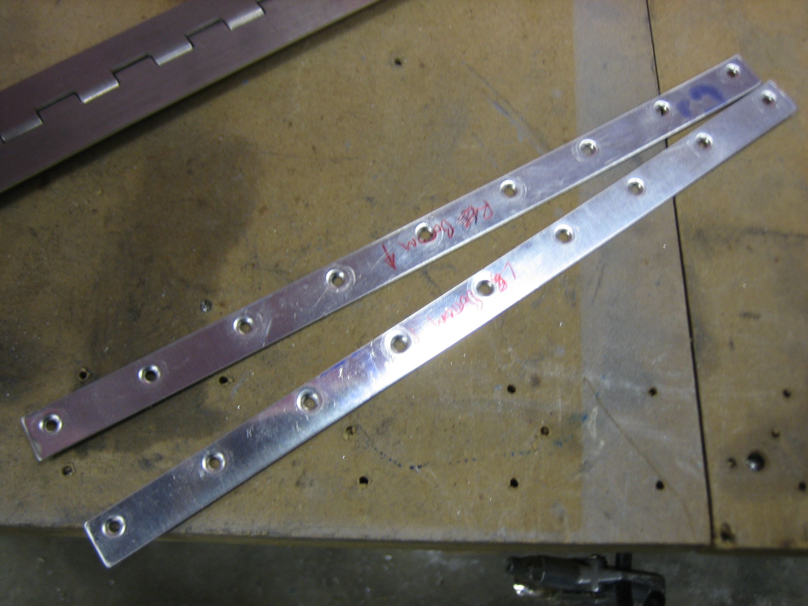
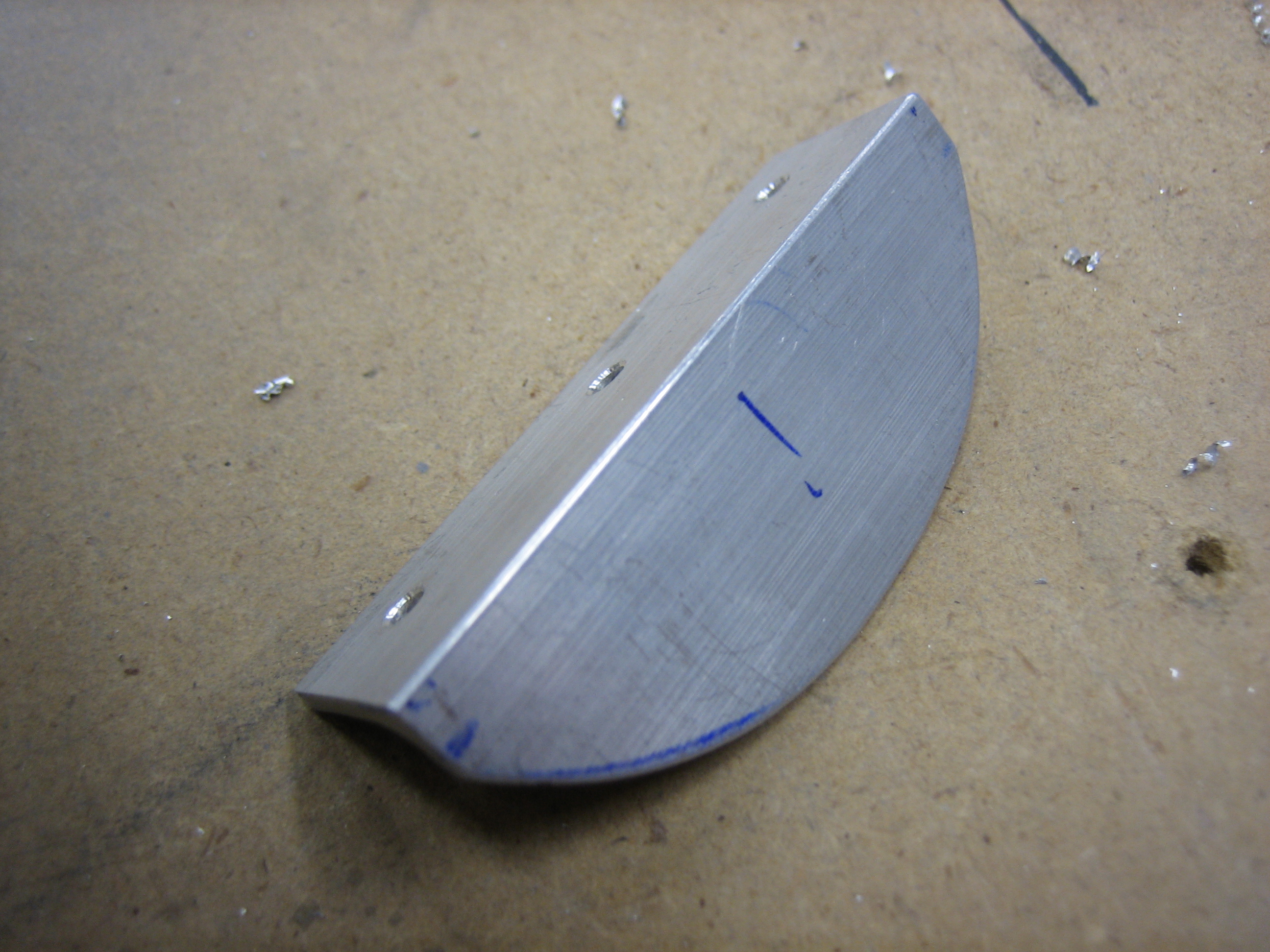
I fabricated the exhaust stabilizer strap tonight out of some aluminum angle that I cut one leg off of. I primed and painted it and will install it tomorrow. This ties each pair of pipes together at the back end so that they all move as a unit.
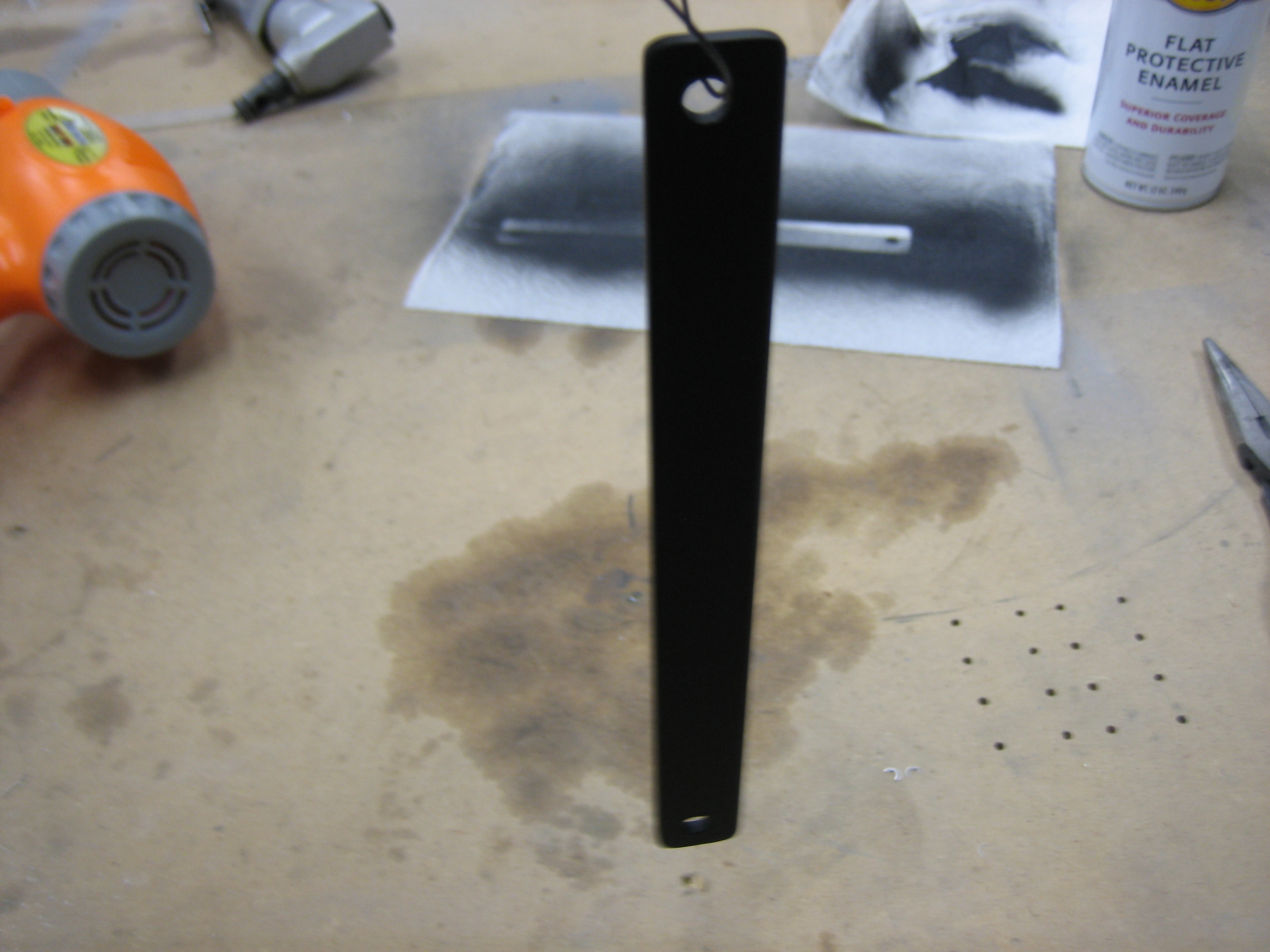

I fabricated the exhaust stabilizer strap tonight out of some aluminum angle that I cut one leg off of. I primed and painted it and will install it tomorrow. This ties each pair of pipes together at the back end so that they all move as a unit.
Dynon and Vertical Power this morning announced that the SkyView system will be supporting the VP-X. After seeing the VP-X at Oshkosh last year, I decided to defer working on the electrical system as long as possible in the hopes that this will happen. Thanks guys; this combination is going to rock!
Here’s the announcement from Dynon:
http://www.dynonavionics.com/docs/news_VPX_announcement.html
It’s a little disappointing that they’re charging an additional $275 for this given that they’ll almost certainly sell more SkyView systems as a result and because every other avionics supplier is including it for free. Dynon products are already priced much more aggressively than their competitors though, so I’m not going to complain too loudly.
Here’s an overview of the VP-X:
http://verticalpower.com/vp-x/
After working through the load planning, I’ll be going with the VP-X Pro. Using the VP-X should not only simplify wiring, it should provide substantial new features to the electrical system as well as advanced fault detection.
Now, if Garmin would just announce a replacement for the GNS-430…
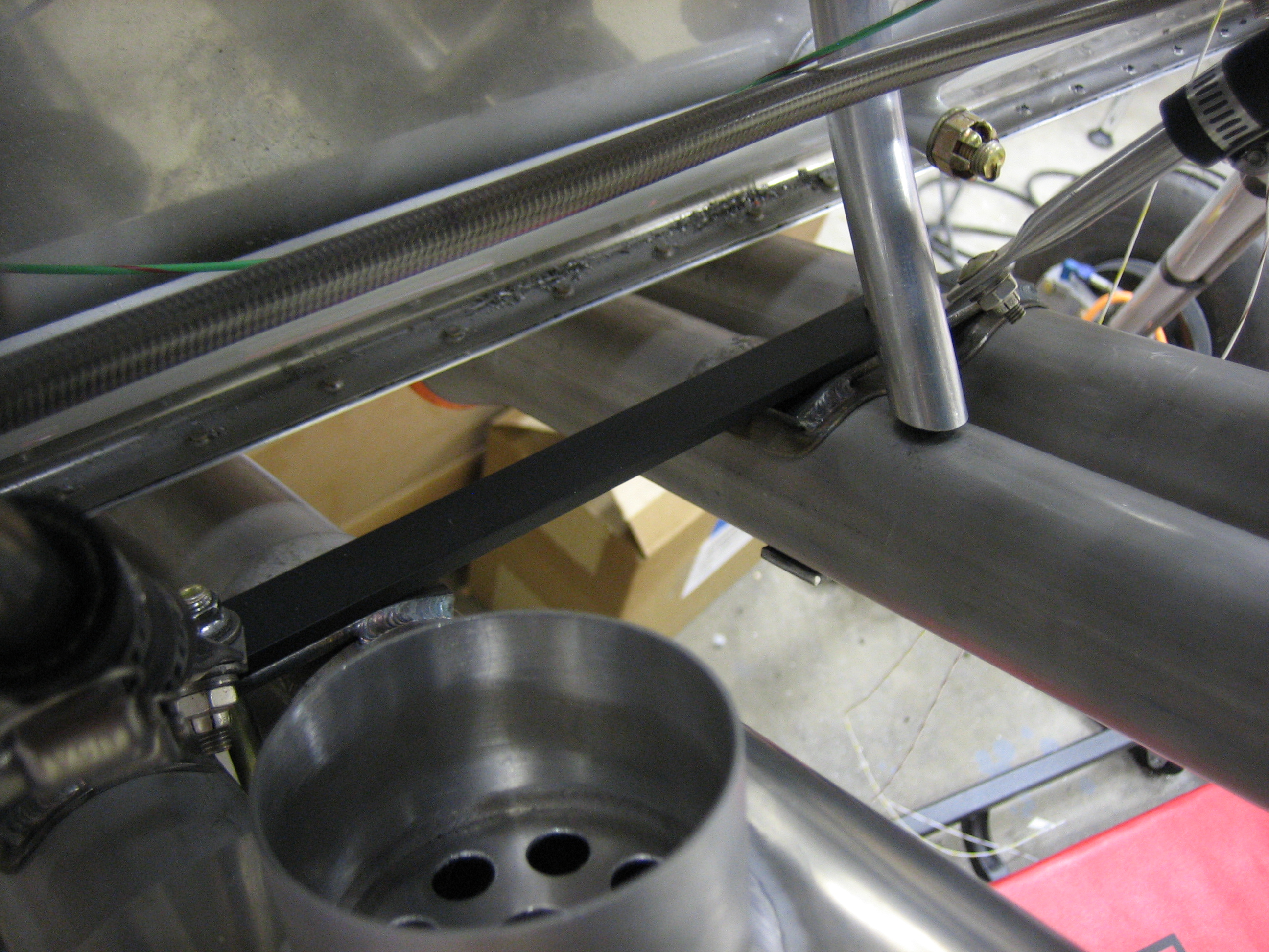
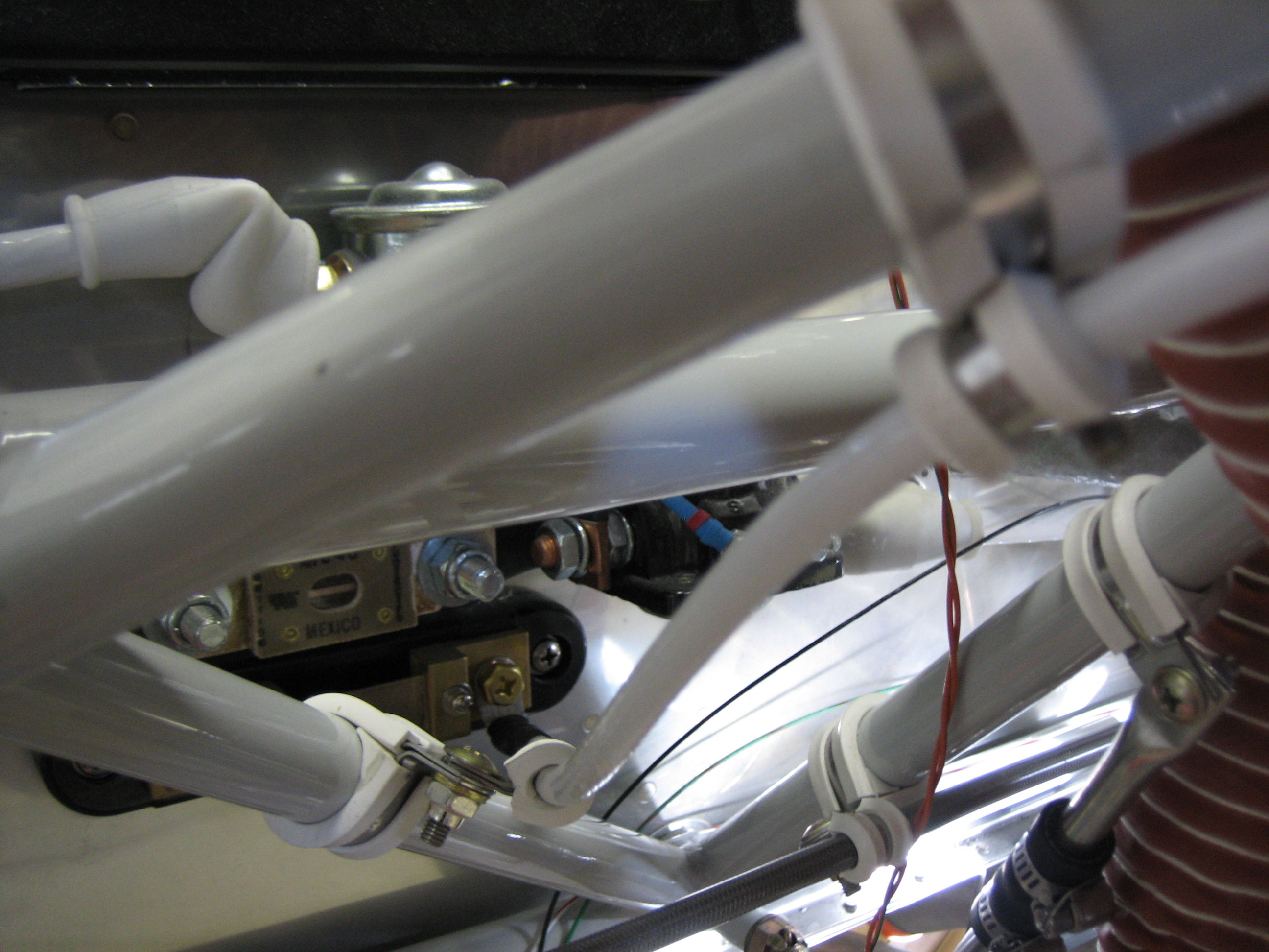
I installed the exhaust stabilizer strap that ties the two pairs of exhaust pipes together. This significantly stabilizes the exhaust pipes over just having each pair supported by on hanger.
Construction work is slowing down on the plane a bit while I’m working on the electrical system design. The VP-X is fairly significantly different than the architecture specified in the Aeroelectric Connection. I’m reworking most of the schematics and still trying to decide how I’m going to handle backup circuits for several devices.
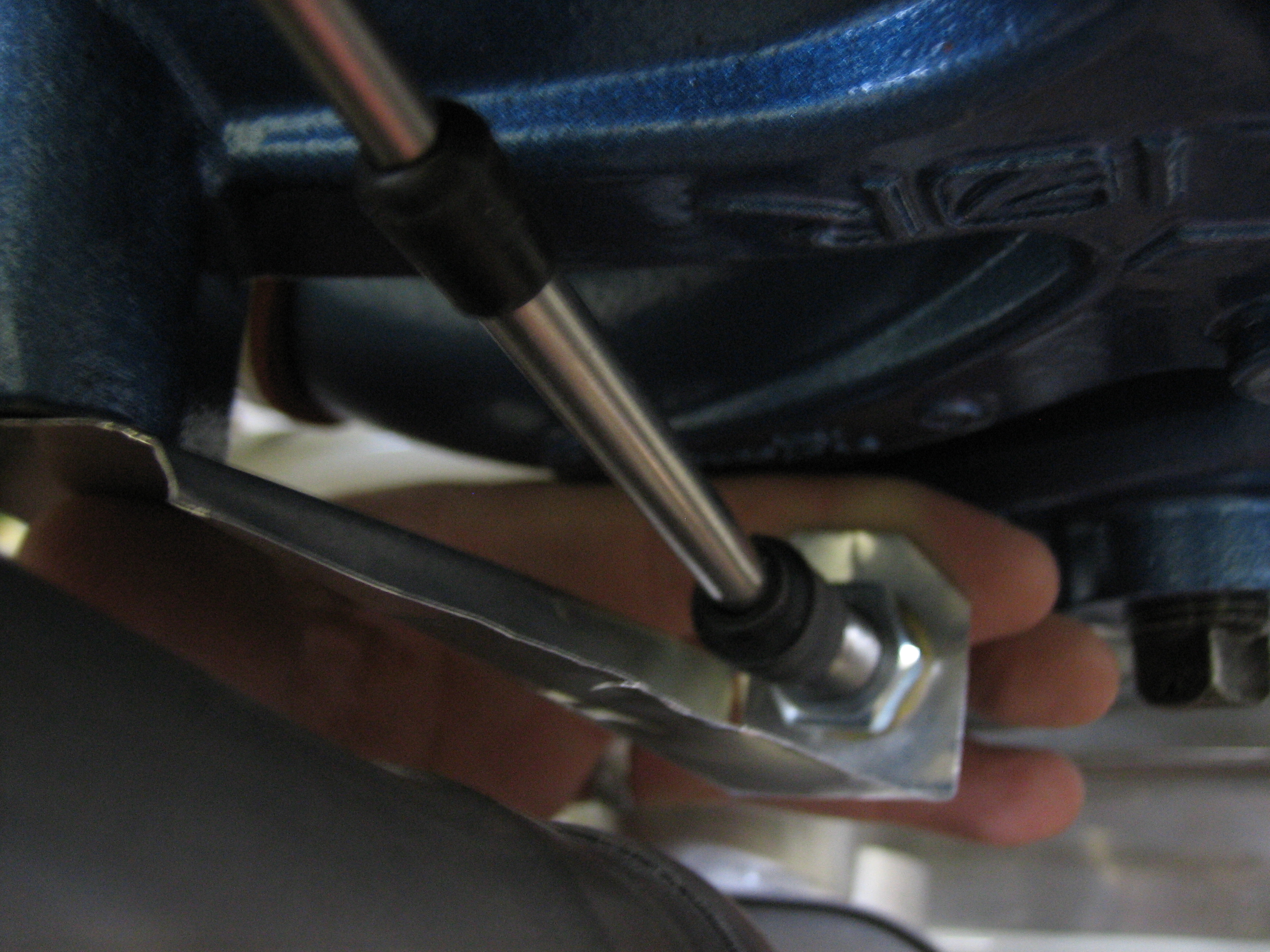
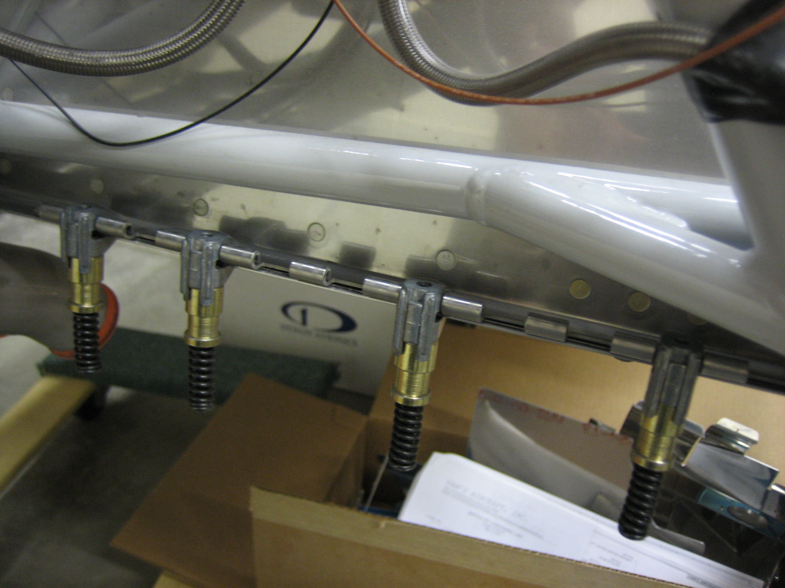
The stock throttle bracket that Van’s supplies doesn’t work with the Superior sump since the attach point is in a different location. I’m going to fabricate a custom bracket out of some 16 gauge steel (the same thickness as Van’s bracket). I used some really thin (0.004″) aluminum flashing I had on hand to mock up the bracket. This puts the cable on a direct path to the hole in the firewall and keeps it well clear of the exhaust and sump.
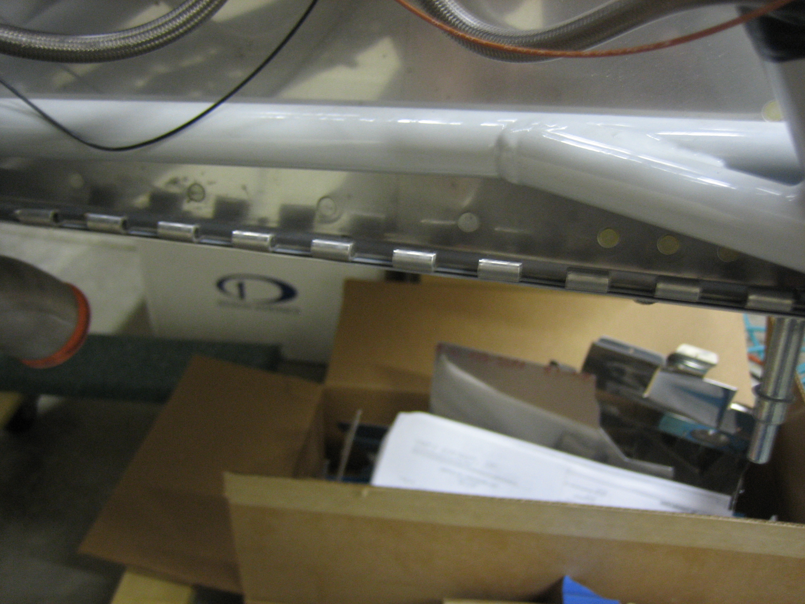
Here’s a shot from slightly lower in case that makes it more clear.
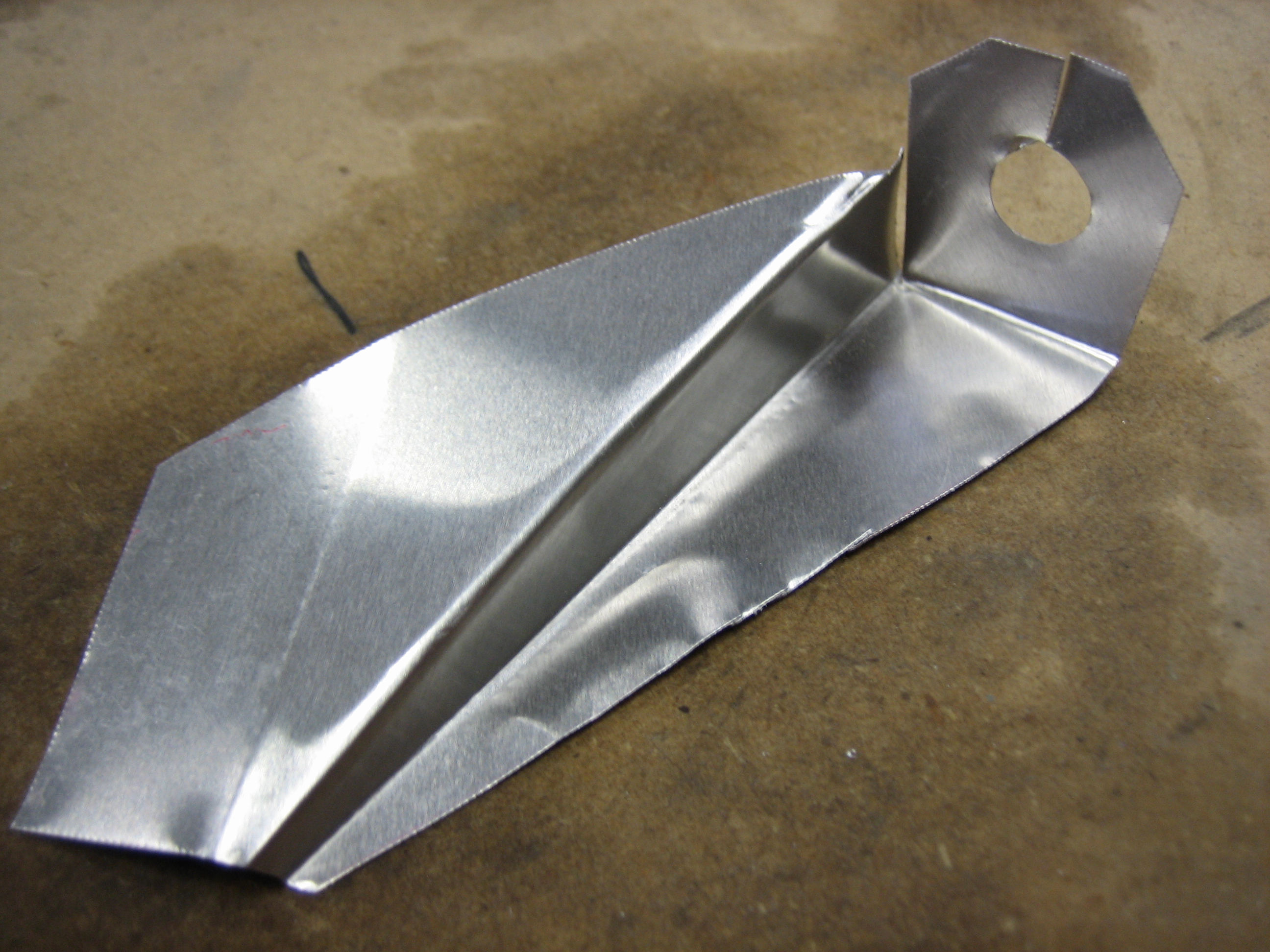
Here’s what the rough bracket looks like. I unfolded this and traced the pattern onto some 16 gauge stock I picked up from Home Depot. Cutting it out will be easy, but I’m still not quite sure how I’m going to bend this.
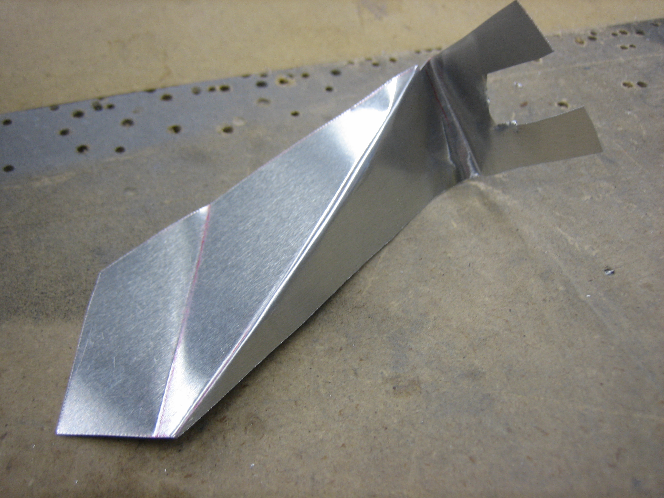
The throttle bracket that I mocked up a couple of days ago had an extra bend that was unnecessary and I couldn’t figure out how to bend it using the tools I have. Instead, I mocked up a simpler bracket. The slot on the end was only to make it easier to fit while mocking it up.
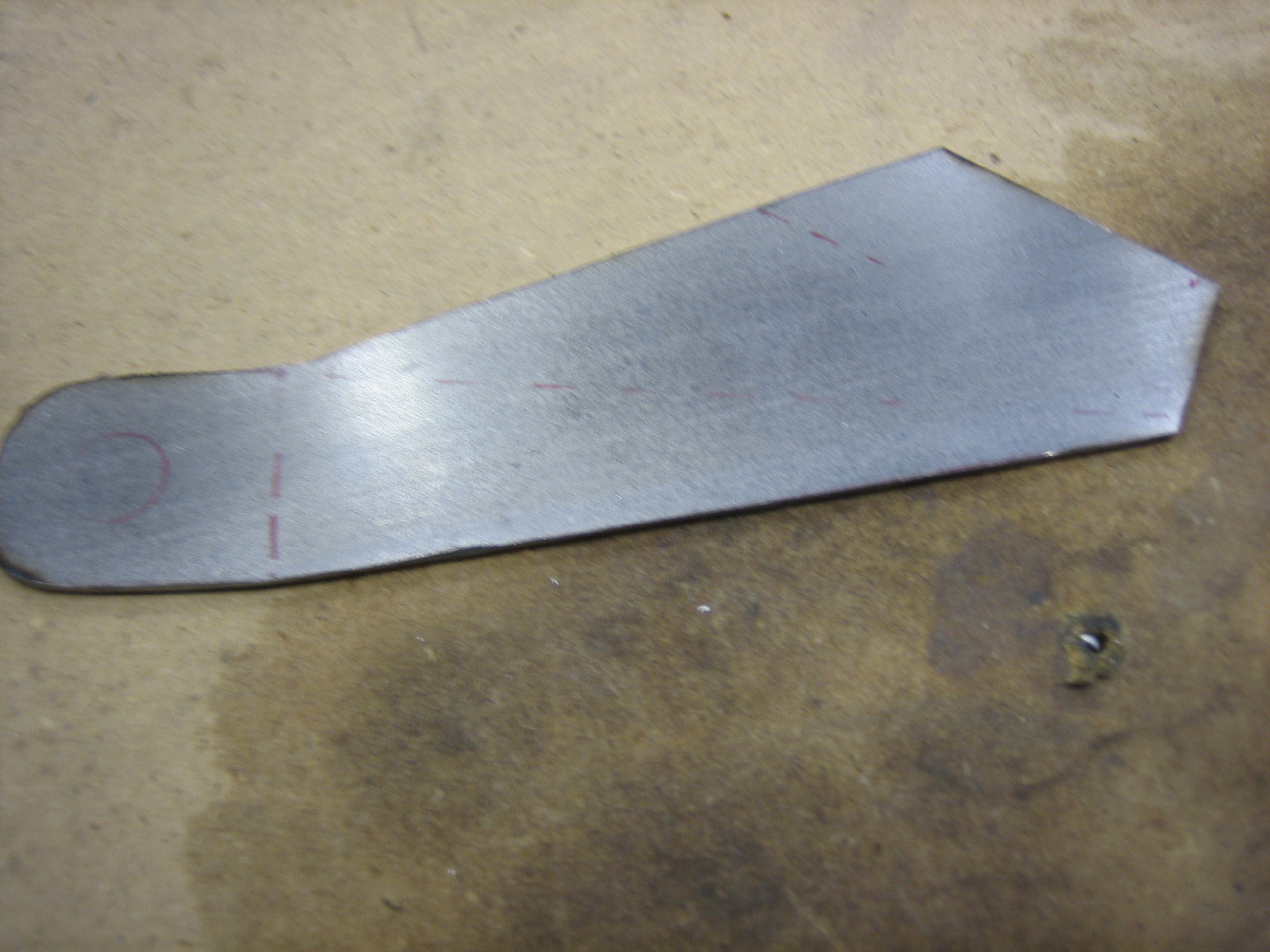
I unfolded the prototype and transferred it to a piece of 16 gauge steel.
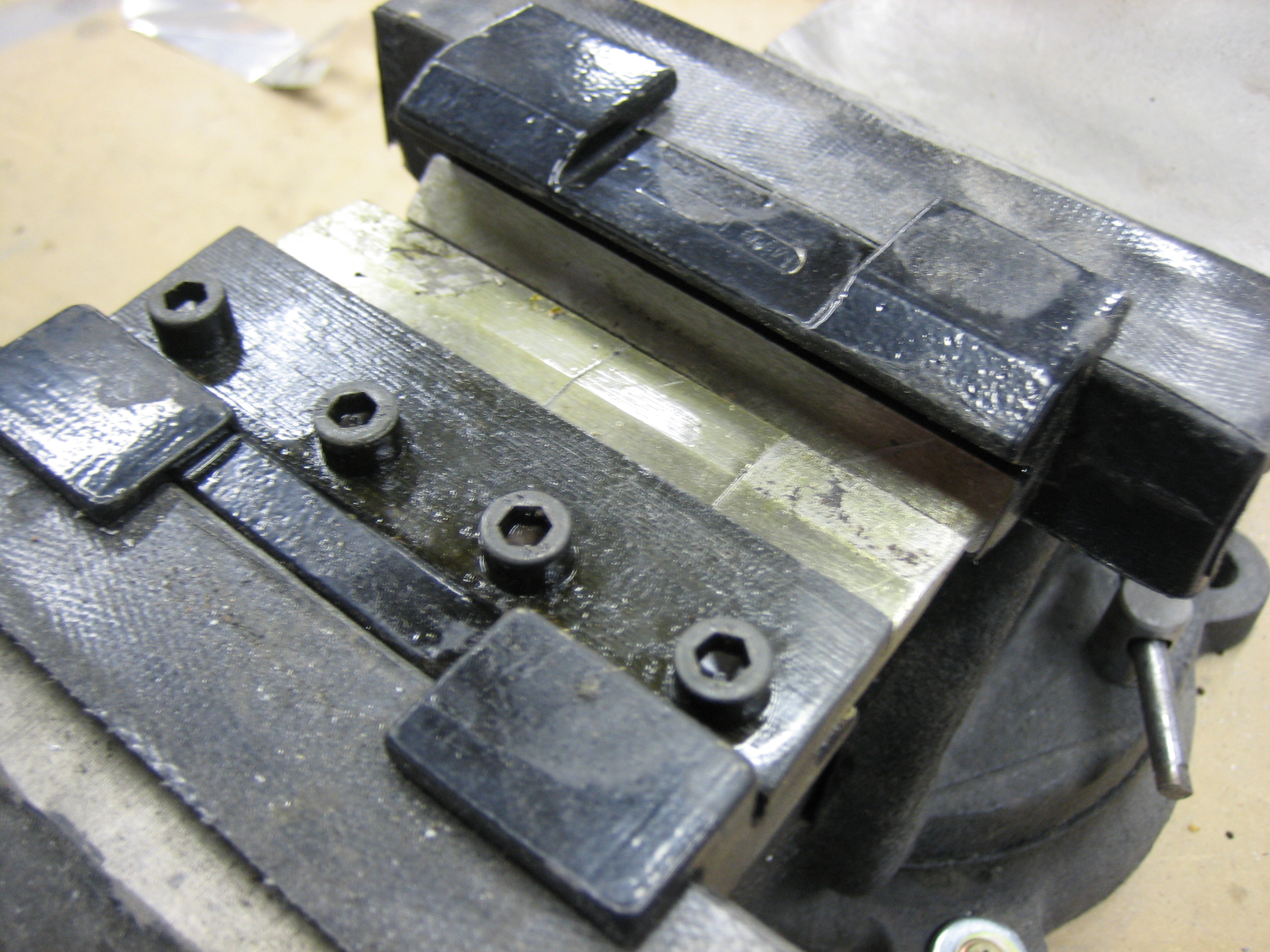
I marked out the bends and bent them using this vise brake that I borrowed from my dad. This thing had no problems bending 16 gauge steel.
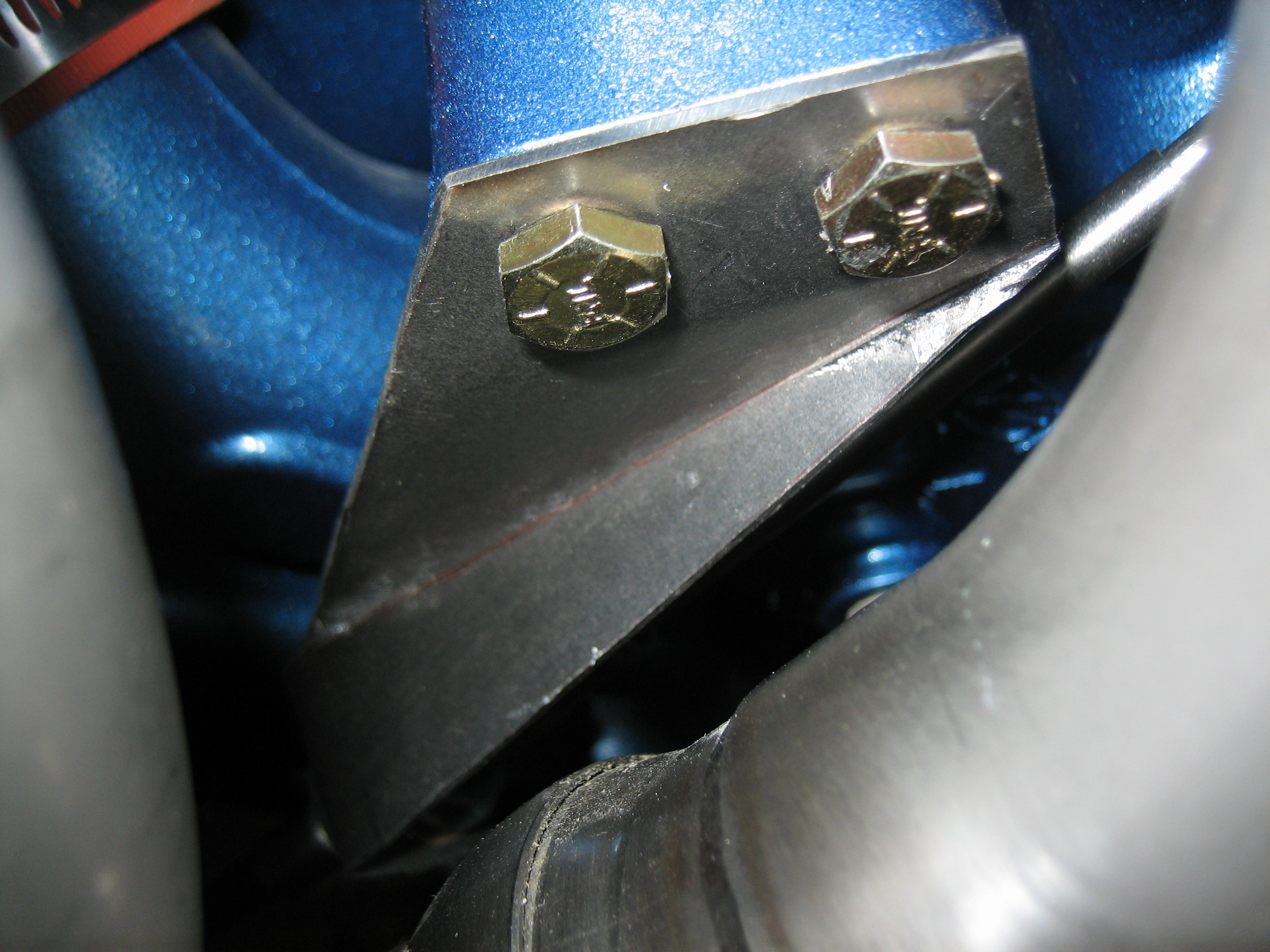
I drilled the mounting and cable holes and temporarily mounted it to the engine. Unbelievably, I absolutely nailed it on the first try. The 1/4″ mounting holes perfectly lined up with holes on the sump and the placement and angle of the cable hole was spot on.
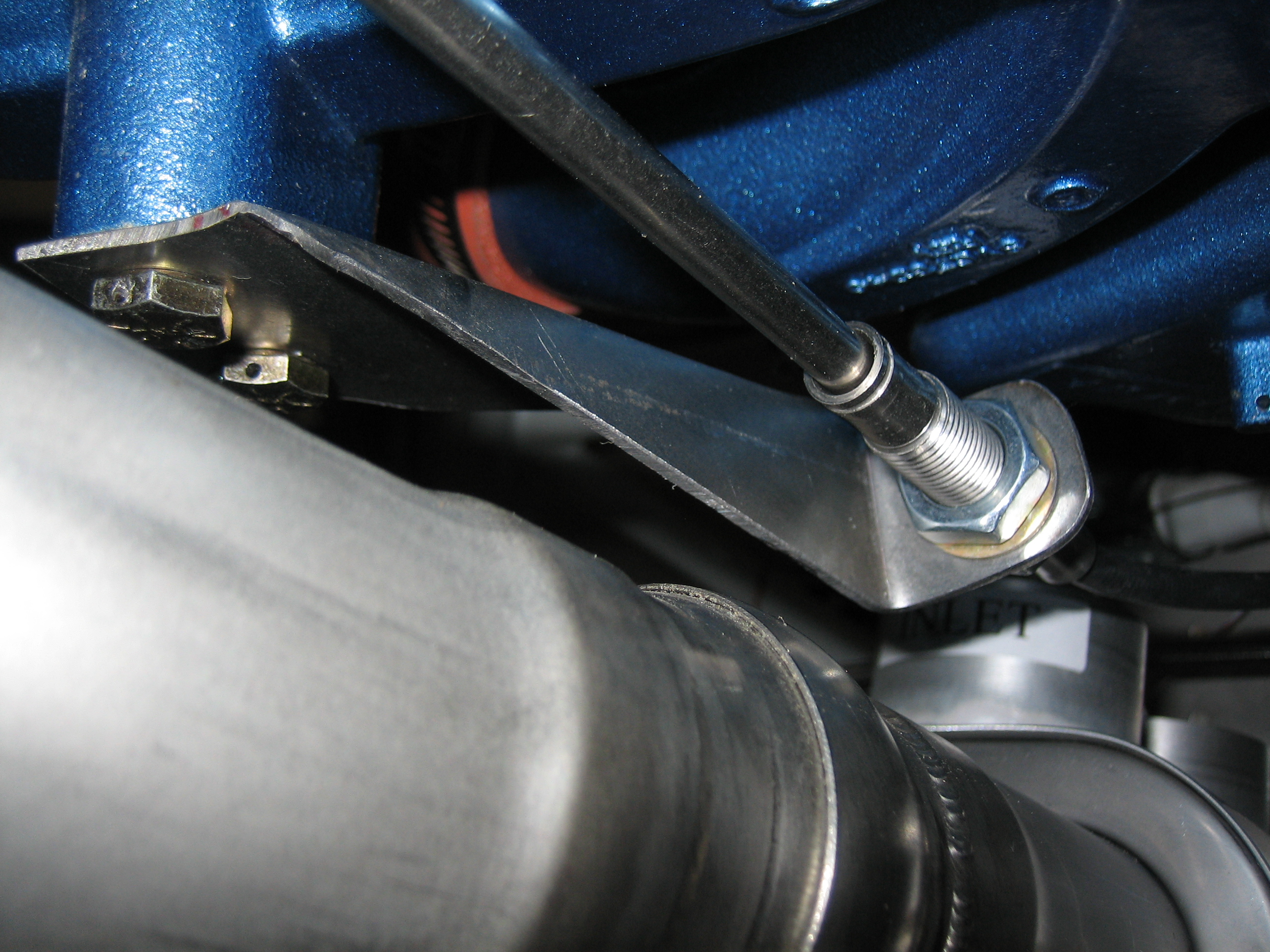
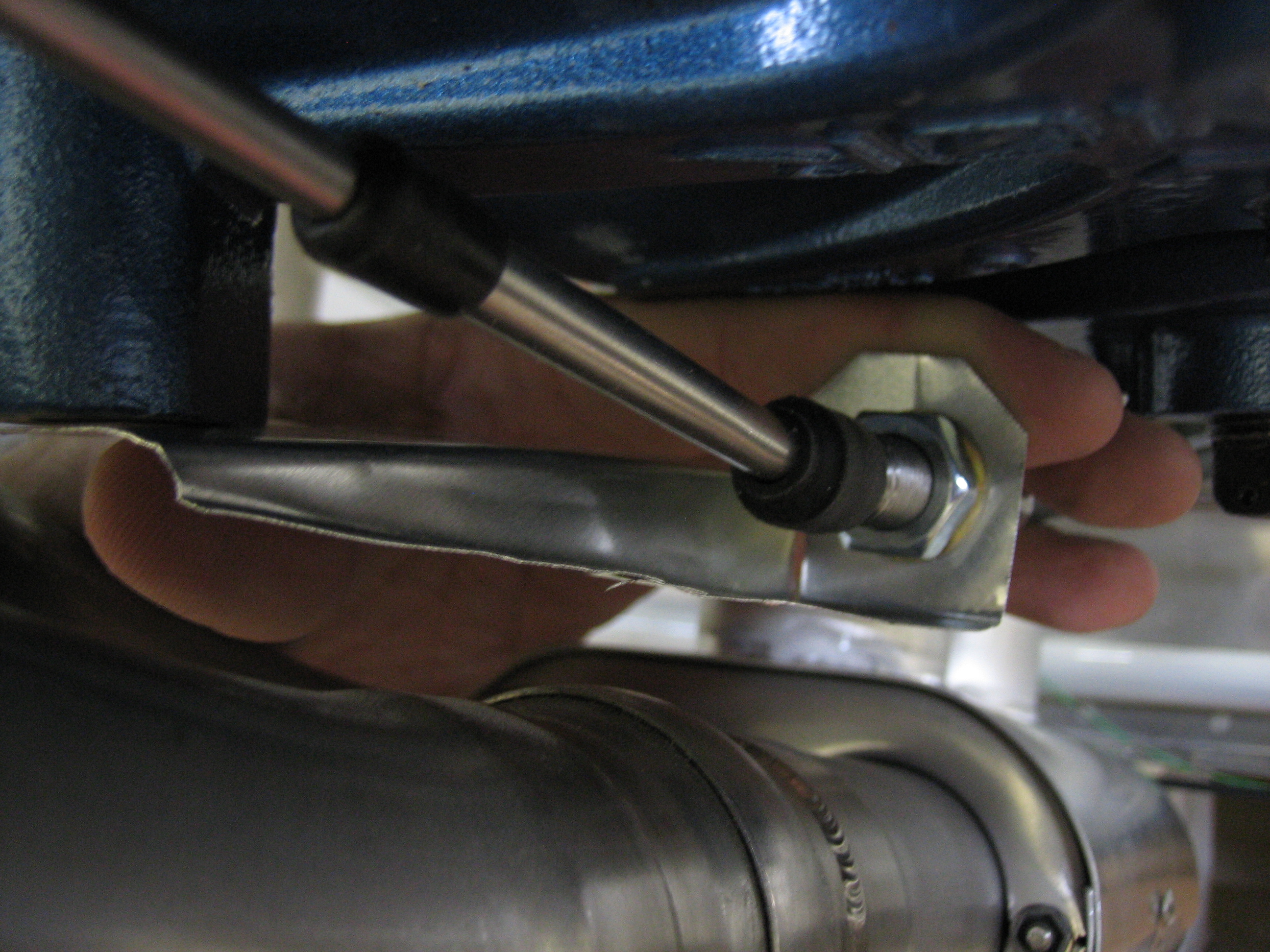
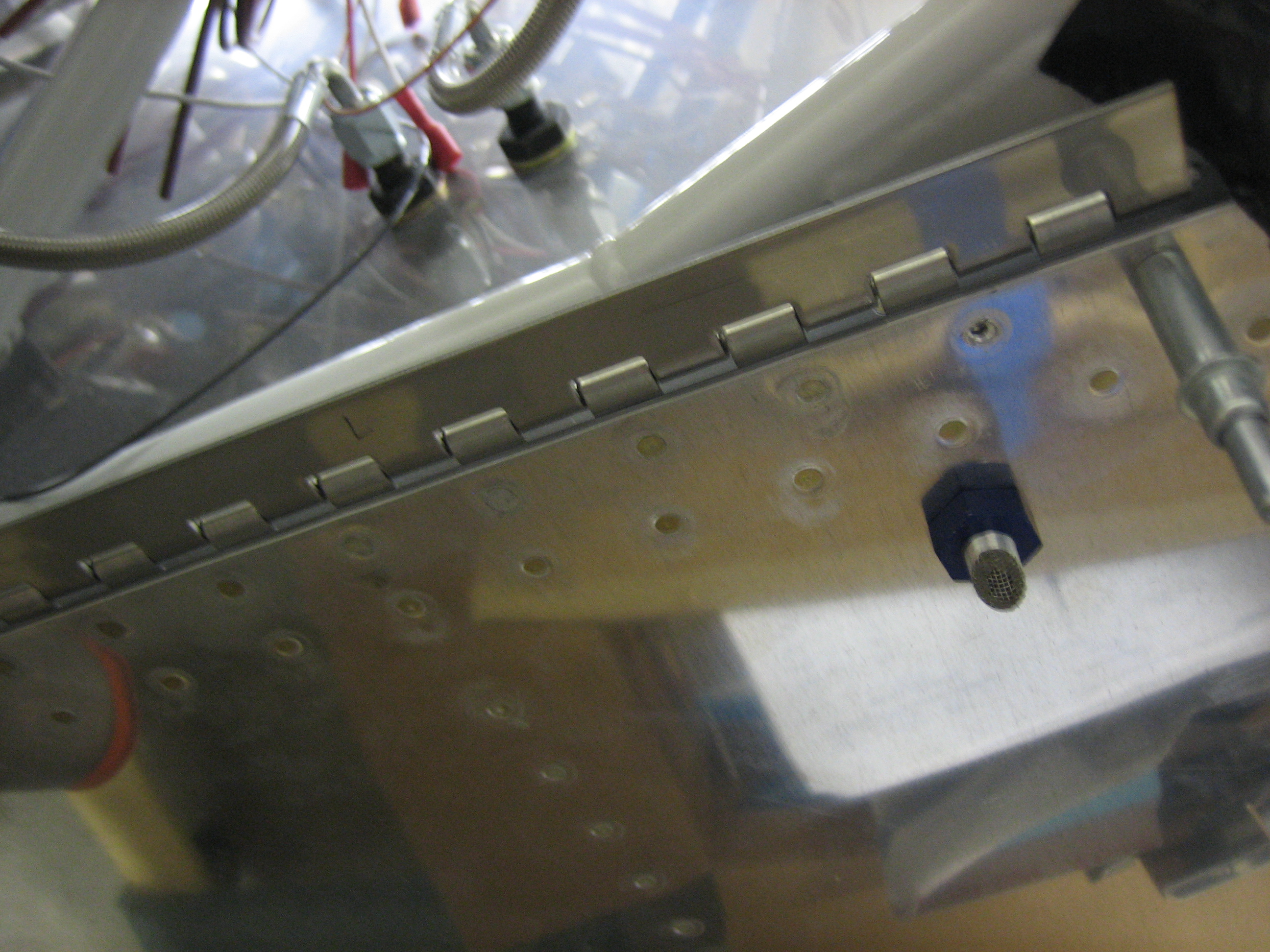
Here’s a closeup of the mounting end. This picture makes it look like it comes pretty close to the exhaust pipe, but there’s quite a lot of clearance.
After some adjustment, here’s the throttle in the full open position. Notice the slight gap between the nut behind the throttle nob and the friction control. This ensures that the throttle arm hits the stop on the fuel injection servo which ensures that you can reach full throttle.
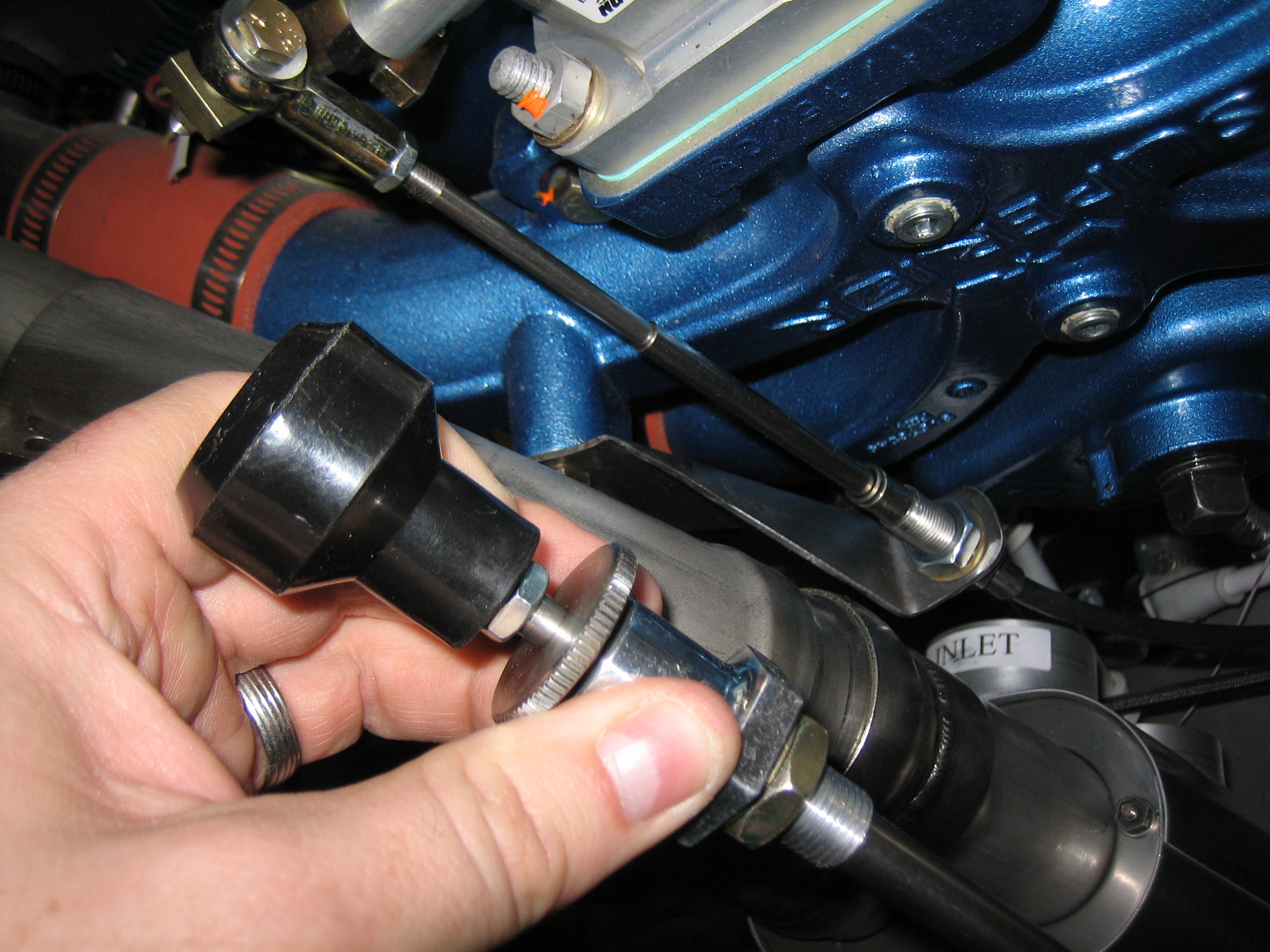
Here’s the throttle in the full closed (idle) position. Again, I’m hitting the stop on the fuel servo which ensures I’ve got the throttle fully closed.
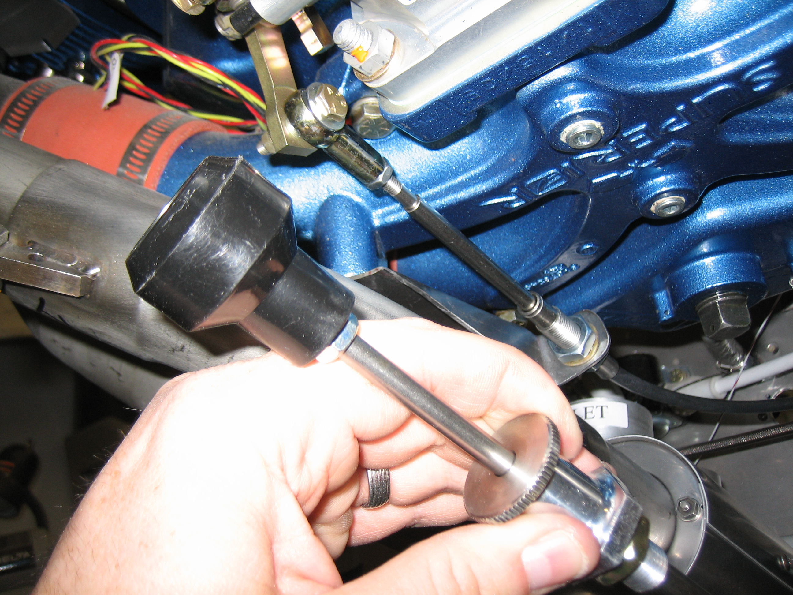
This is a poor picture, but it shows the alignment between the throttle cable and the hole in the firewall. It’s a perfectly straight shot back to the firewall from the bracket and clears the heat muff inlet by a 1/2″ or so.

Now that the throttle bracket fits correctly, I can clean it up and powder coat it before installing it for good.
I fabricated the 0.020″ spacers for the hinges that attach the bottom of the cowl to the firewall.
I got an email from Joe Blank at Van’s today. After reviewing my cowl fitting issue further, they now think my cowl is made correctly and that if I trim the aft edge all the way around, I should have enough overlap on the sides to make a straight joint.
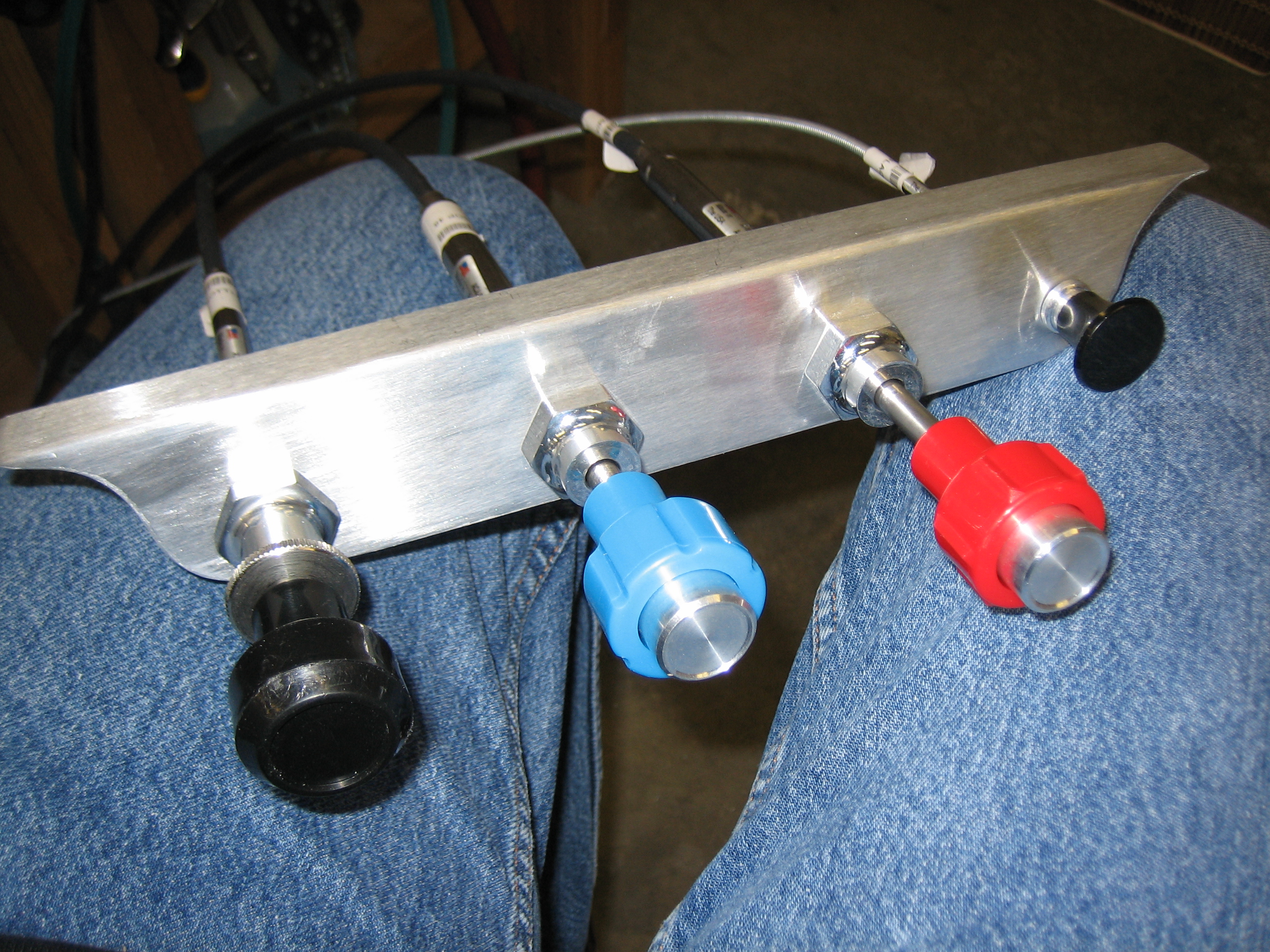
Anyway, tonight’s little project was to determine the mounting position for the control cables. I used the stock bracket that came with the kit to mock up a potential control spacing to see if there were any conflicts before drilling the actual bracket that I bought from Experimental Air. My original goal (and what I mocked up here) was to put the three engine controls in the center, the parking brake on the left and the cabin heat on the right. This resulted in 2″ between the outer knobs and the outboard engine controls and about 2 7/16″ between each of the engine controls. After playing with it for a few minutes, I decided that this was too tight and that the cabin heat knob should be removed from the bracket.
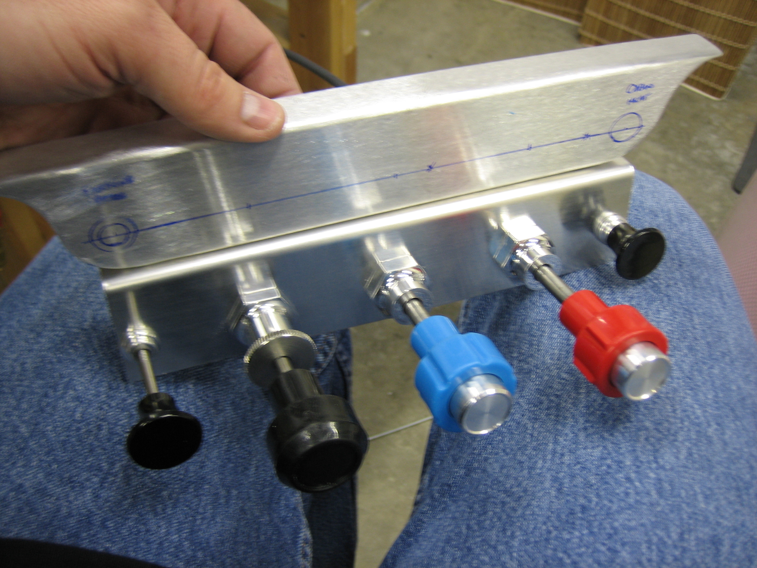
As you can see, I also moved the parking brake knob over to the right side of the bracket so that it’s out of the way. This also has the advantage of bringing the engine controls closer to me. The three engine controls are spaced 3″ apart and the parking brake knob is a hair over 2 1/2″ from the mixture knob. You can also see that I drilled the holes lower than the center of the bracket. They’re 3/4″ up from the bottom edge which leaves plenty of room to provide labels for each of the controls.
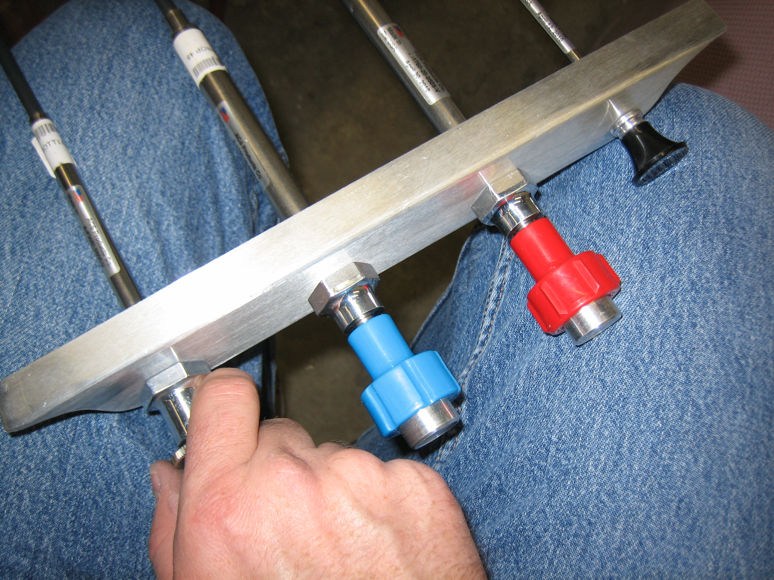
A top view shows that my hand has plenty of room when operating each knob.
I only had a little time in the garage tonight, so I decided to drill the canopy side skirts, mostly to get them off my bench.
Here you can see that the front joint is aligned with the downward bend in the longerons. Since the canopy rails aren’t yet riveted down, there is a gap here that I’m hoping will go away once everything is riveted together.
Here you can see that I left the side skirts a little long so that they can be trimmed to perfectly align with the skin that surrounds the rear window.
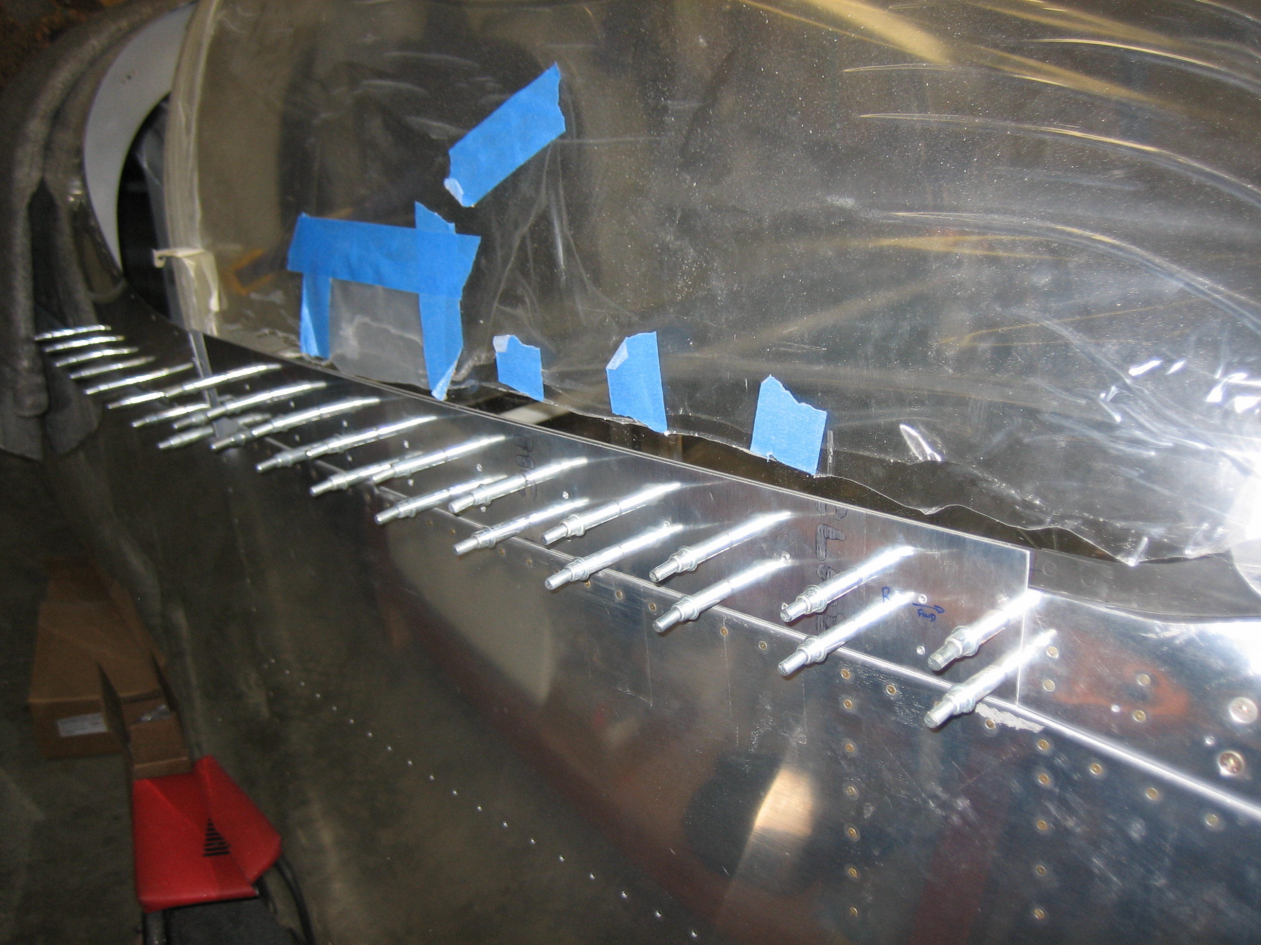
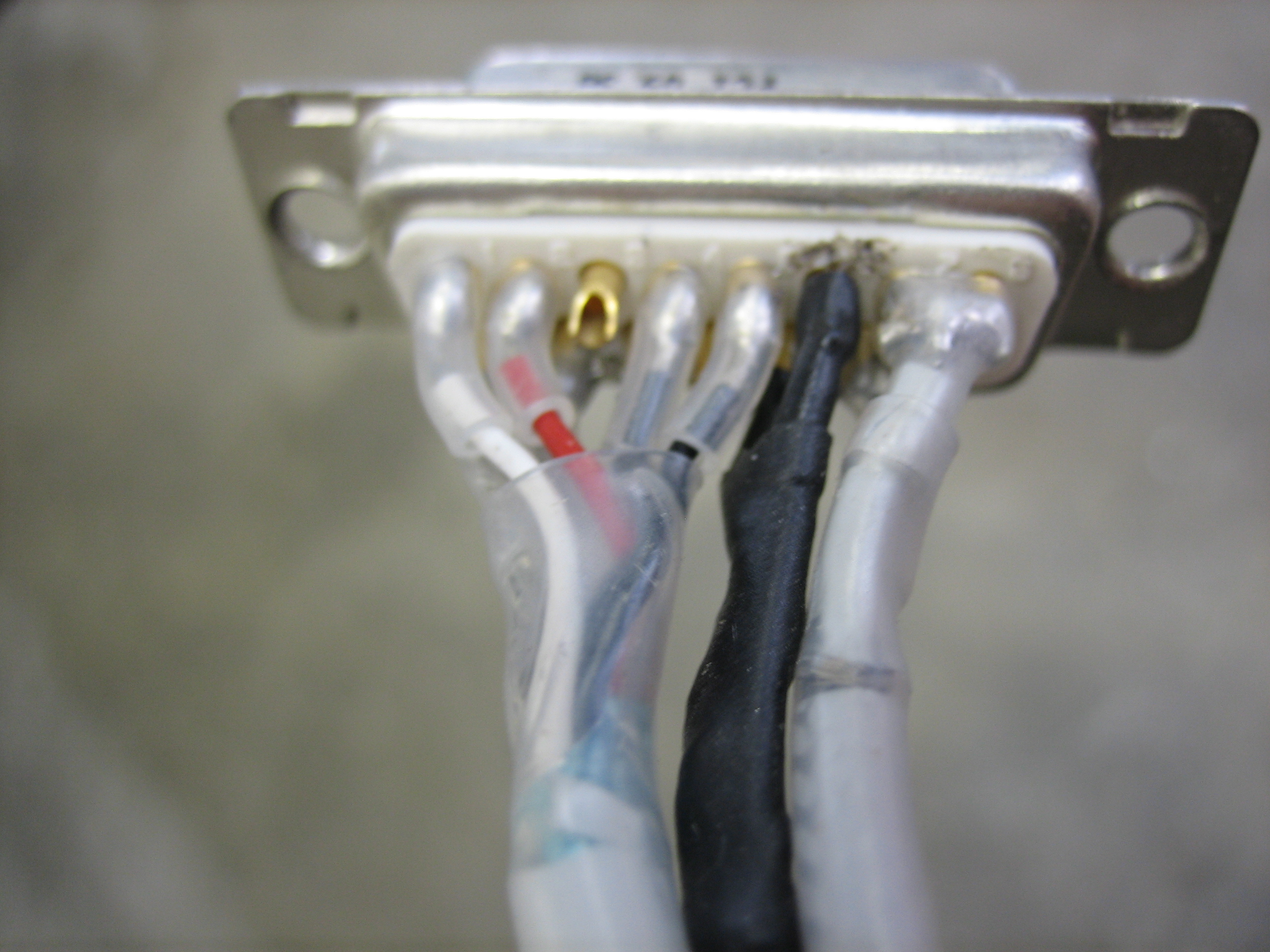
I got an order from Aircraft Spruce today with some shielded 22AWG wire. I soldered the inner wire to pin 6 of the lightspeed input connector and the shield to pin 13. I then slipped inner and outer pieces of heat shrink over the wires and shrunk everything in place.
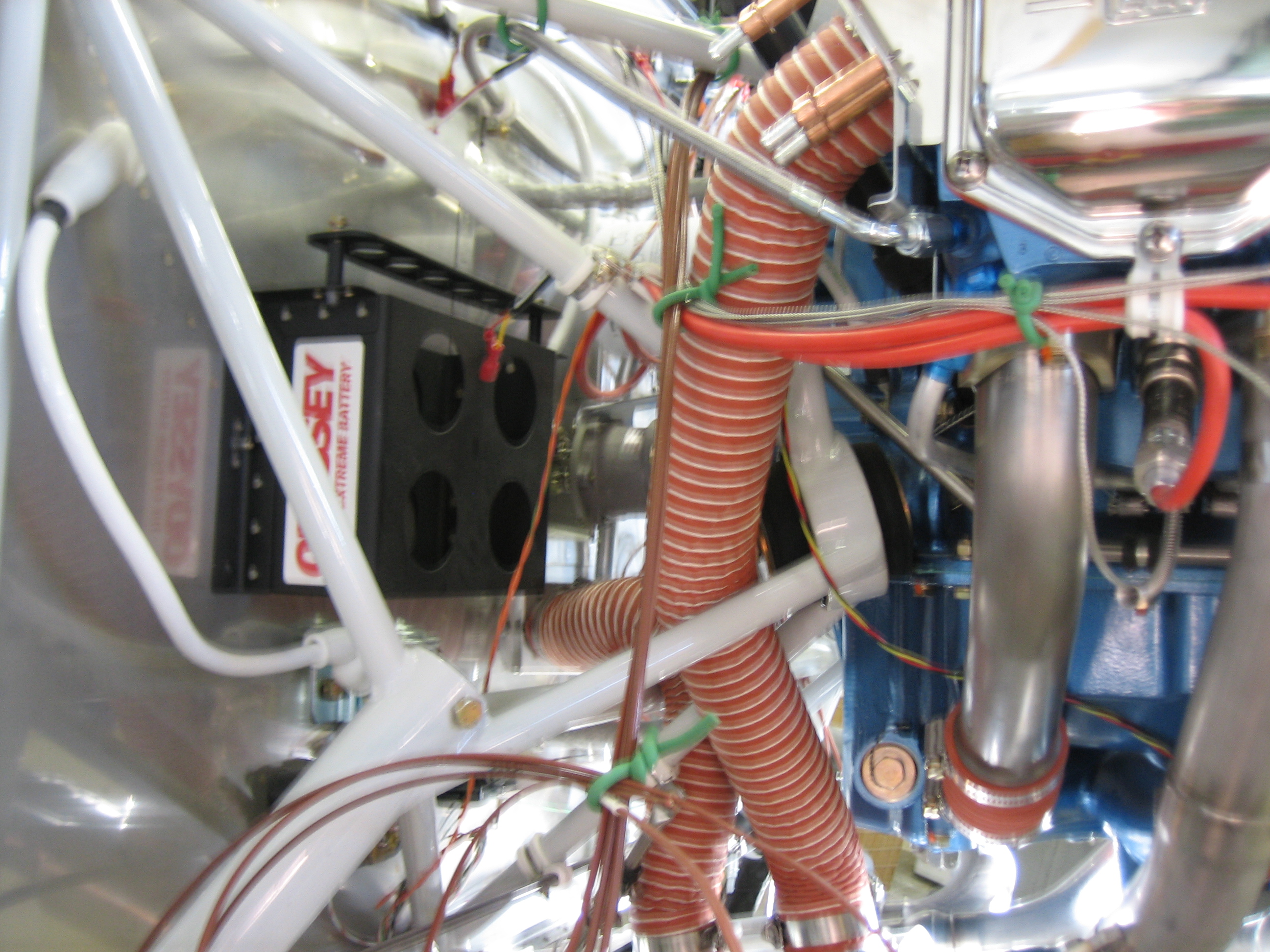
Also in the order was some 2″ scat tube and some 2″ hose clamps. Here is the hose from the output of the heat muff up to the heat box on the firewall.
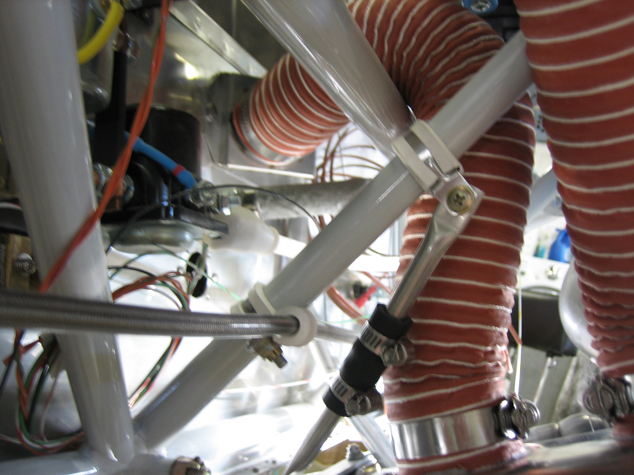
Here is the hose from the back of the baffles down to the heat muff. I’m not sure if I need to secure this at an intermediate point or not; I need to do a little research on that.
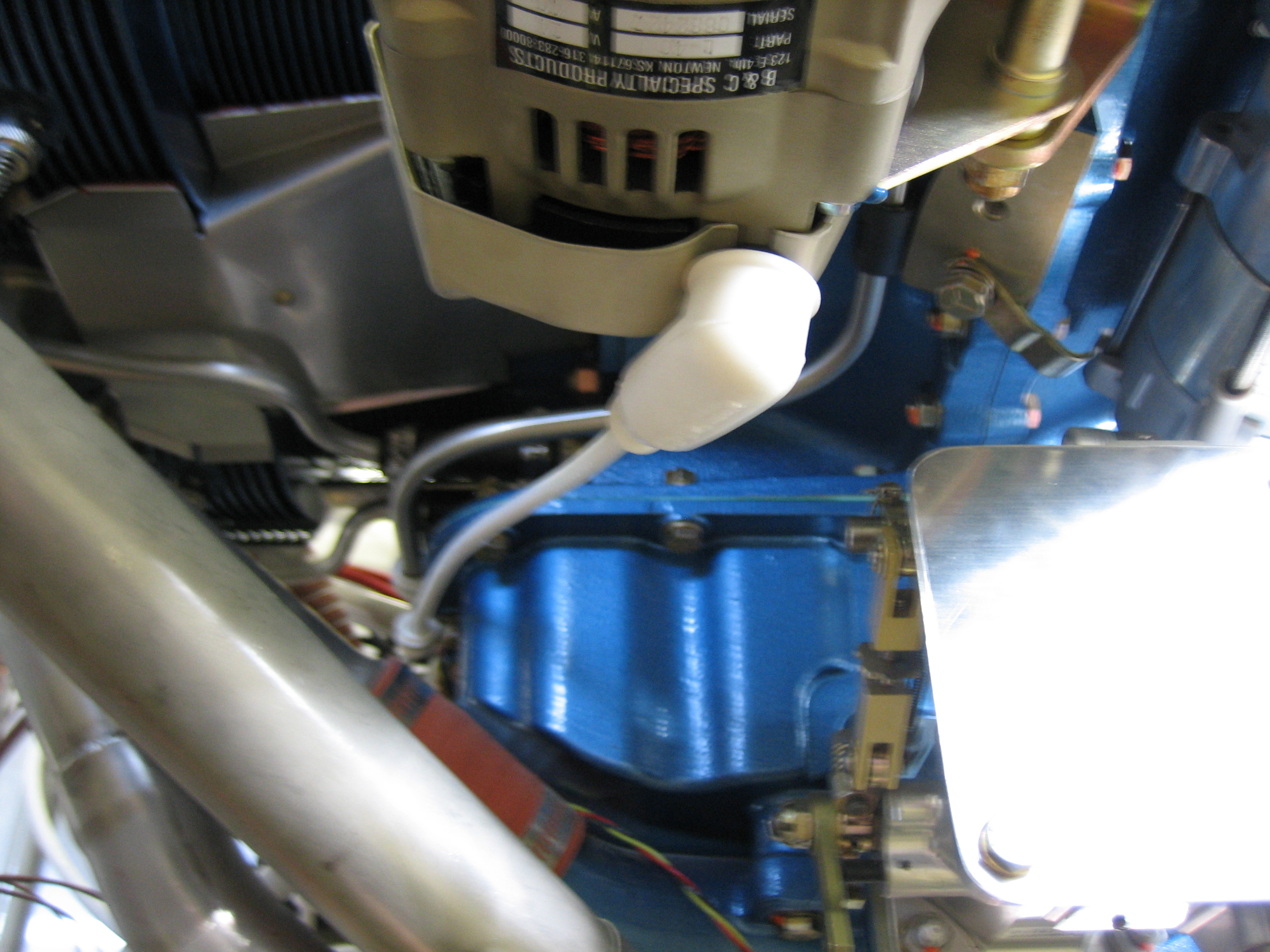
I installed the alternator wire today. This is 6AWG wire which is slightly larger than what is needed for a 40A alternator (8AWG would be fine), but there’s a possibility I may swap this out for a 60A alternator at some point, so I went ahead and ran 6AWG. Here’s the connection at the alternator end. A terminal has been crimped on, then heat shrink over that to act as a strain relief, then a boot over that to keep the hot lead protected.
I anchored the wire to one of the sump bolts where there was already a longer bolt for the prop line.
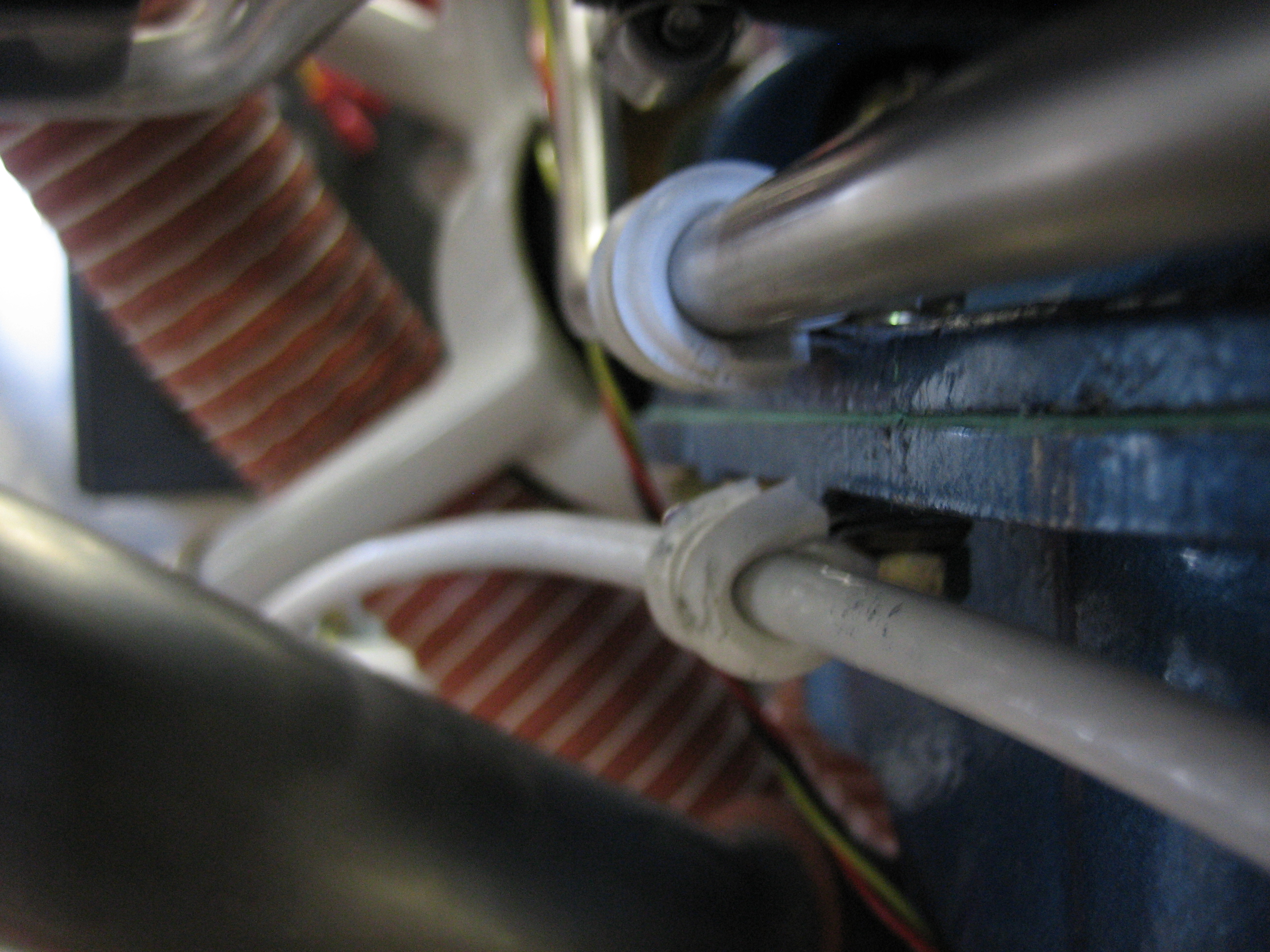
Here you can see that the line is anchored in two more places before connecting to the shunt.
After finishing up the alternator cable, I resumed work on the canopy side skirts. I pulled the canopy and frame off of the plane and drilled the #27 holes for the #6 screws, then deburred, dimpled, and countersunk all the necessary holes.
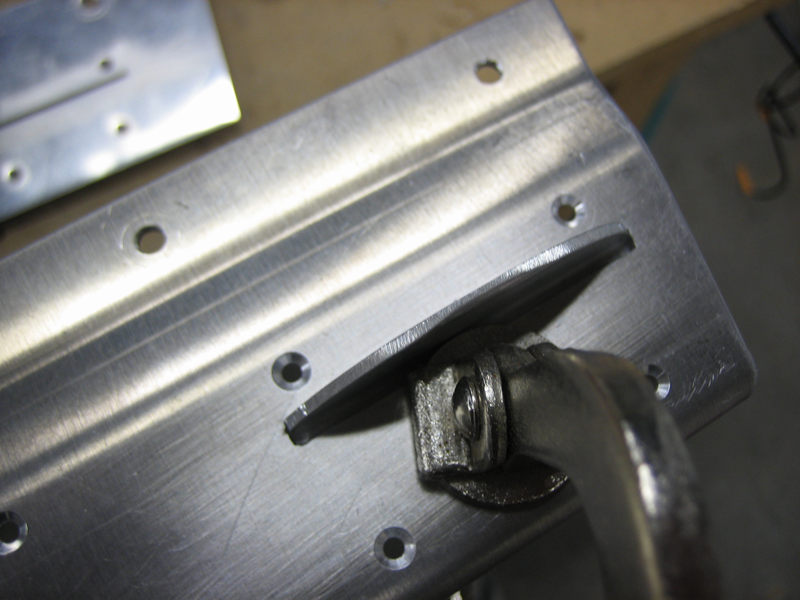
The plans have you fabricate a boring, angular canopy lift handle and then rivet it to the outside of the canopy frame. I thought it looked cheesy, so I’m deviating a bit here. First up is to round the handle nicely instead of just chopping the corners off.
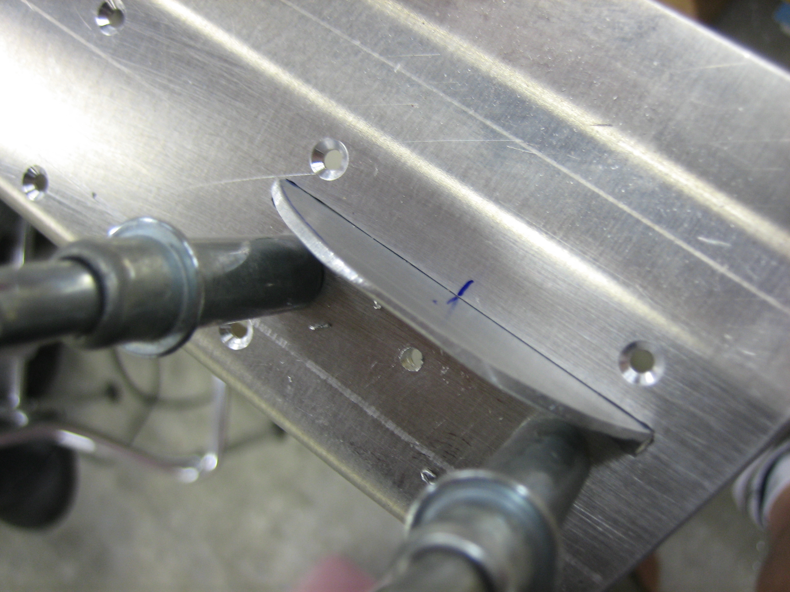
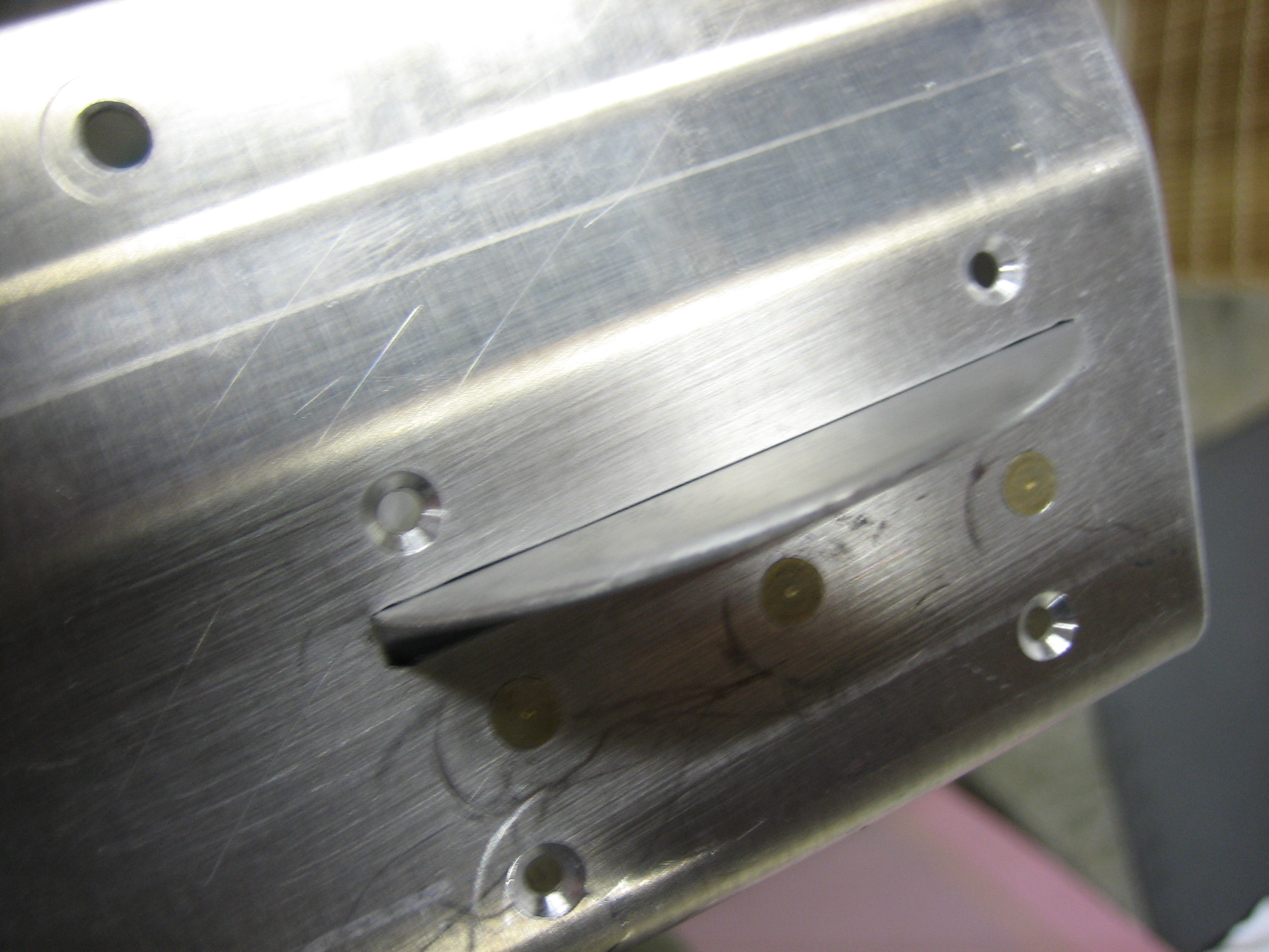
I then cut a slot in the canopy skirt and frame. This will allow me to mount the handle on the inside and only have the horizontal piece be seen from the outside. I made the initial slot with the cutoff wheel in the die grinder and then used needle files to get it perfect.
I then clamped the handle to the inside of the canopy frame only.
And drilled the frame to the handle.
After deburring, countersinking, and priming the mating surfaces, I riveted the handle to the frame only.
Finally, I installed the skirt and riveted it to the frame. This looks so much nicer than the handle specified in the plans and only took about an hour to do. While I was working on the side skirts, I rewatched (mostly just listened to) Evil Dead III: Army of Darkness for about the 20th time. That is such a fucking awesome movie; Bruce Campbell rocks.