Drilled Canopy Frame Hinge Brackets

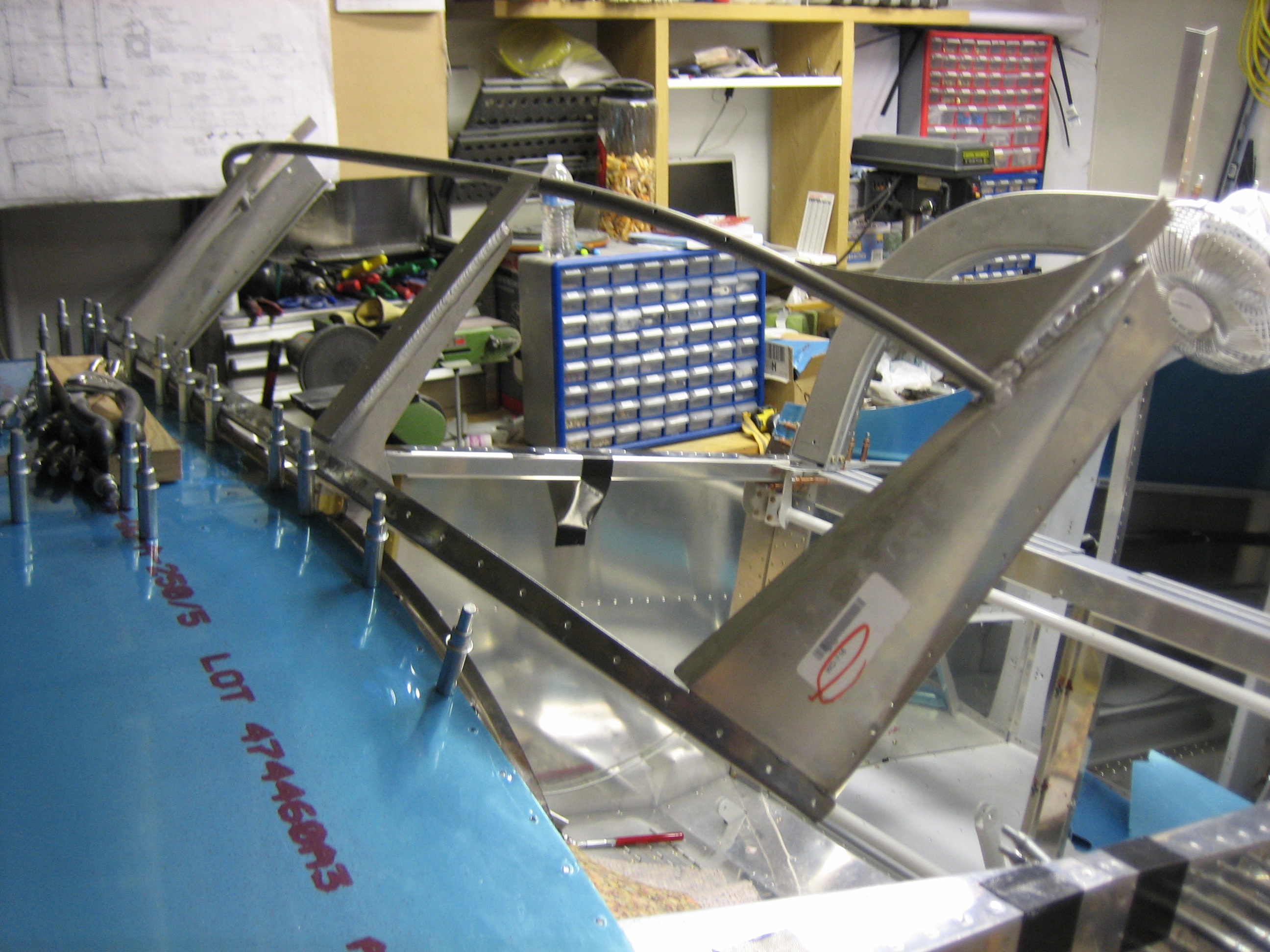
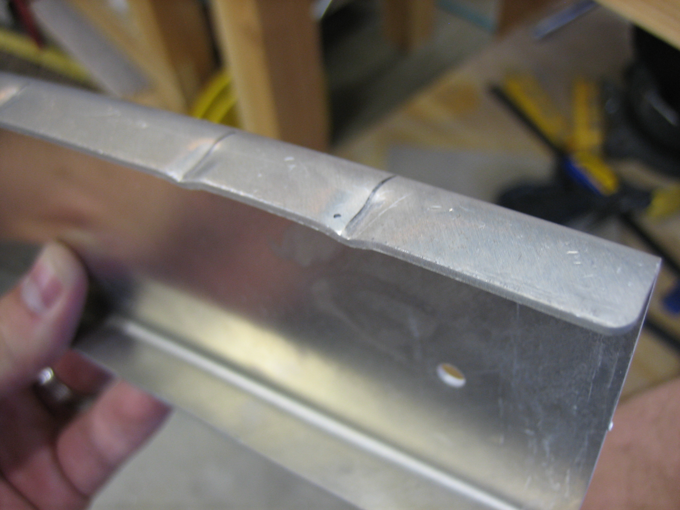
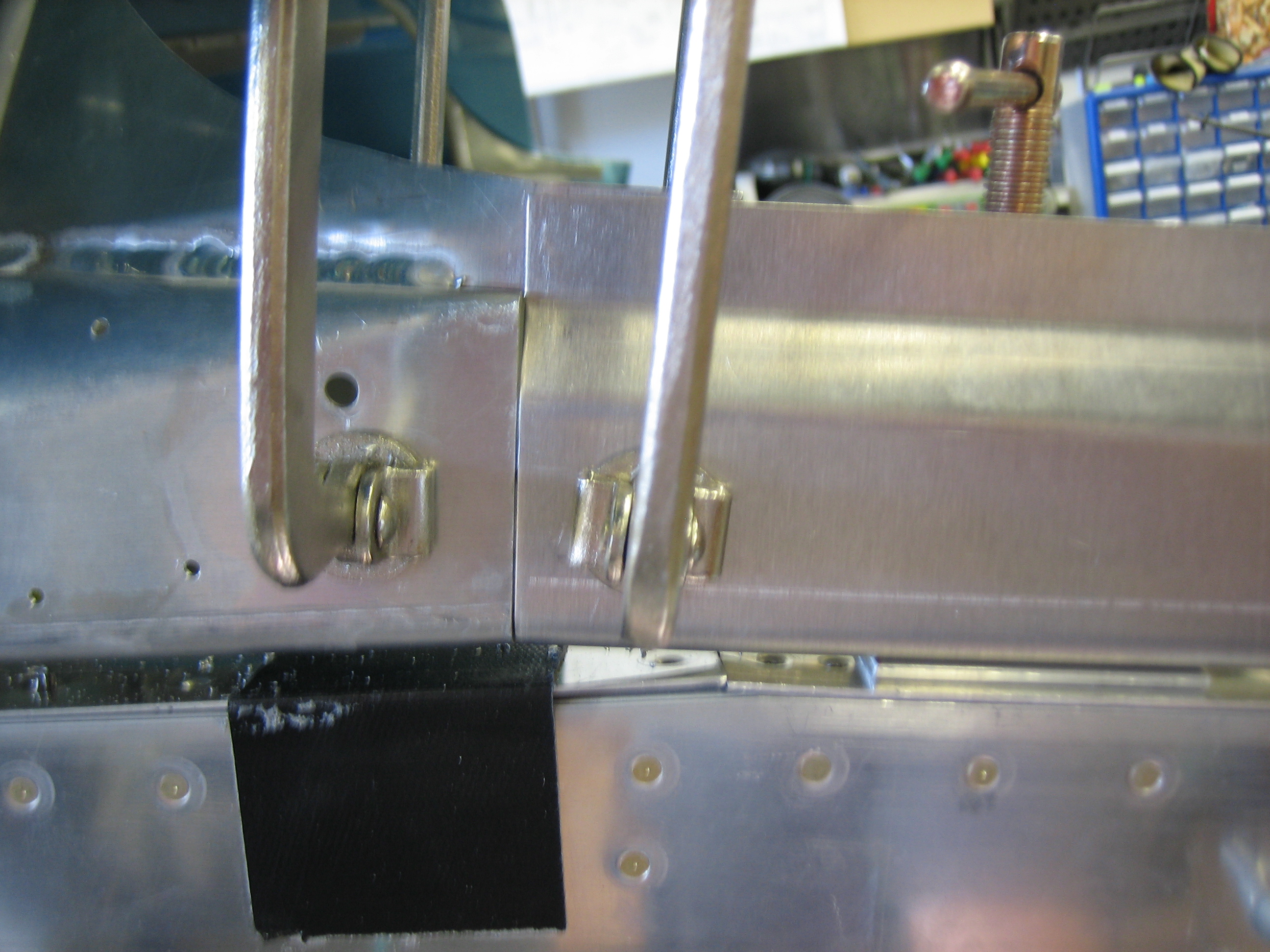
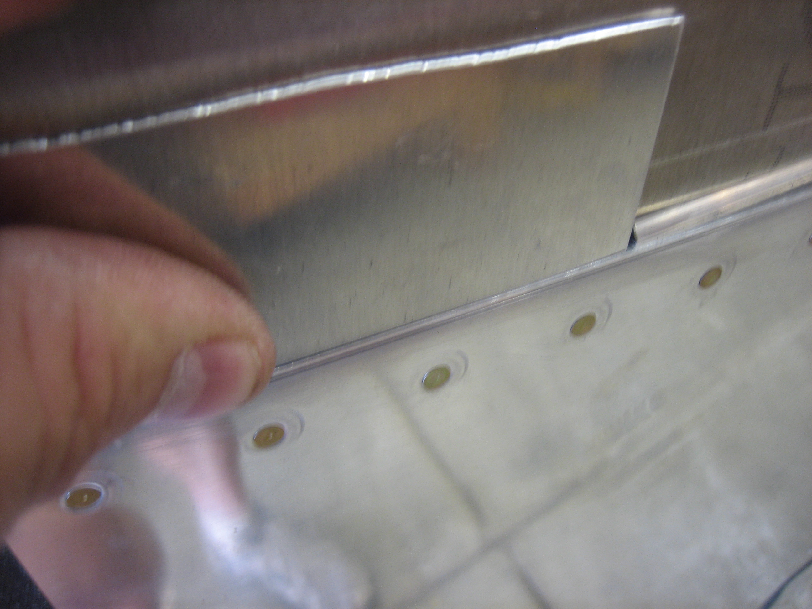
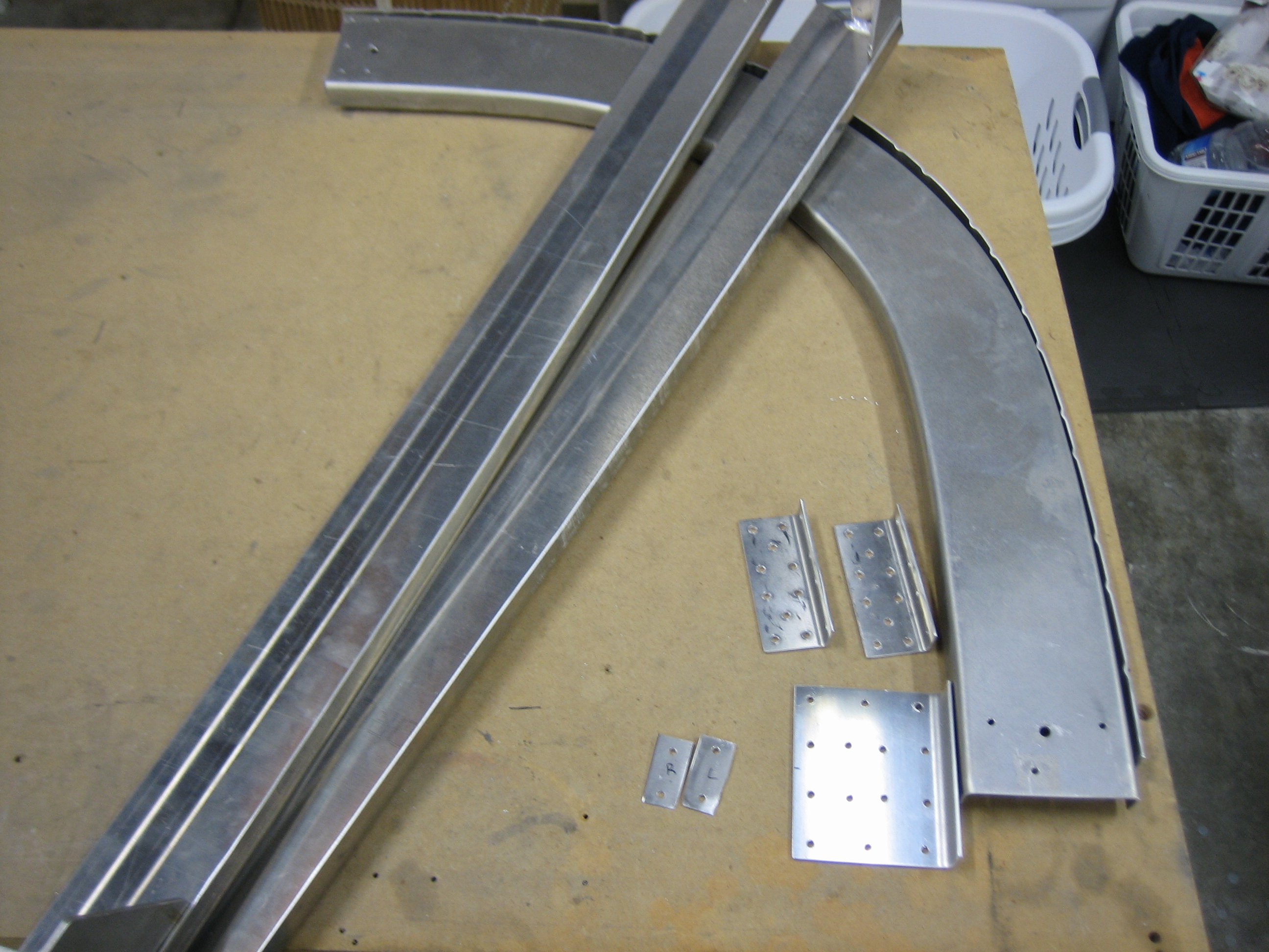
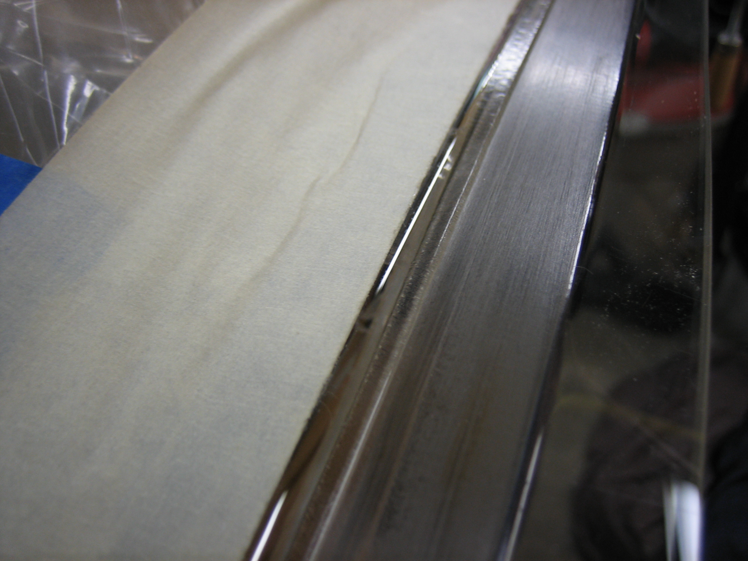
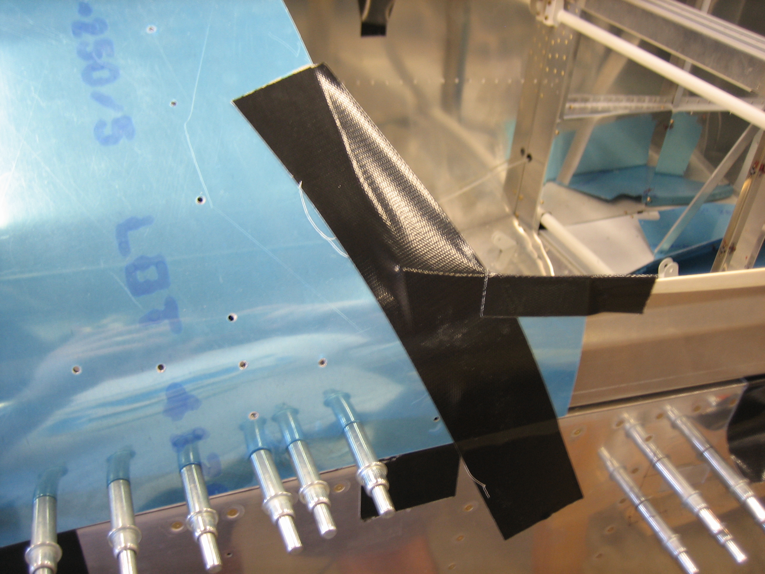
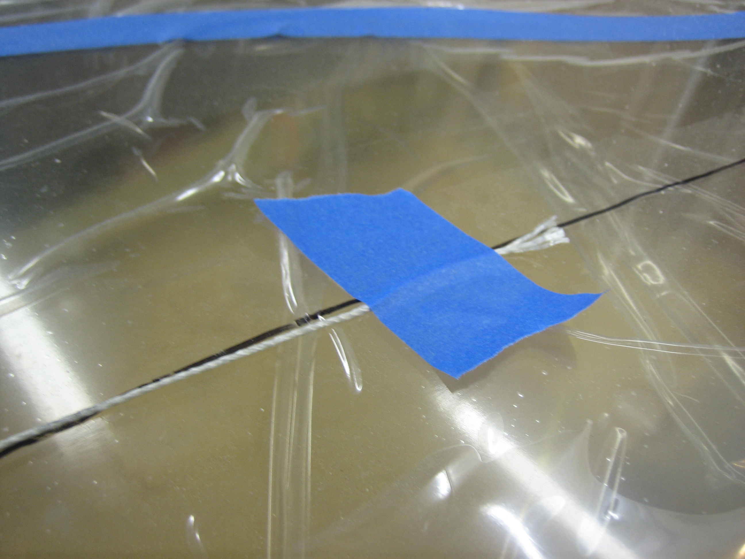
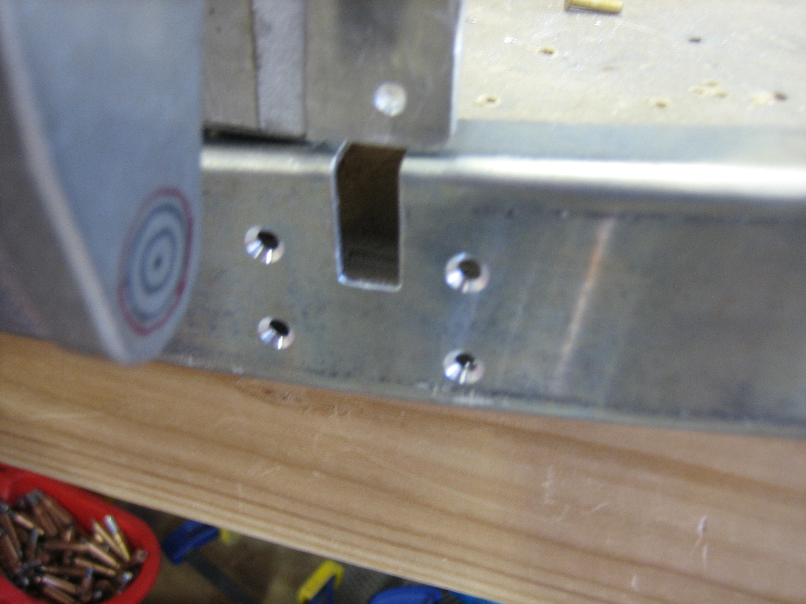
I drilled the channel to the flanges on the hinge bracket.  I then disassembled the frame and deburred everything and countersunk all of the holes on the forward face of the channel.  You can also see the little target I drew on the hinge arms.  Once I get the canopy frame in position, I can look through the holes in the hinge blocks.  As long as I don’t see any of the red line, I will have plenty of edge clearance on the pivot hole.

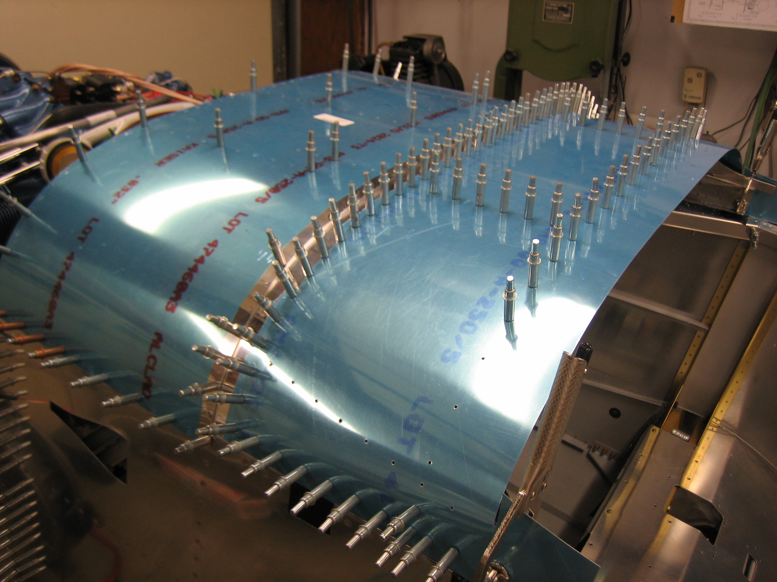
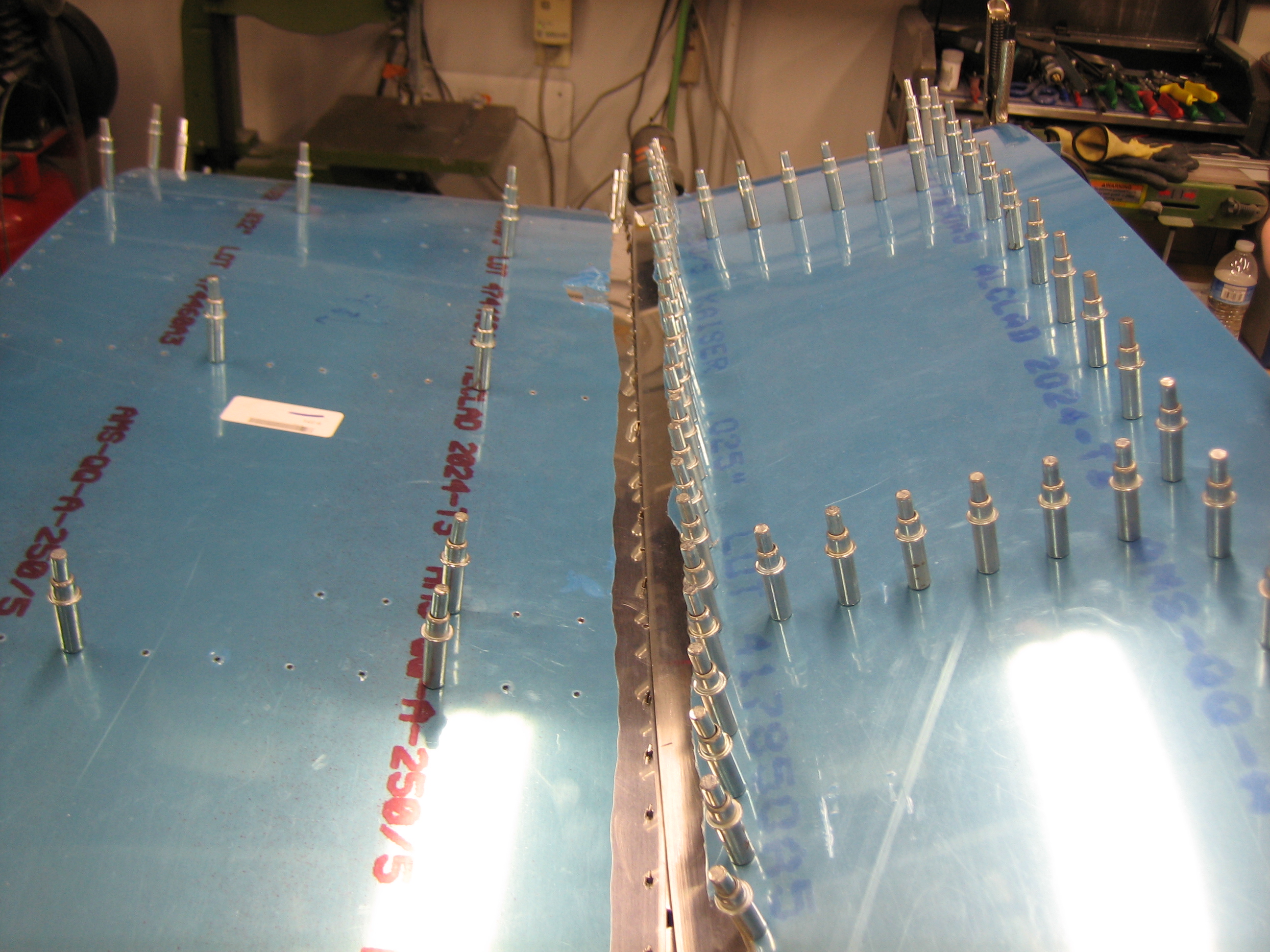
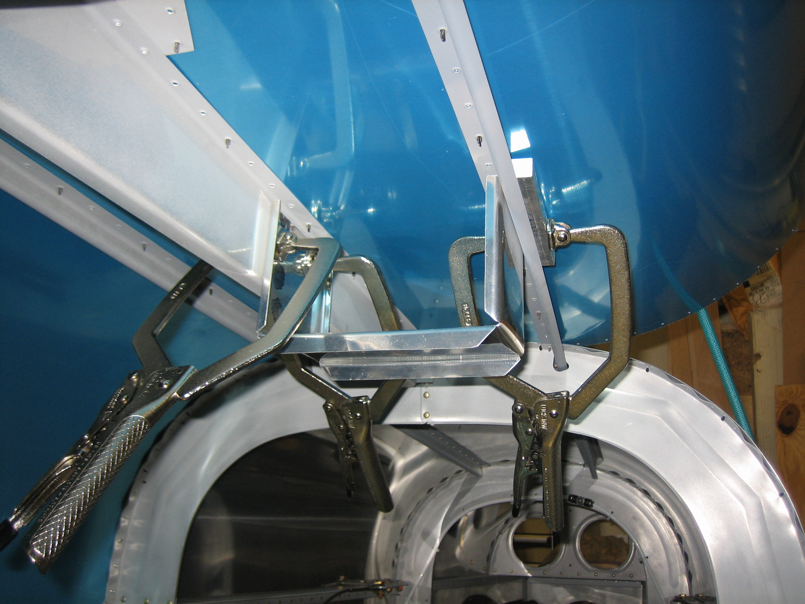
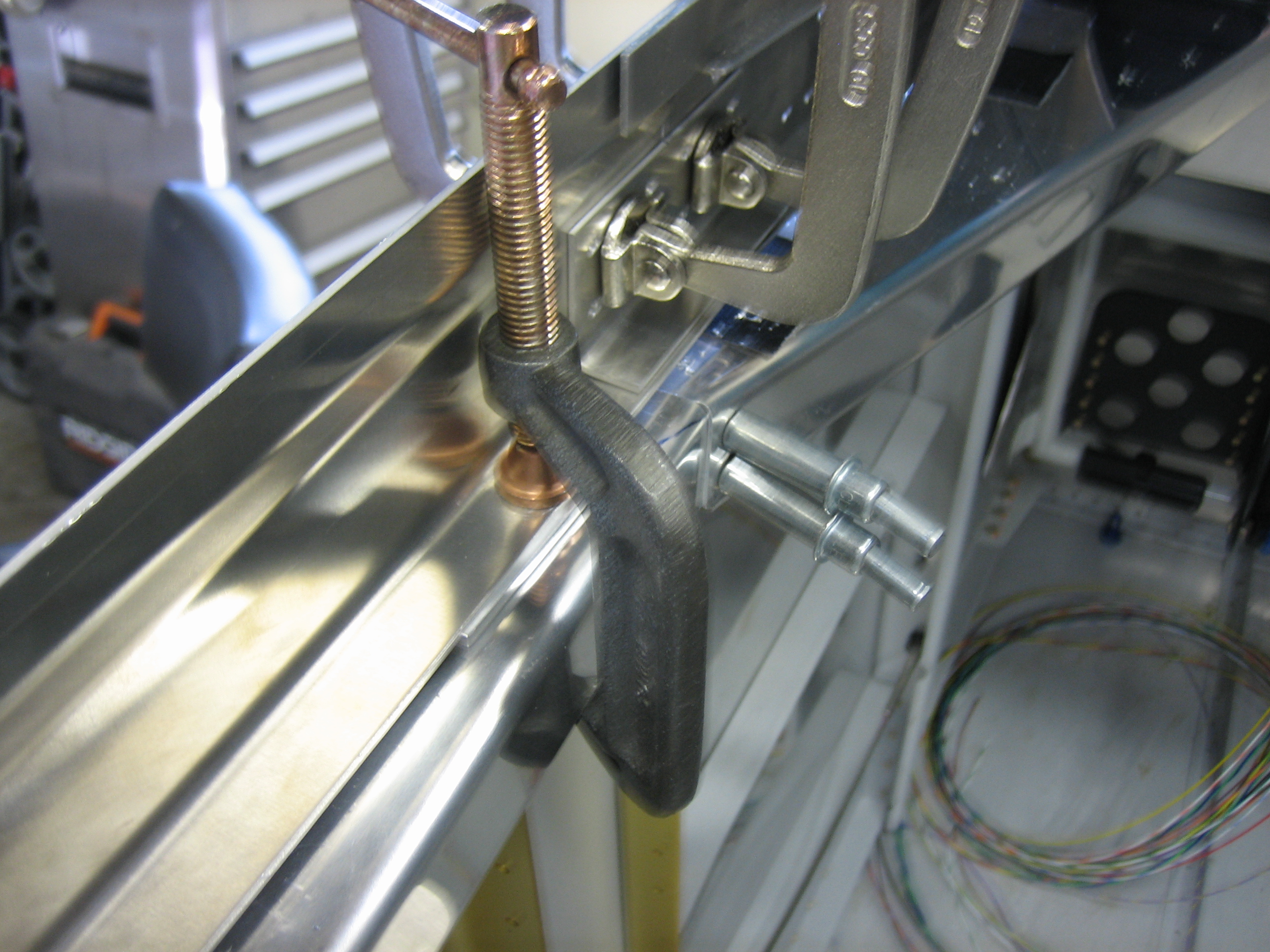
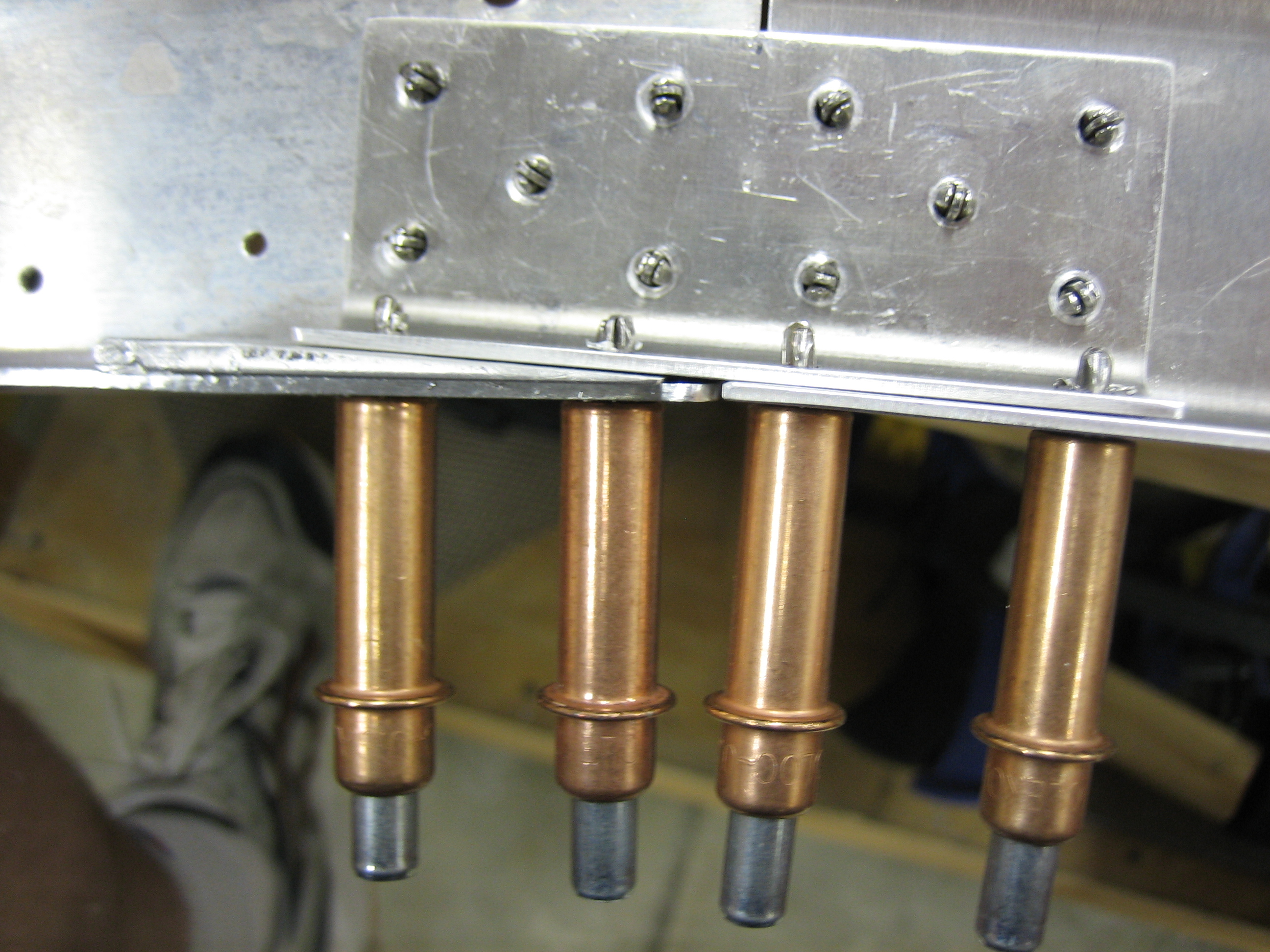
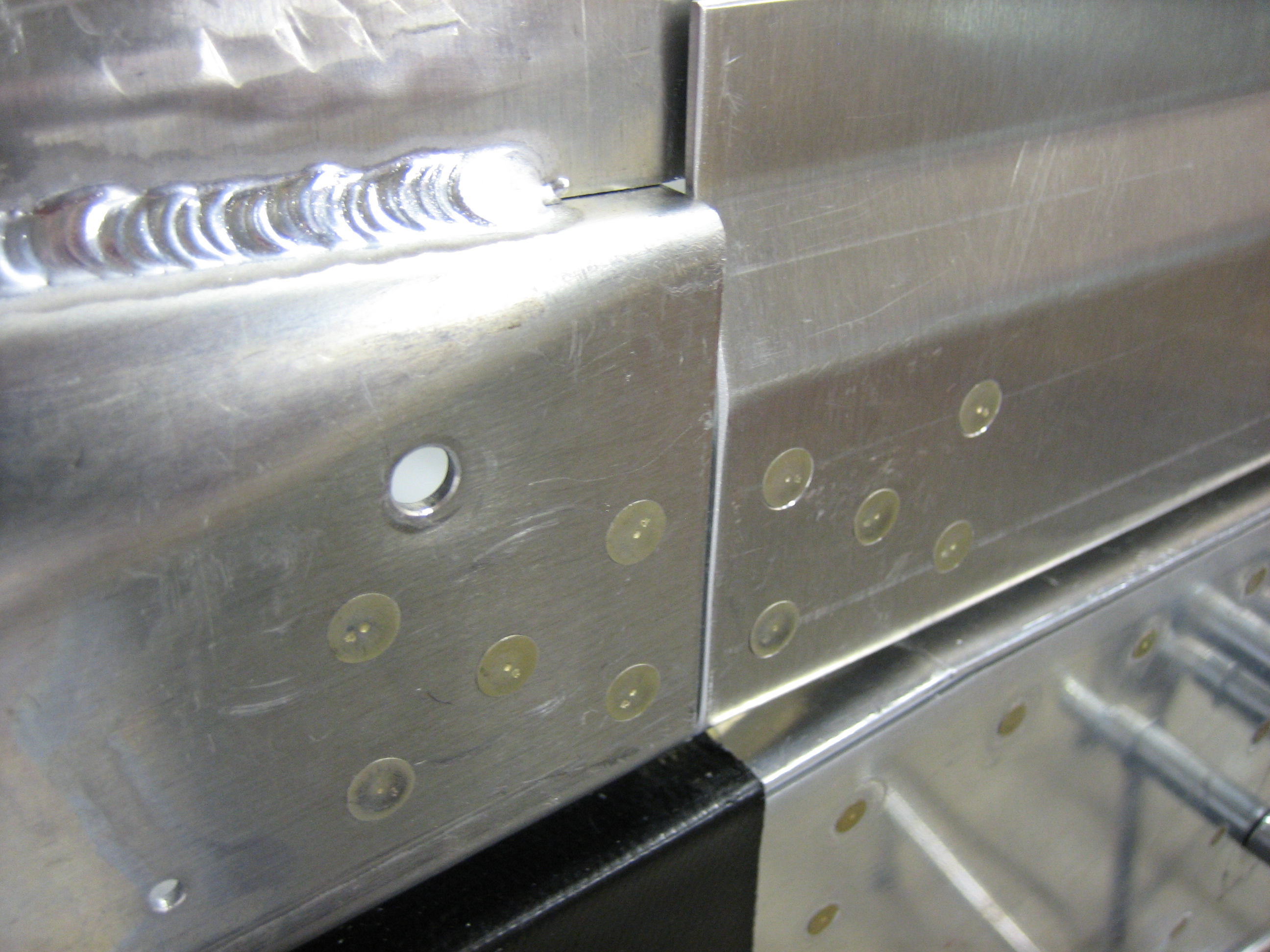
After spot priming all of the mating surfaces, I clamped the frame to pull the sides in as far as possible since the clecoes allow some flex.  I then squeezed all of the rivets in the splice plate.

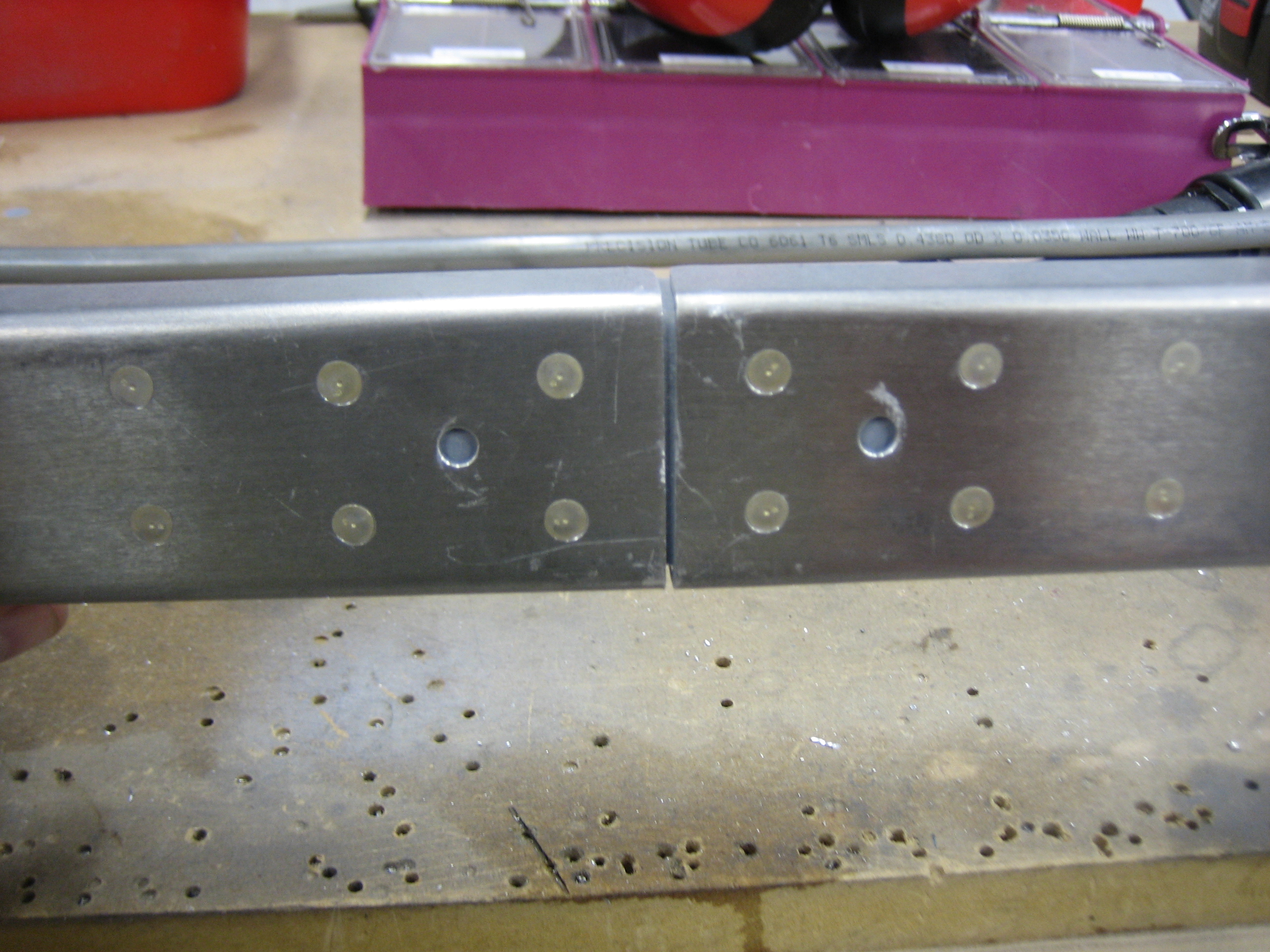
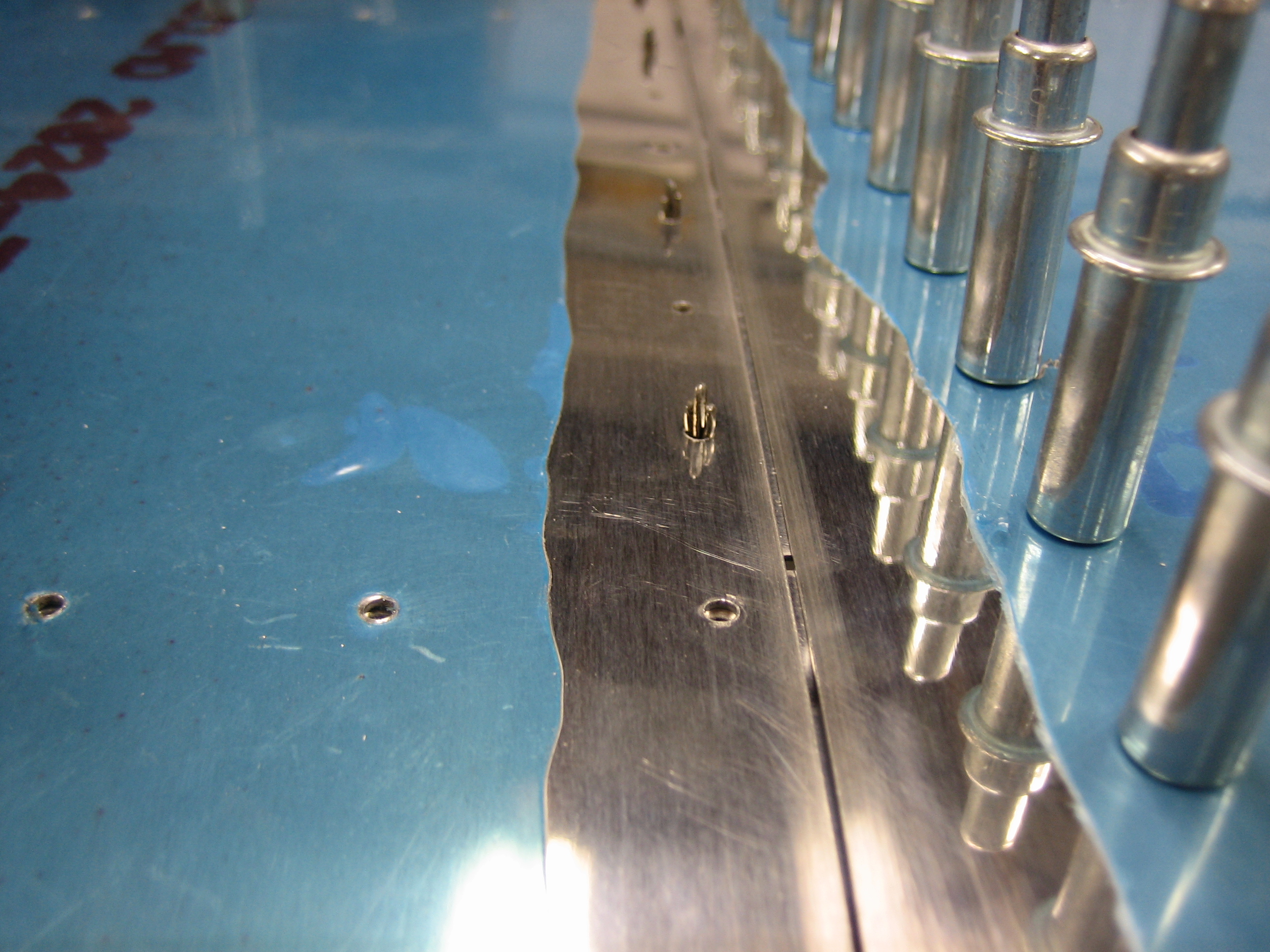
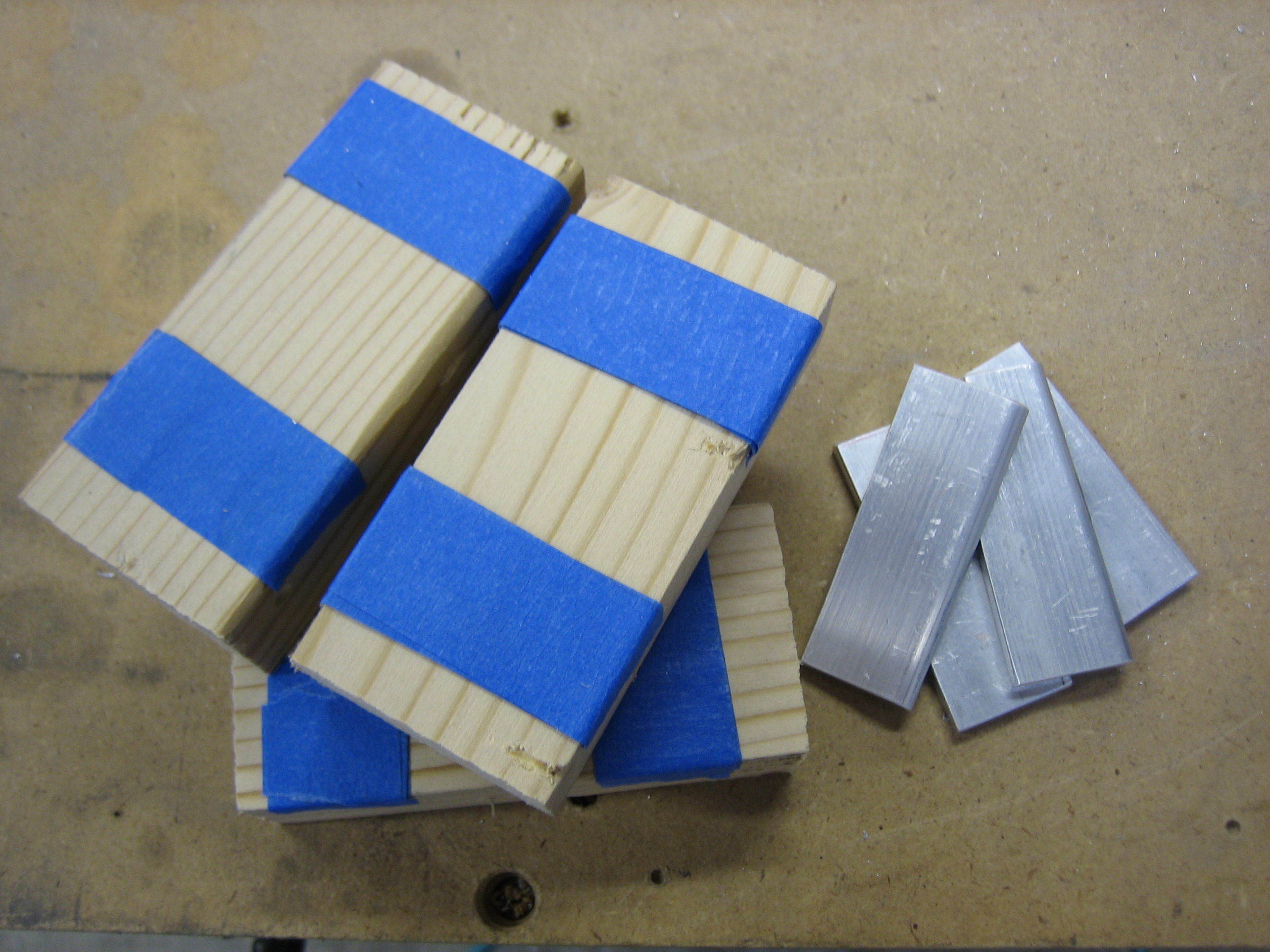
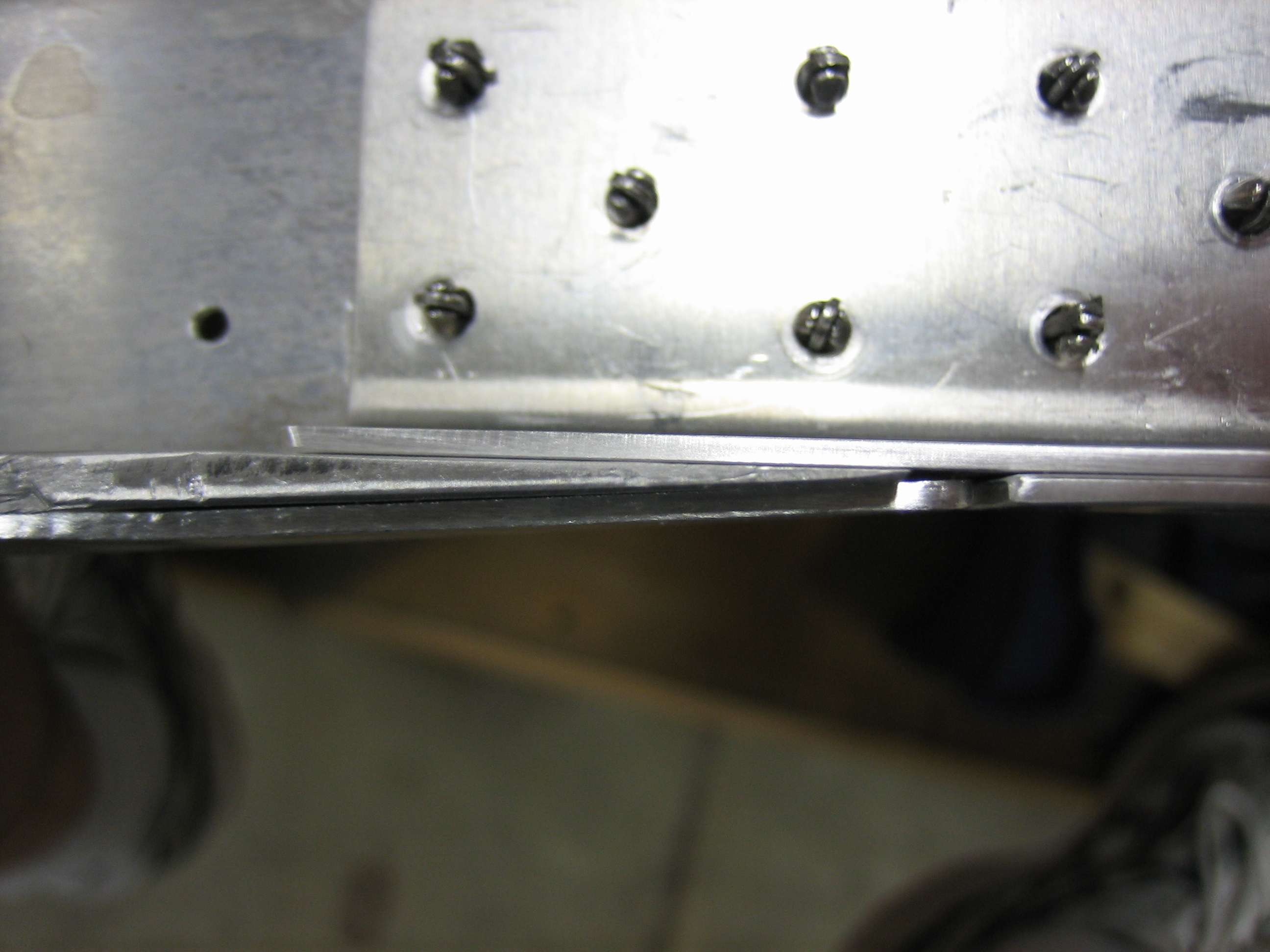
I also squeezed all of the rivets holding the hinge bracket to the channel.  I ended up needing to make some spacers that fit between these two pieces since the hole spacing on the skin pulled the bracket back slightly.

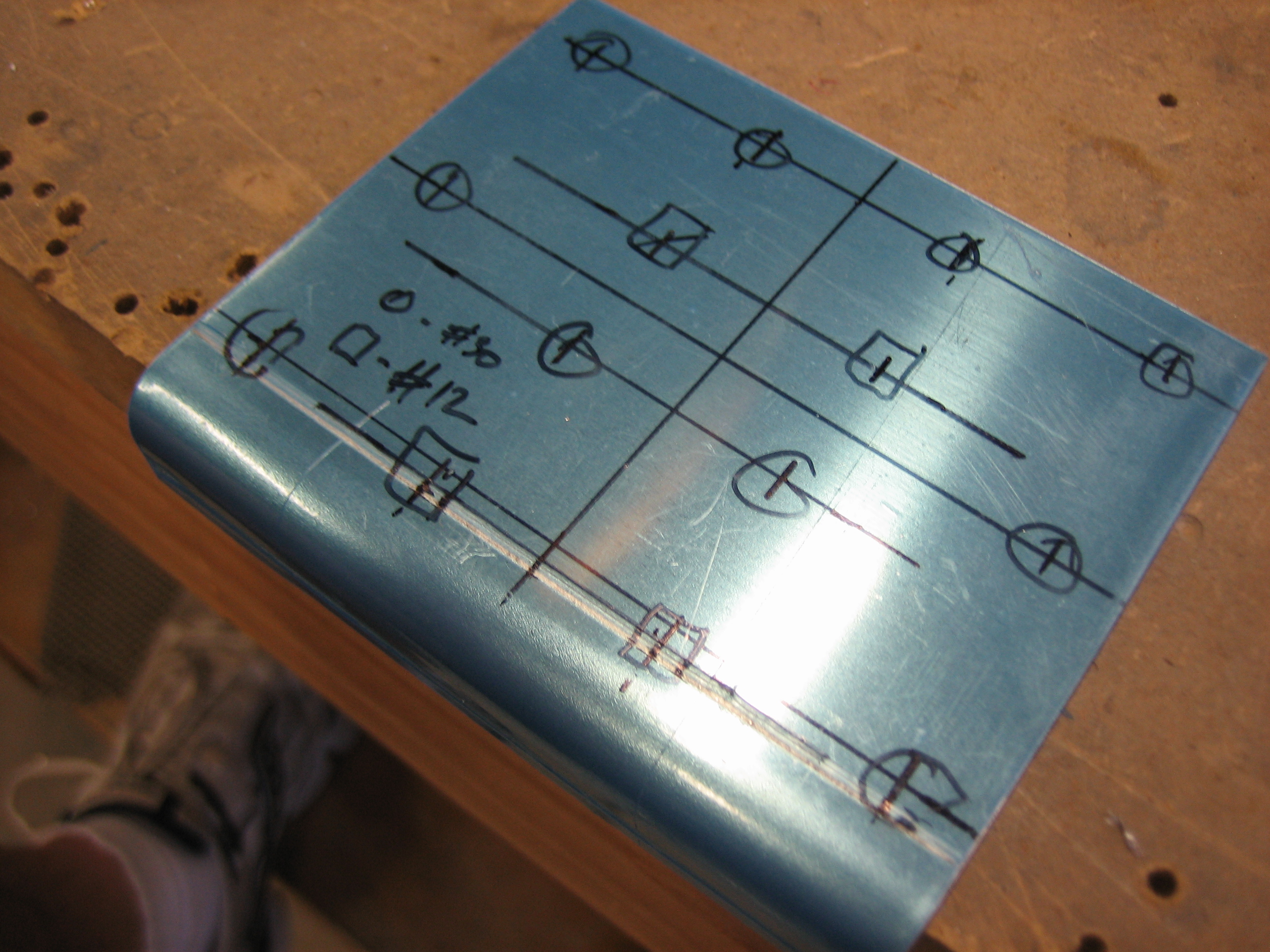
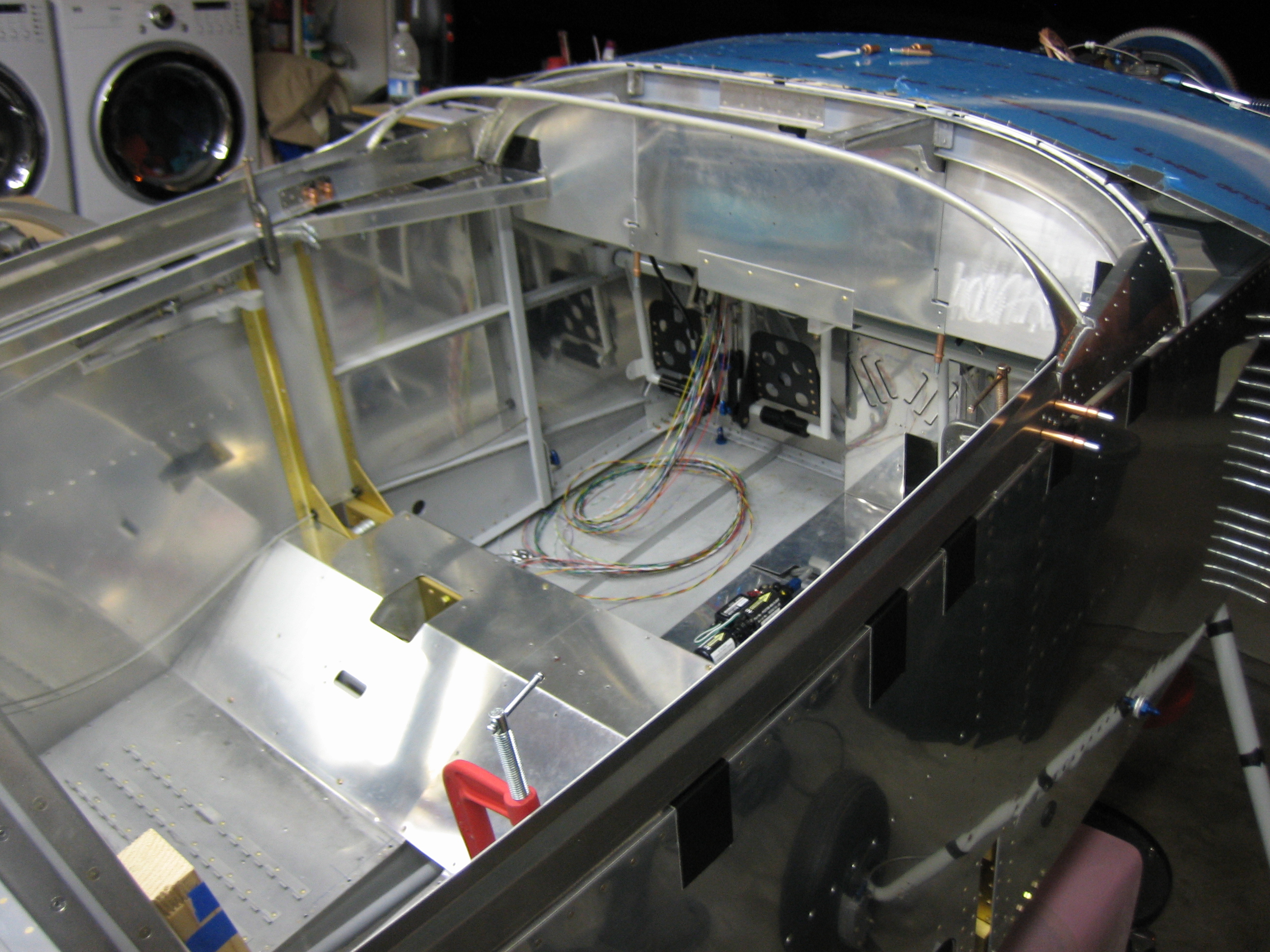
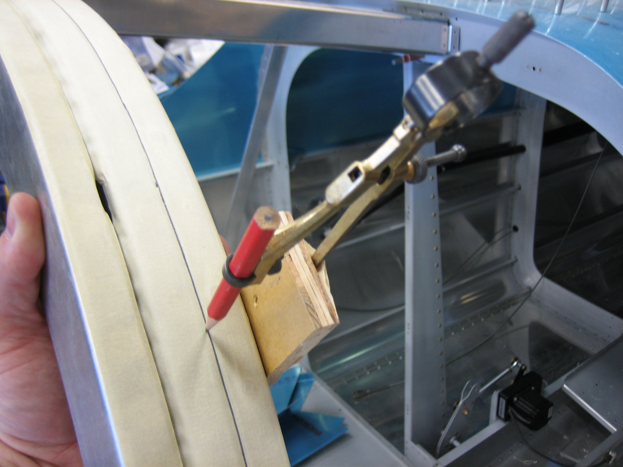
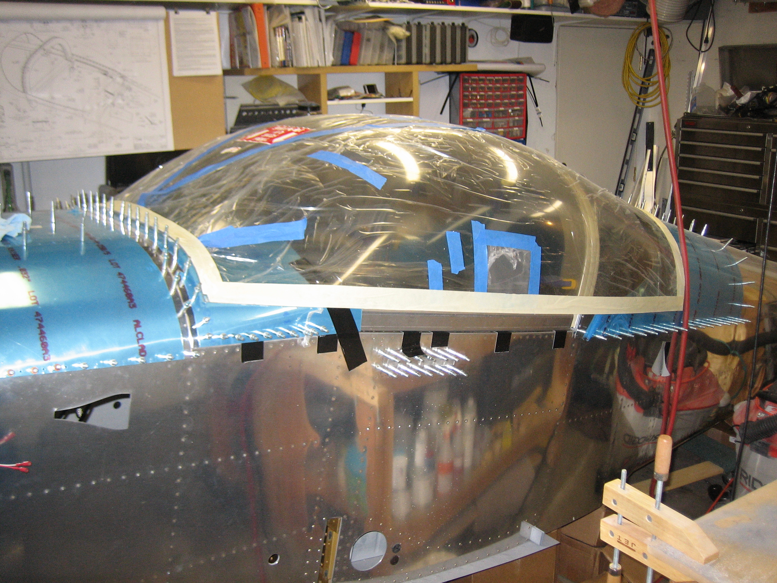
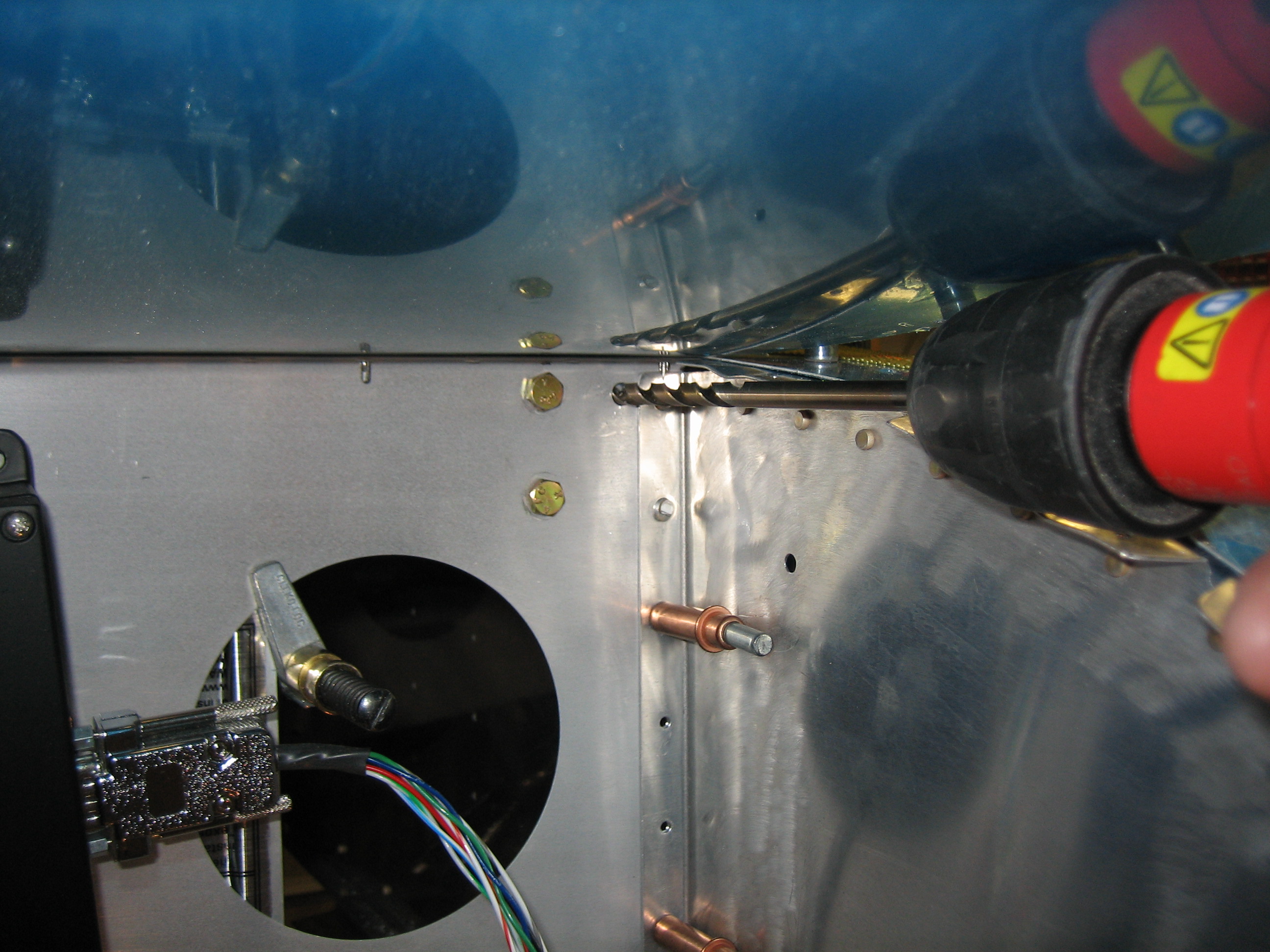
I then reinstalled the canopy frame on the fuselage and got it back into position.  I crawled in the fuselage to confirm the holes would land in the right spot and they were great.  Plenty of edge clearance all around.  I tried using my right angle drill, but I couldn’t get squarely on the hole.  Instead, I decided to peel up the outboard portions of the forward skin and use a straight drill.  If you click on the picture to zoom in, you can see that the hole is nearly centered on my target.

I used my straight drill with a 6″ long, 1/4″ bit to mark the holes.

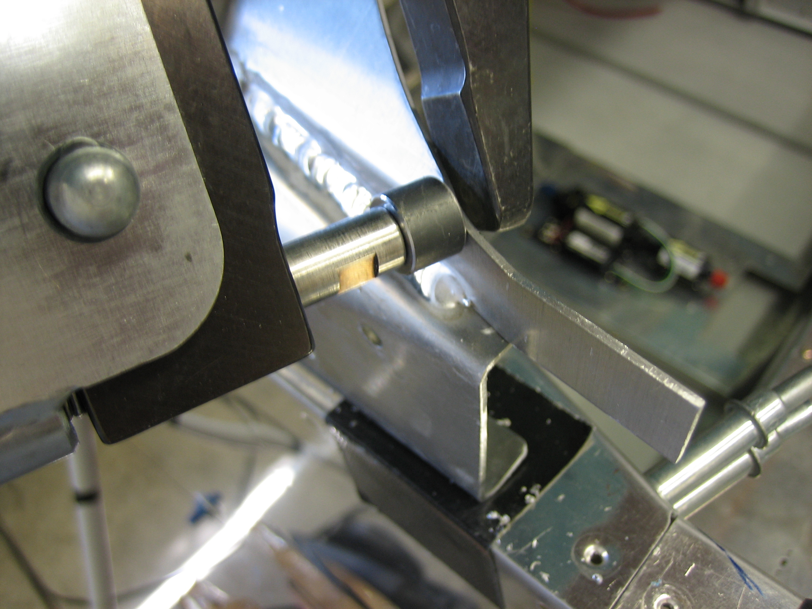
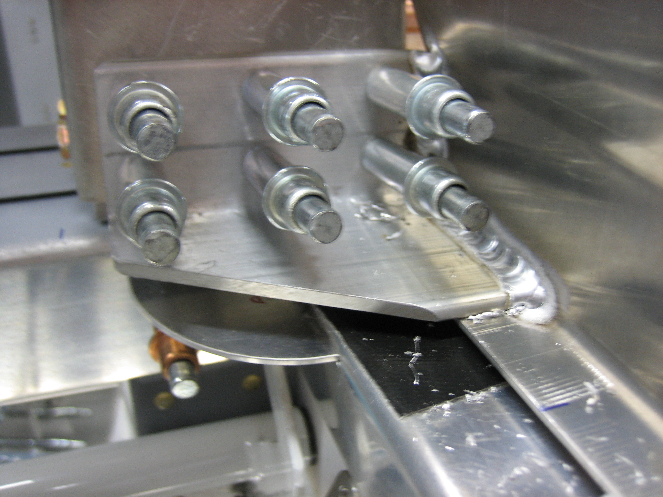
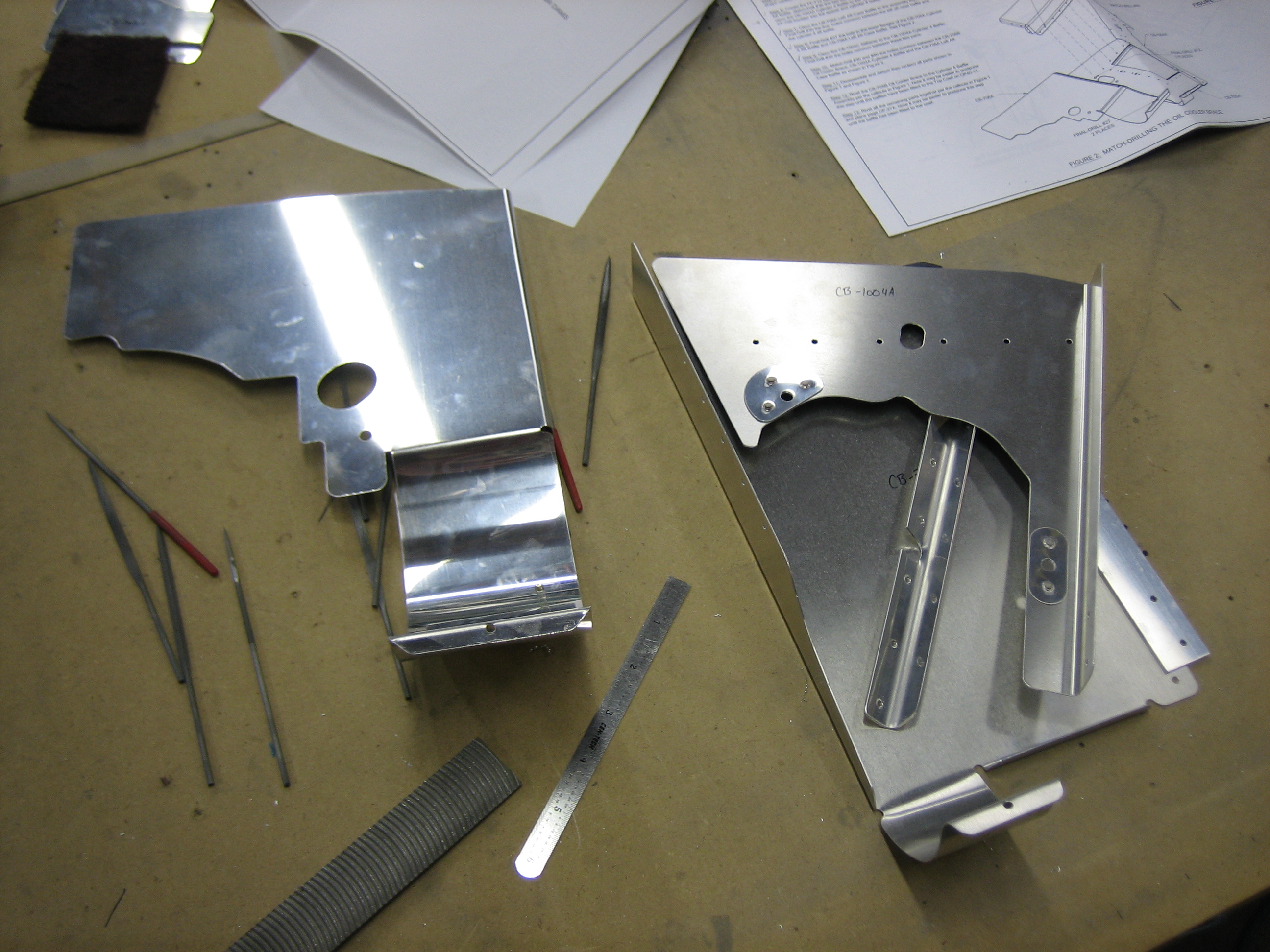
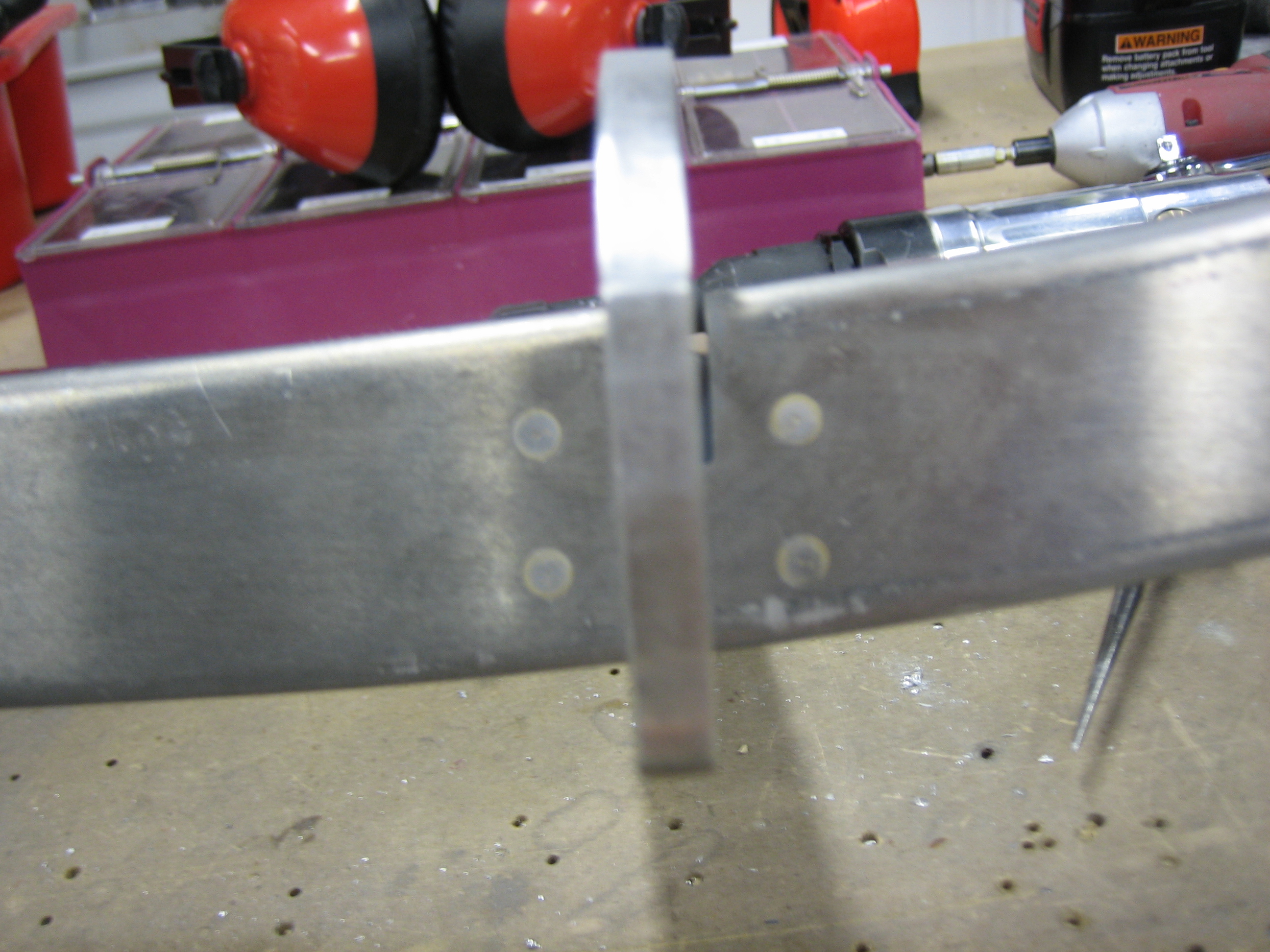
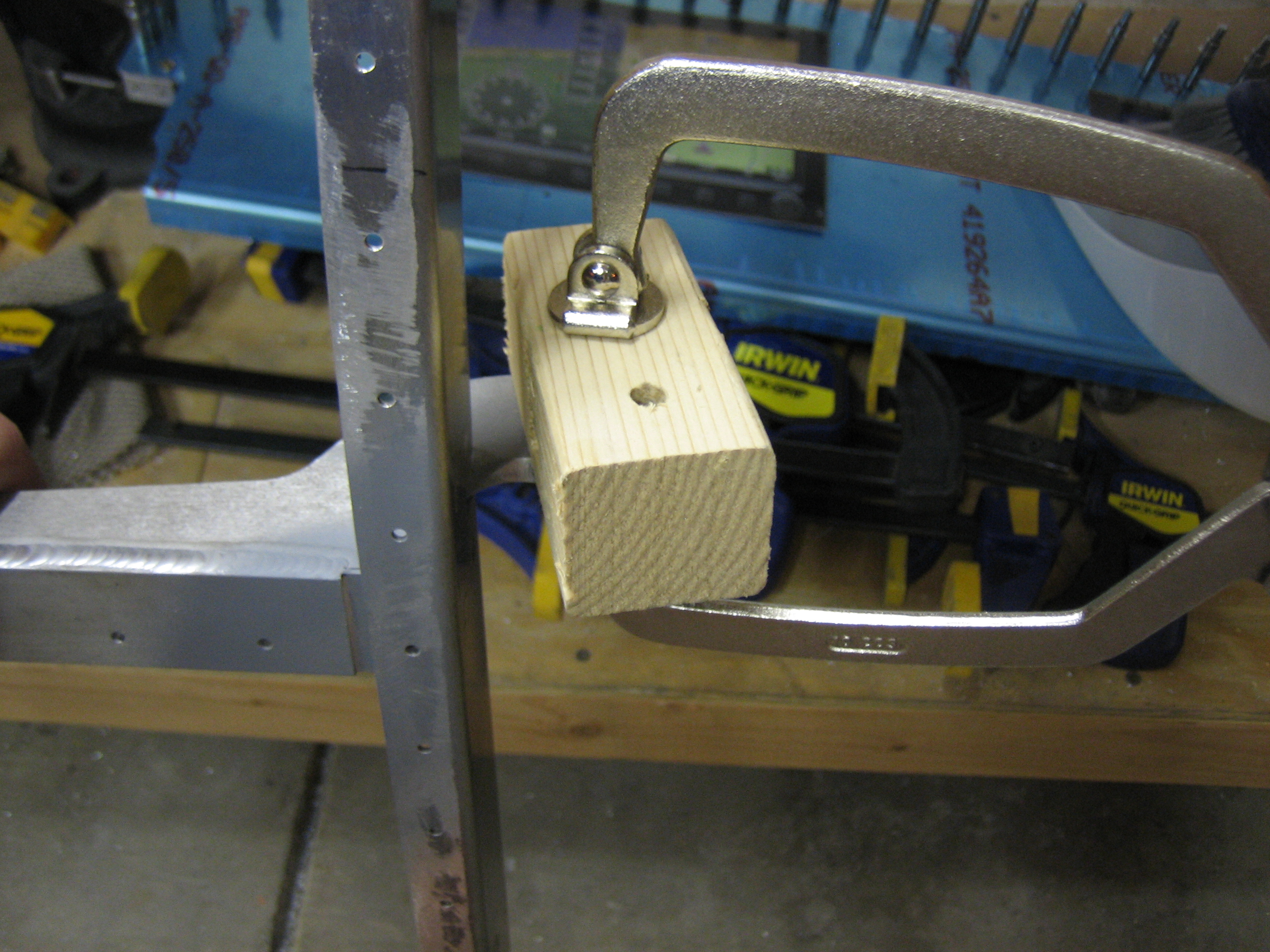
Then a fabbed up a little drilling block to ensure the hole would be square and drilled all the way through the brackets with the 1/4″ bit.

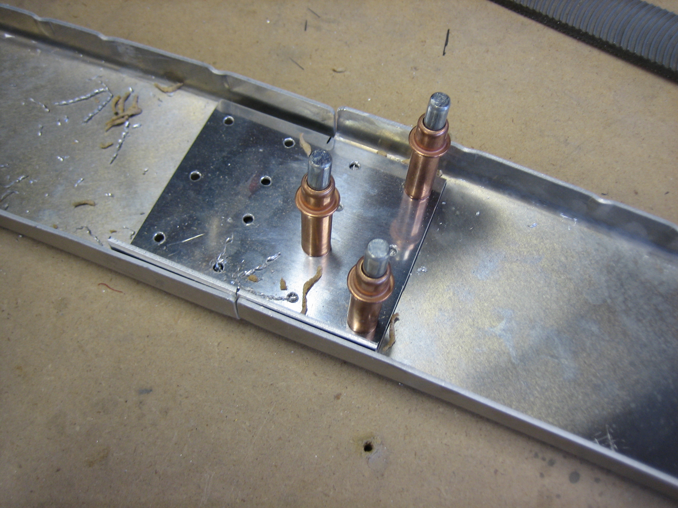
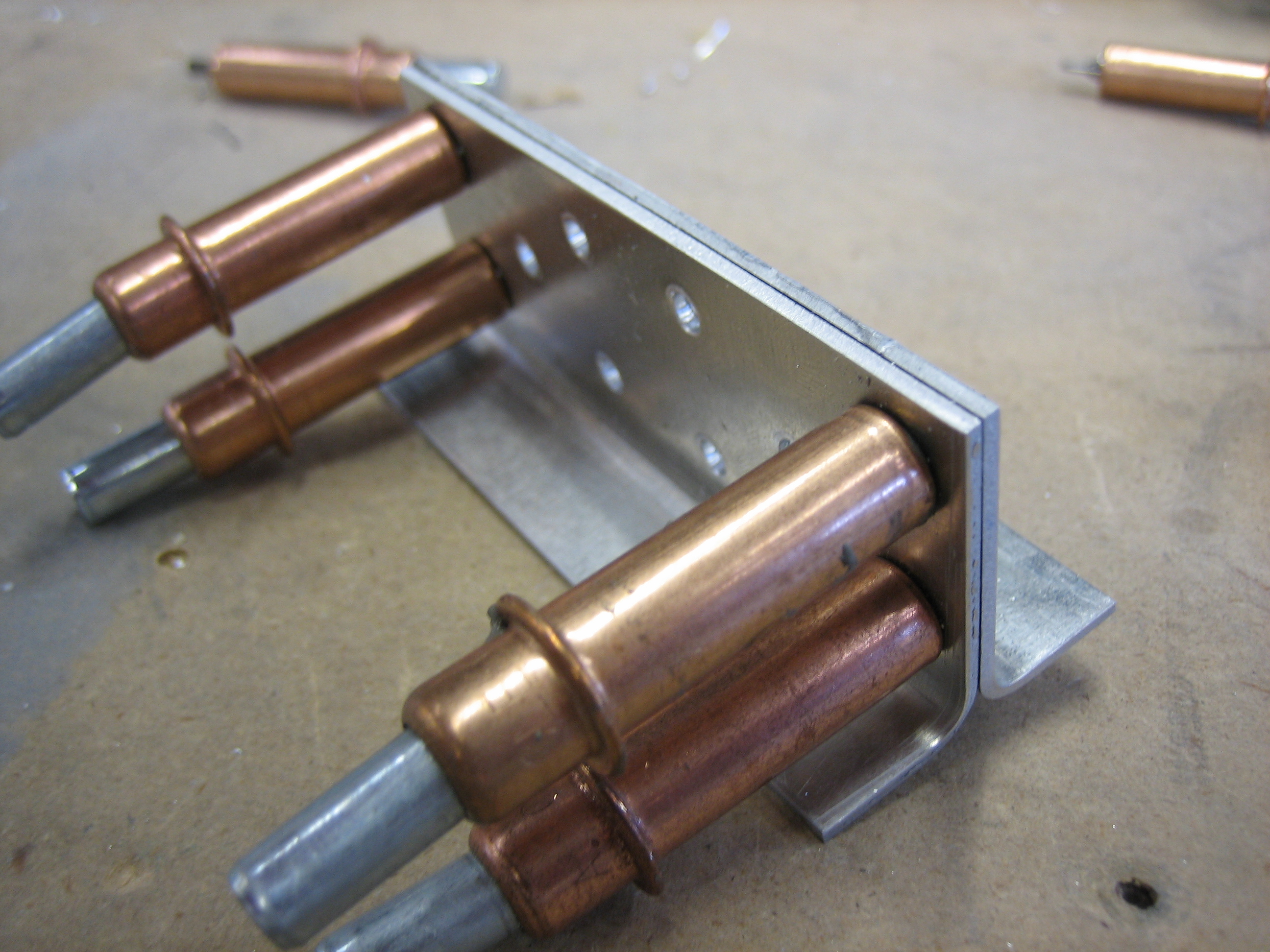
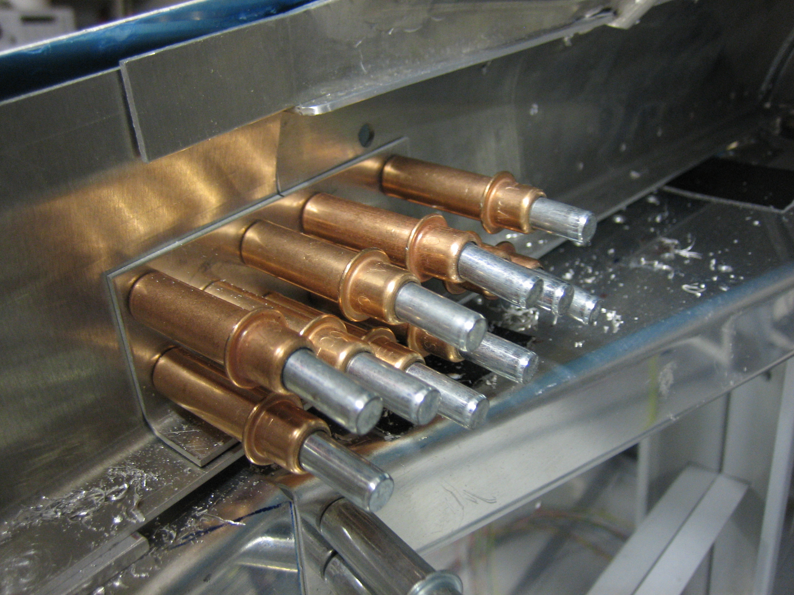
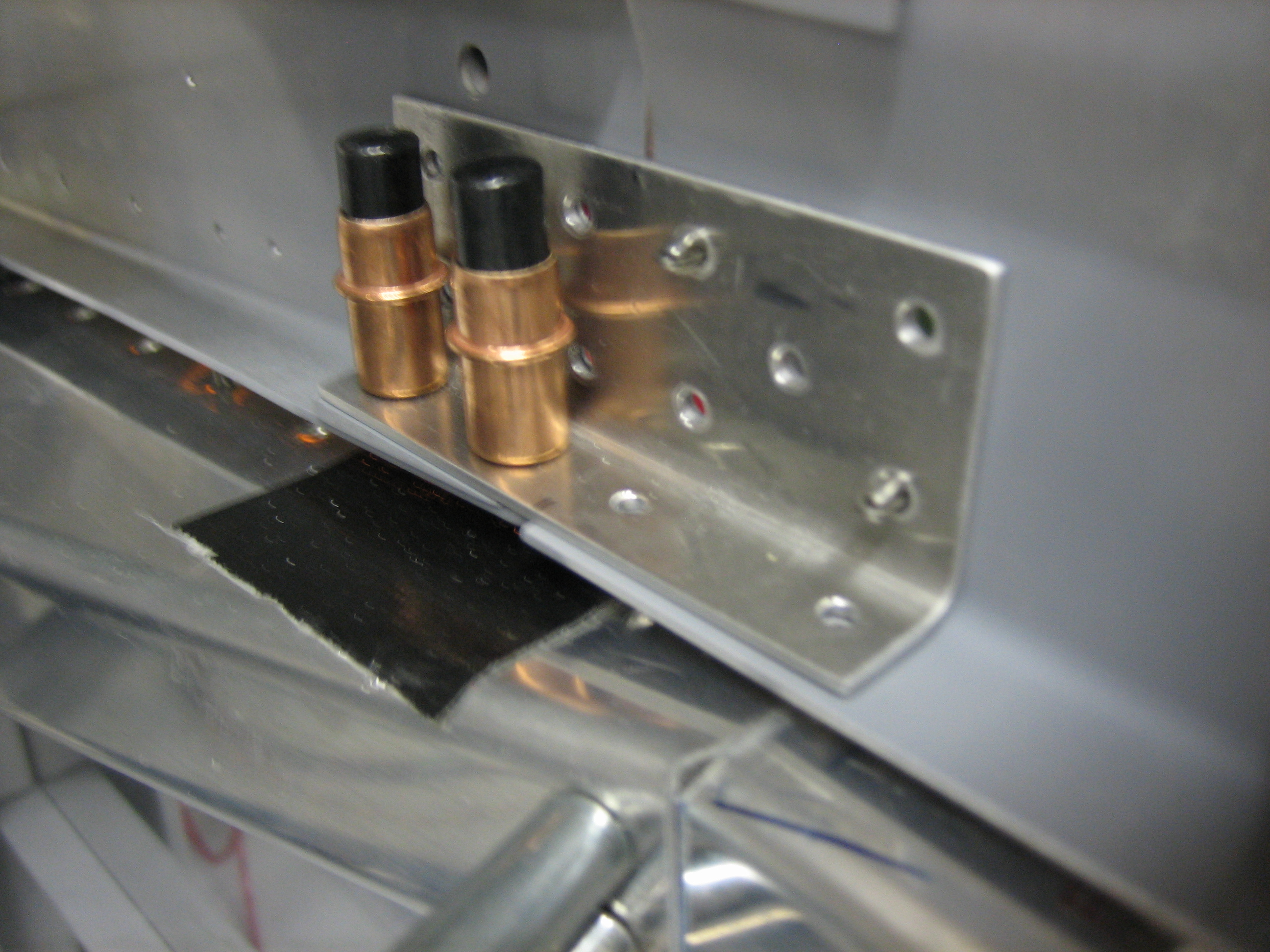
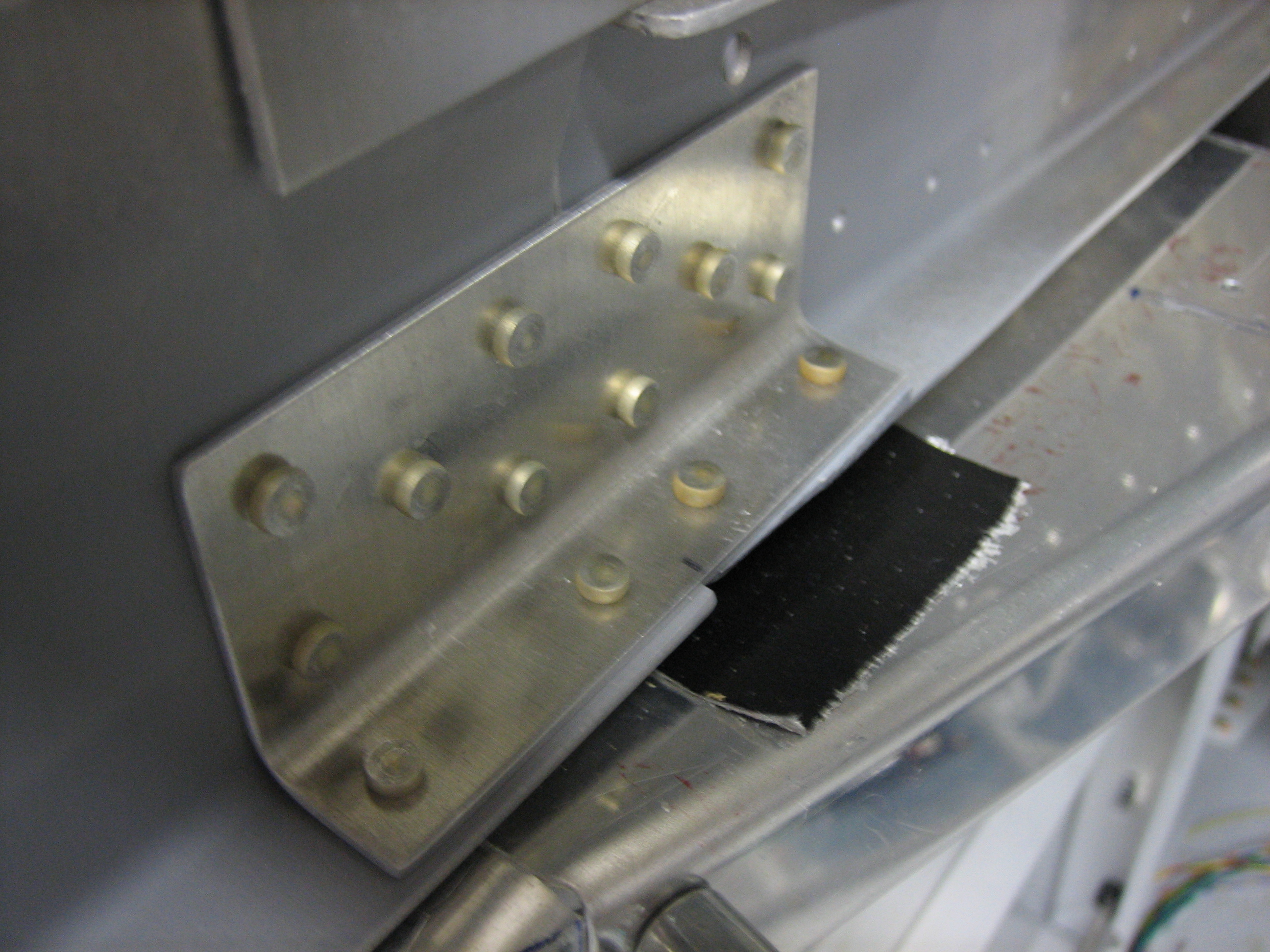
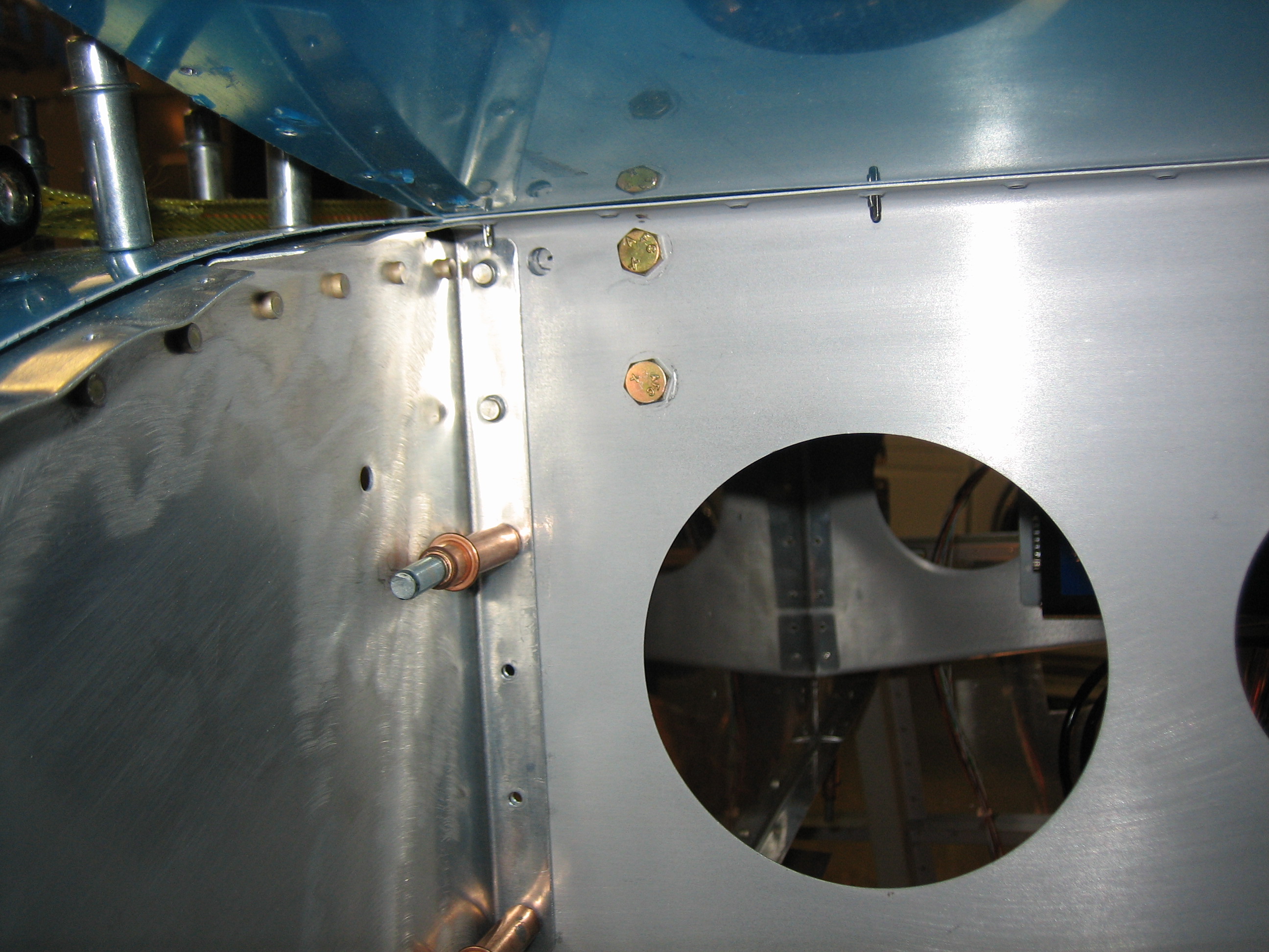
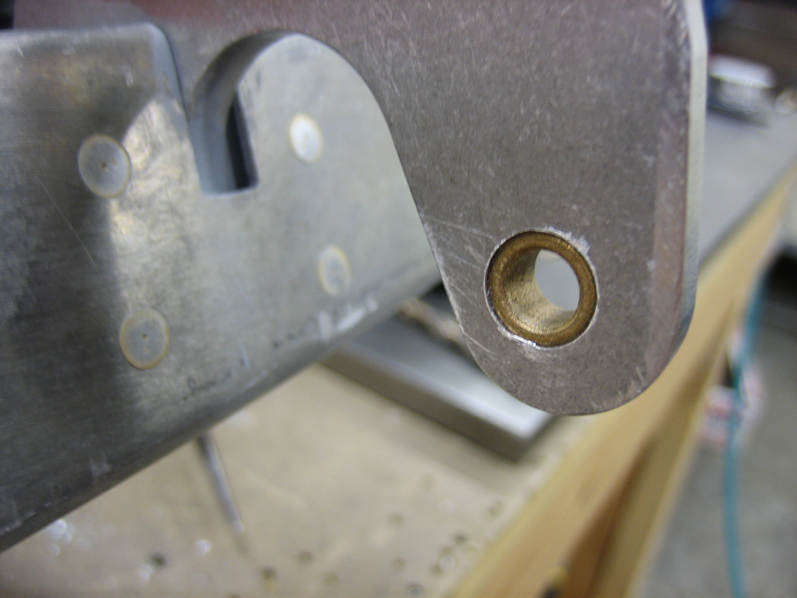
I then opened the hole up to 23/64″ and then used my 3/8″ unibit to open the holes up to 3/8″.  Here you can see the bushing block in the right hinge arm.

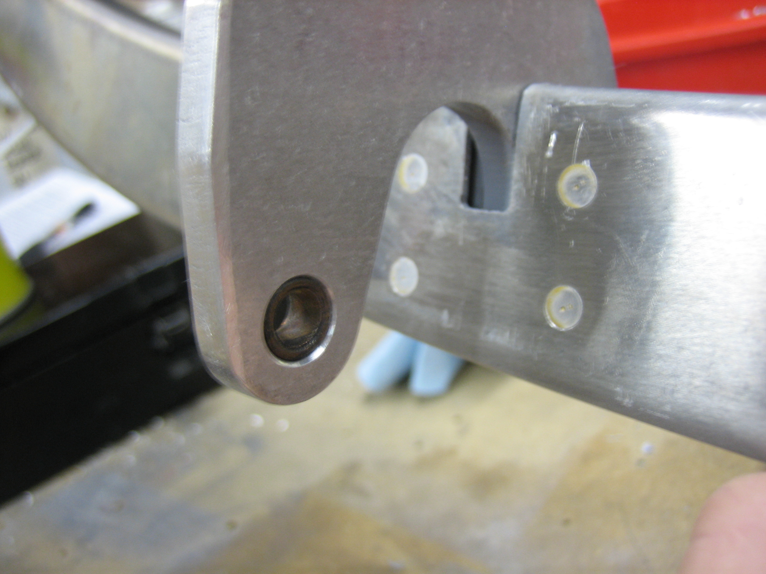
And here’s the bushing block in the left hinge arm.

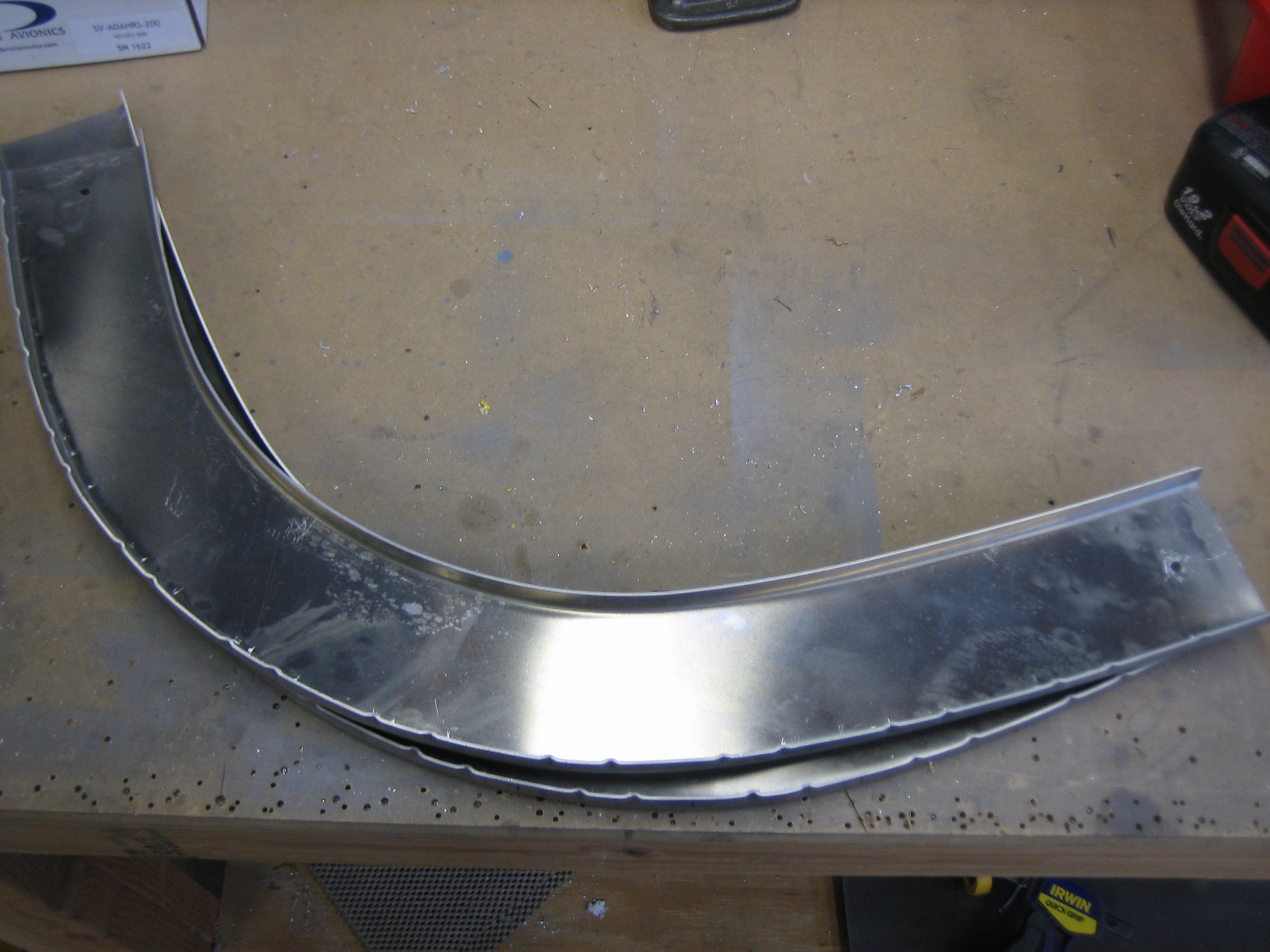
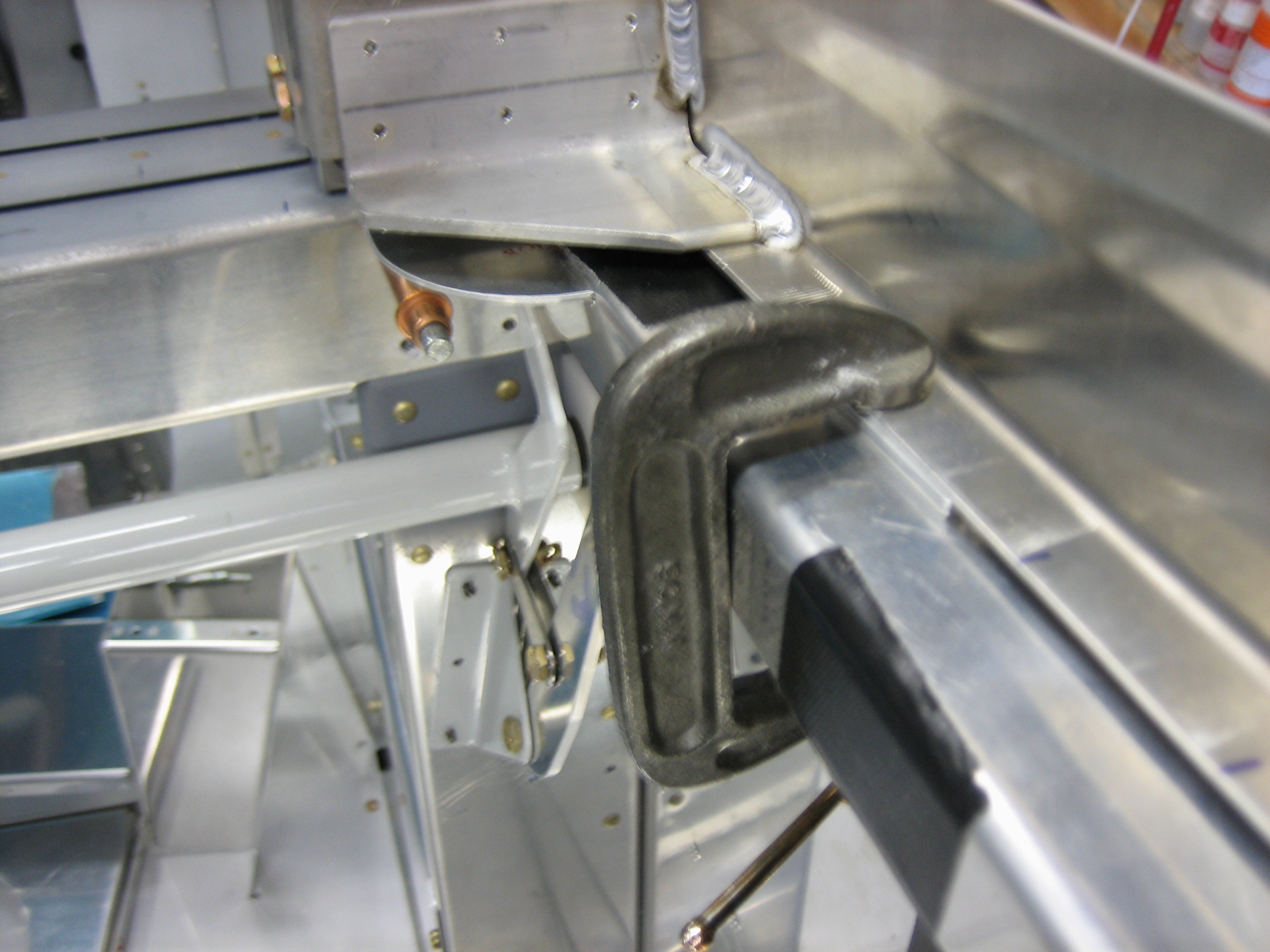
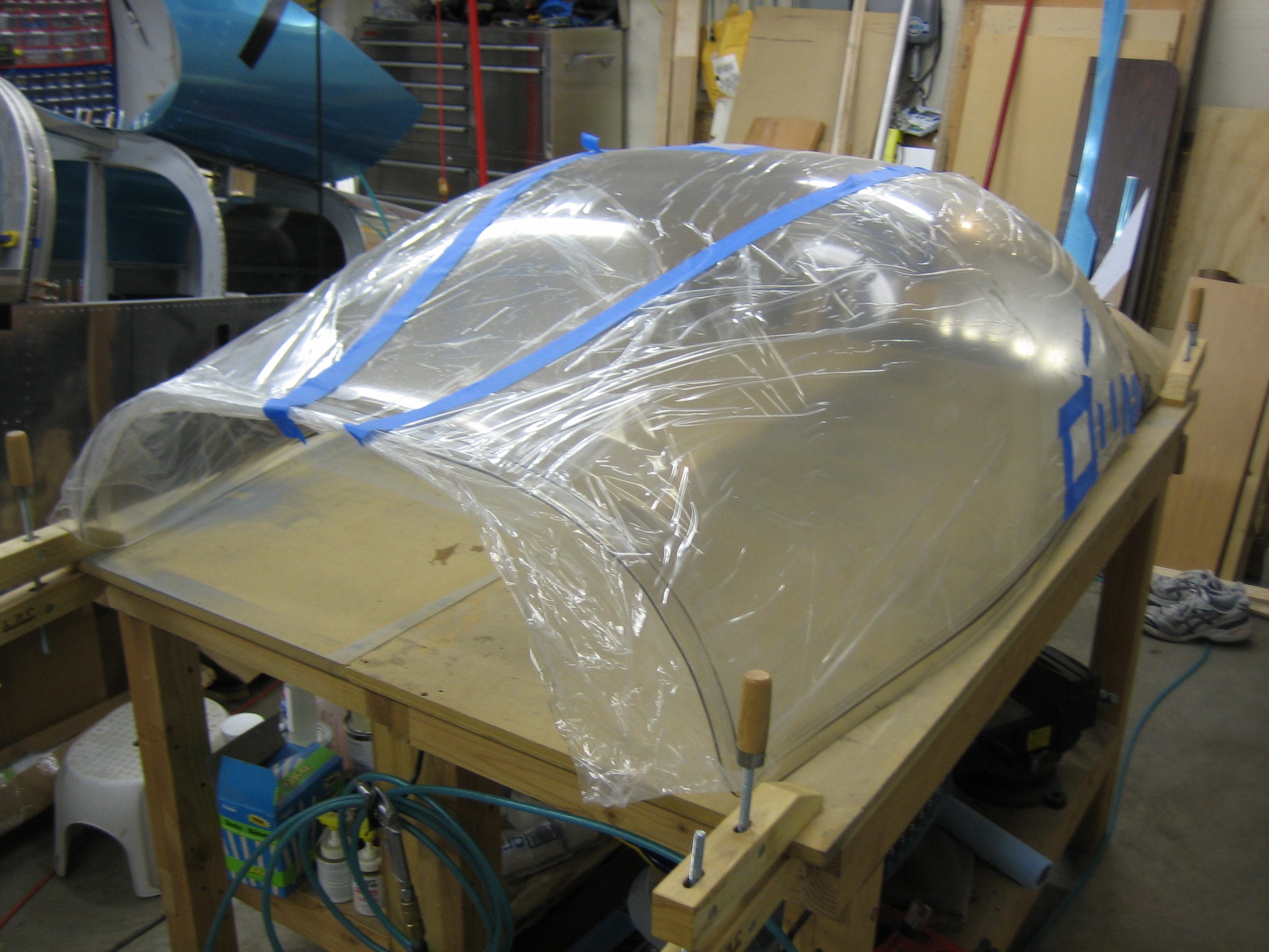
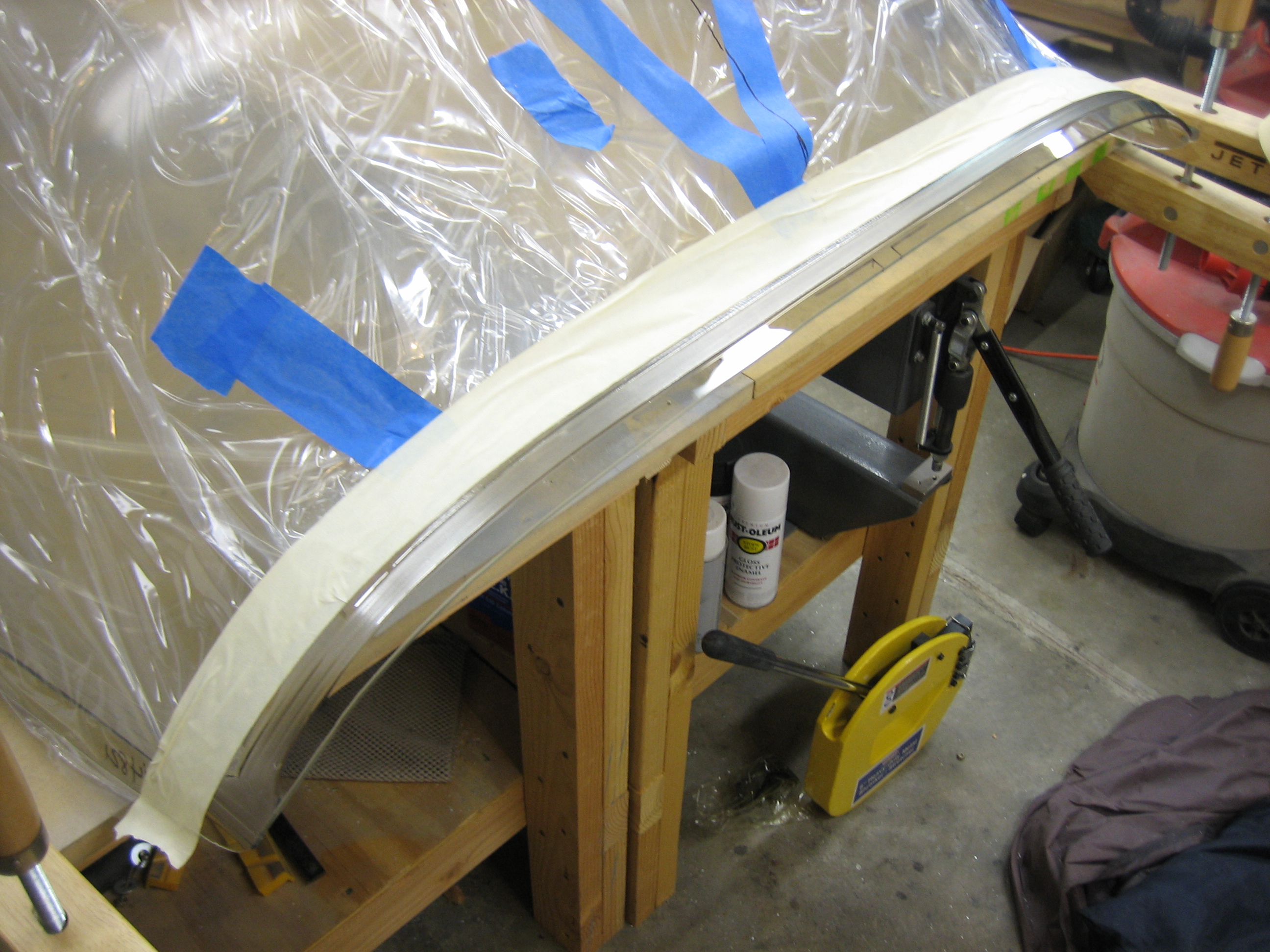
Finally, I put the canopy frame back on using some temporary pins and checked the motion.  As the instructions specify, the seal support angle interferes with opening the canopy frame.  I filed back the seal support angle a little bit and retried the frame.  After a few iteration, I have the canopy frame swinging smoothly.

Fit Canopy Frame

I couldn’t find anything obviously preventing the canopy frame from moving farther forward, but I suspected the seal support flange.  I unclecoed the outboard portion of the canopy frame skin and sure enough the forward channel of the canopy frame was pressed firmly against the seal support flange.

A few minutes with the vixen file removed the interference and now the canopy frame could be moved far enough forward that the skins butt together.  The plans want you to put a 0.020″ spacer between the skins, but the fit isn’t perfectly tight along the whole joint.  Instead, I’m going to butt the skins tightly together and then file the canopy skin to create a uniform gap along the whole joint.

I put a couple of ratcheting straps on.  One is pulling the sides of the frame inward to ensure the frame is the correct width.  The other is pulling the frame down to ensure it’s tight against the fuselage.

I also use a couple of clamps to make sure the canopy frame wall pulled down tight.

Started Canopy Frame

I reassembled the subpanel along with the hinge blocks and clecoed on the top skin.

I drew a centerline down the aft tube on the canopy frame.  This will be used to ensure the holes drilled through the top skin will go into the center of the tube.

Several other builders have commented that some of the welds prevent the skins from laying down properly.  The instructions mention this, but a picture is much more clear.  Here you can see that the weld would push the skin up about 1/32″ or so.

30 seconds with the vixen file and the weld is nice and flush with the angle.

The instructions also mention that the flange needs to be filed square with the face of the forward channel through the center.  A few minutes with the vixen file also took care of this.  Sorry for the blurry picture.

I clecoed the skin to the forward channel of the canopy frame and drilled most of the aft tube (the one I drew the centerline on).  I’ve seen a number of other builders have a problem with these holes not lining up with the centerline, but mine was almost perfect.

I fit the canopy frame for the first time, but almost immediately I had an interference problem.  I couldn’t get the canopy frame far enough forward.  I had anticipated interference from the hinge spacers, and a quick check with a mirror confirmed that was the problem.

I pulled the spacers (which involved climbing under the subpanel and removing the hinge blocks which was a pain in the ass).  I trimmed 3/16″ off the back edge.

I reinstalled the hinge blocks and spacers and then reinstalled the canopy frame.  Another builder commented that using a strap helps pull the skin down tight.

That resolved the issue.  I now have almost 1/8″ clearance between the hinge arm and the spacer.  Do yourself a favor and cut at least 1/8″ off the back of these spacers from the dimension Van’s specifies.  It will save you a lot of headaches.

With the hinge spacer interference resolved, I could get the canopy skin almost all the way forward.  I’m still getting some interference somewhere because I can’t seem to get these skins any closer.  I have almost 1/32″ on the left side.

On the right though, I have almost 1/16″ gap.  I need to determine where the interference is so I can pull these skins tight.

Fine Tuned Canopy Latch Handle

I received some UHMW tape from Van’s yesterday, so I disassembled the latch and put pieces of tape between the attach angles and the latch handle pieces.  I then filed out the openings so that the handle has about 1/64″ clearance all around.  This required removing and installing the latch handle countless times to get the fit just right.  I still have a little work to do to get this where I want it, but it’s operating smoothly now.

Finished Fabricating Canopy Latch

I laid out and drilled the holes on the attach angles.  I also put four layers of blue painters tape between the angles and the latch pieces.  These add about 0.018″ of clearance between the pieces to make room for the 0.016″ thick UHMW tape that will be installed in the completed assembly.

I then clamped the latch in place.

And backdrilled through the skins.  This is the opposite of the way the Van’s plans specify, but it ensures that the latch is perfectly centered in the slots and the holes are centered in the attach angles.

Finally, I fabricated the connecting rod that ties the latch handle to the idler.  I ended up needing to make mine about 1/8″ longer than the plans specify.  The tube has to be cut to length and then the ends tapped out to 1/4-28 for the rod-end hardware.

Here’s a closeup of the handle end.  You can see how I had to notch the upper attach angle for the rod-end.

With the handle in the closed position, you can see how the idler is pulled forward which pushes the latch finger into the slot on the bulkhead.

Here is the latch handle pulled back all the way.

With the latch handle pulled back, you can see how the idler is pushed back which pulls the latch finger forward.

More Work on Canopy Latch

I took a break from the canopy latch handle and went back to the latch itself.  I trimmed the lower ear as specified in the plans for weight savings.  After taking this picture, I used the touch-up paint that matches the powder coat to cover the bare metal.

Next, I drilled the bushing blocks out to full size and temporarily bolted the latch into place.

Finally for this evening, I fabricated the idler and linkage.  The upper hole in the idler will connect to a pushrod whose other end is attached to the canopy latch handle.  Here’s the mechanism in the latched position.

And here’s the mechanism in the unlatched position.

Cut Canopy Latch Slot

I double checked the measurements I made last night and found them spot on, so I got started cutting out the slots.  I used a unibit to remove most of the material.

I then spent a few minutes with the hand nibbler removing most of the rest of the material to just inside the lines I’d marked.

I then clamped a steel straight edge along the line I drew and filed down to the line.  The steel straight edge serves two purposes, it helps ensure that the filed edge is perfectly straight and it prevents filing past the line since the file basically stops cutting when it hits the straight edge.

After about 30 minutes of filing, the latch fits pretty well in the slots.  I had to round the corners of the latch pieces slightly since I didn’t want a sharp inside corner on the skins because that could lead to cracking.  At this point, the latch operates pretty well; good enough that I can go ahead and drill the attach angles to the skin.  Once the final position of the latch is defined, I’ll finish filing the edges to provide even clearance all around the latch.

Worked on Canopy Latch and Engine Start Button

I stopped by the hardware store this morning and picked up some 7/32″ and 9/32″ brass tubing.  I then drill out the latch pieces so that these are a press fit into the holes.  This will allow the brass tubing to rotate around the bolt.  This totally fixed the sloppy fit and the bolts are a slip fit through the holes now.  I’m not going to install these permanently in the holes yet since I’m planning on having the latch components hard anodized.

I also drilled the latch attach angles to the latch components.  Here is the latch temporarily assembled so that I can check the clearances and movement.

On the other side, you can see how the latch sits proud of the attach angles.  This is because the attach angles will sit flush with the inside of the skin, but the latch components should be flush with the outside of the skin.  The skin is 0.032″, but I positioned these currently 0.036″ proud of the angles.  After I get them back from the anodizers, I’ll file the outside faces flush with the side of the plane since they’ll be painted the same color as the exterior.

I’ve temporarily clamped a piece of scrap material across the outside face to simulate the skin since the skin acts as a stop for the forward catch.

To open the latch, you push forward on the forward knob until the aft part is released.

Once the latch is released, the aft part pops back.

It can then be pulled aft to release the canopy.

Finally, I laid out the cutout for the side skin.  It’s late, and I want to do this when I’m fresh, so I’ll start this tomorrow.

I wasn’t completely tired, so I wanted to figure out how the engine start switch will be wired.  I don’t think I’ve mentioned it before, but I’m using the engine start switch from a Honda S2000.  It has an integral light, but it’s really dim and can’t be controlled separately from power to the switch.

To solve this, I disassembled the switch, cut the traces to the light and wired them to the two unused pins on the connector.  If I end up using the Vertical Power VP-X, it can turn on the light when the start button is enabled.  I think I’m going to have to use a relay between this switch and the starter relay since I’ve heard the starter relay pulls about 4 amps and I don’t think this switch can handle that kind of current.  I need to confirm this though.

Started Canopy Latch

I started working on the canopy latch.  Instead of the latch included with the kit, I’m using the canopy latch from fairings-etc.com.  This will be perfectly flush on the outside of the plane instead of the protruding fingers of the stock latch.  The only disadvantage is the weight.  These are cut from 5/8″ thick aluminum stock instead of the 1/8″ thick stock used in the kit latch, so they’re quite a bit heavier.  I laid out a few lightening holes, but I may just drill holes part way through from the bottom side to remove weight without changing the appearance.

The quality of these as received is pretty marginal.  The cut edges are all very rough and will require quite a bit of hand work to smooth out.  Also, the predrilled holes are too large which makes for a sloppy fit around the pivot bolts.  I’m going to have to ream these holes out larger and fabricate some bushings to eliminate the slop.

The other problem with these latches is that the outer skin of the aircraft is used as the spring to keep the aft piece (on the left in the picture) engaged with the forward piece.  This seems like a pretty poor design as it will repeatedly flex the outer skin and could fatigue it over time. Fortunately, I knew this prior to purchasing the latch and ran across a good way to solve the problem on Roee Kalinsky’s site.