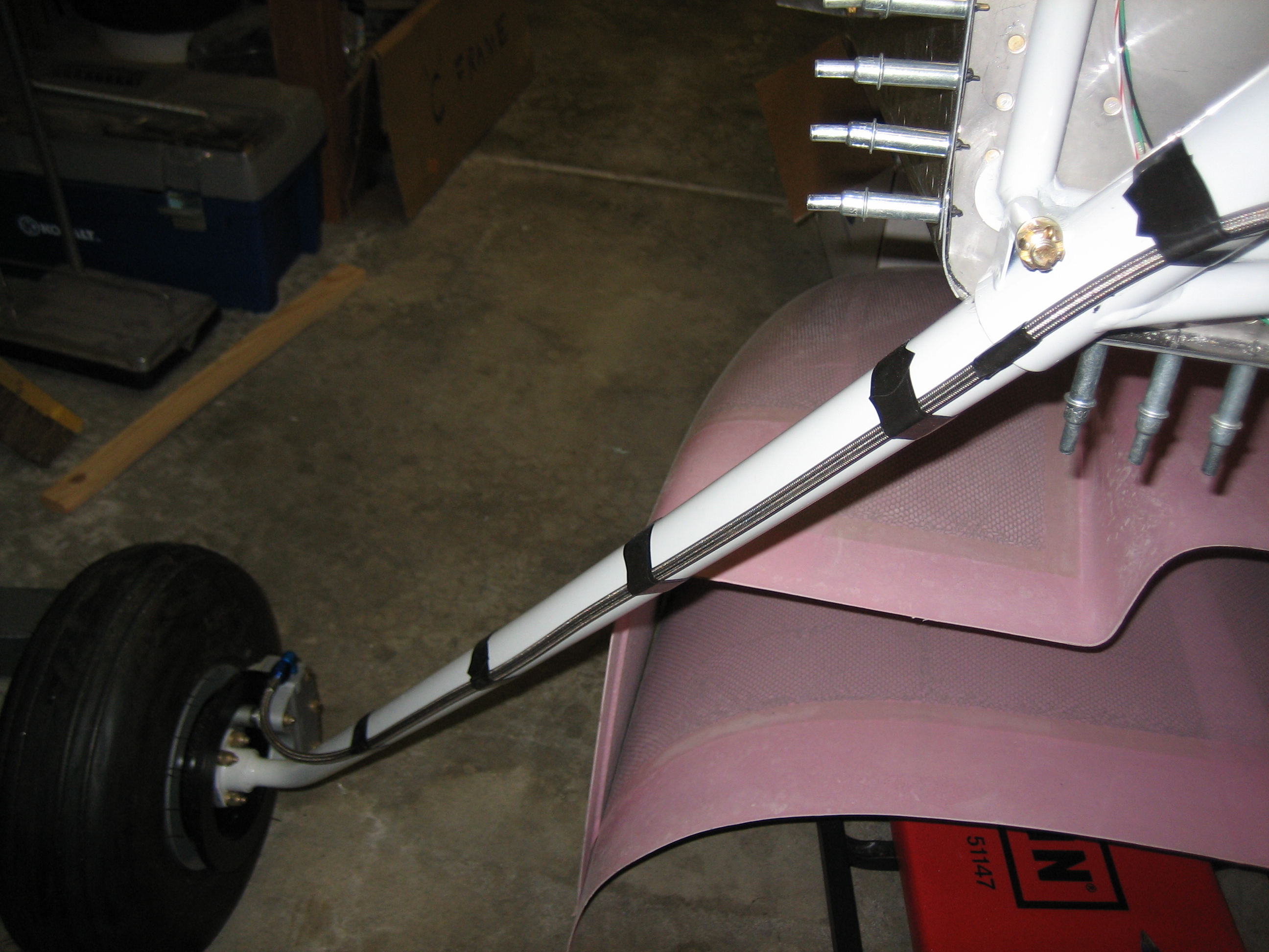
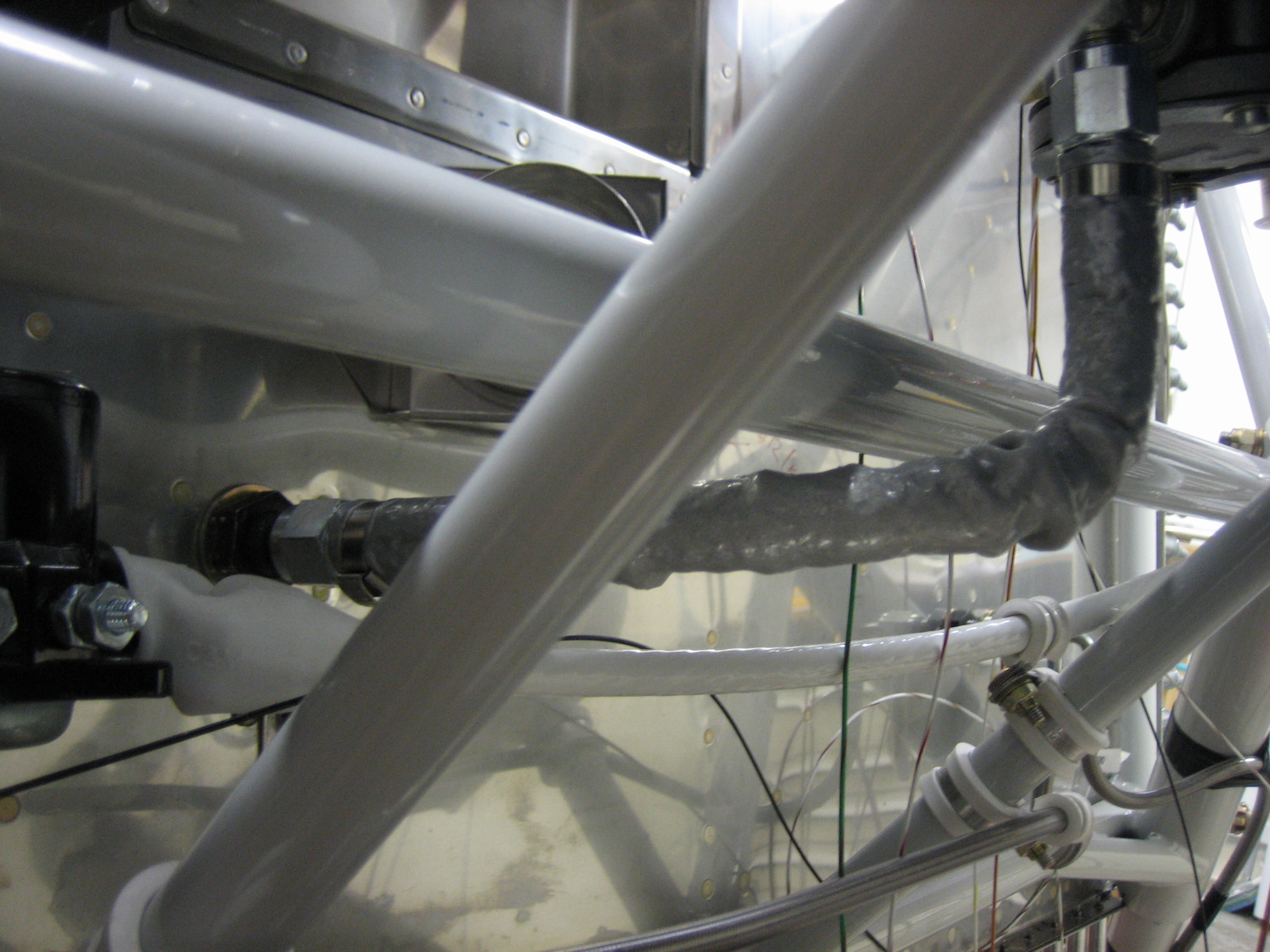
Sorry there were no updates for awhile. I flew the family down to Carlsbad, CA to take the kids to Legoland. It’s a fairly quick 3 hour flight from NorCal, and included a night IFR arrival, so that was fun. We got back yesterday, but I was dead tired so I didn’t work on the plane. My order from Bonaco did arrive while we were gone though, so I got started tonight by fitting the hoses. Here is the right brake line. I used strips of silicone tape (which only sticks to itself) to attach it to the gear leg. I also used a tiny strip where the line crosses the joint between the gear leg and the engine mount to prevent wear on the line.
The line then runs straight across the fuselage and is attached to the two center engine mount tubes using some adel clamps. I fit the cabin heat muff temporarily to ensure that the output tube wouldn’t interfere with the right brake line.

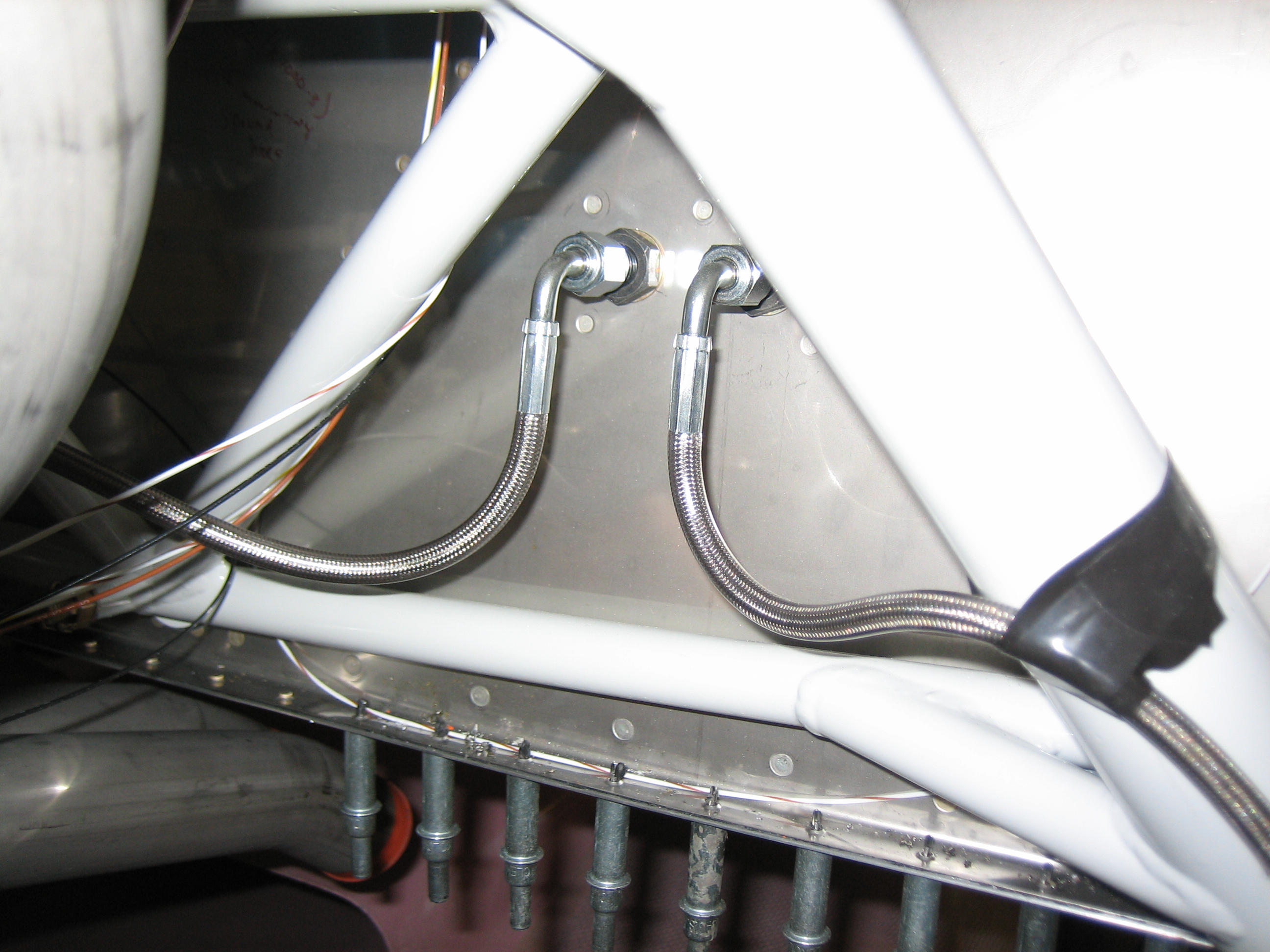
Here is where both left and right brake lines attach to the firewall penetrations.
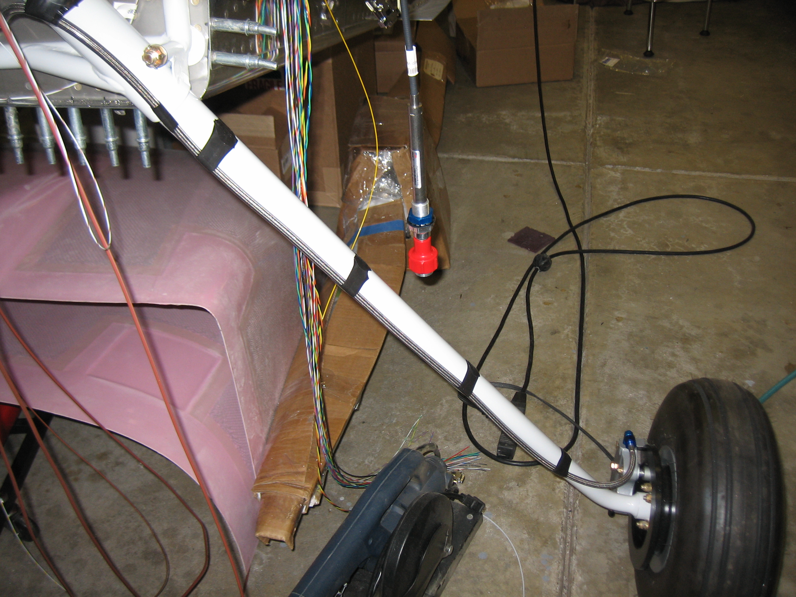
Here’s the left brake line for comparison. Notice that the line doesn’t need a big loop near the bottom for strain relief as the plans specify since we’re using flexible line. There’s only enough slack at the bottom to allow the brake caliper to slide off the pins.
I also installed the 3/8″ fire-sleeved fuel line from the firewall penetration to the mechanical fuel pump. This looks like the line bends rather sharply upward, but in reality it bends away from the camera before turning upward, so the curve is rather gentle. Torquing these fittings was a pain given how much stuff is in the way.
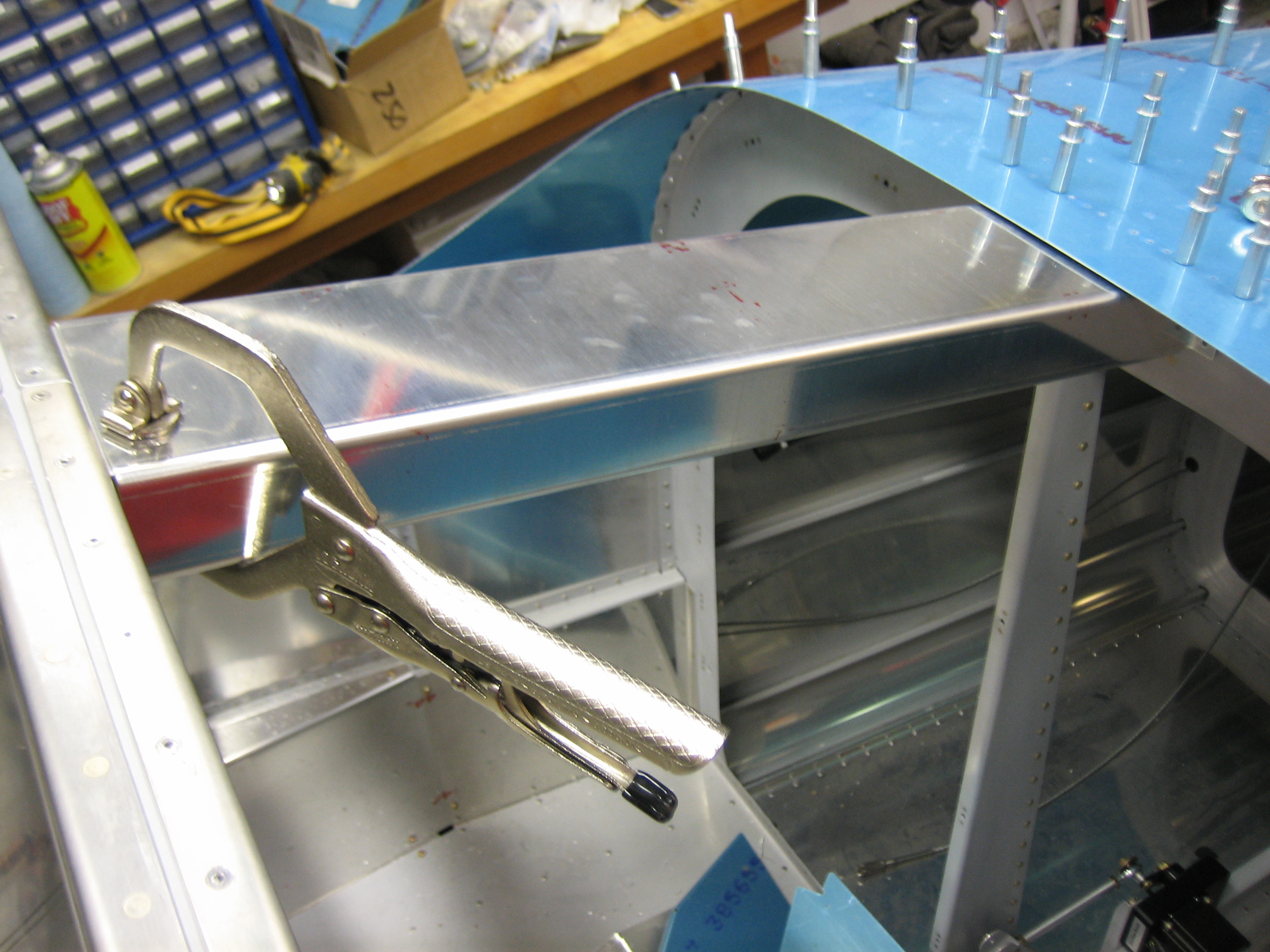
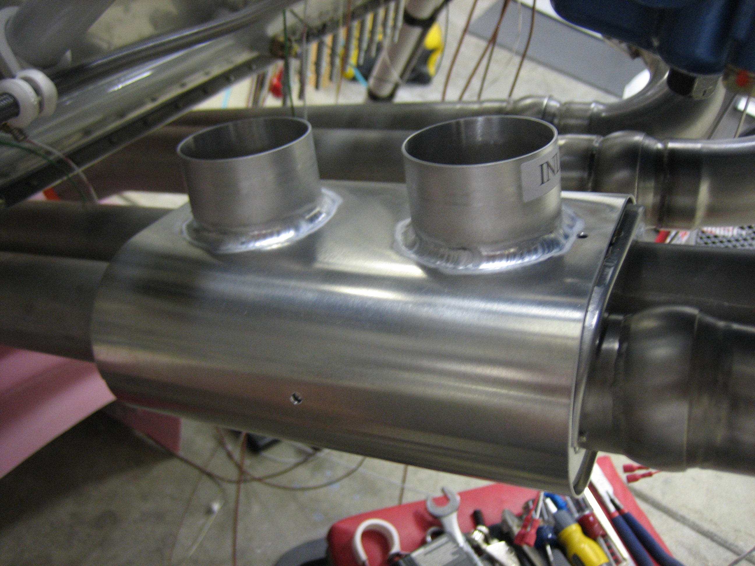
Here’s a better view of the cabin heat muff. You can see that it captures two pipes for better heat transfer.
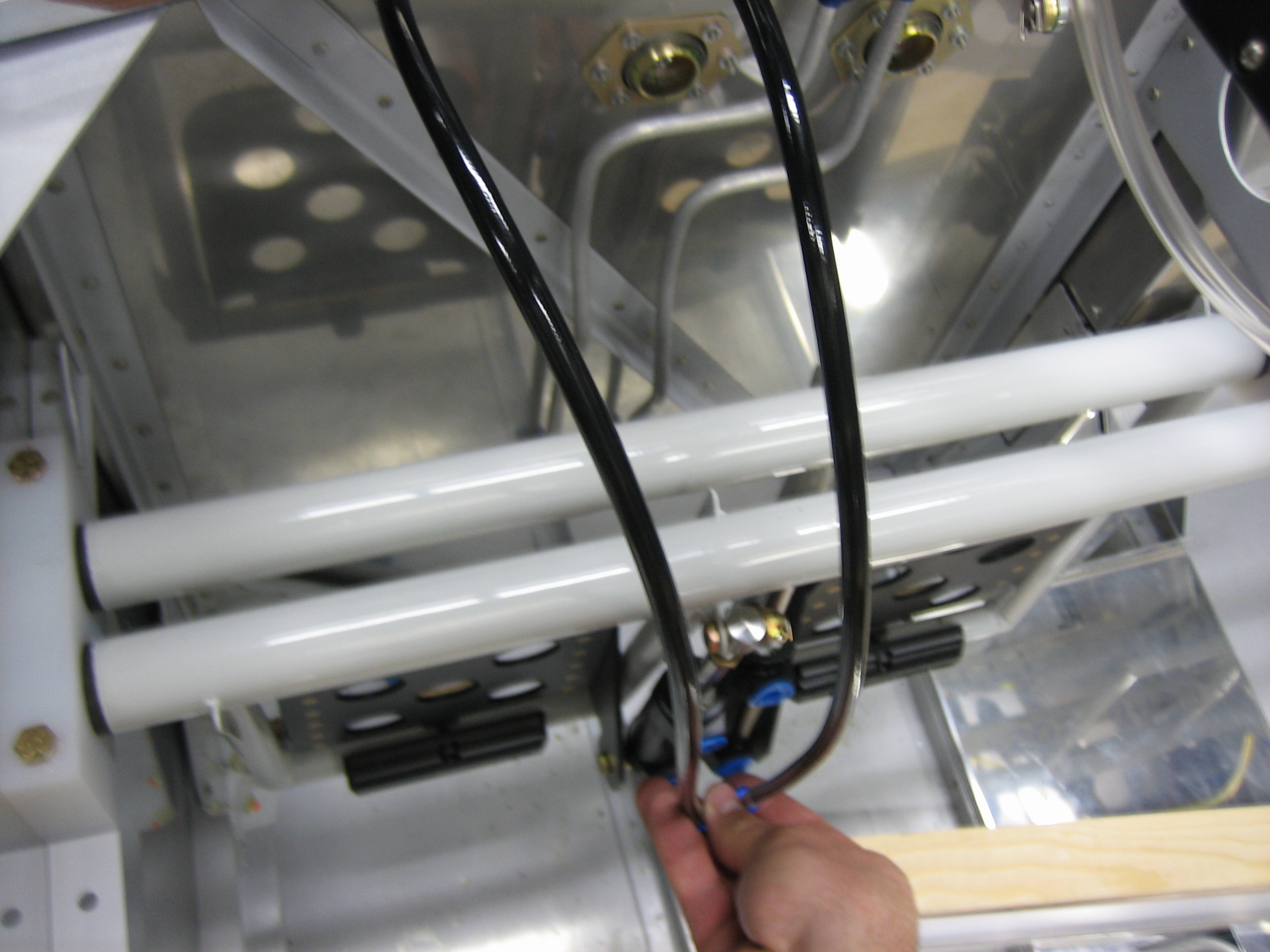
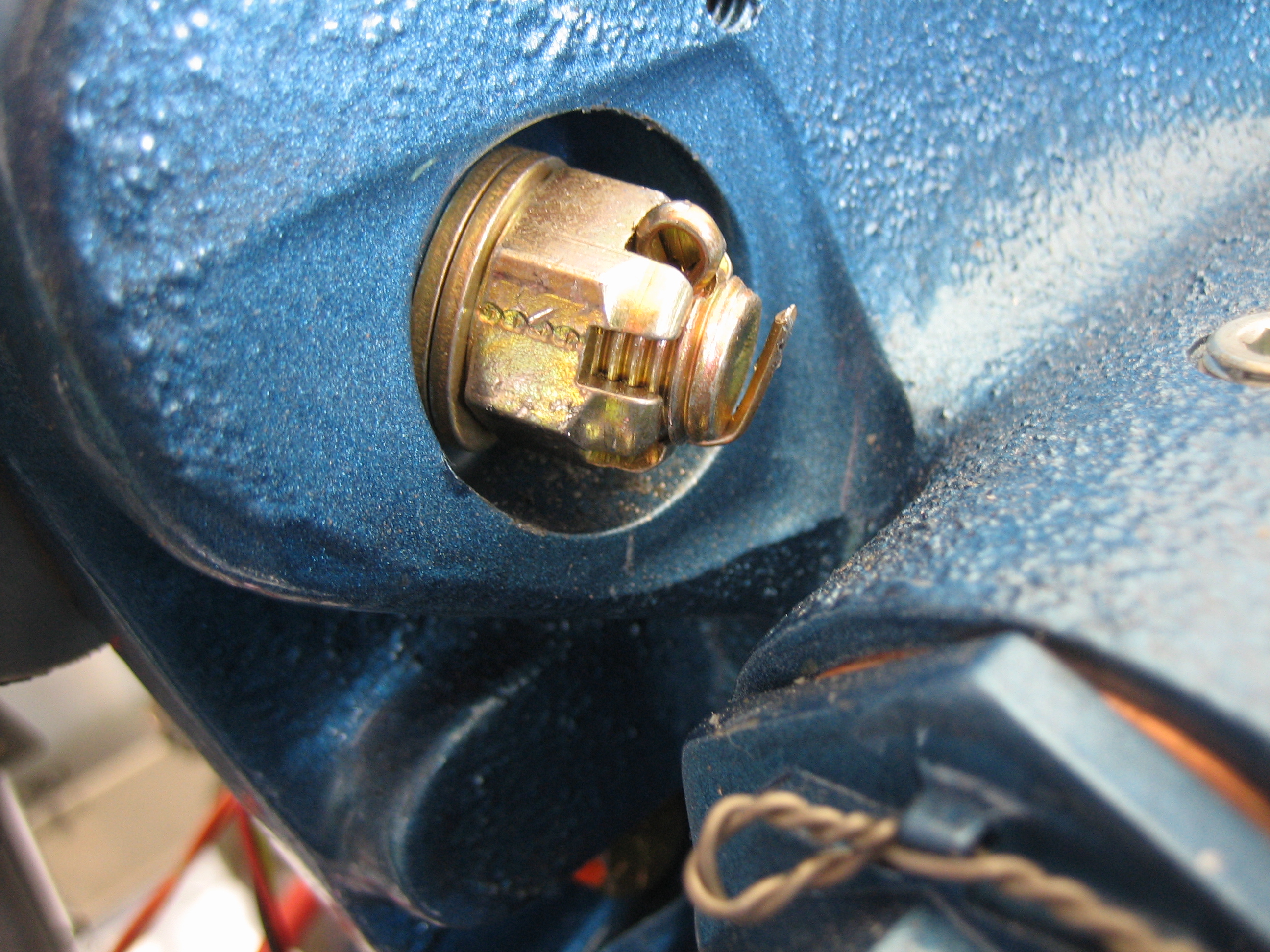
I also installed the tee fitting into the brake fluid reservoir and then installed the brake lines.
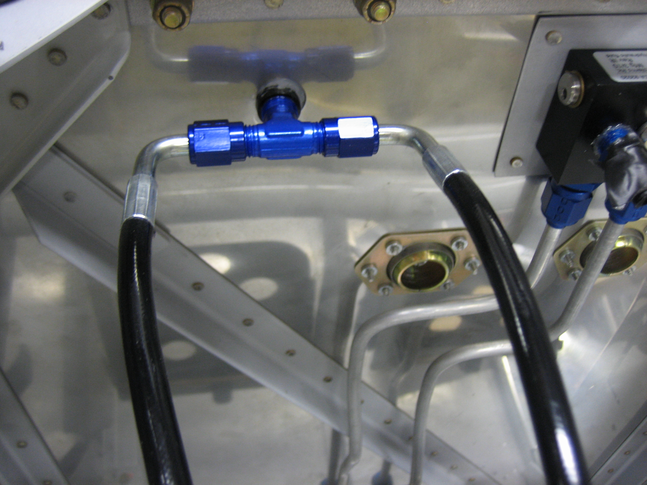
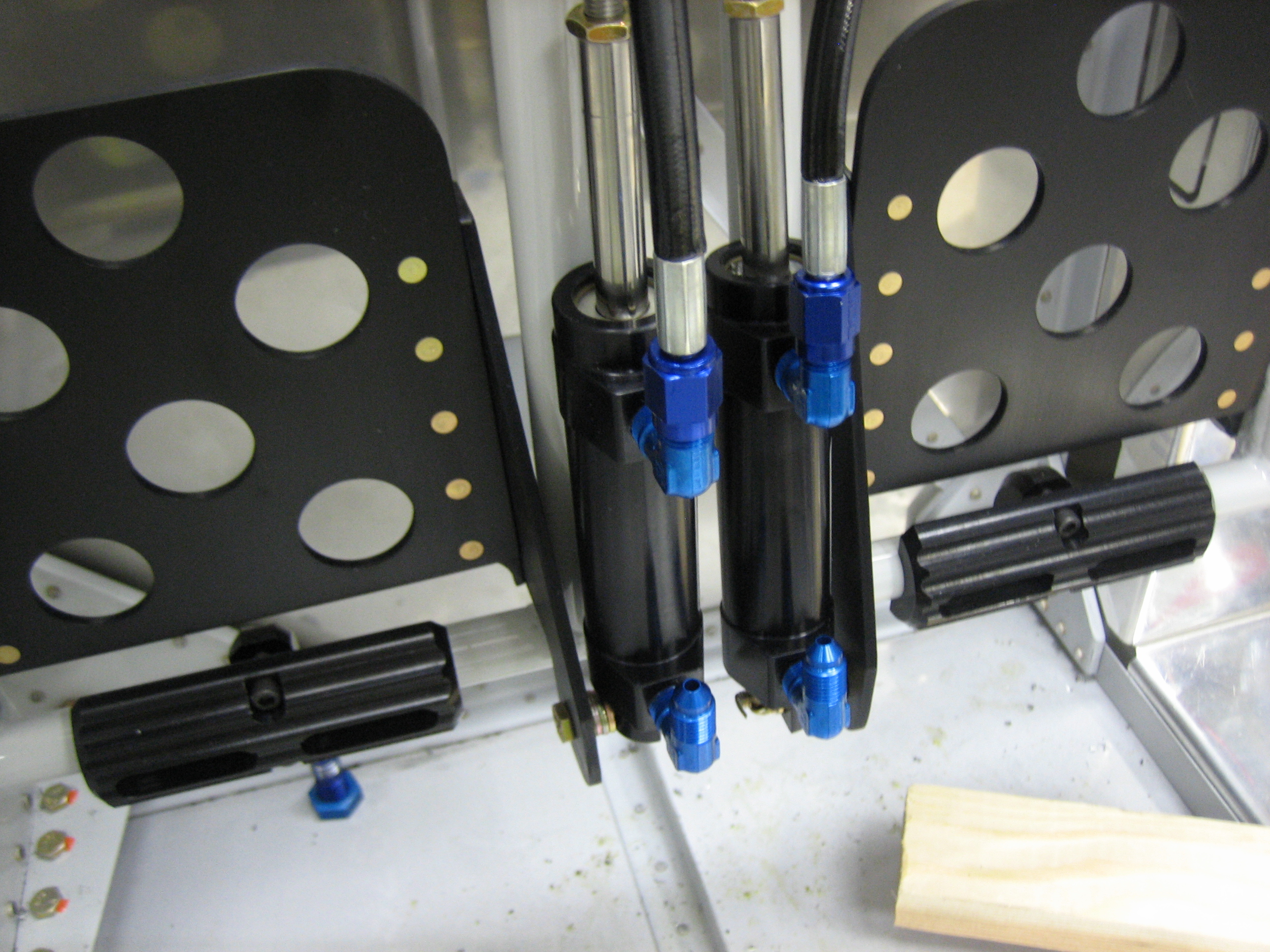
Here is approximately where these lines will be routed. These are 3/16″ stainless steel braided teflon lines with a black sheath over them to match the other all black brake components. I have some AN822-3D fittings on order that will be used to attach these lines to the master cylinders.