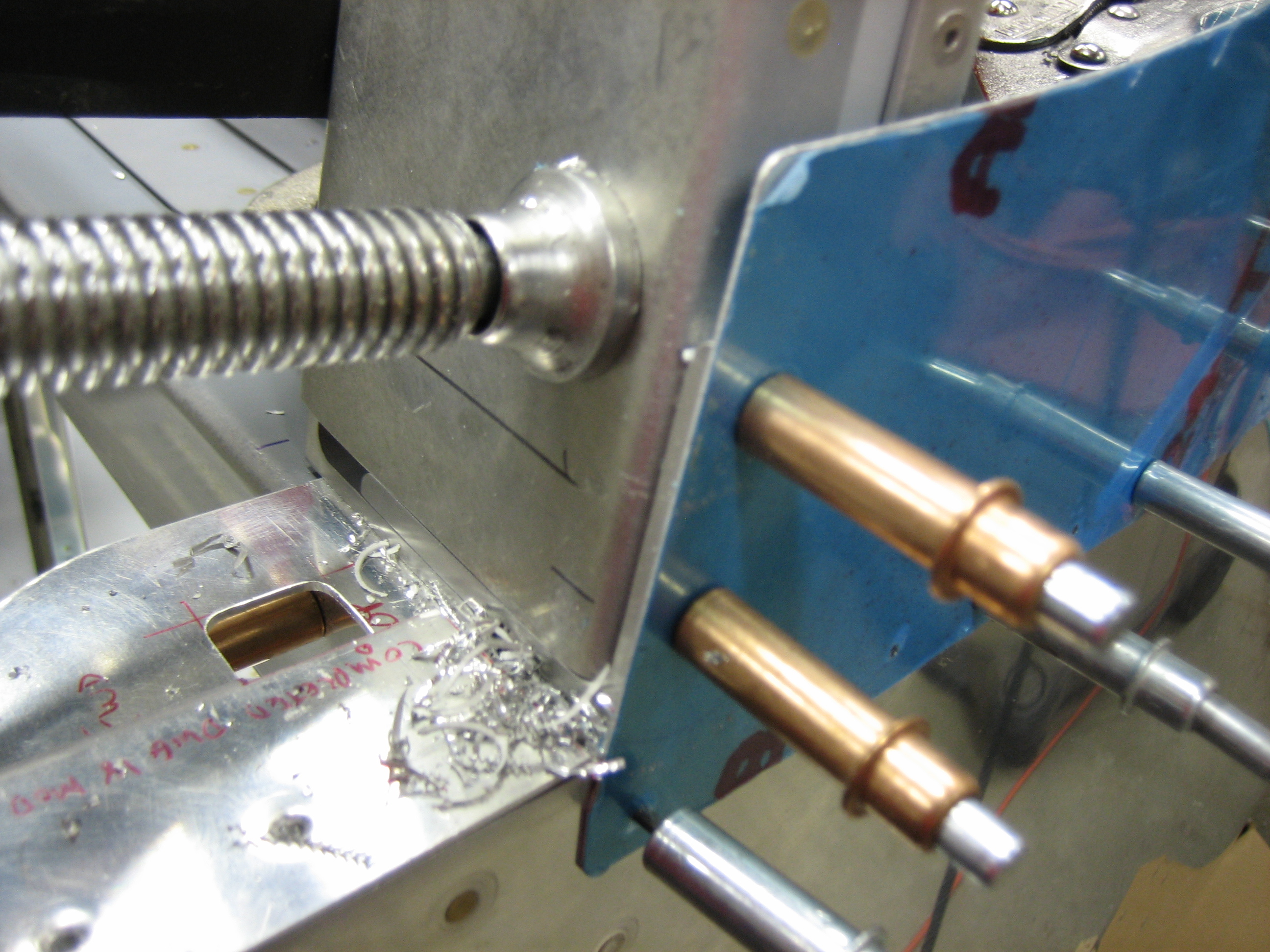
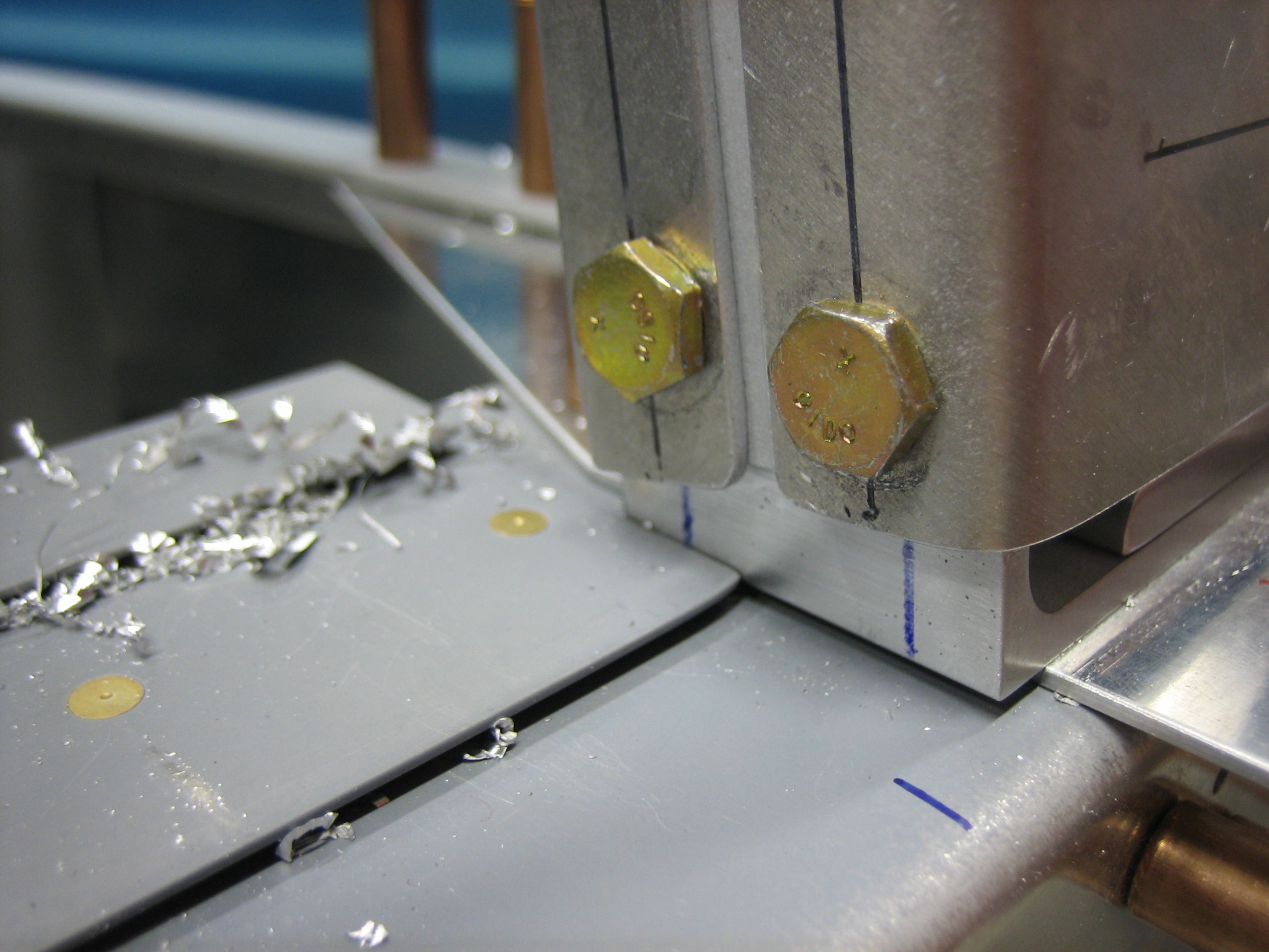
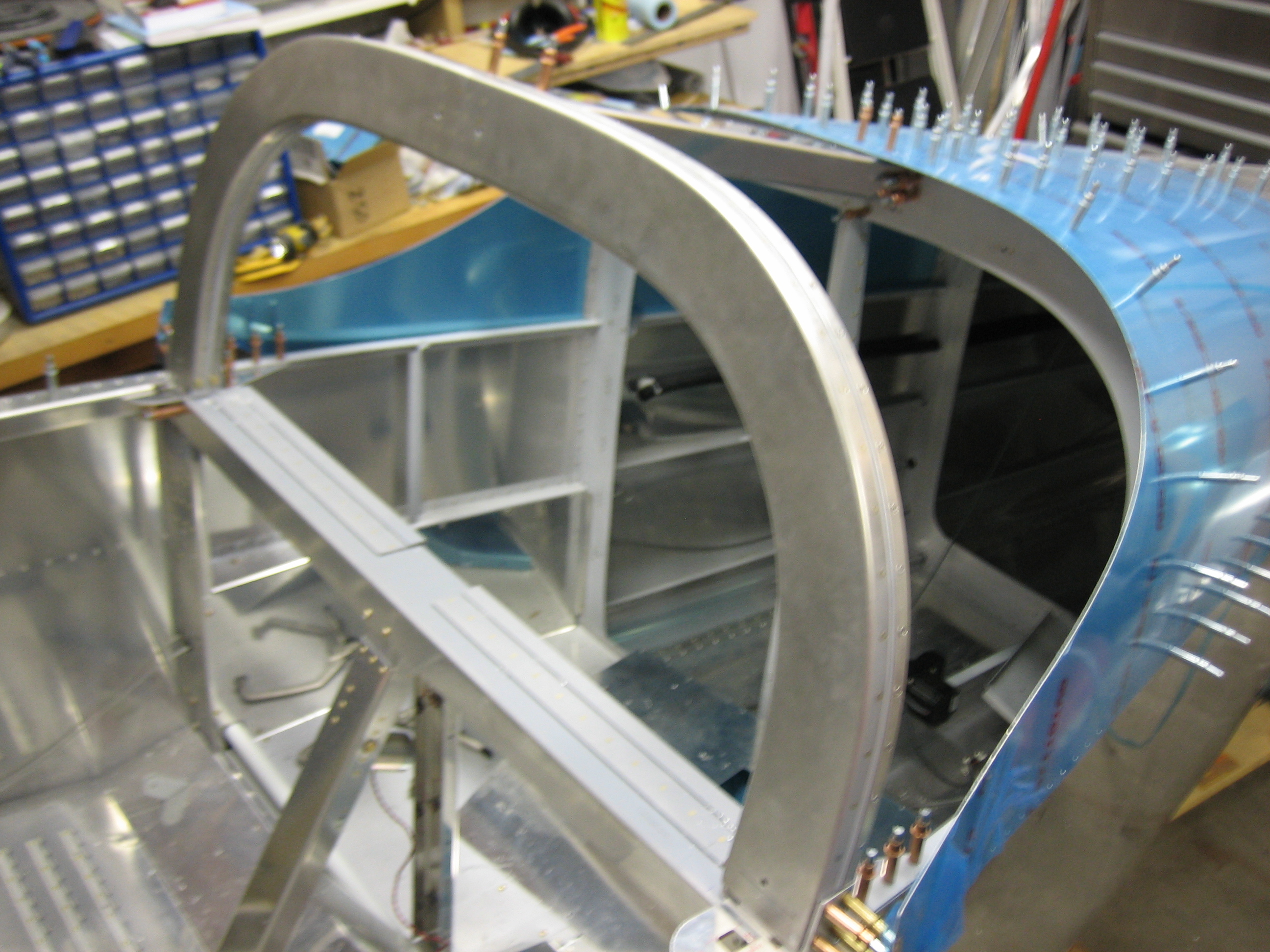
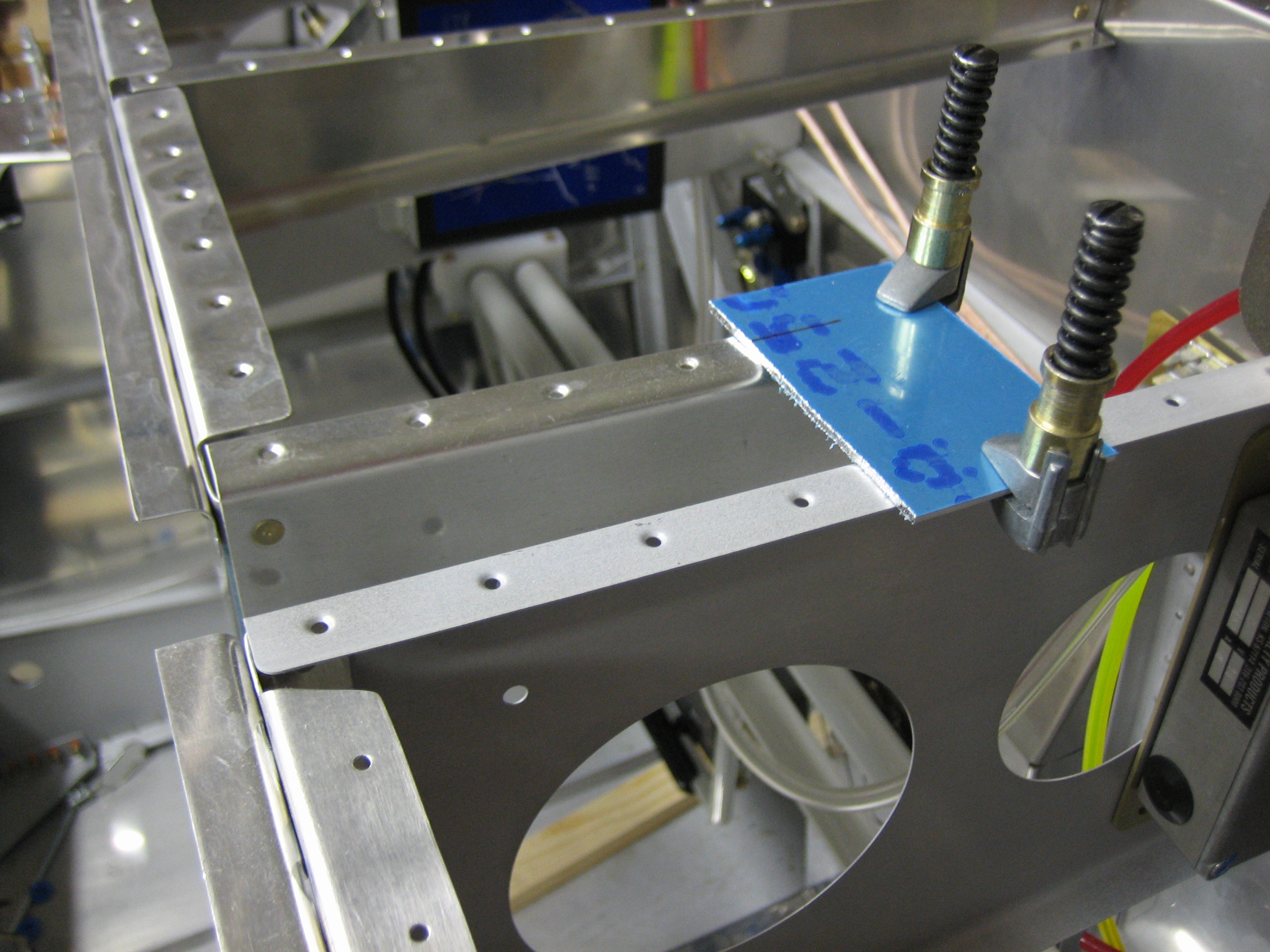
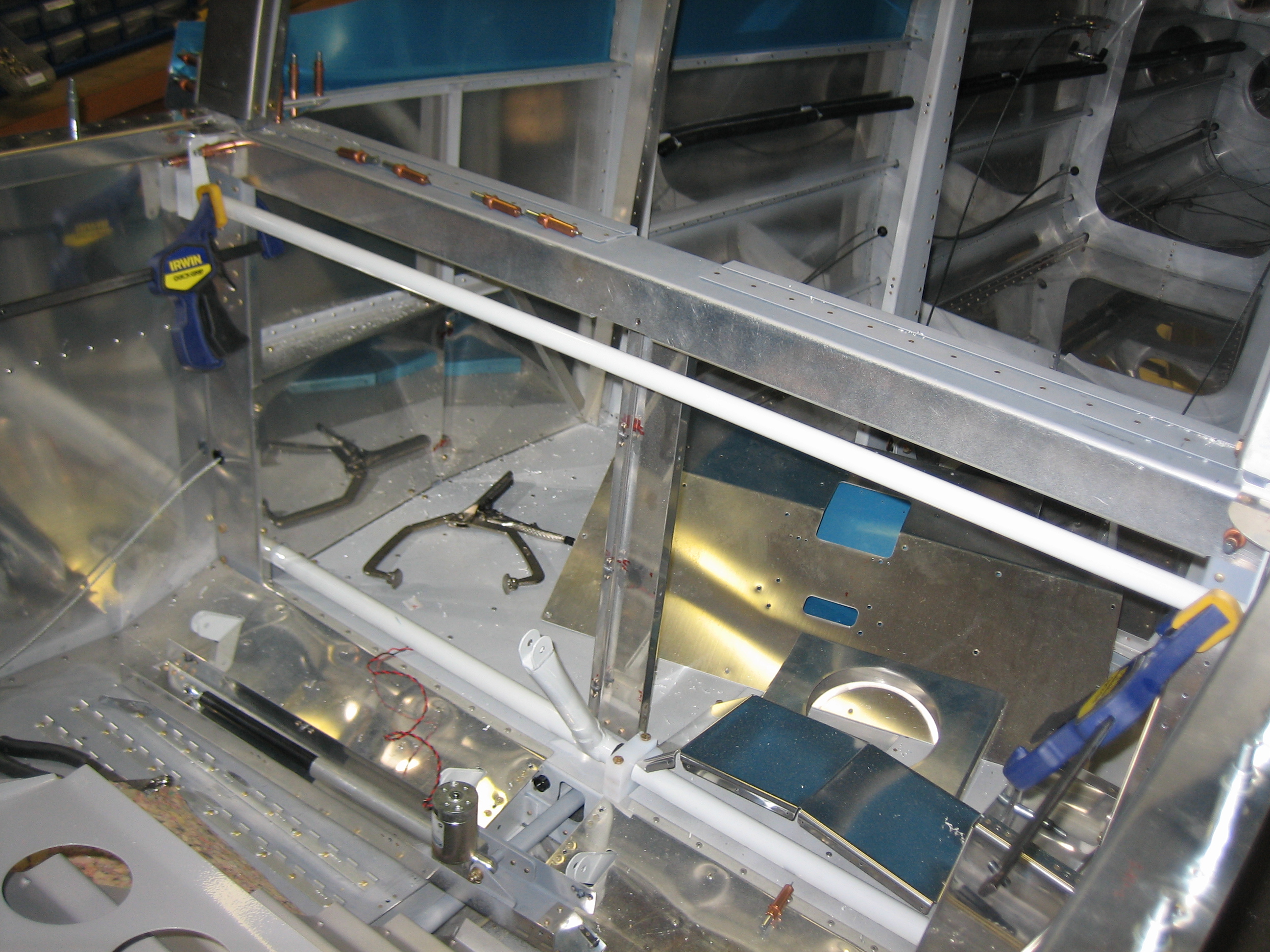
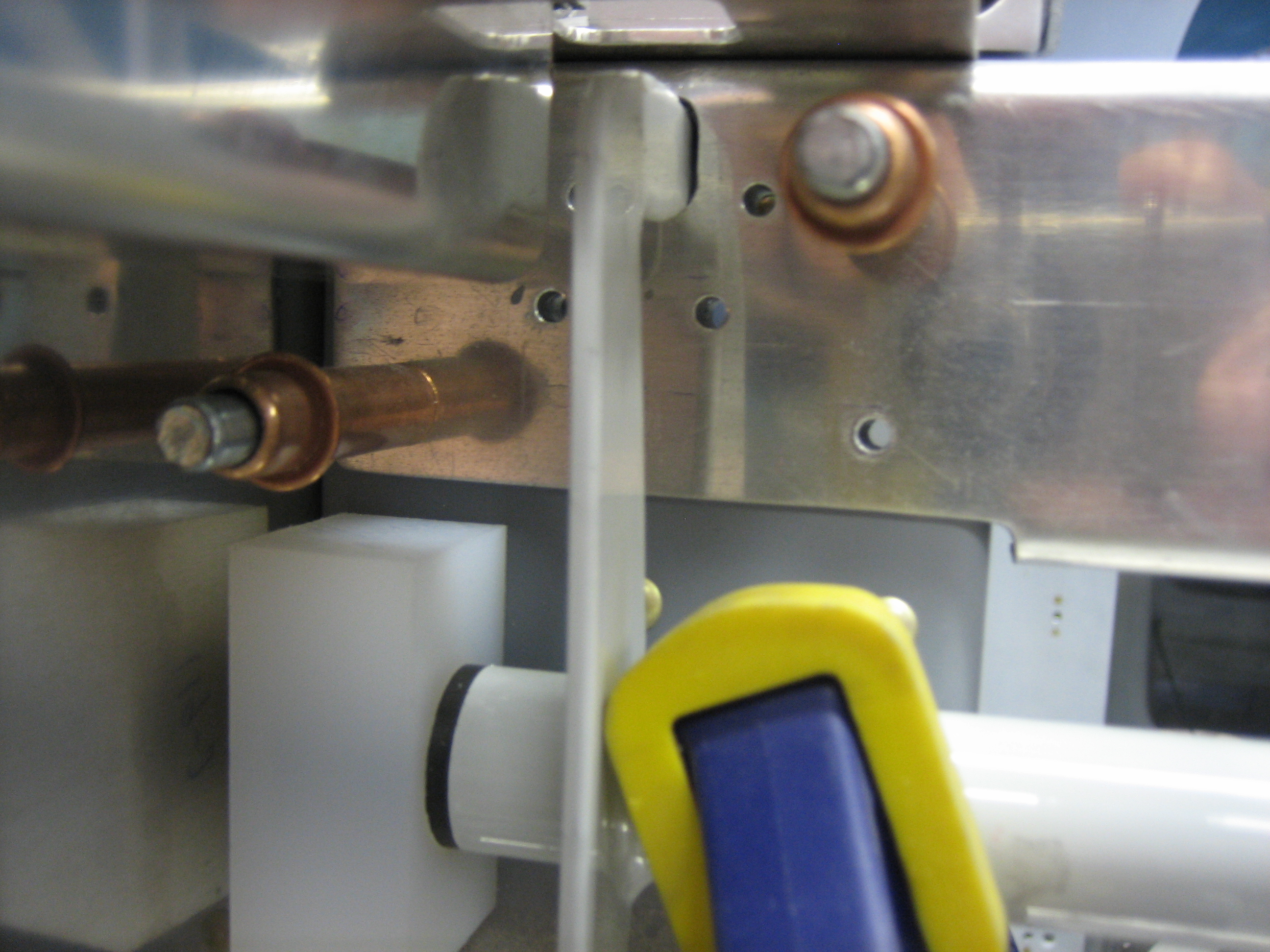
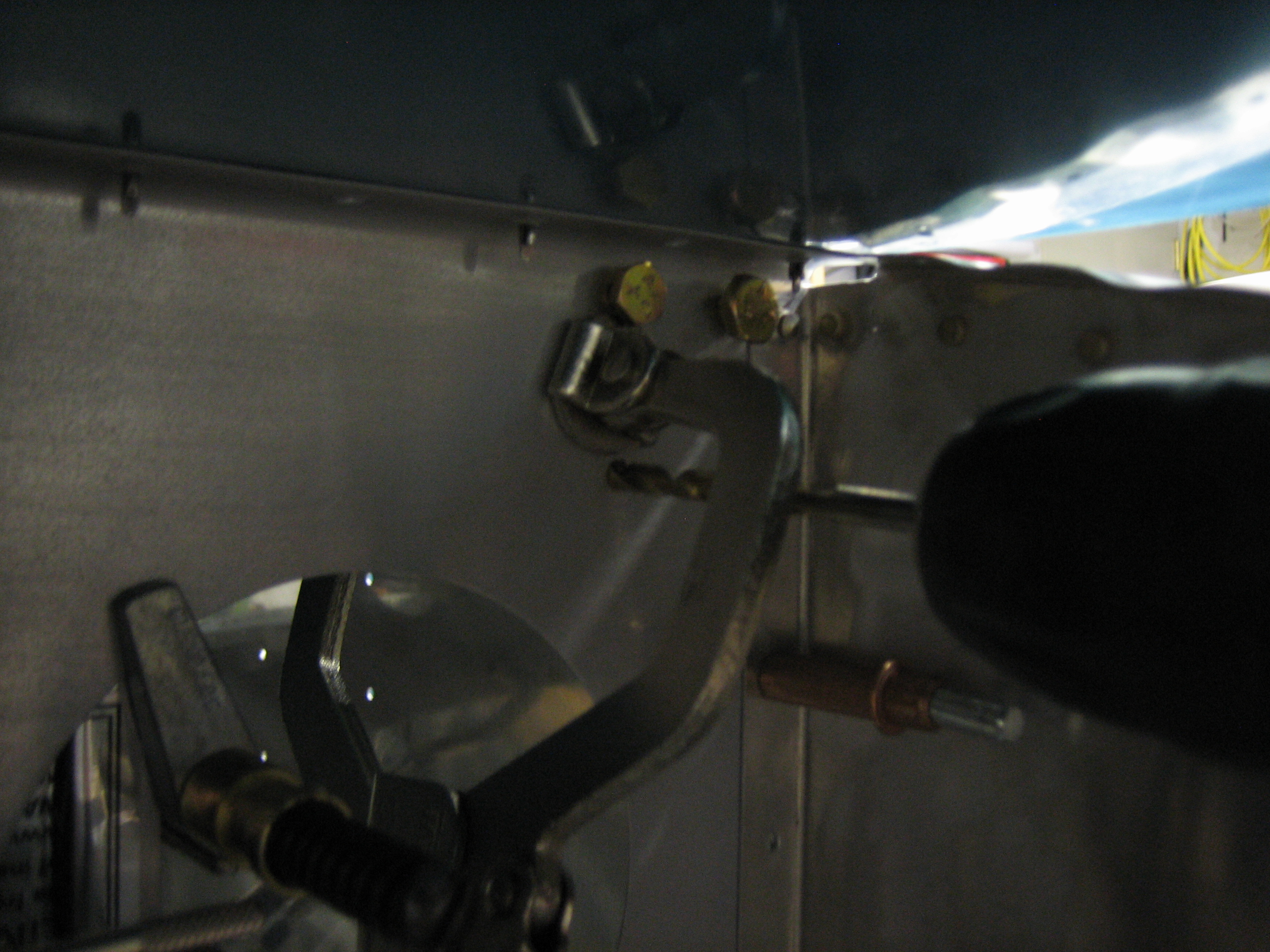
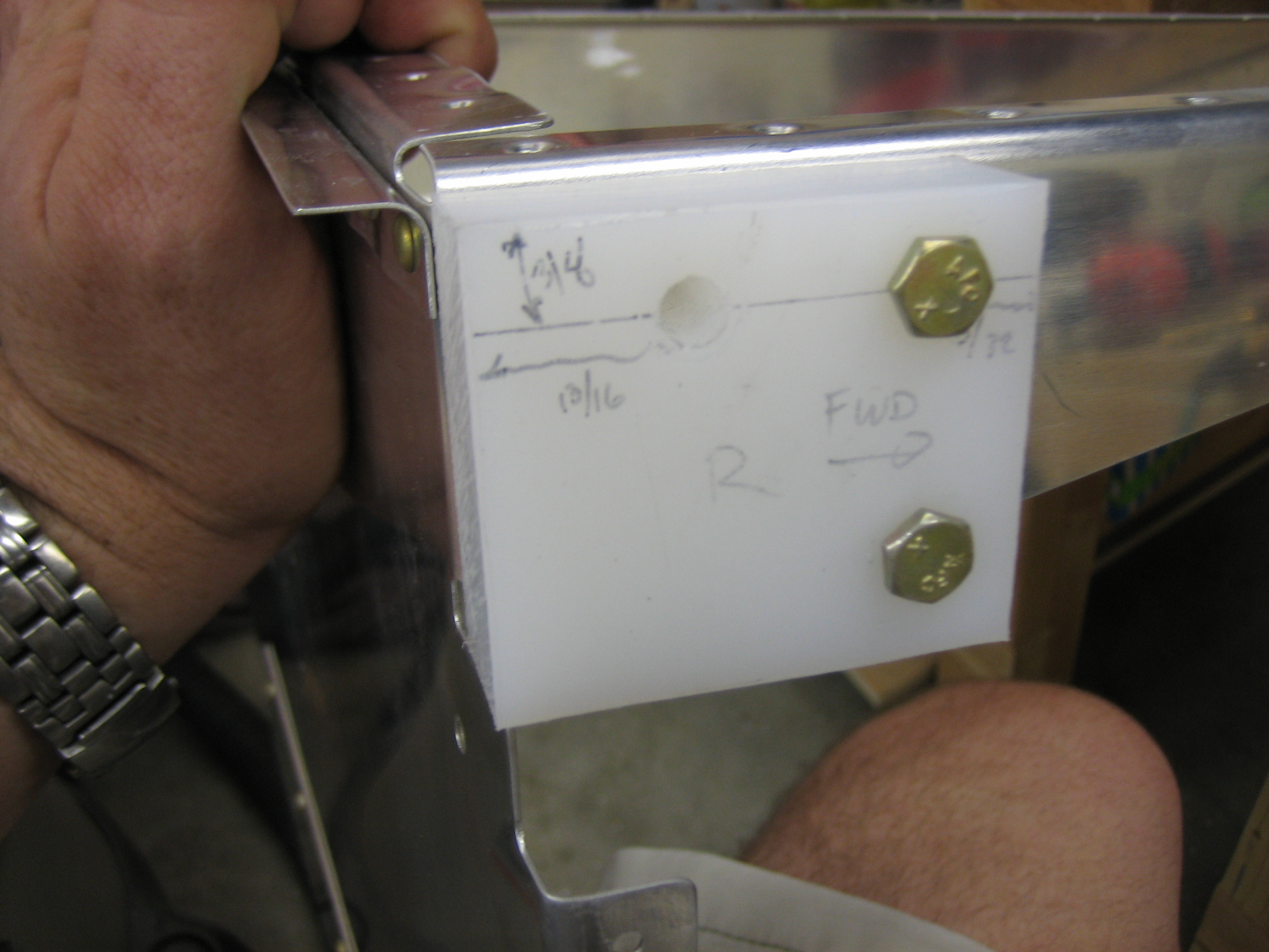
I had the cabin frame clamped 1/4″ above the location specified in the plans. I looked over the canopy plans as well as all of the fastener positions. This is the only issue I ran into. The lower #8 screw through the aft top skin would penetrate the cabin frame only 3/16″ above the lower edge. Since this hole needs to be drilled out to #29 and then tapped for a #8 screw, I didn’t think this was enough. I couldn’t lower the cabin frame much without the outer edges running into the inner radiuses of the attach angles. I didn’t get a picture of it, but I made a relief cut and radiused the edge to allow the cabin frame to drop down.
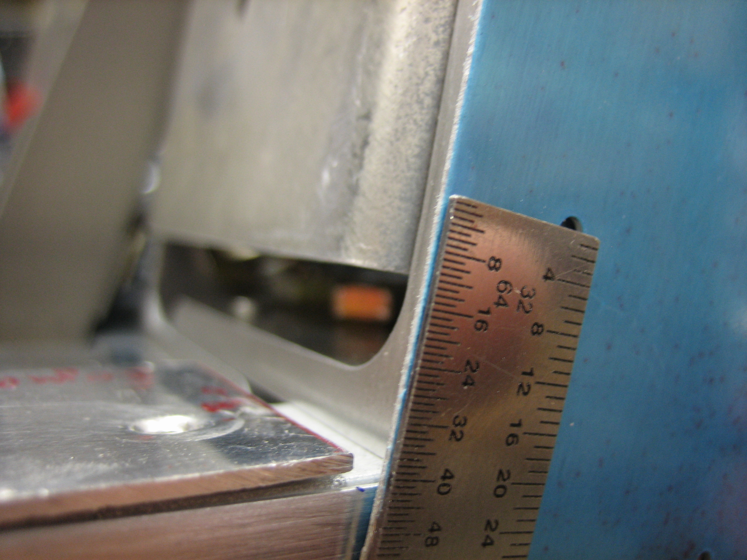
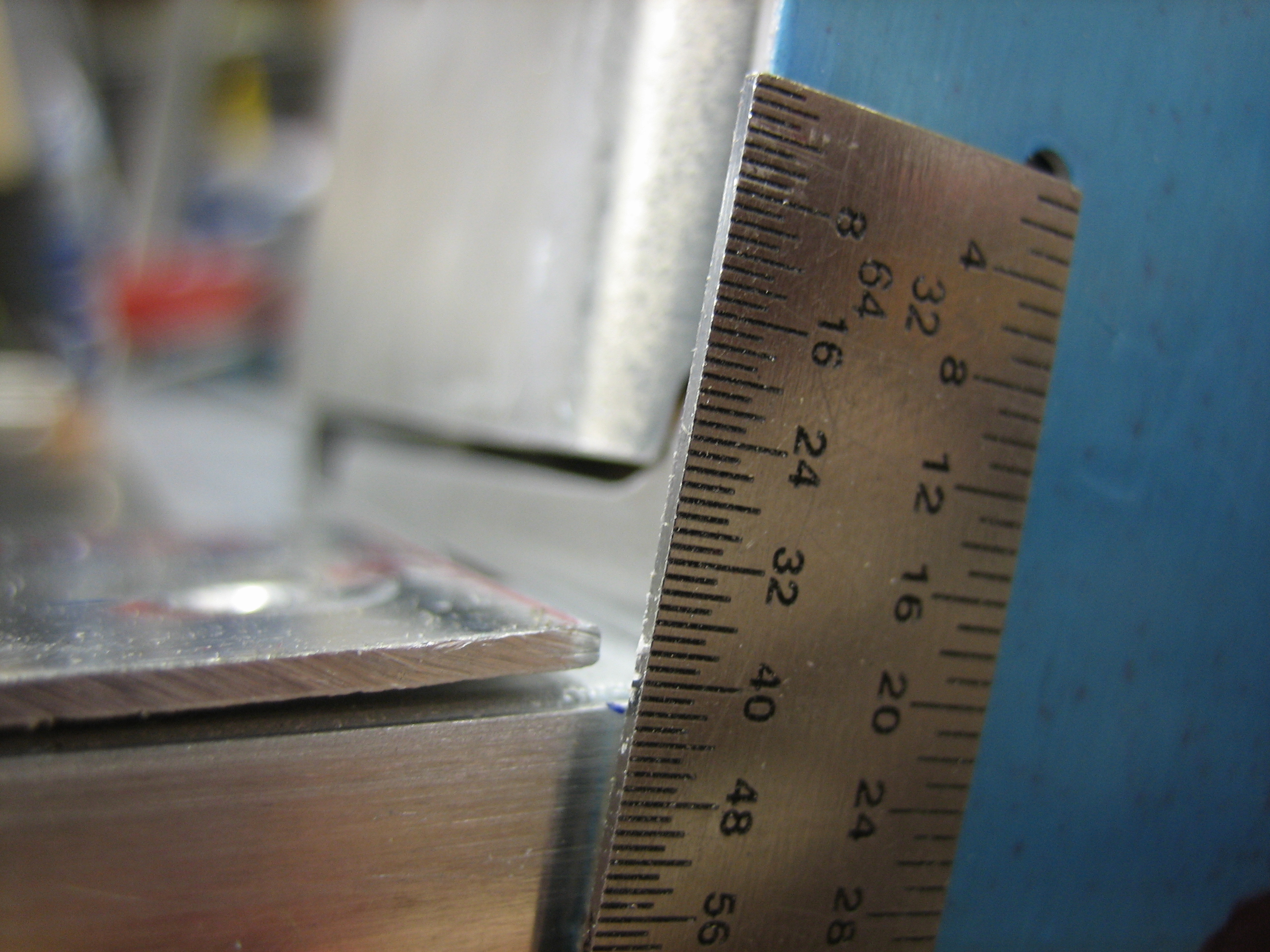
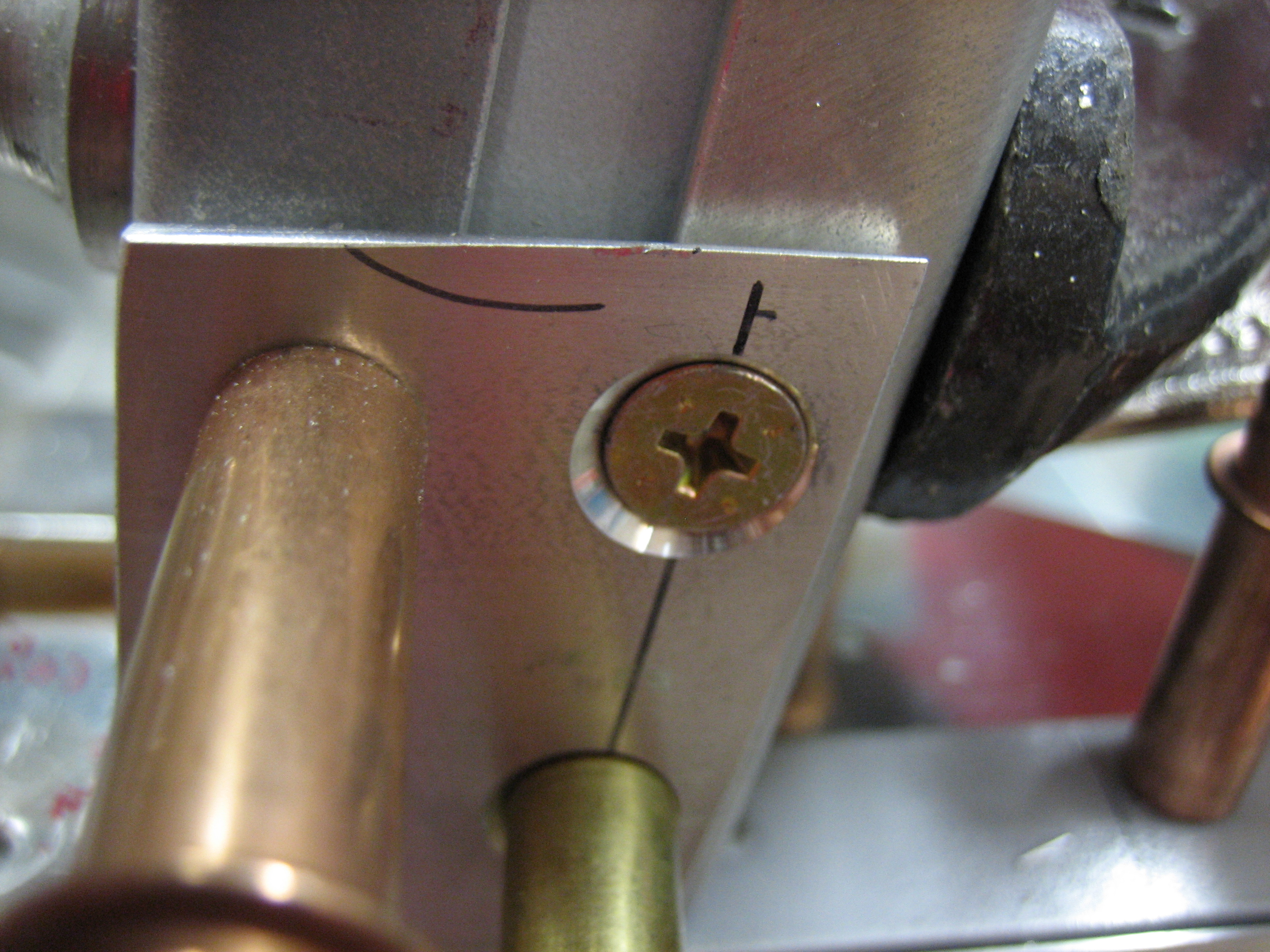
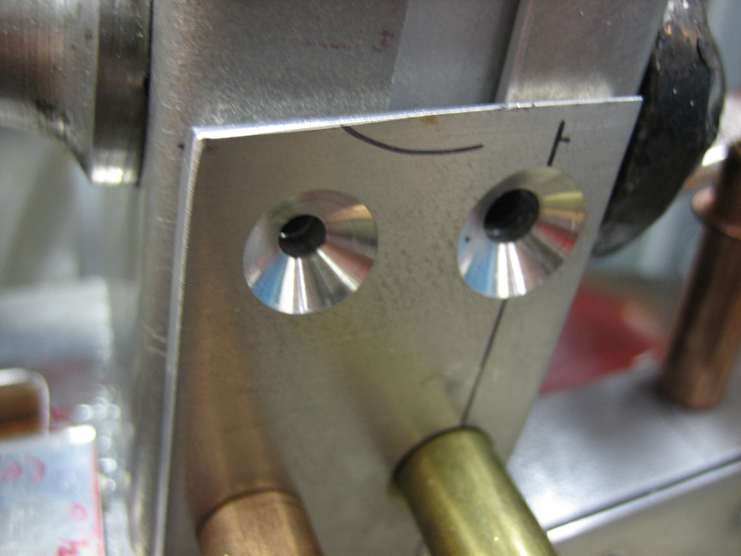
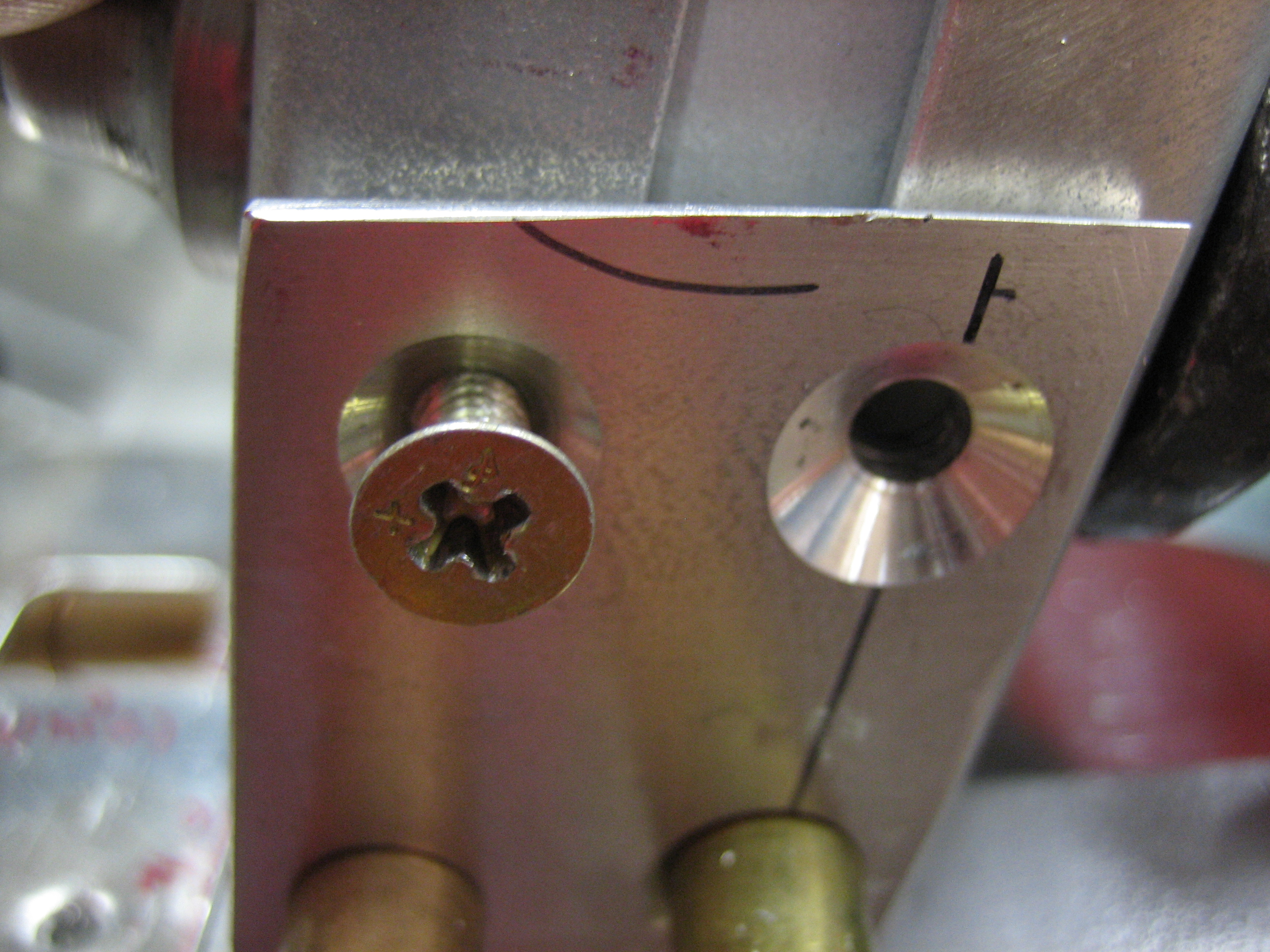
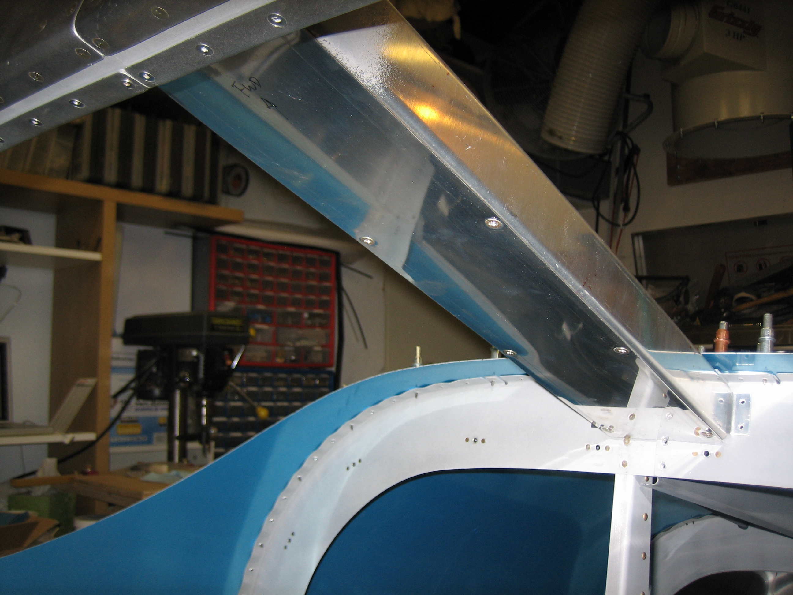
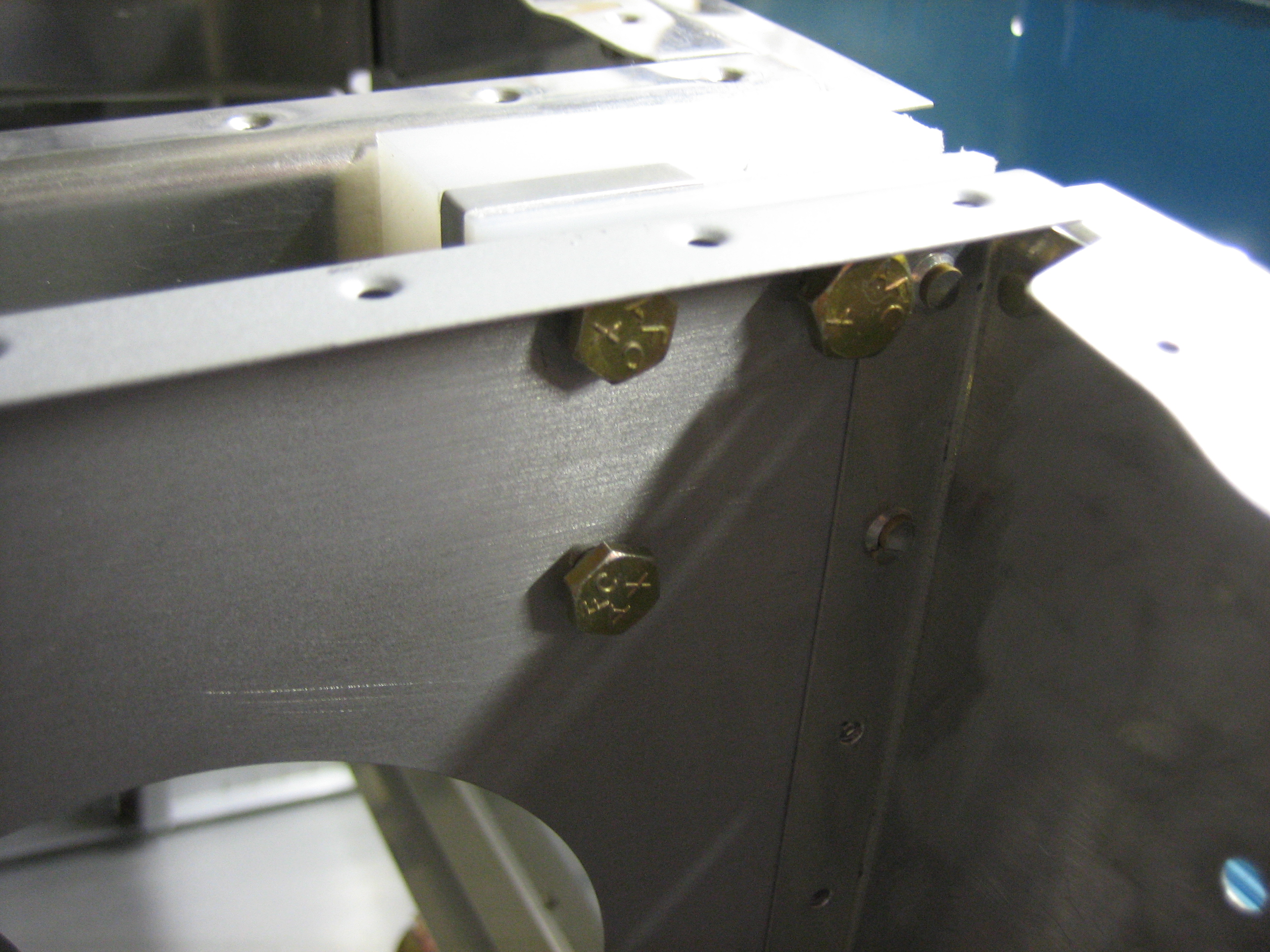
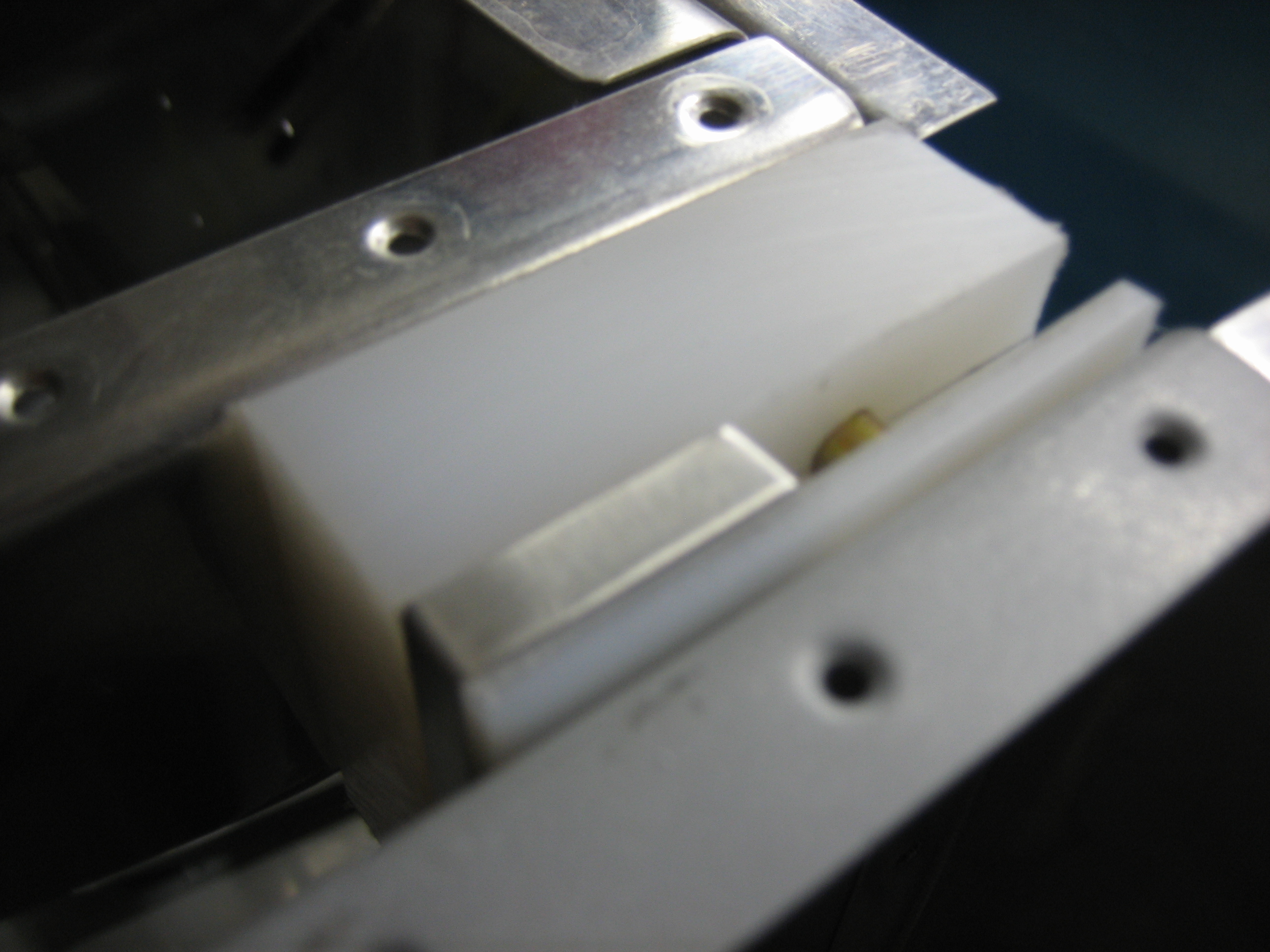
Here’s the cabin frame dropped to the height specified in the plans. There’s now approximately 7/16″ edge distance on this hole which would be more than plenty. I’m probably going to try and move the canopy up to the minimum edge distance for this hole to get as much headroom as possible. A #29 hole is 0.136″ diameter. 1.5D edge distance would require 0.204 edge distance which is just over 3/16″. If I increase that to 1/4″ to get a little more than minimum, then I’ll end up with a cabin frame about 3/16″ above normal.