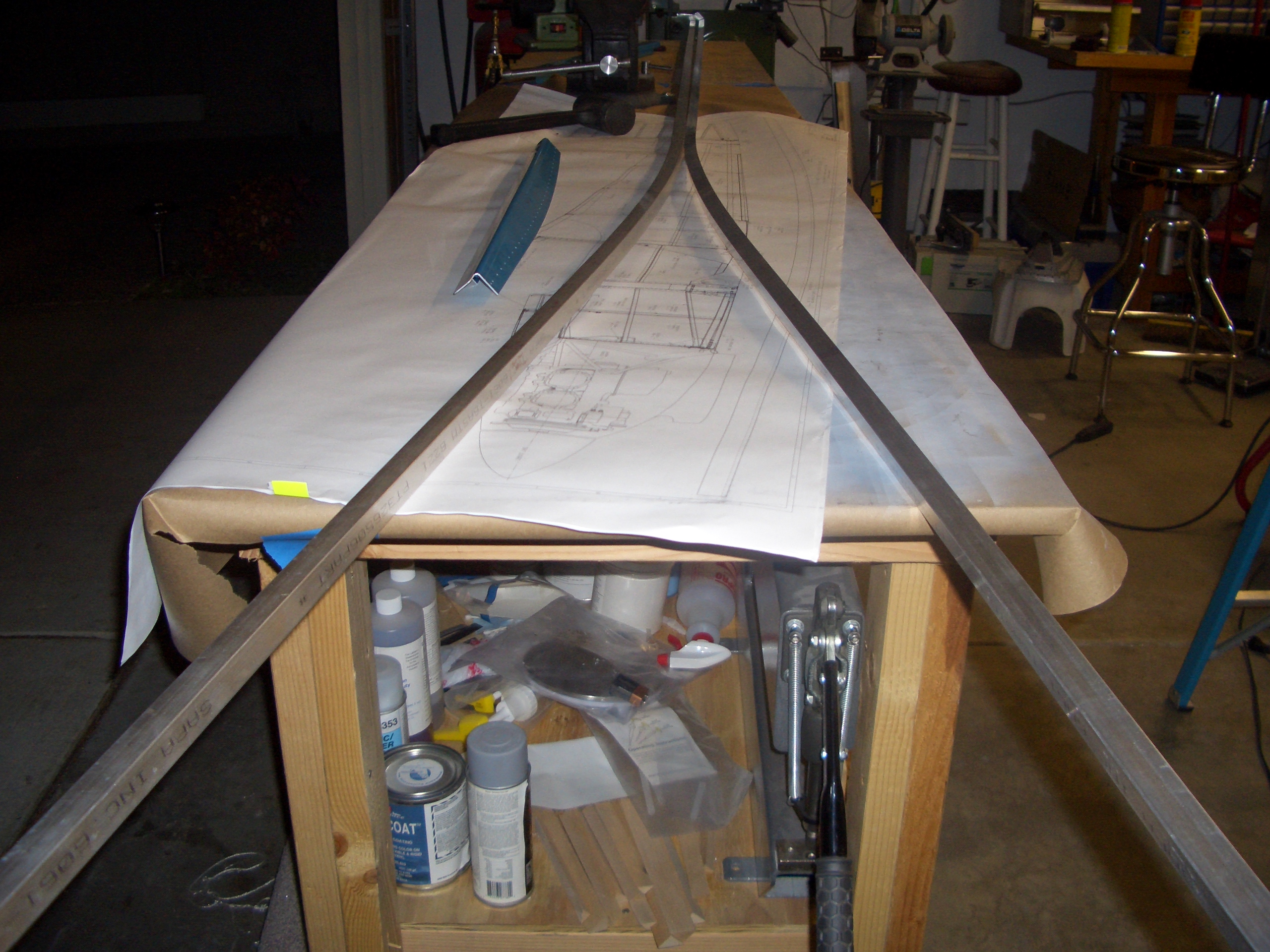
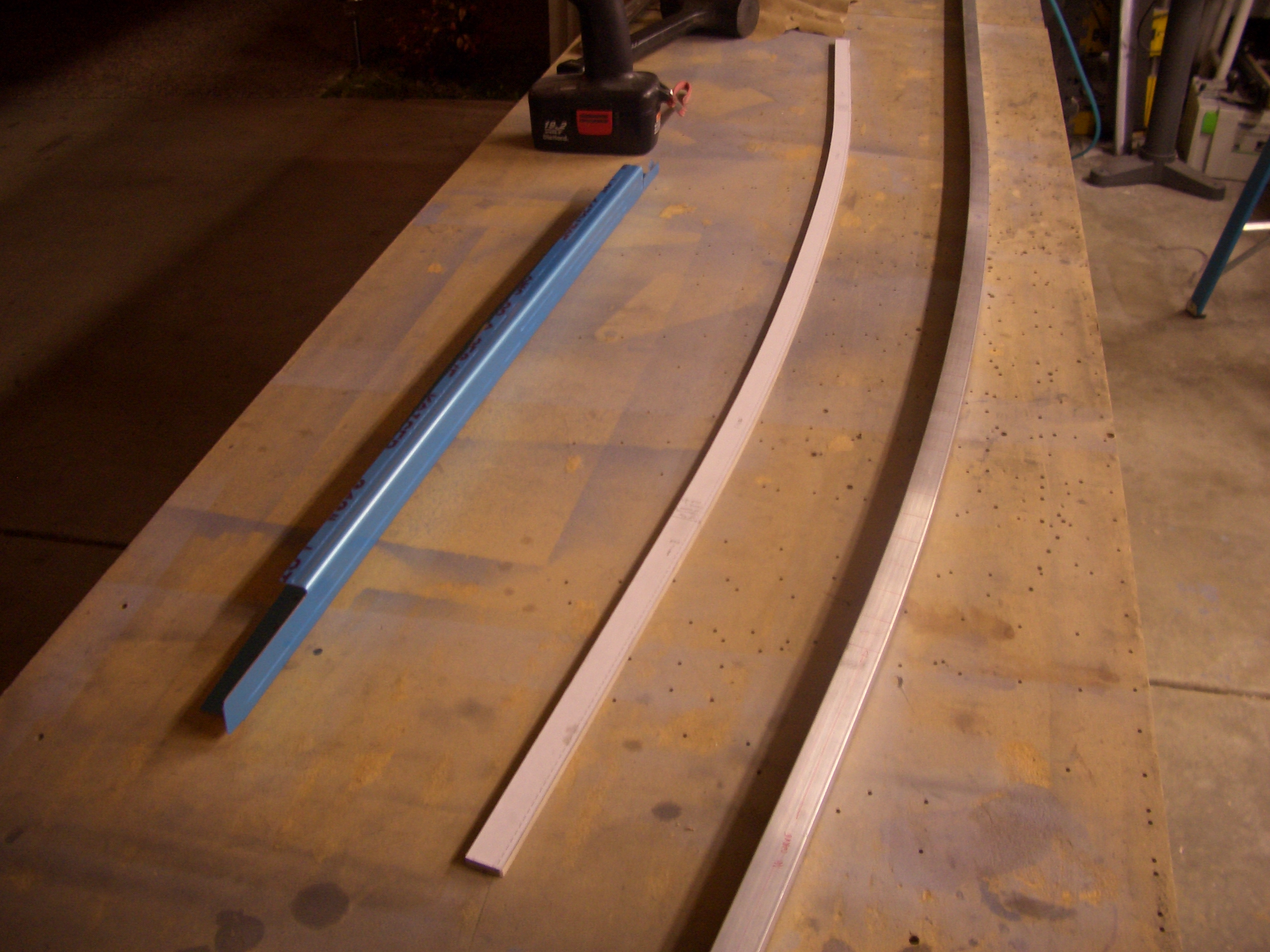
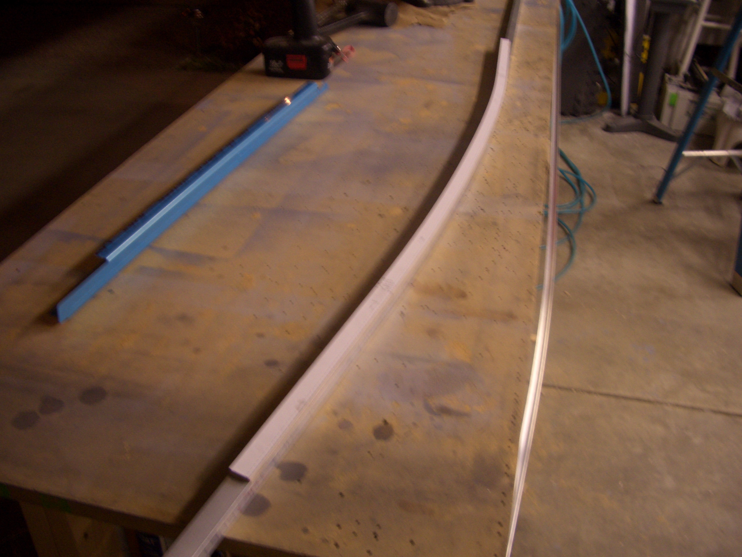
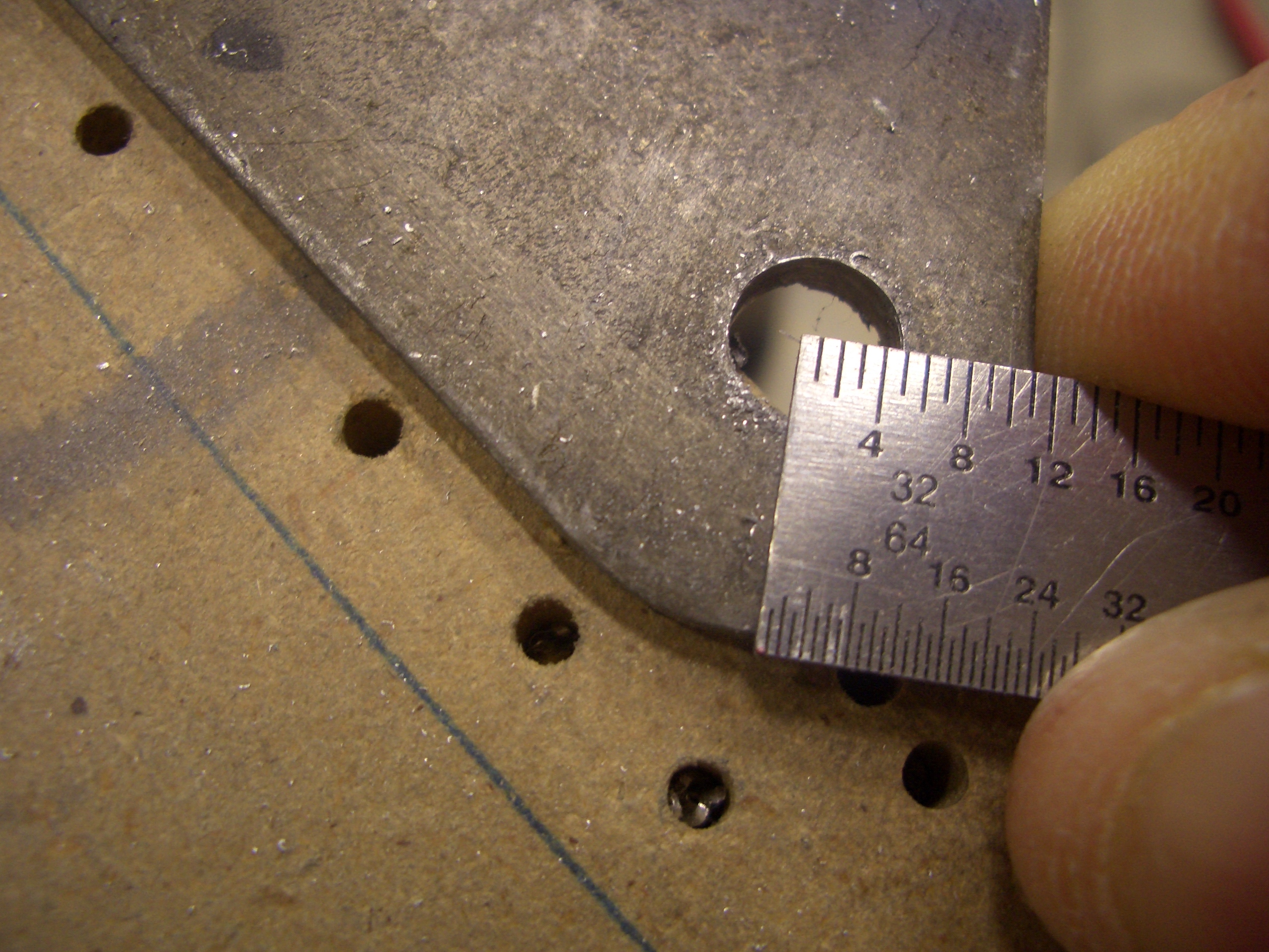
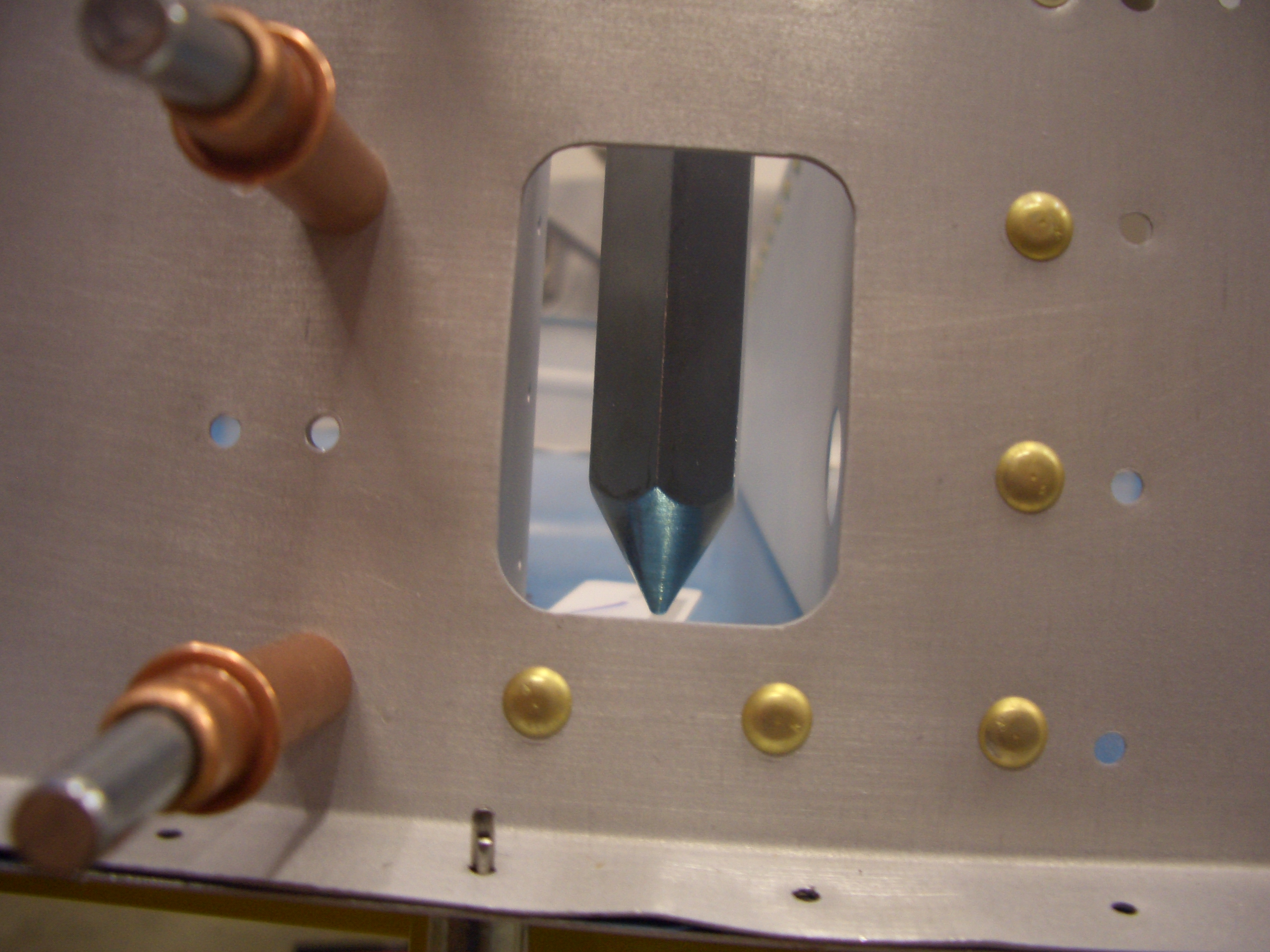
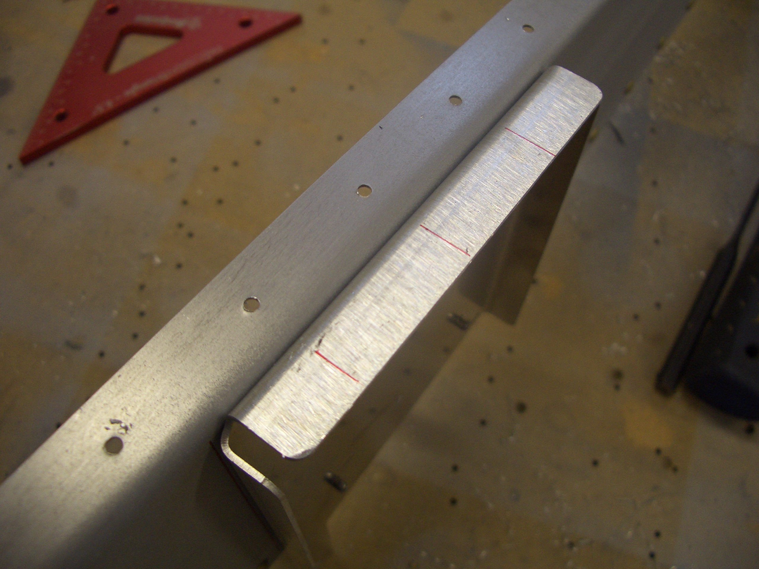
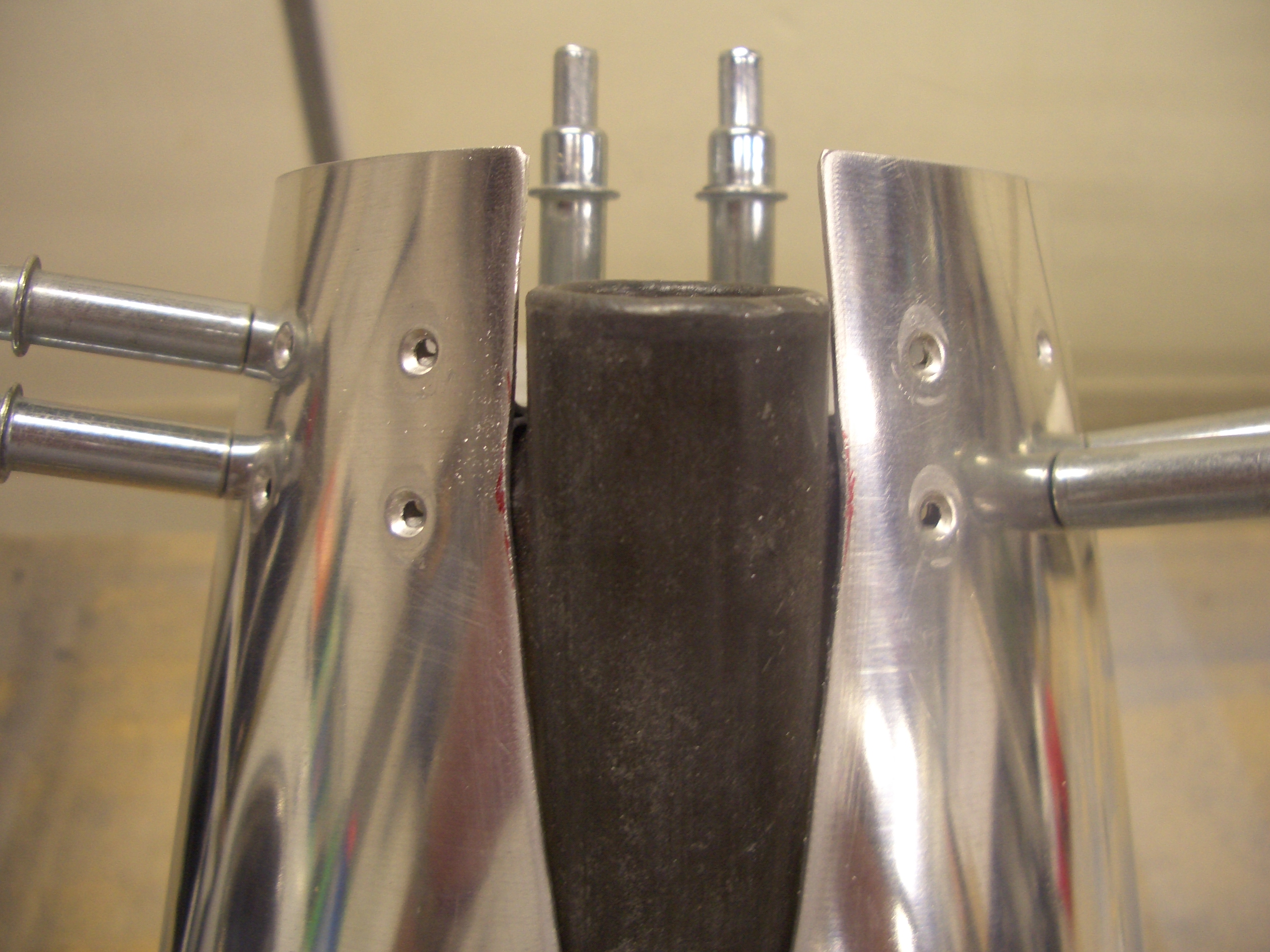
I started bending the longerons tonight. The instructions specify that they be clamped in a vise, bent a little to put some preload, then hit with a rubber mallet to bend it slightly. Move the longeron down an inch or so and repeat. The problem is that any bend you add in one axis creates an inadvertent bend in the other axis as well as a twist. You then need to clamp the other leg of the angle in the vise and remove the inadvertent bend and use a crescent wrench to remove the twist. Unfortunately, that removes some of the intentional bend. It’s a very iterative process. Van’s specifies that the bend needs to be accurate to within 1/16″, but I’m shooting for no more than 1/32″.
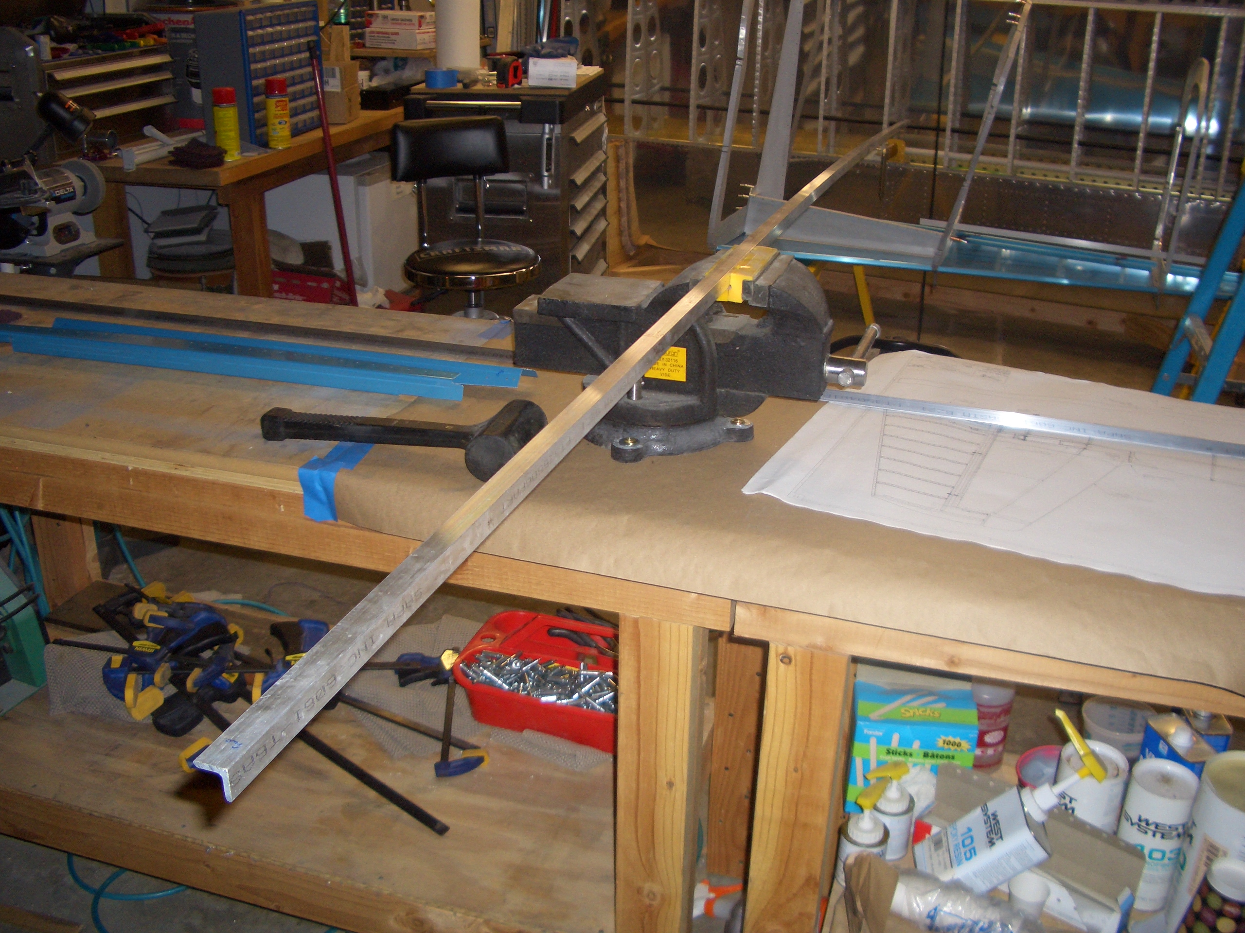
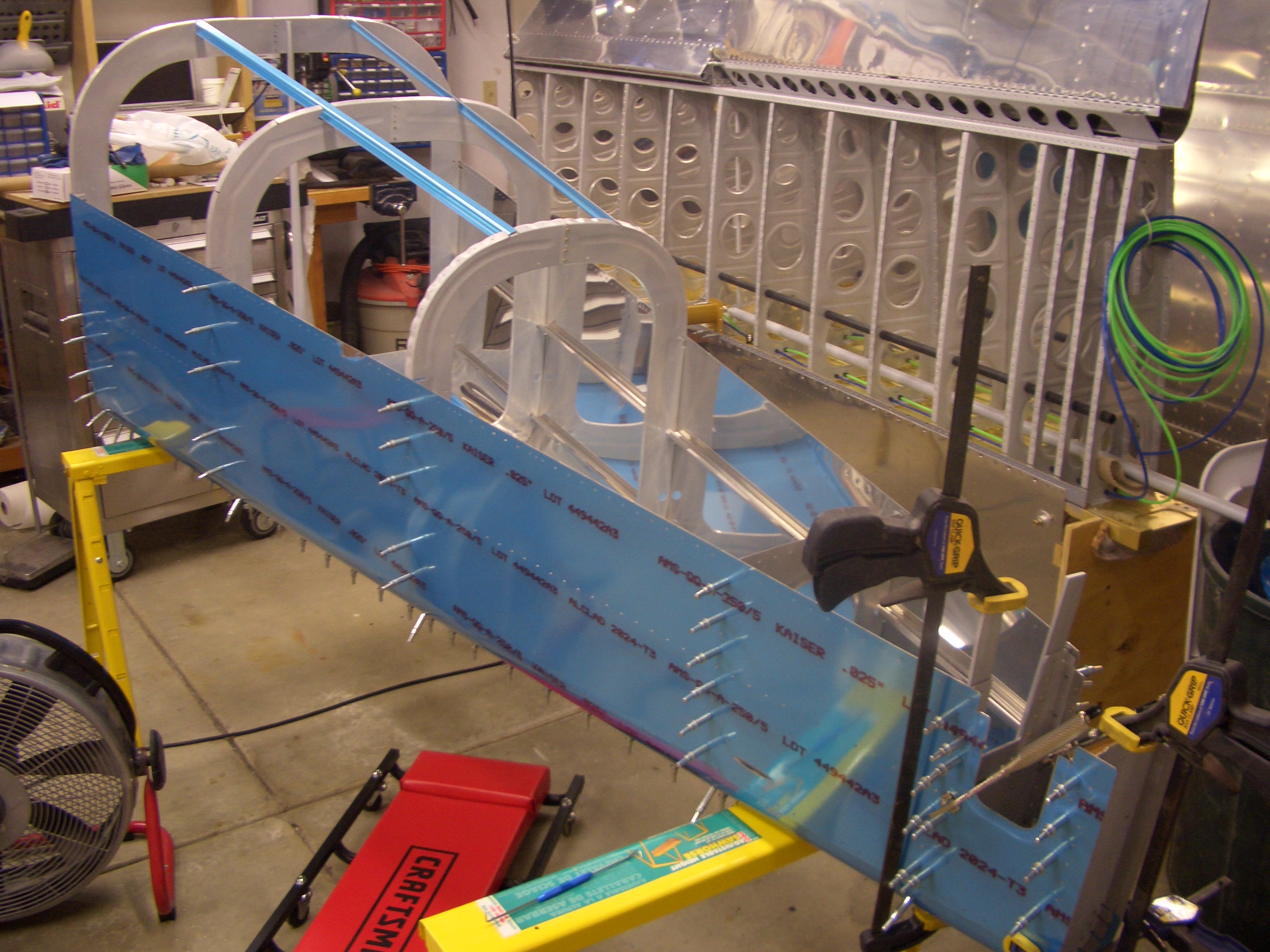
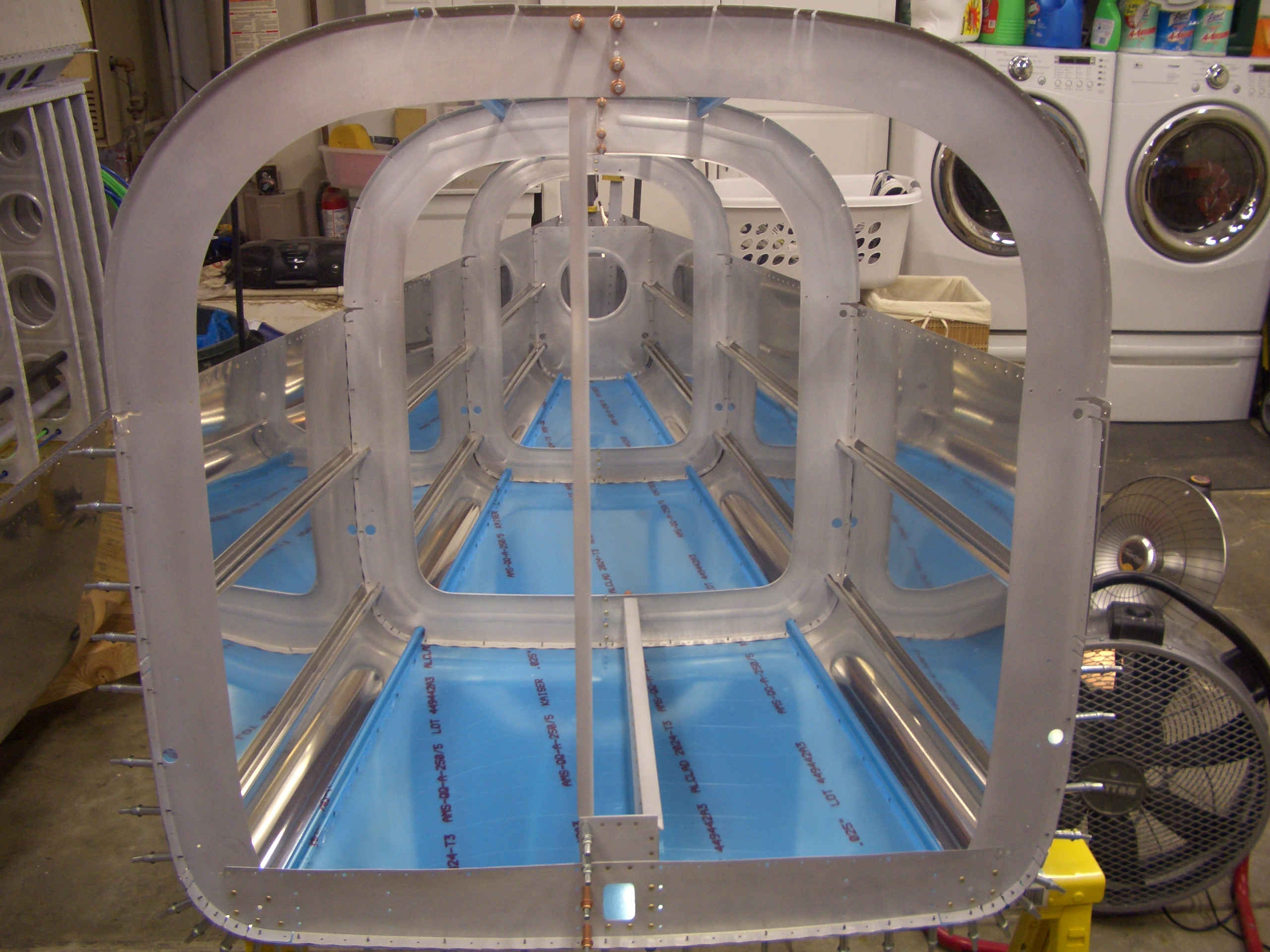
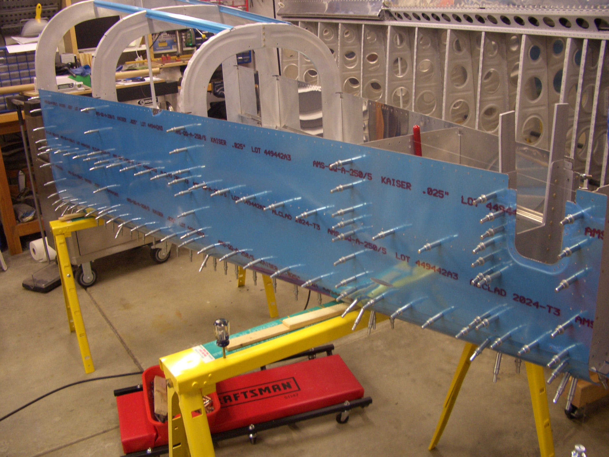
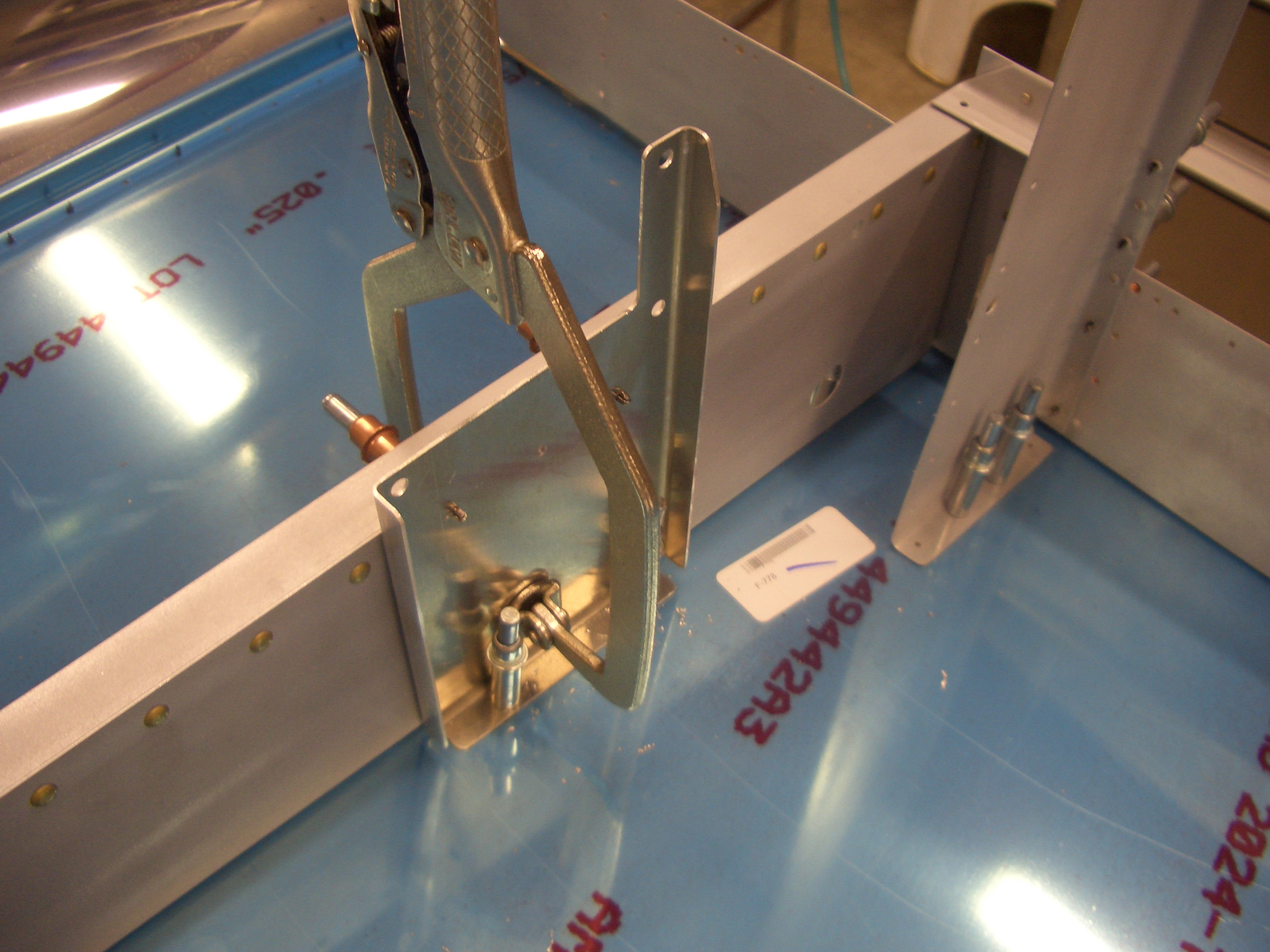
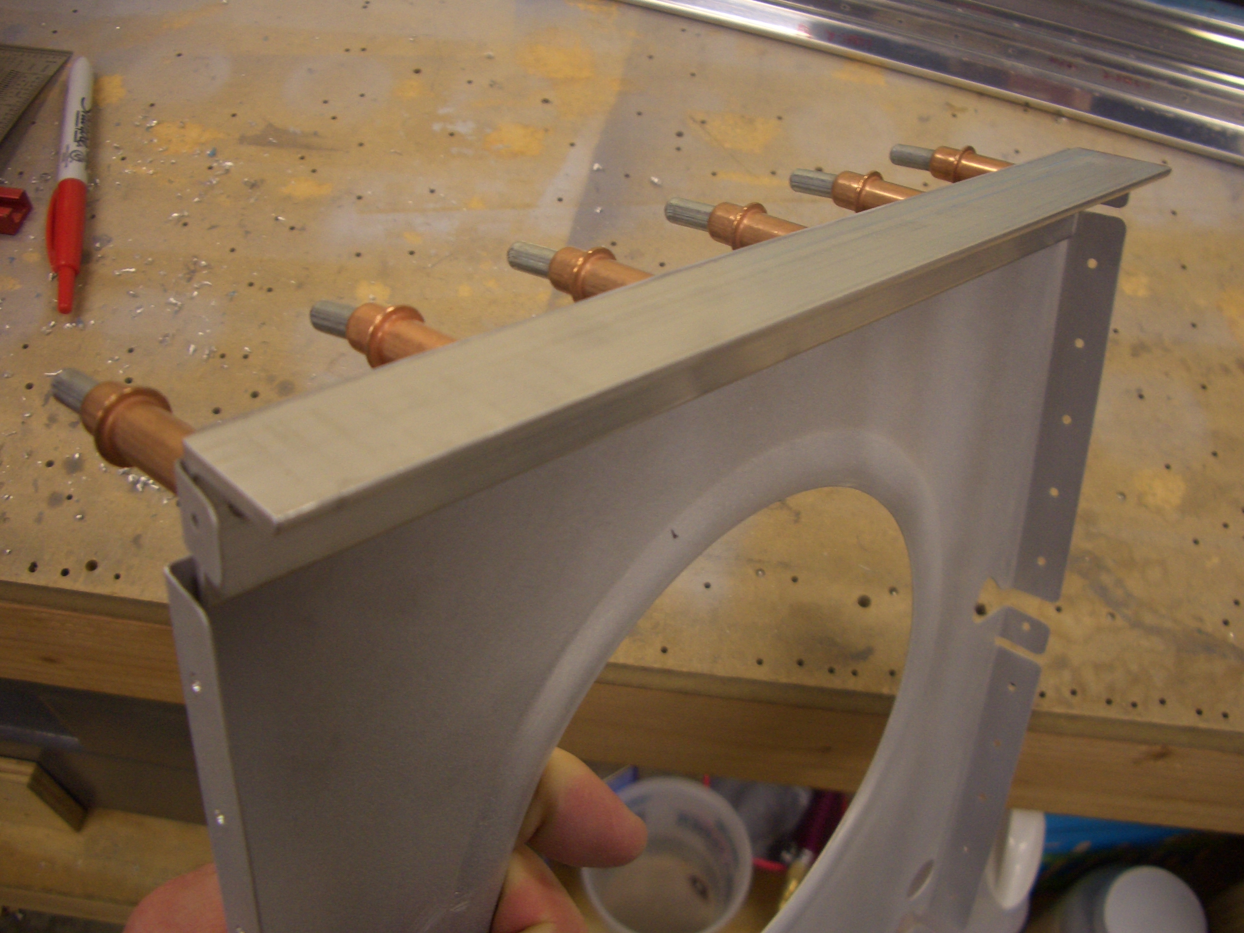
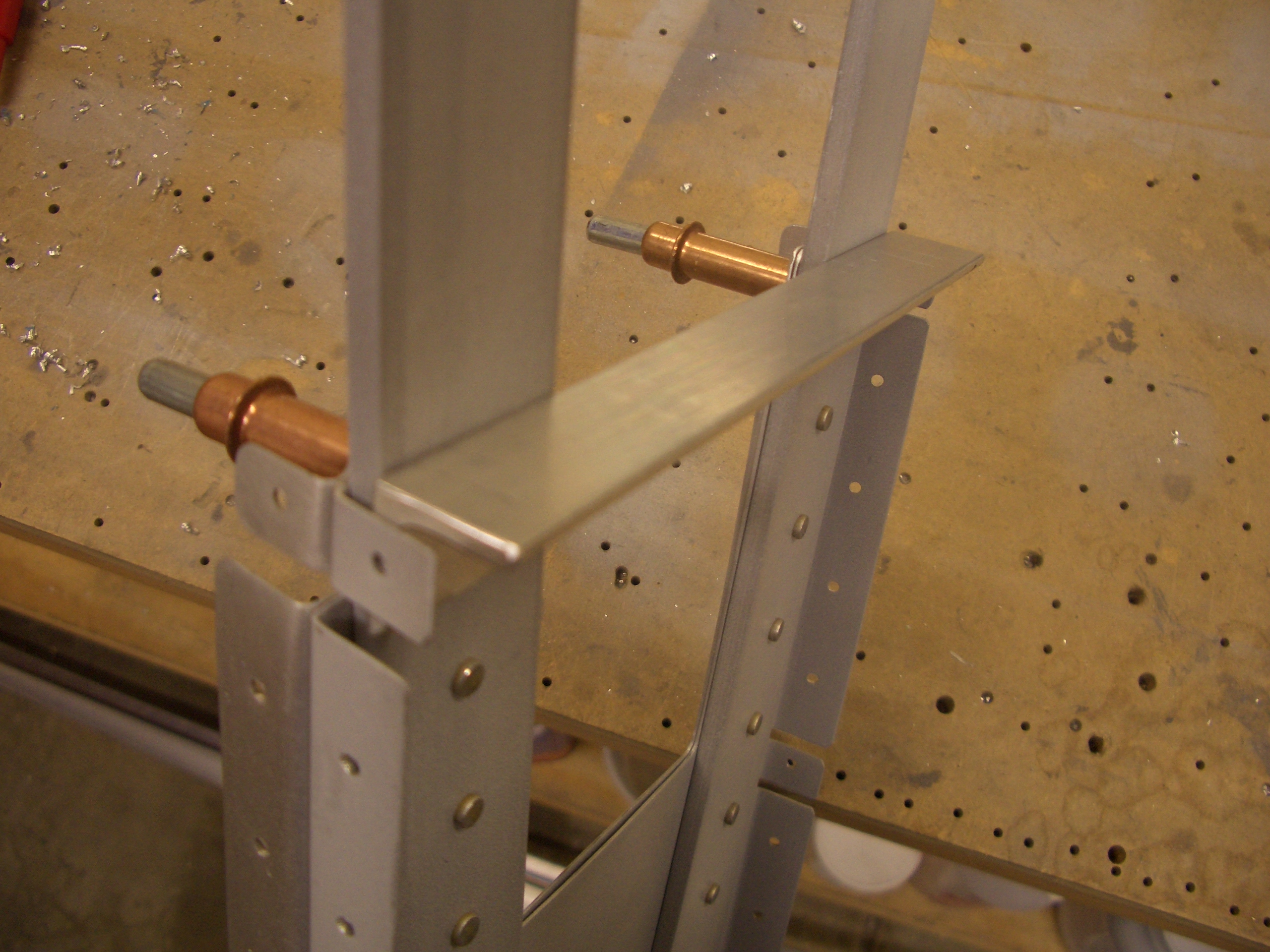
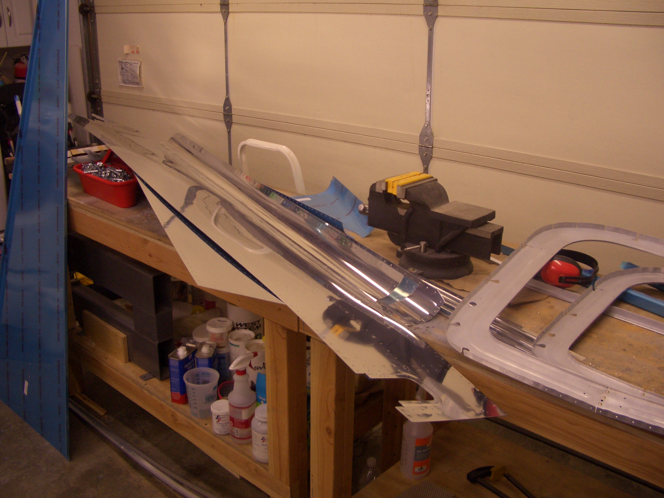
I’ve heard several builders recommend that you spread the bending over a number of small sessions instead of trying to do it all at once since it can be quite frustrating. I spent about 30 minutes tonight getting an initial bend into each of the longerons. This is within an inch or so of the template, so there is a lot more tweaking to do, but it’s a start.