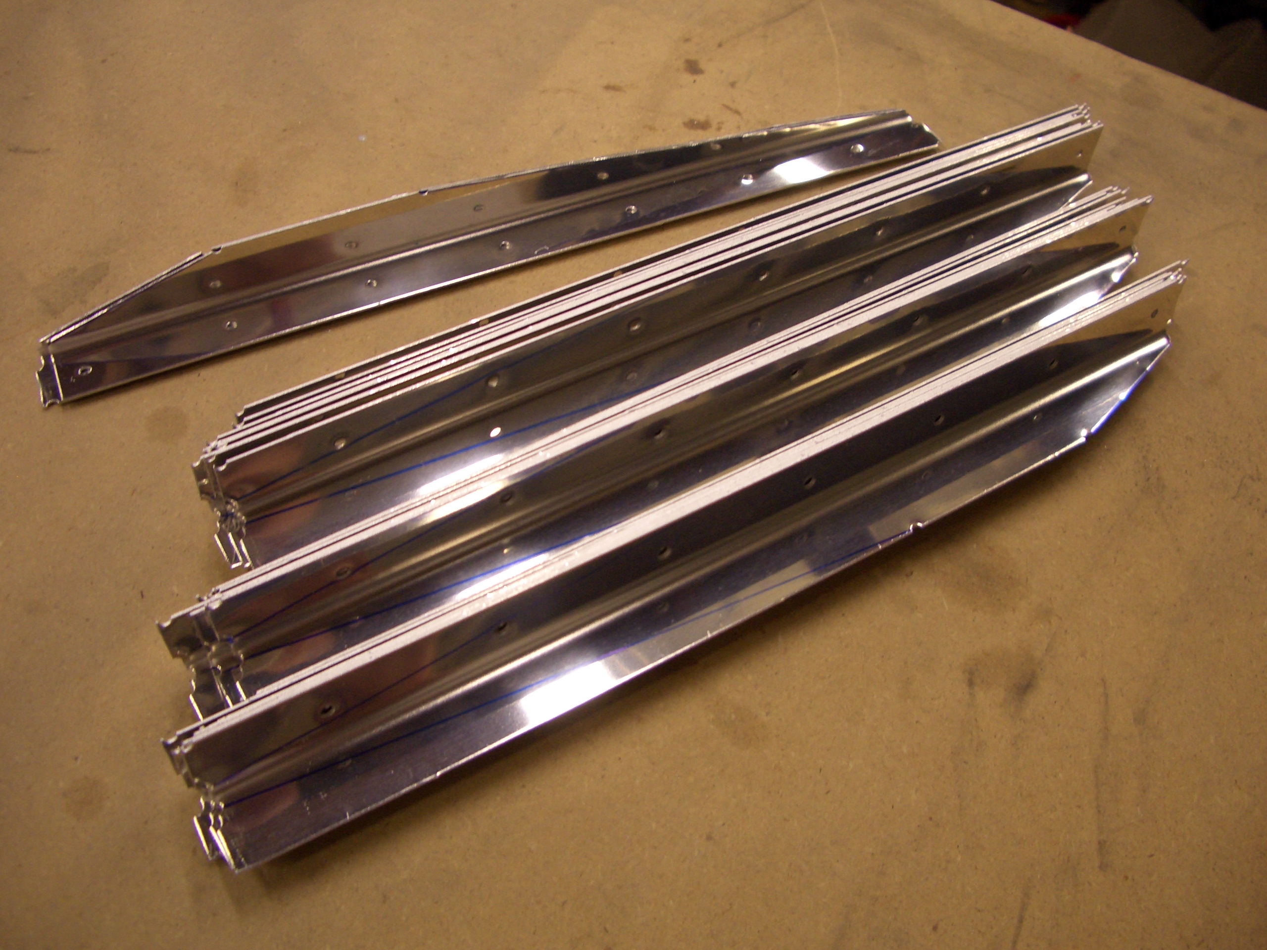
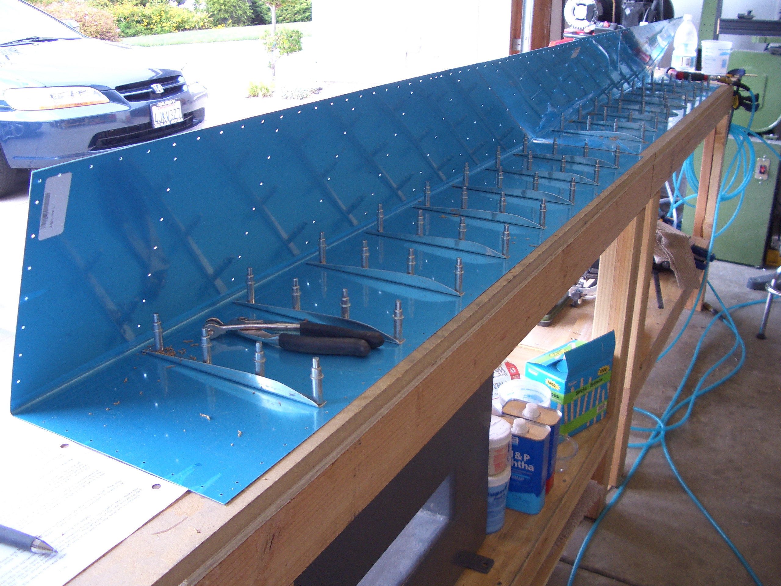
I prepped the other three top main wing skins today. Since the top skins are the only ones that will be attached soon, that’s all I’m going to do for right now. It will be good to take a break on these and work on something else for a bit.
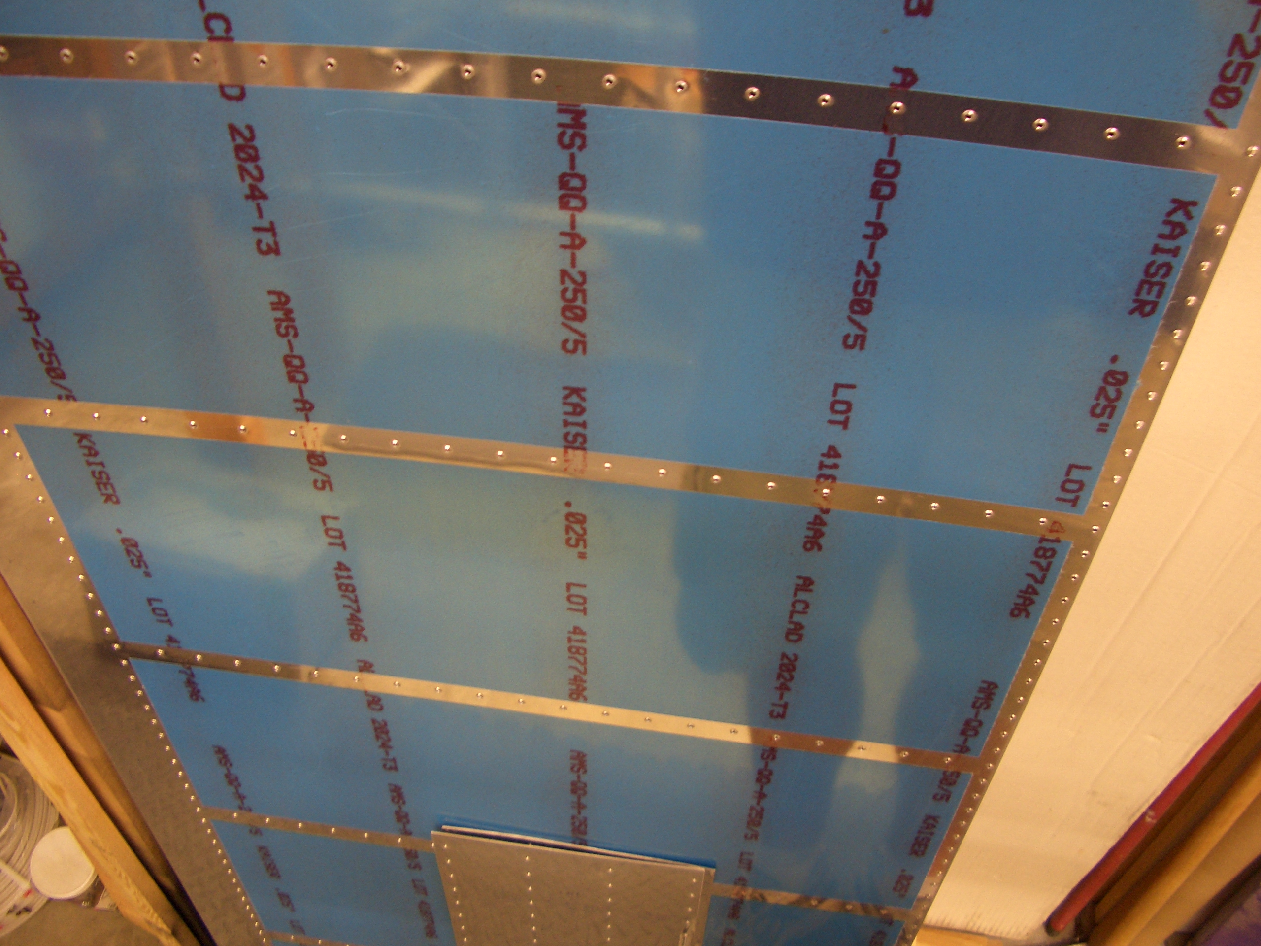

I prepped the other three top main wing skins today. Since the top skins are the only ones that will be attached soon, that’s all I’m going to do for right now. It will be good to take a break on these and work on something else for a bit.
After reevaluating the shims I had made, I decided that using shims that varied in thickness was the wrong approach. The ribs already define the correct wing curvature, so shims that vary in thickness would just create ripples in the skin. The problem is really that the splice plate is too low and the variation I measured was due to the tank skin getting pulled tighter where the screws attach and pillowing out between them. Instead, the entire splice plate needed to be shimmed out a small amount. Looking at the measurements I made previously, I determined that shimming the splice plates out 0.016″ and shimming the skins out a further 0.008″ would be about right.
I fabricated the new set of shims using some 0.008″ aluminum flashing purchased from the aviation isle at Home Depot. Two will fit between the inboard rib and the splice plate and one will fit between the splice plate and the skin (the outboard skin is 0.024″ and the tank skin is 0.032″, so this should bring the skins flush).
I ordered the fuselage kit today. As I’ve mentioned before, I’m going with the tailwheel configuration with tip-up canopy. I recently had a chance to fly in Kevin Hester’s RV-7A (thanks Kevin!). He has an A model (nosewheel) and a slider canopy, so pretty much exactly the opposite configuration as I’m going with. The slider has a roll-bar in front of you which blocks part of your view. Although I didn’t find this objectionable, I was so blown away with the unobstructed visibility in the factory RV-7 that I really wouldn’t even consider building a slider.
I also added the electric aileron trim option since I like gadgetry.
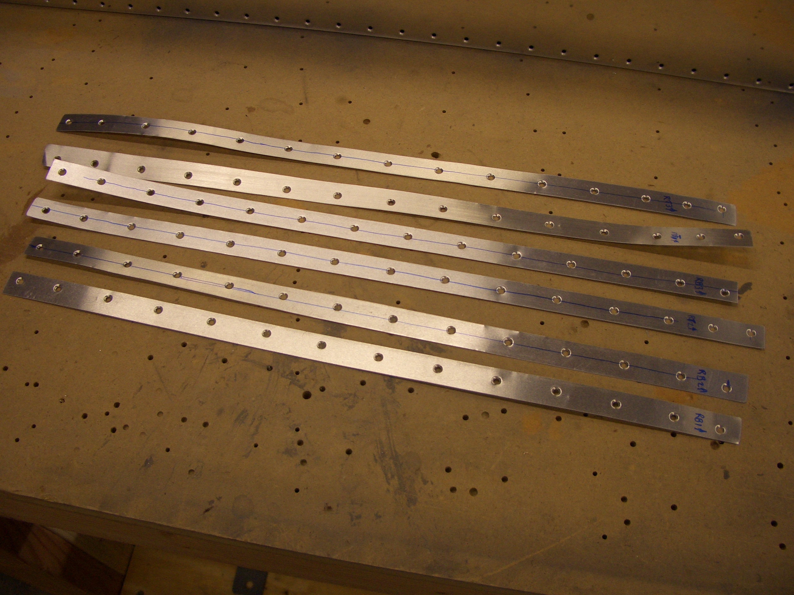
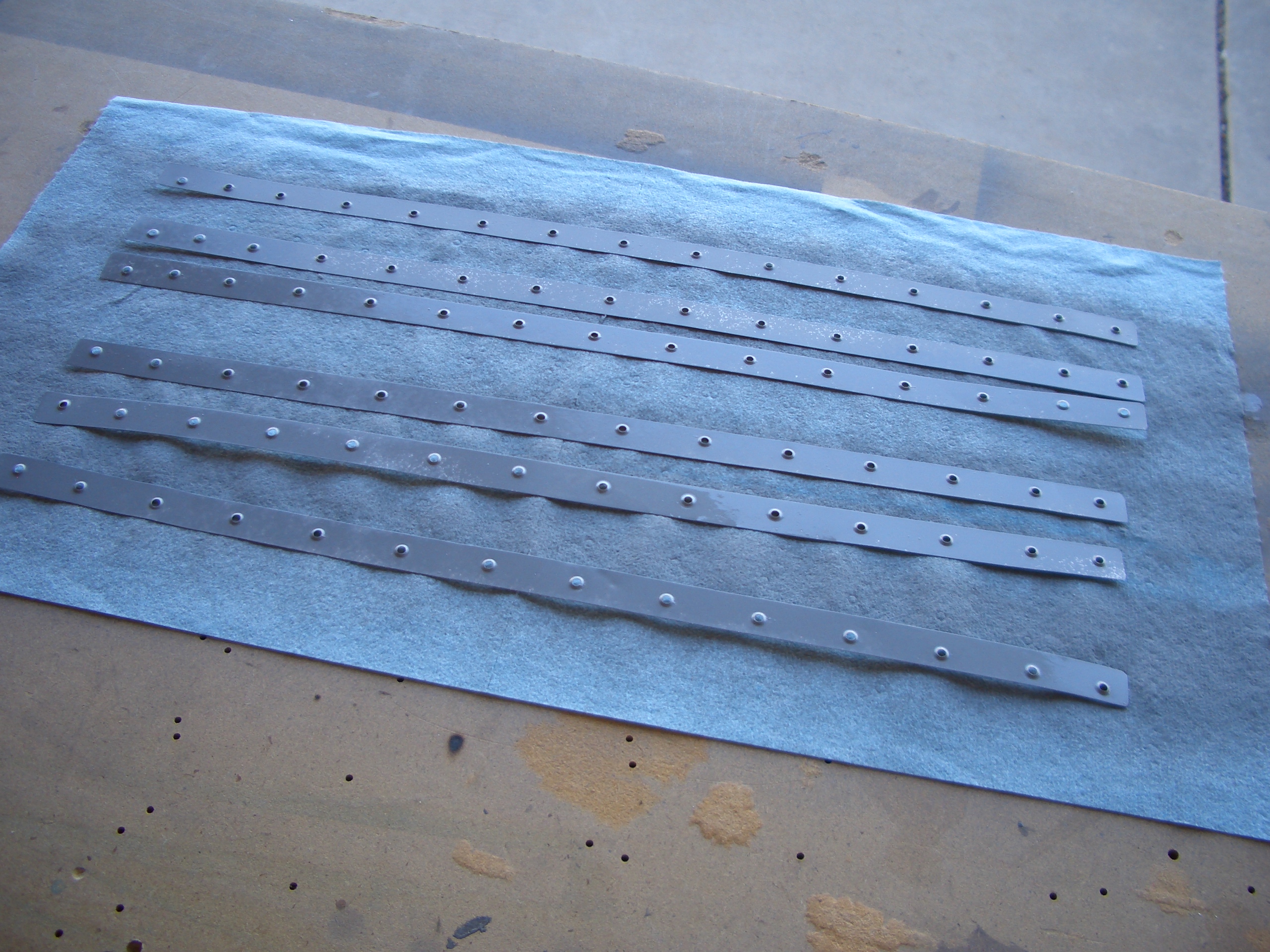
My wife is leaving town for a few days, so I wanted to get the leading edge riveted back together before she left. In preparation, I went out this morning before work and drilled, dimpled and primed the shims.
I clecoed everything together, but it’s too late to rivet this tonight. We’ll knock this out tomorrow morning before she leaves.
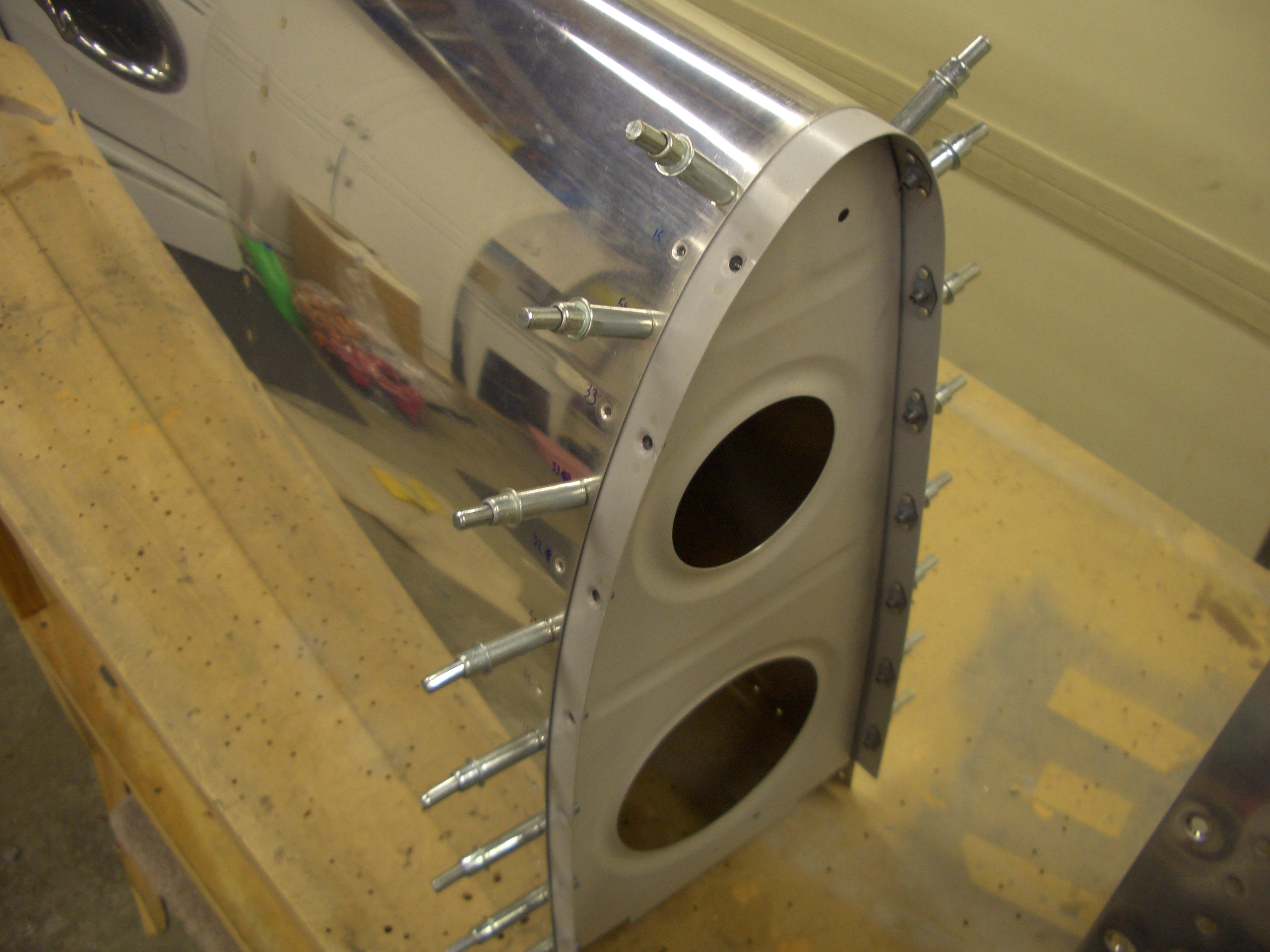
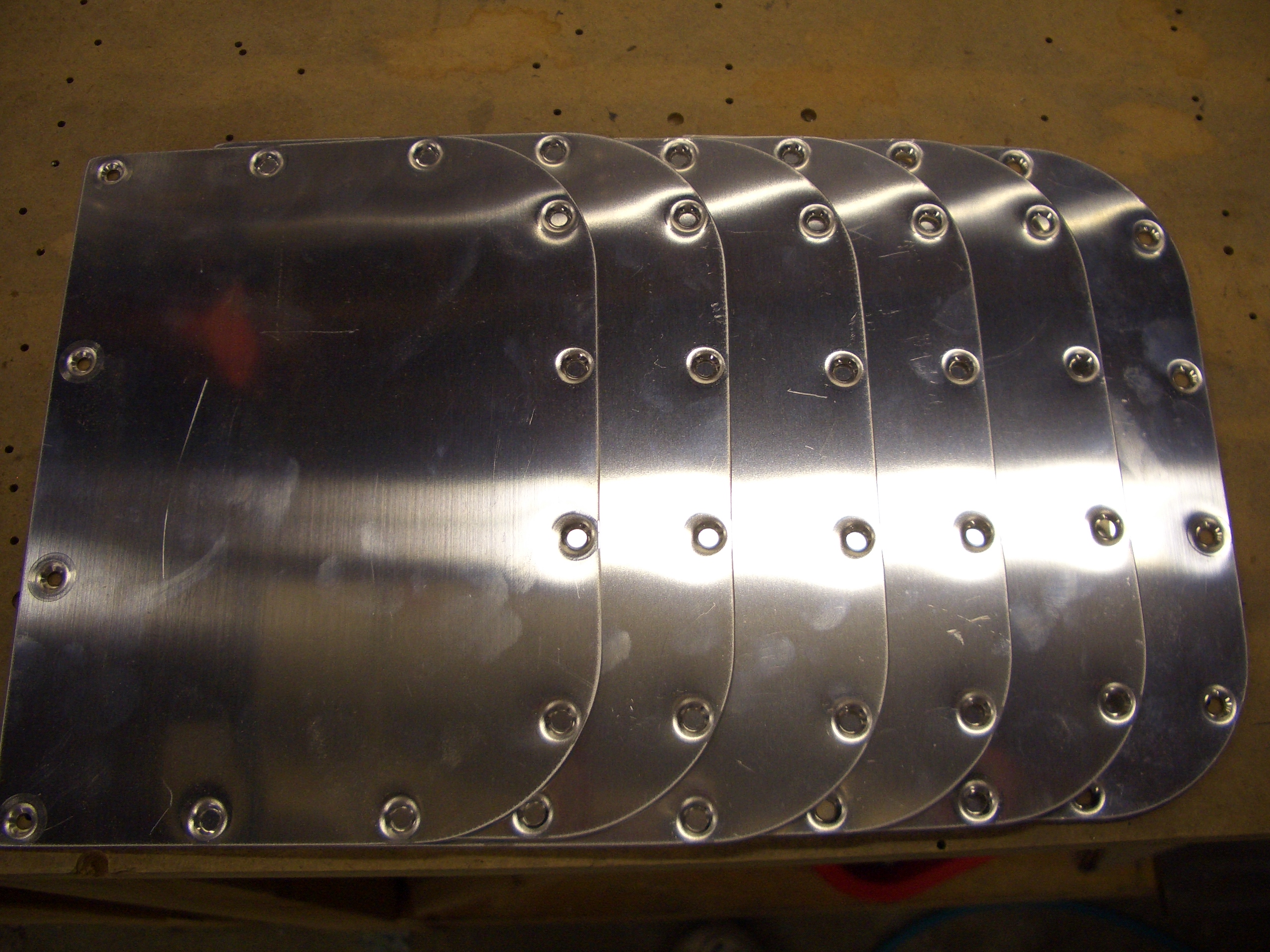
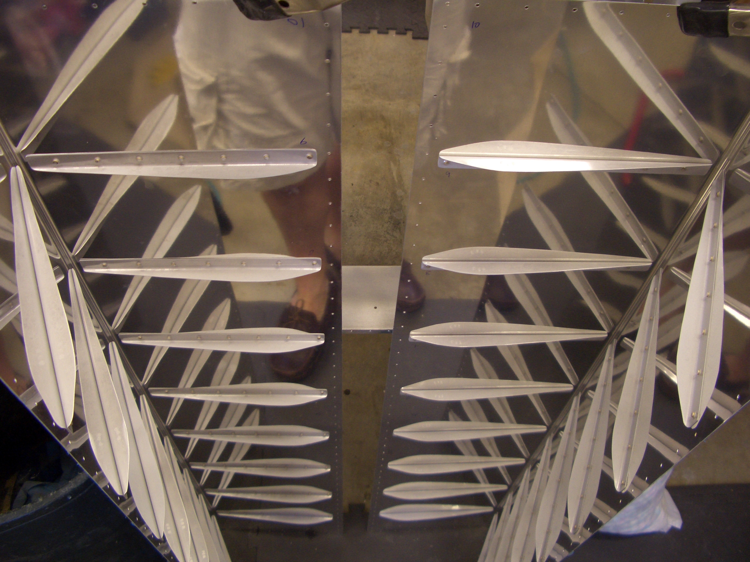
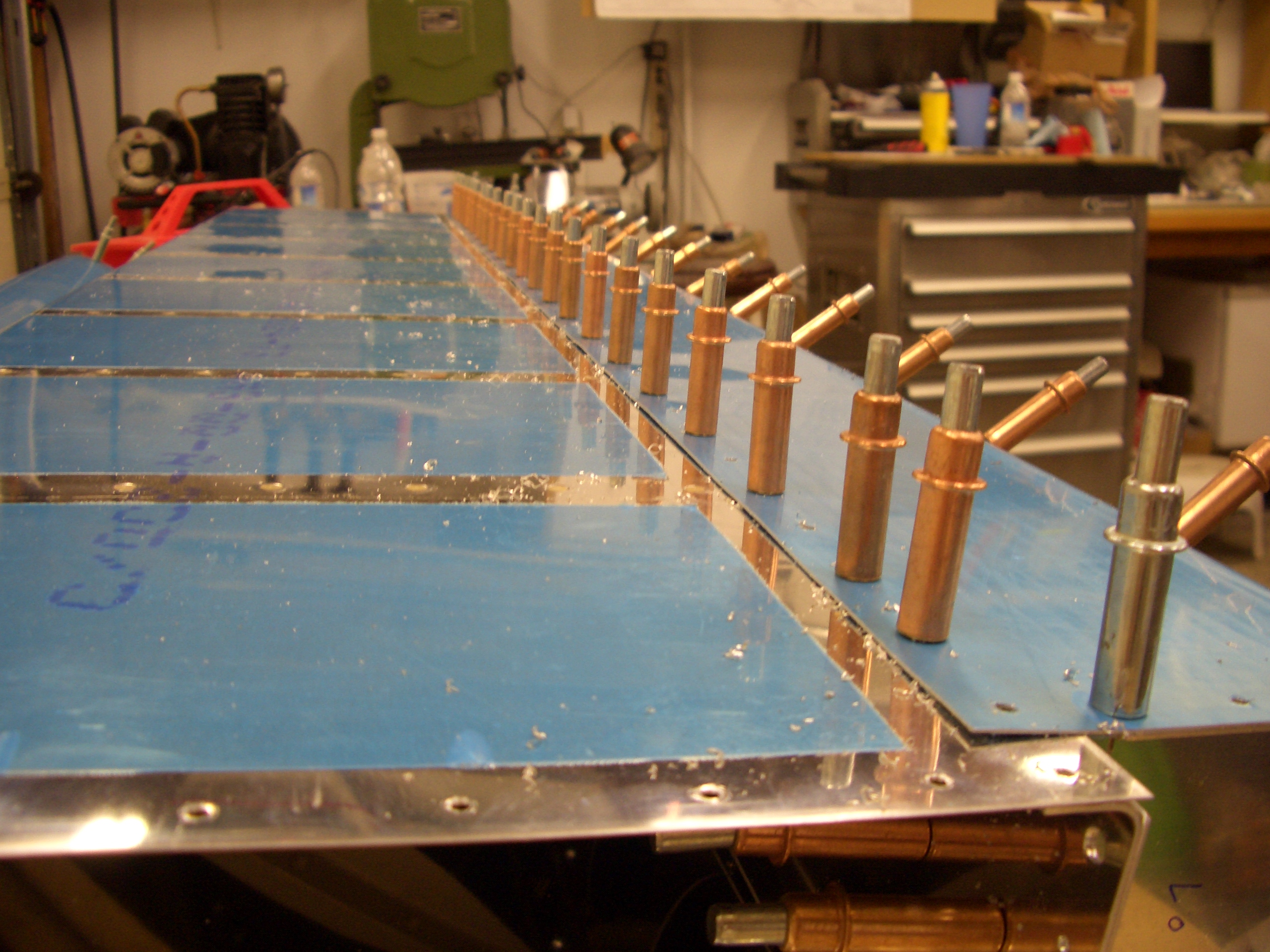
Since I couldn’t move forward on the leading edges, I went ahead and drilled and dimpled the wing access plates. The holes along the straight edge are drilled and dimpled for #6 screws and the rest are drilled and dimpled for #8 screws.
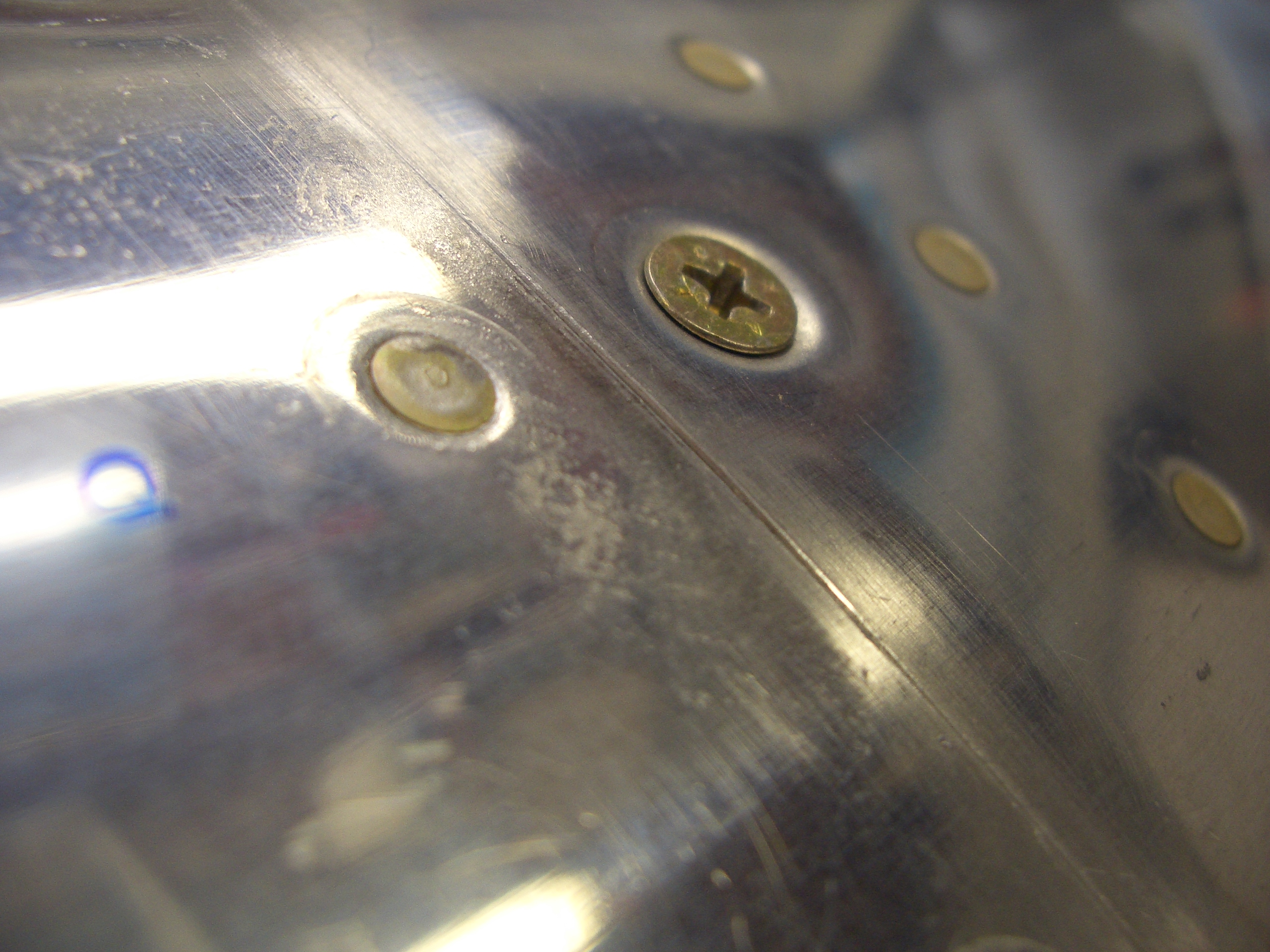
Before leaving town, Jenn helped me rivet the splice plate back onto the left wing. This side looked even better than the other. Right after initial fitting, the joint in basically perfectly flush along almost the entire length. I have to do a little adjustment in a couple of spots, but it should be relatively minor. This blurry picture really doesn’t capture how nice this looks.
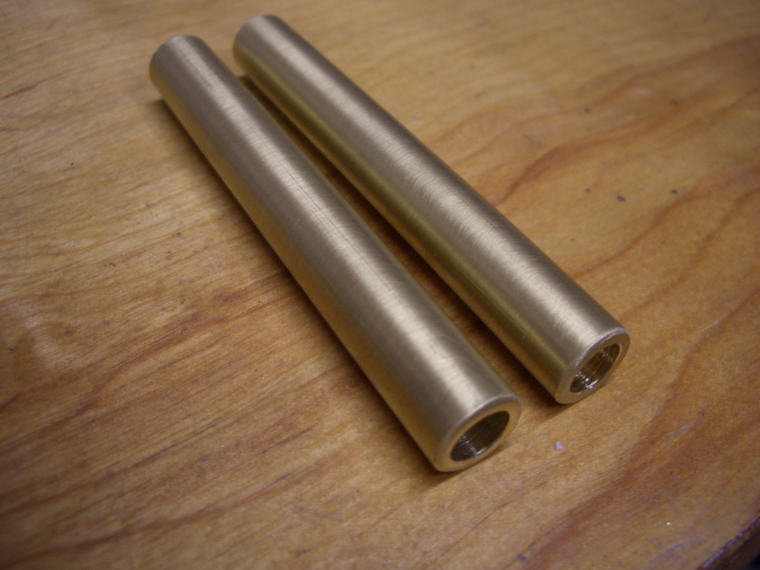
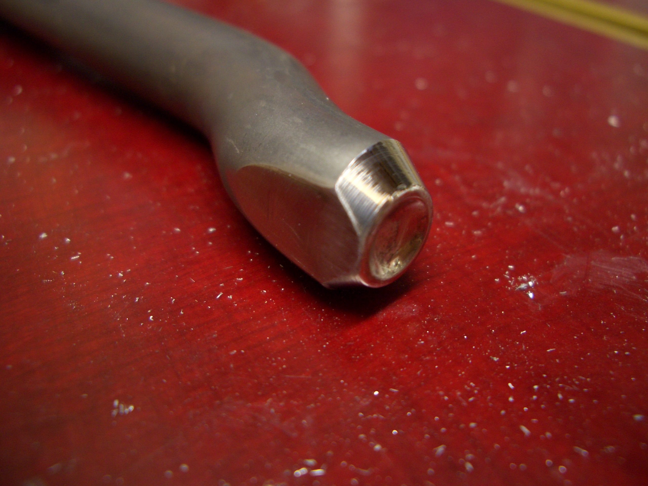
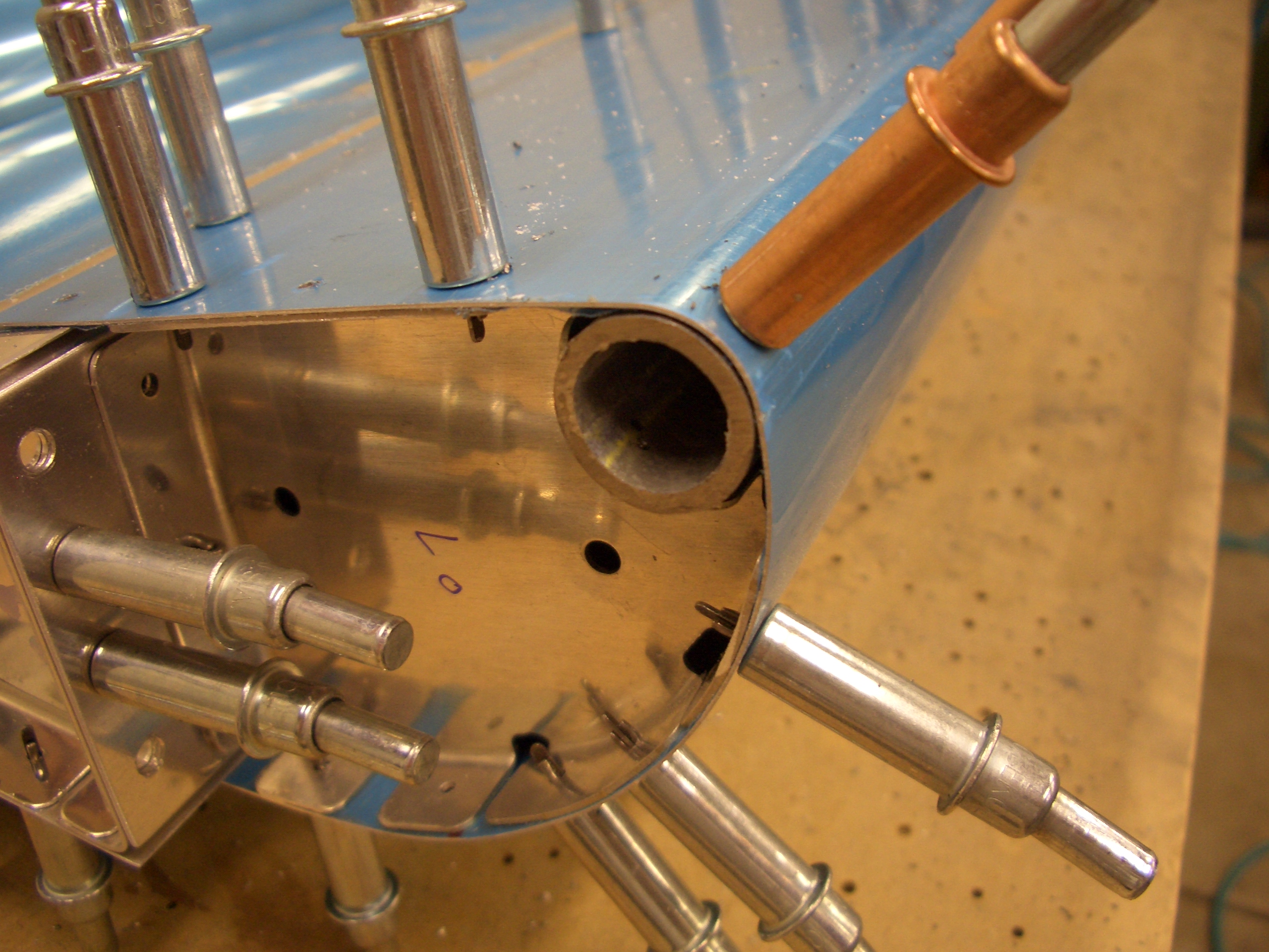
I’m ready to rivet the leading edges on, but since I don’t have a riveting partner right now, I got started on a few other tasks that need to happen on the wings. I got started fabricating the aileron bellcrank bushings. These are brass tubes that have to be reamed out to 1/4″ for an AN4 bolt and trimmed to a very precise length (basically about 0.015″ to 0.030″ longer than the bellcrank). I did this by chucking them into my drill press and pressing them down onto a file. This slowly filed off the ends until they were the correct length. I also polished the outside with a scotchbrite pad while I had them running on the drill press.
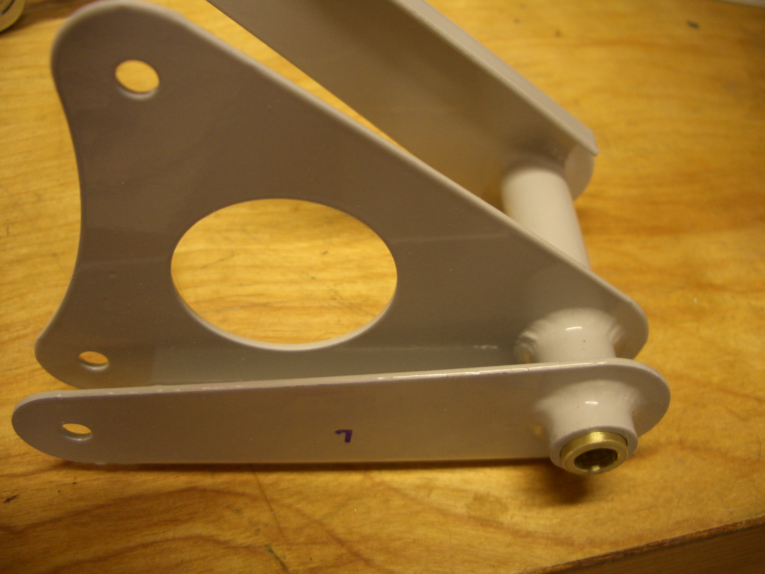
Here is how the bushing fits in the bellcrank. The bushing is clamped between two brackets mounted to the spar and doesn’t rotate. The bearing surface is between the outside of the bushing and the inside of the tube on the bellcrank. A layer of grease keeps everything moving smoothly. The bushing has to be slightly longer than the bellcrank tube to prevent the brackets from causing the bellcrank to bind.
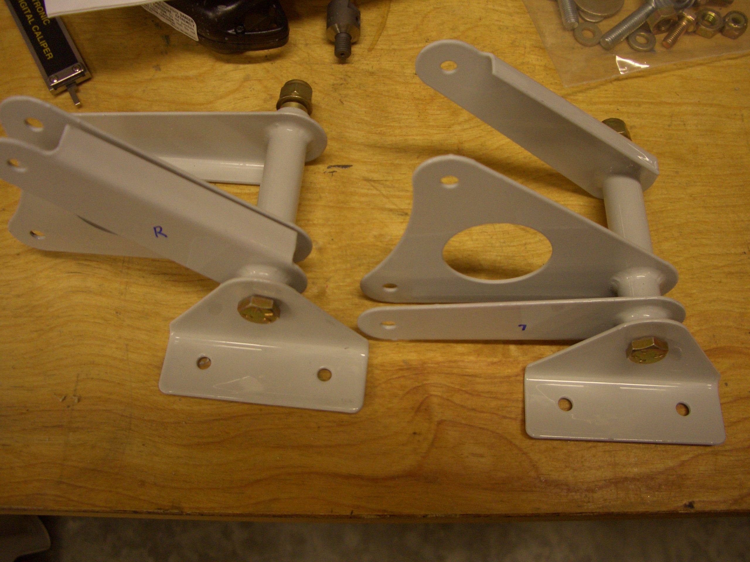
Here are two of the brackets loosely bolted to the bellcranks. These can’t be permanently installed yet because I don’t have the appropriate grease to install these with. The other brackets are already installed on the wing and torqued.
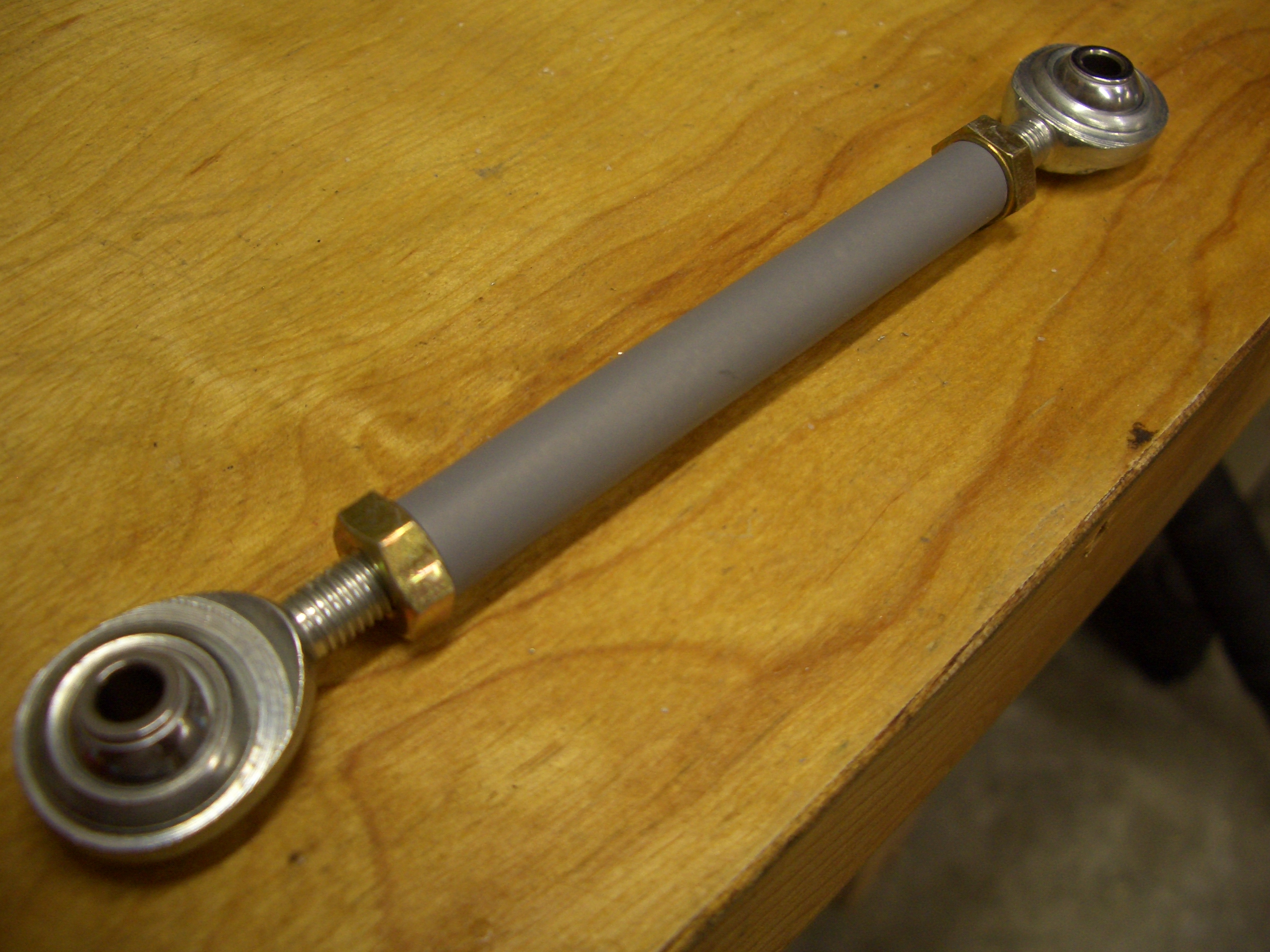
I also fabricated the pushrod that the autopilot roll servo will use to drive the aileron bellcrank.
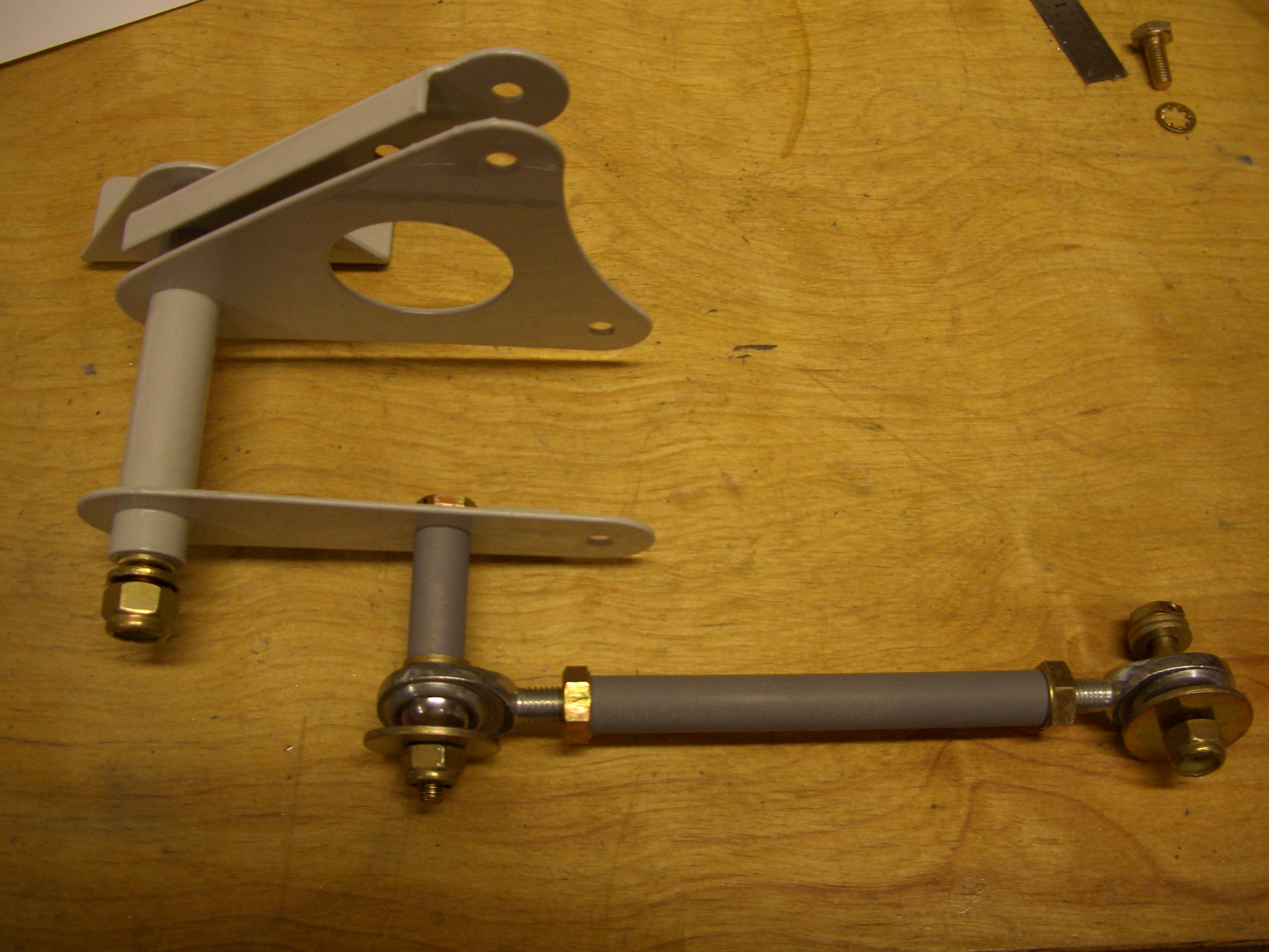
Here is how the pushrod attaches to the bellcrank. When I get the roll servo, all of this can be installed in the wing permanently.
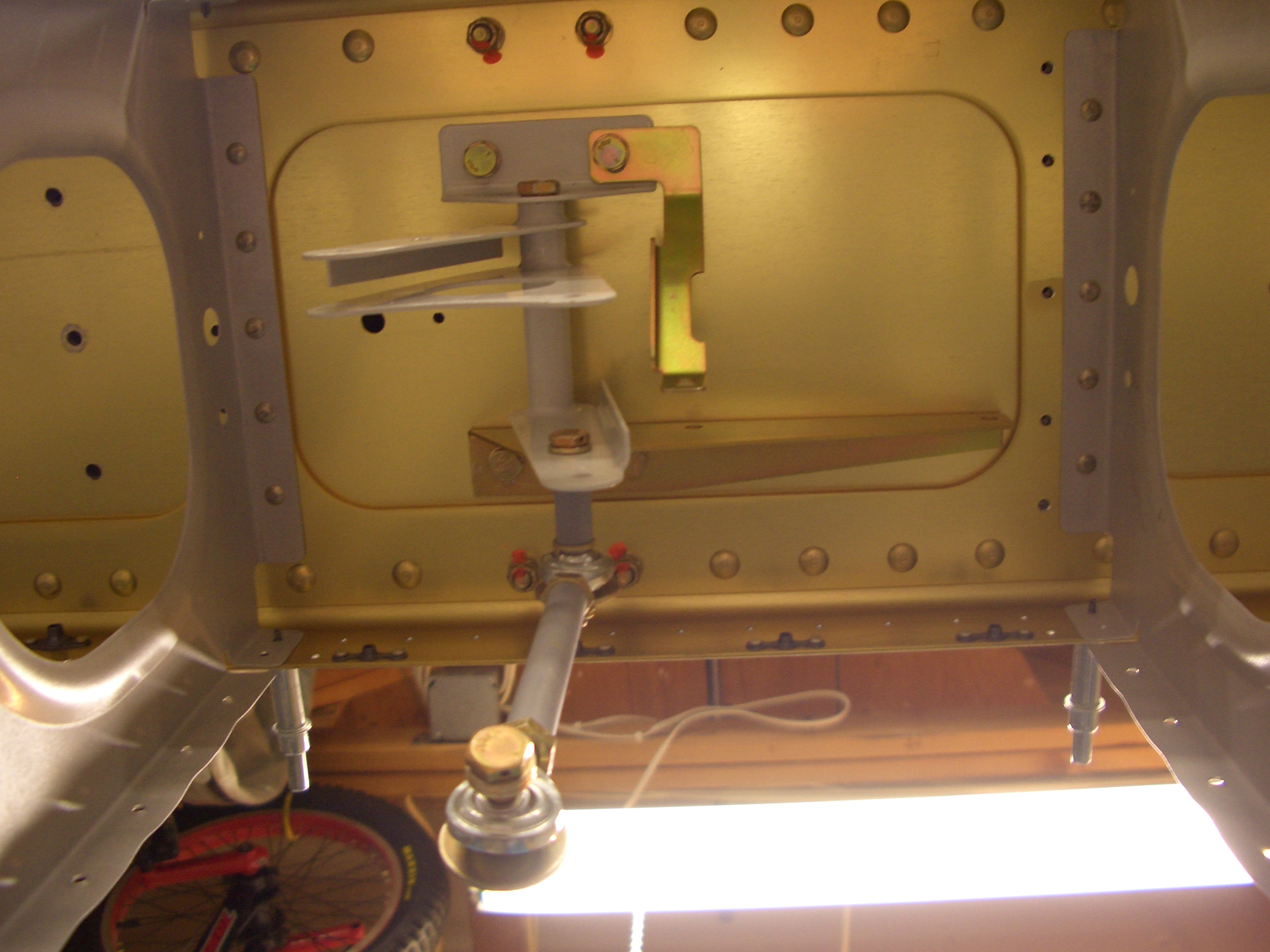
I picked up some Aeroshell 7 grease today and installed the aileron bellcranks permanently. When torqued to the wing, I found I had a little bit of binding. I traced this to making the brass bushings about 0.030″ too short. The plans say to make them 1/64″ to 1/32″ longer than the steel bellcrank tube, but you really want to make them whatever length will just fit between the brackets. I ended up elongating the holes in the upper brackets to allow them to be installed without bending towards the bushing. Here is the right bellcrank with autopilot servo pushrod (currently just hanging down) installed. This side also has a longer bracket on the bottom side of the wing where the servo will mount and a brace that is installed diagonally from the top bracket to the servo (you’ll see when I install the servo).
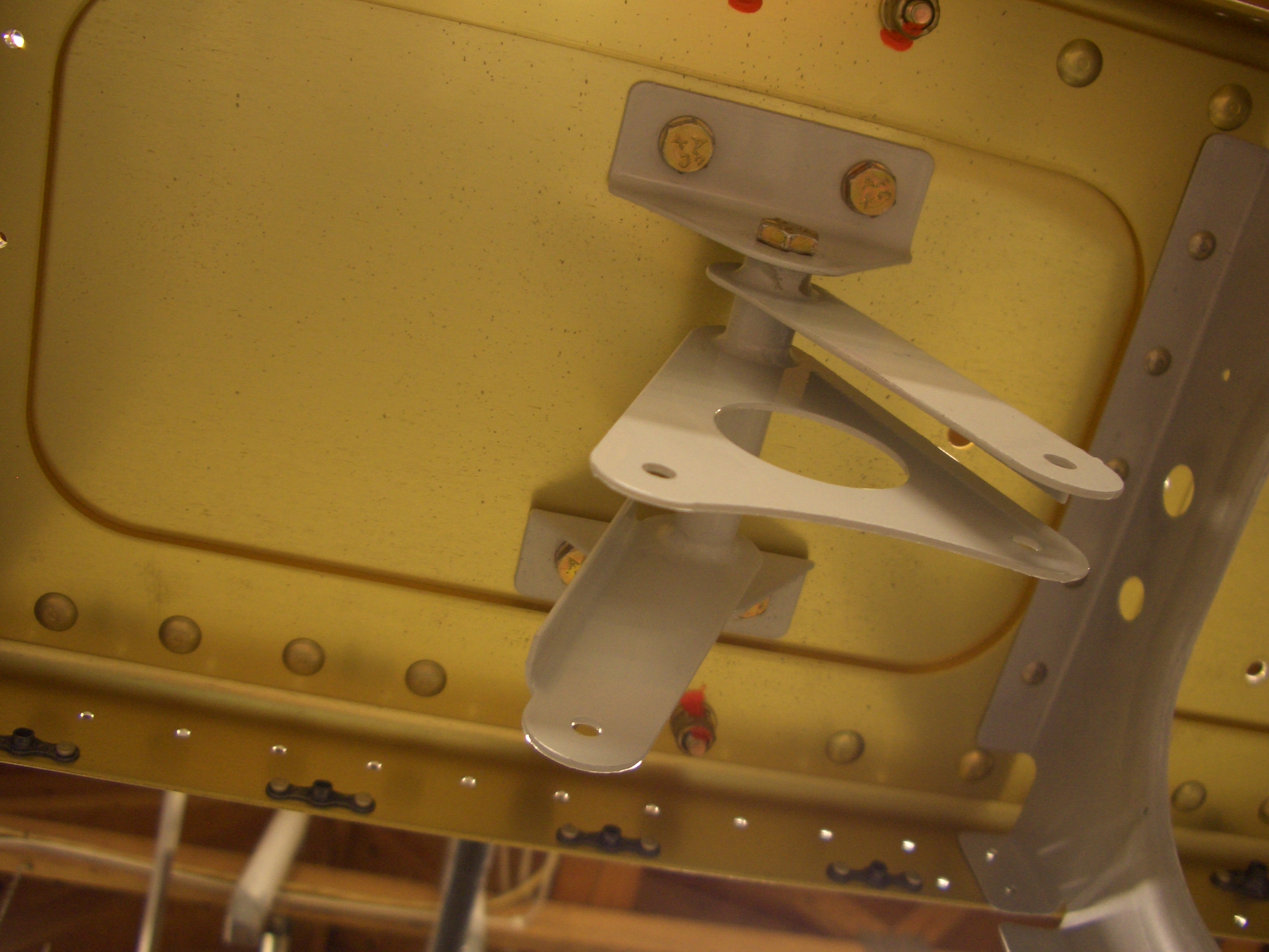
Here is the bracket installed in the left wing.
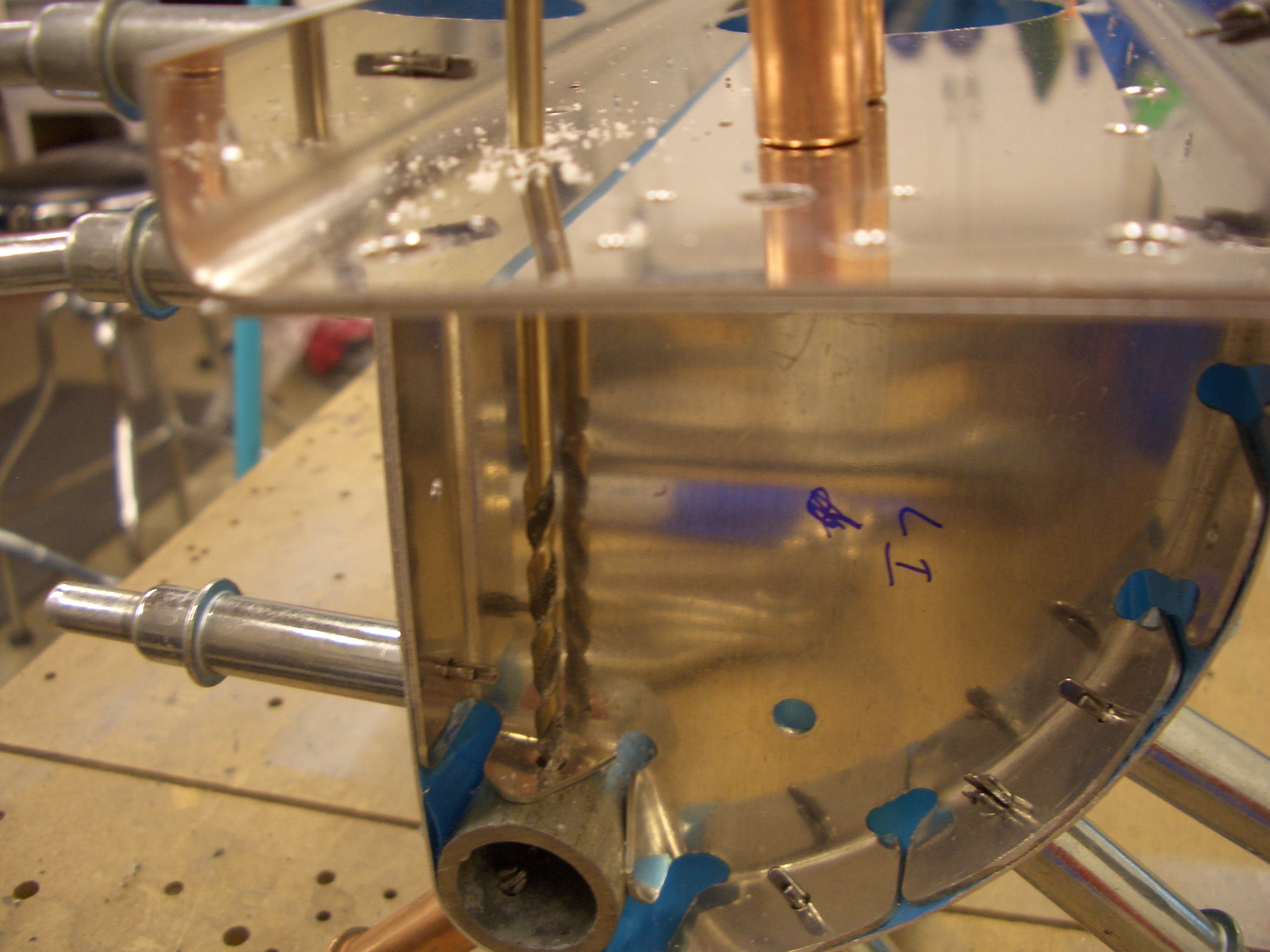
To install the leading edges, you need to grind away part of a double offset rivet set because the manufactured heads are right up against the main wing ribs. This allows you to get the rivet set square to the rivet.
Really jumping around now, I pulled out the rough stock for the aileron stiffeners and cut them down to size and began cutting the tapers.
I finished trimming and deburring the aileron stiffeners.
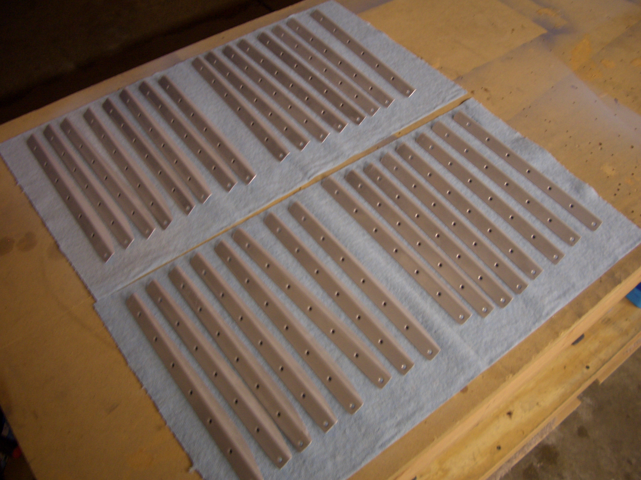
I went out before work this morning and backriveted all of the stiffeners on both of the aileron skins.
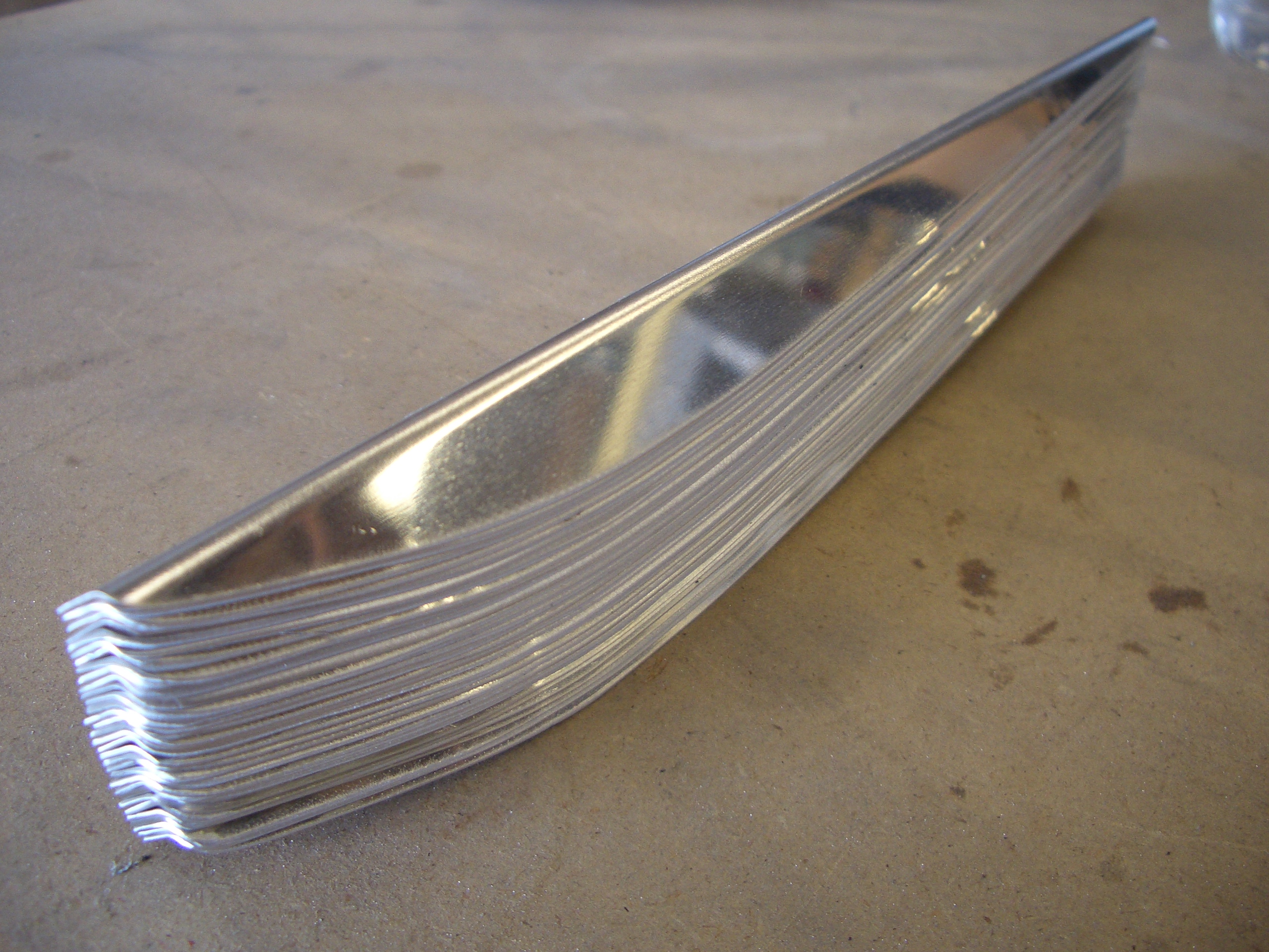
Using the bending brake I made for the empennage skins, I bent the aileron skins. I ended up having to fine tune the bends with the hand seamer. Just like on the elevators, you want the skin to stay perfectly straight from the spar back to the trailing edge radius.
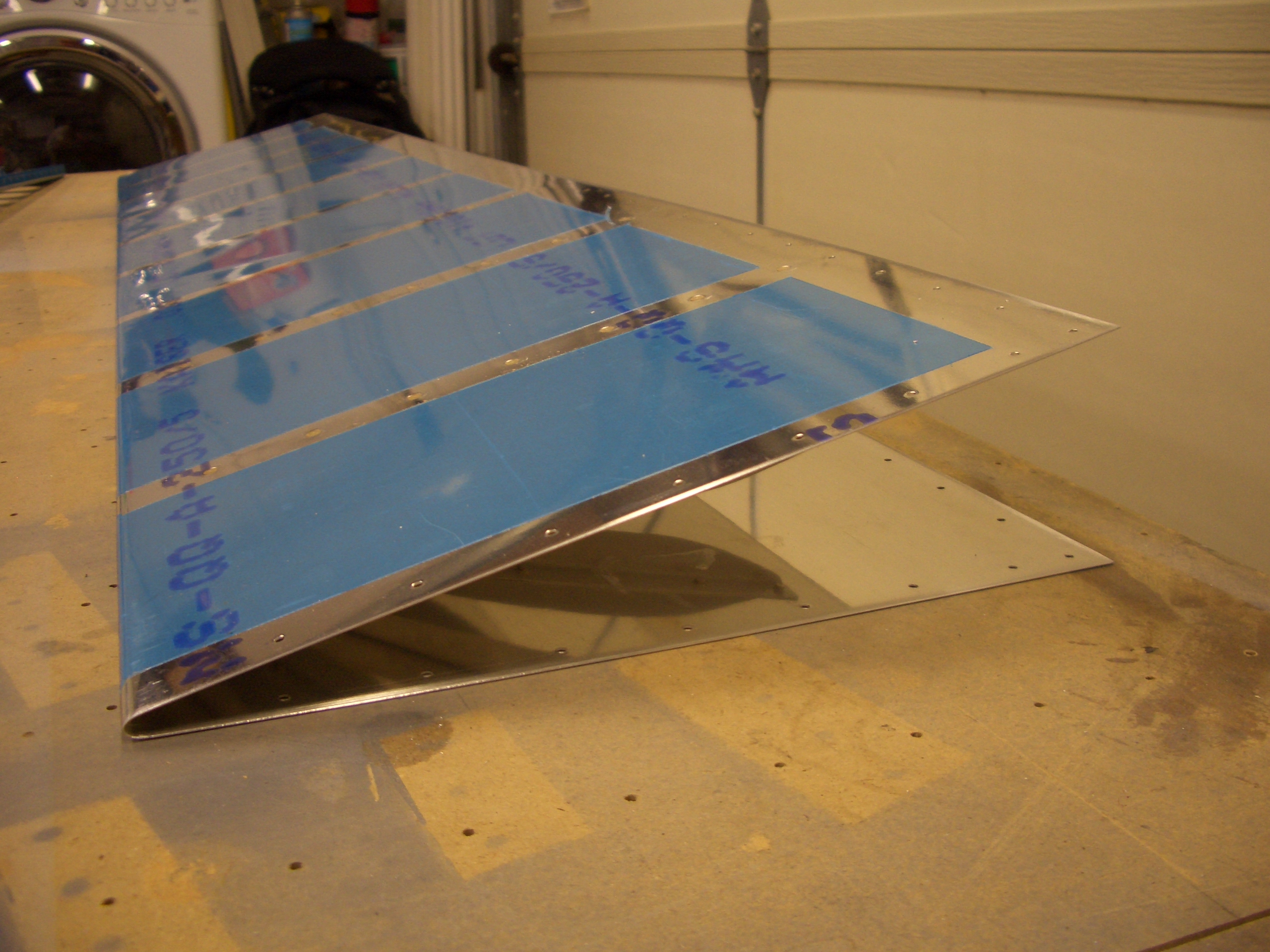
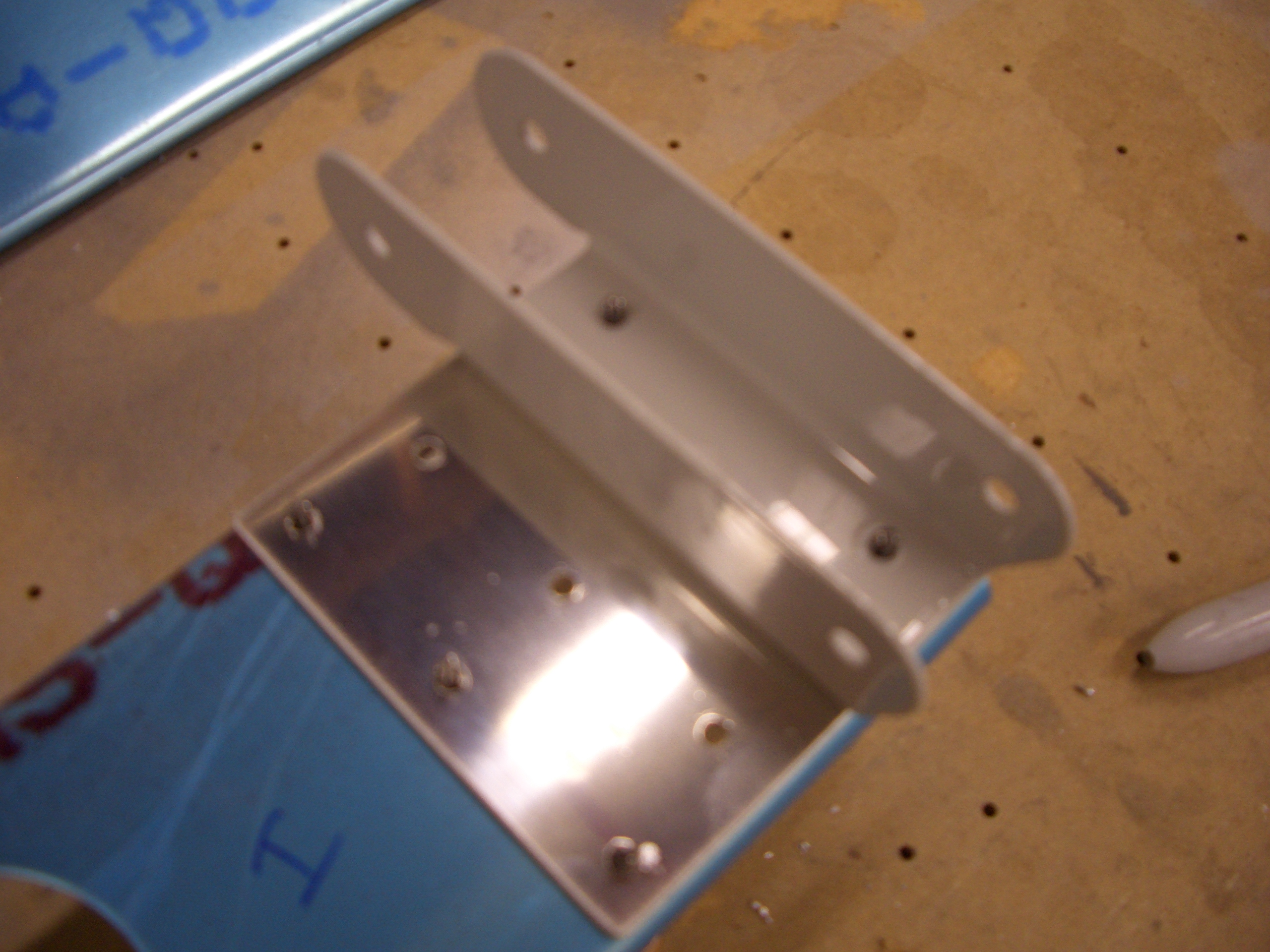
The ends of the aileron spars need reinforcing plates where the hinge brackets attach. These are made from 0.040″ aluminum and match drilled to the spars.
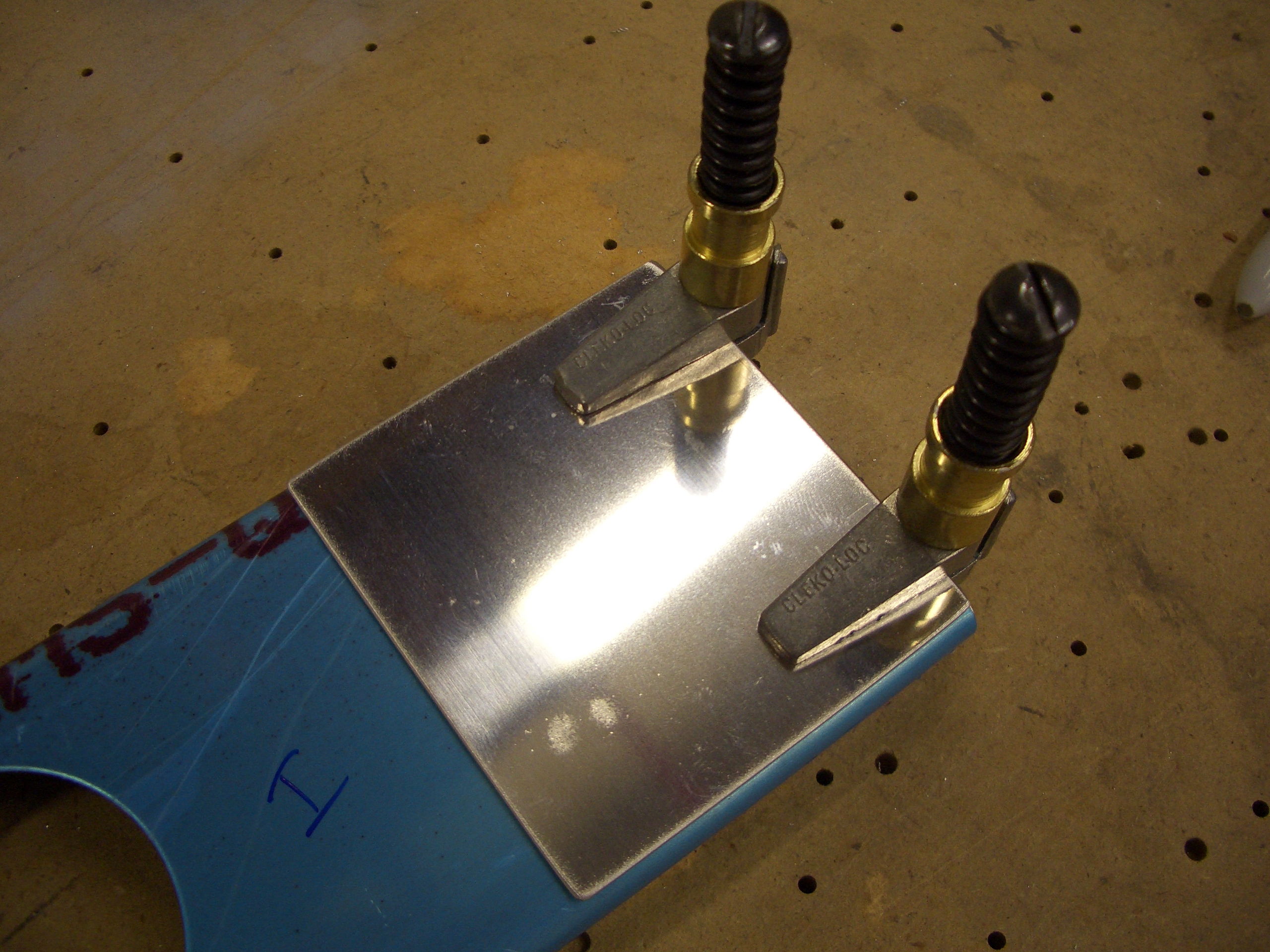
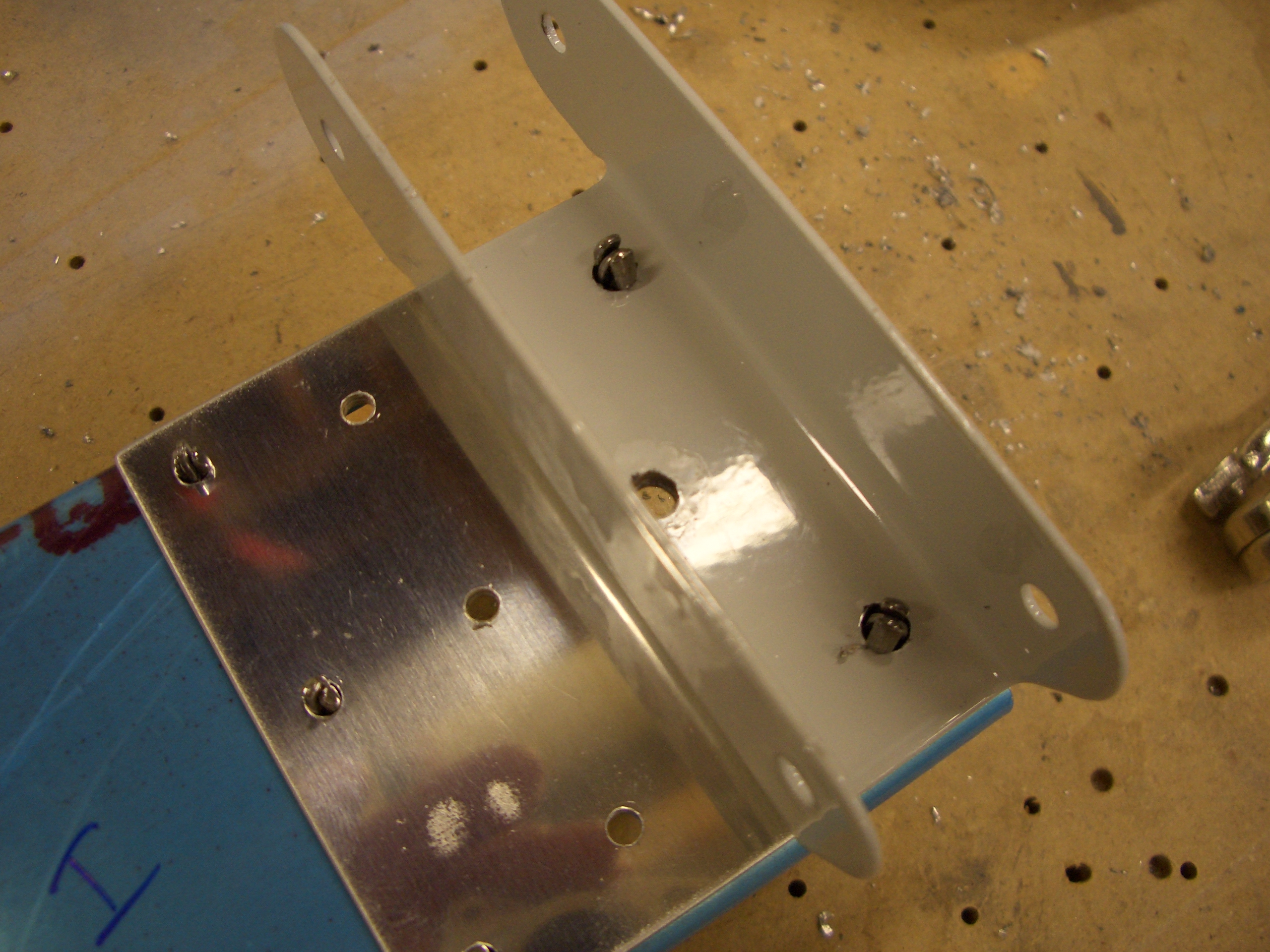
After match drilling, the hinge brackets are clecoed on…
…and drilled out with a #12 drill for AN3 bolts.
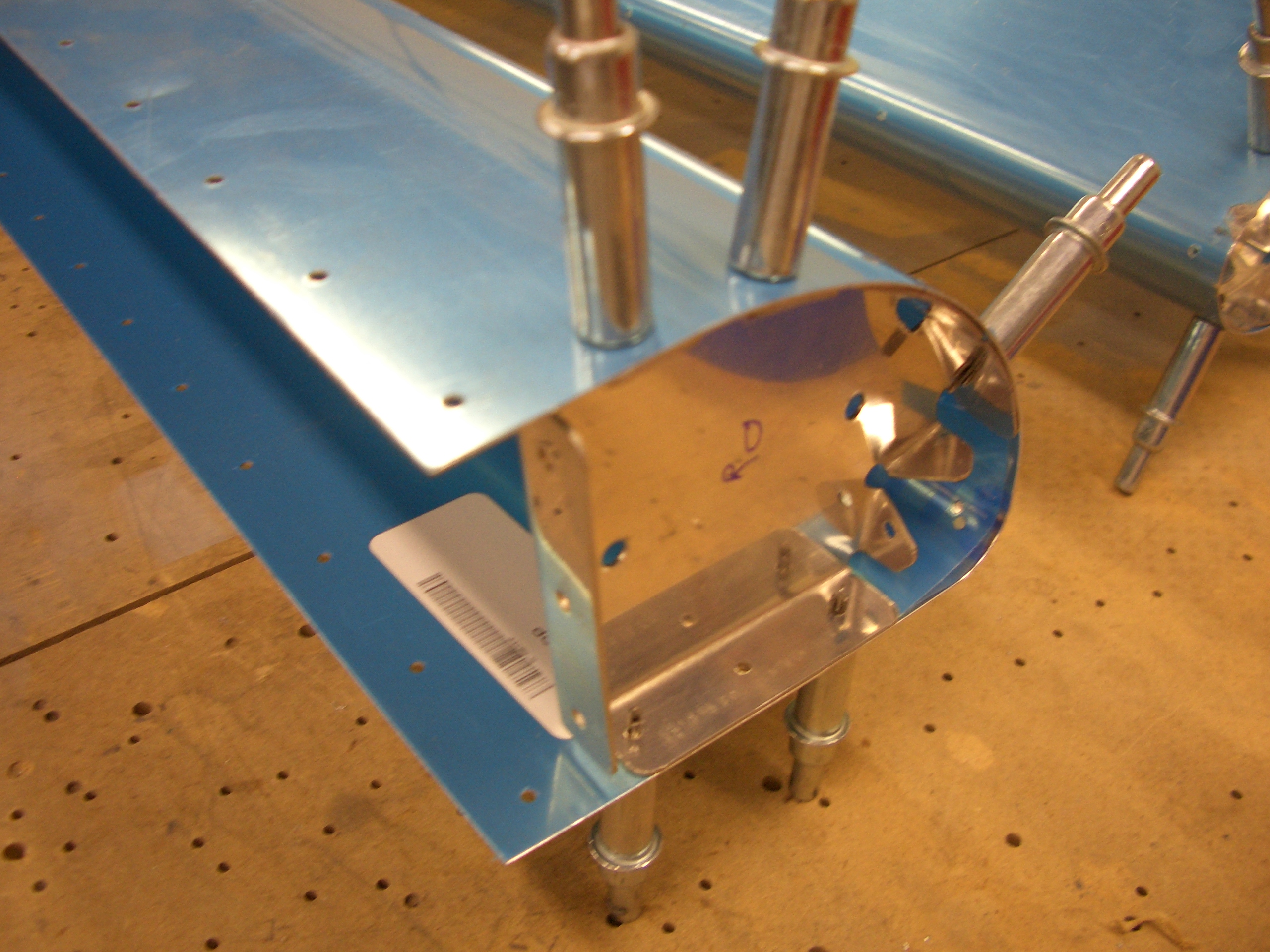
Before calling it a night, I also clecoed the leading edge ribs in place and match drilled them to the skin.
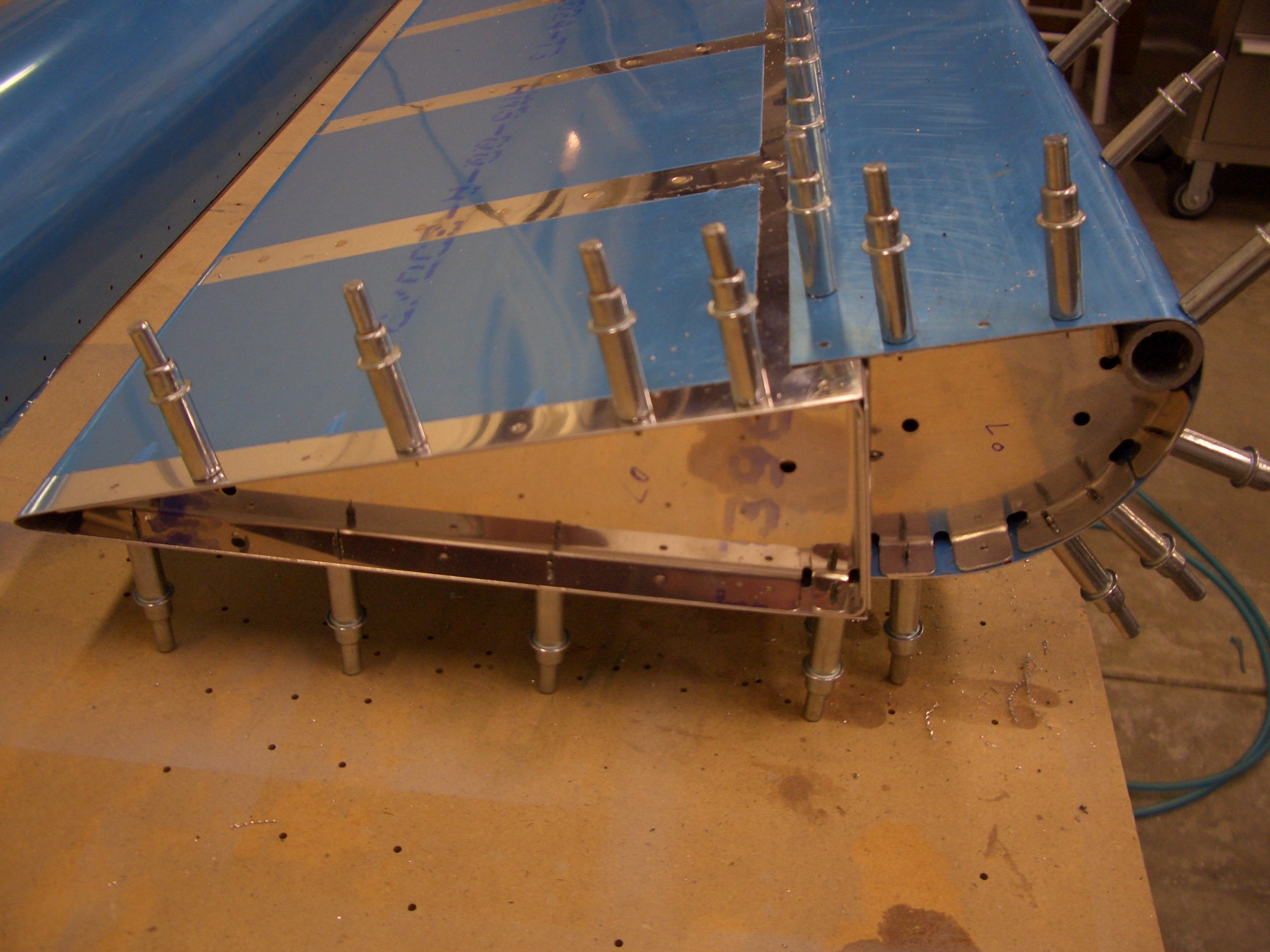
I clecoed the left aileron completely together in preparation for match drilling.
No pictures tonight as they would be indistinguishable from yesterday’s. Basically, I repeated all of yesterday’s steps on the right aileron, but I did it quite a bit quicker tonight since I didn’t need to refer to the instructions. Afterward, I got started deburring some of the components. Van’s instructions have you prime at several points along the construction. Instead, other than the stiffeners, I’m waiting until all of the aileron components are ready to prime at the same time.