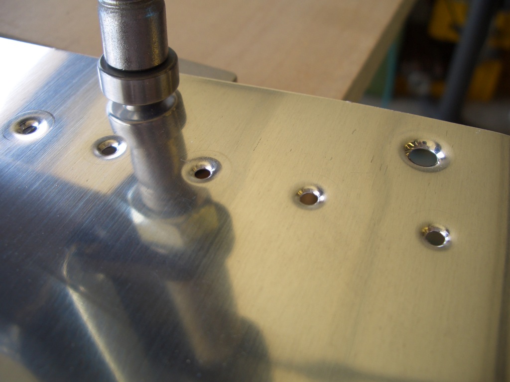
My buddy Andre stopped by today to help me work on the fuel tanks. I had a few details to wrap up before starting to use the sealant. First up is to debur and dimple the #8 screw holes on the perimeter of the tanks.
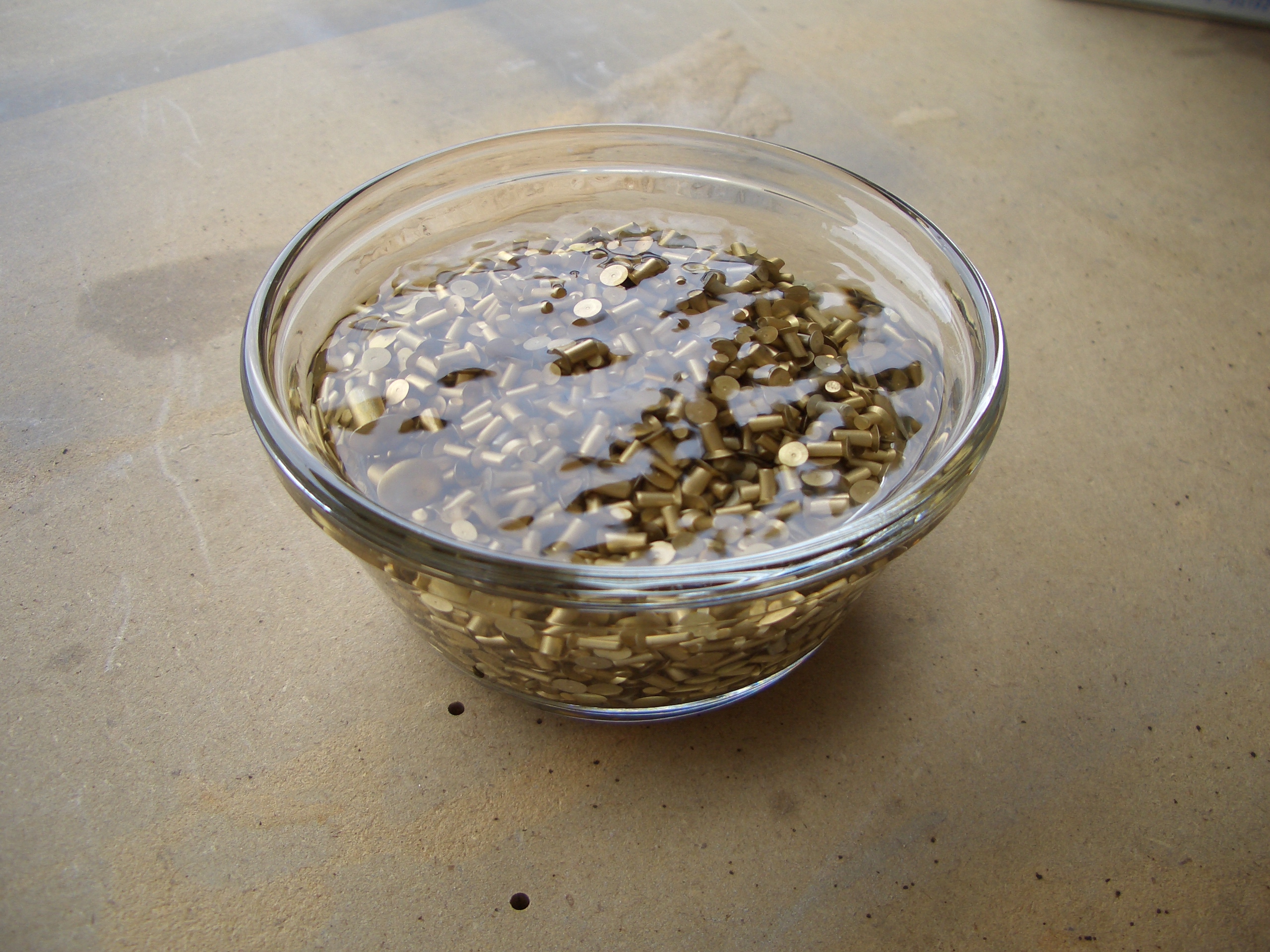
The rivets need to be cleaned by sloshing them around in some MEK.

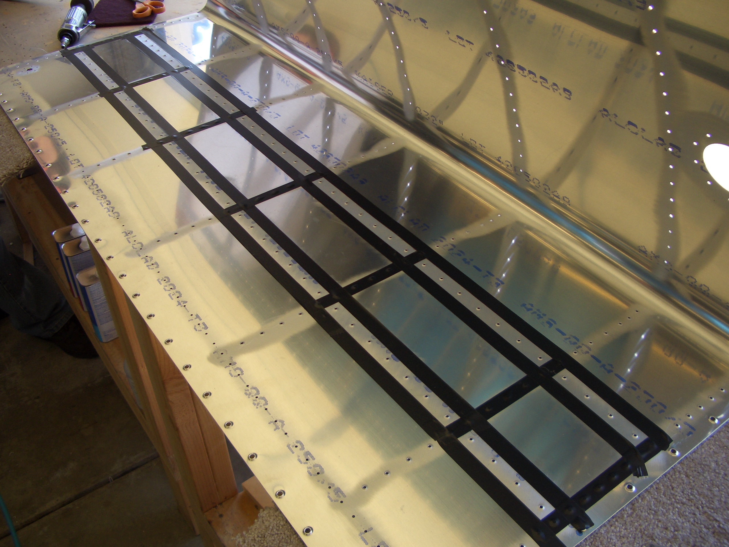
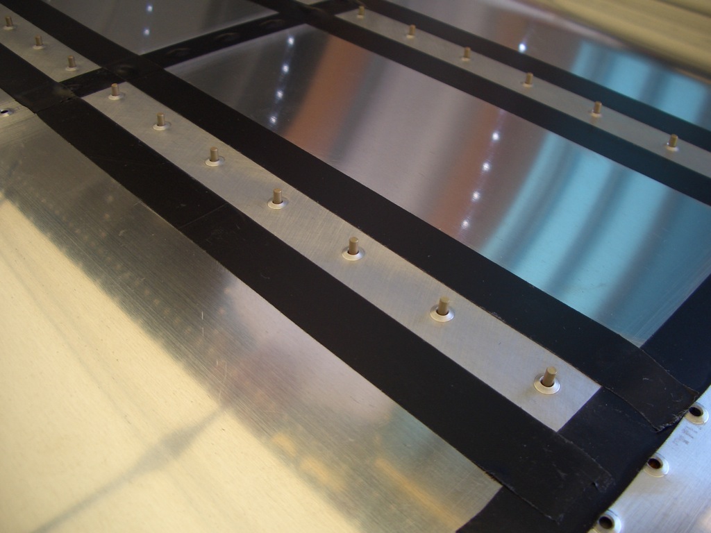
I lined the area around the stiffeners with electrical tape to keep the tank sealant from making too big a mess.

Rivets are installed in the holes and held in place with rivet tape.
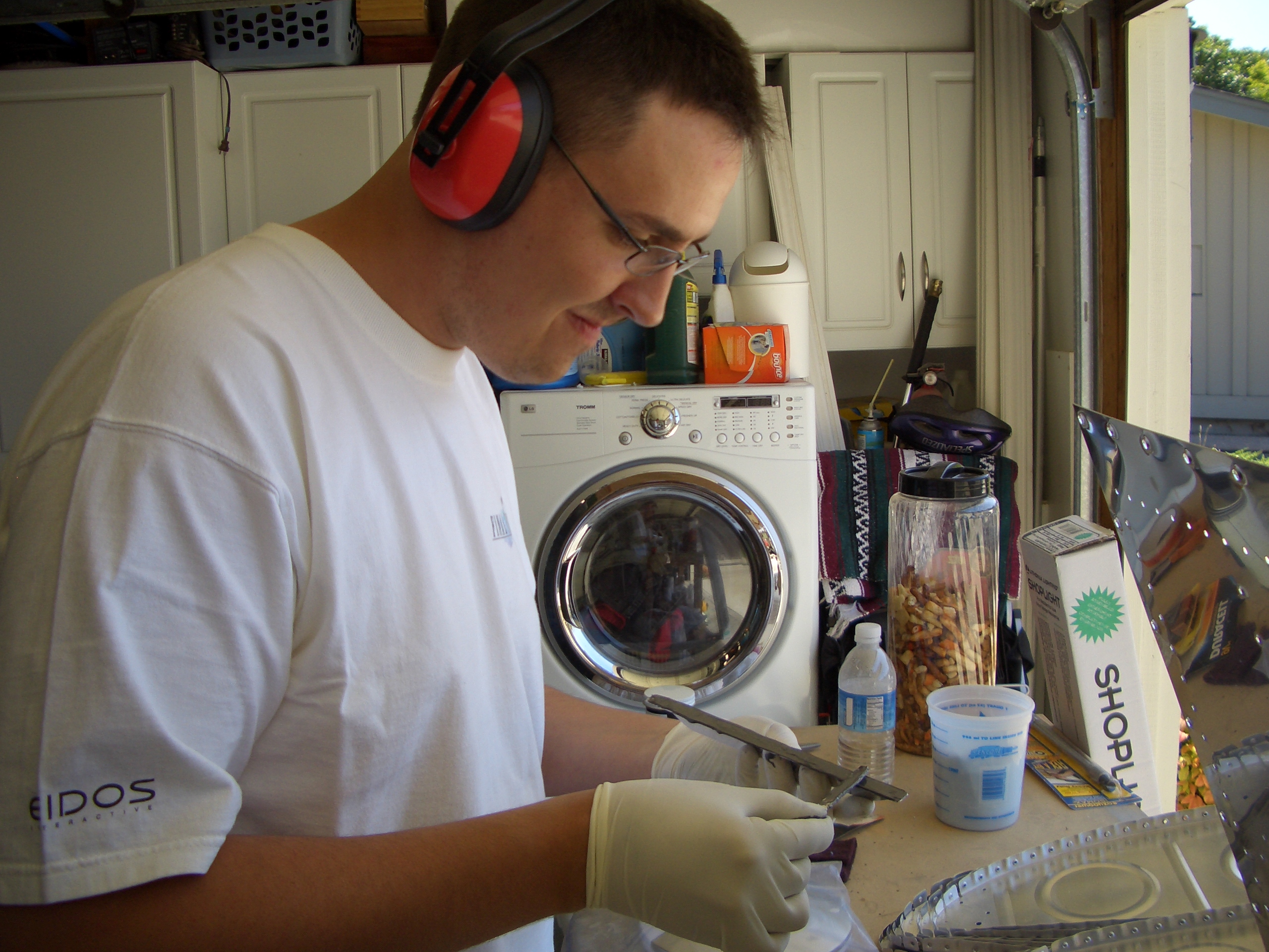
Then the stiffeners are coated with a thin coat of sealant on the mating surface. Here is Andre in action.

They are then pressed over the rivets and back-riveted into place.
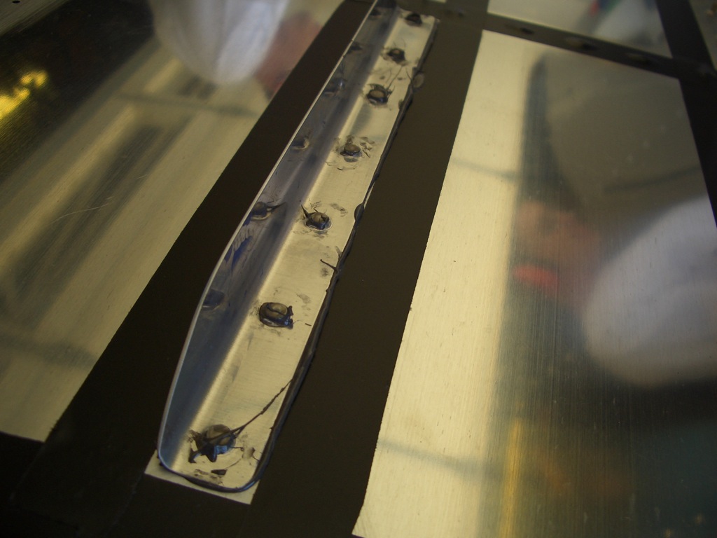
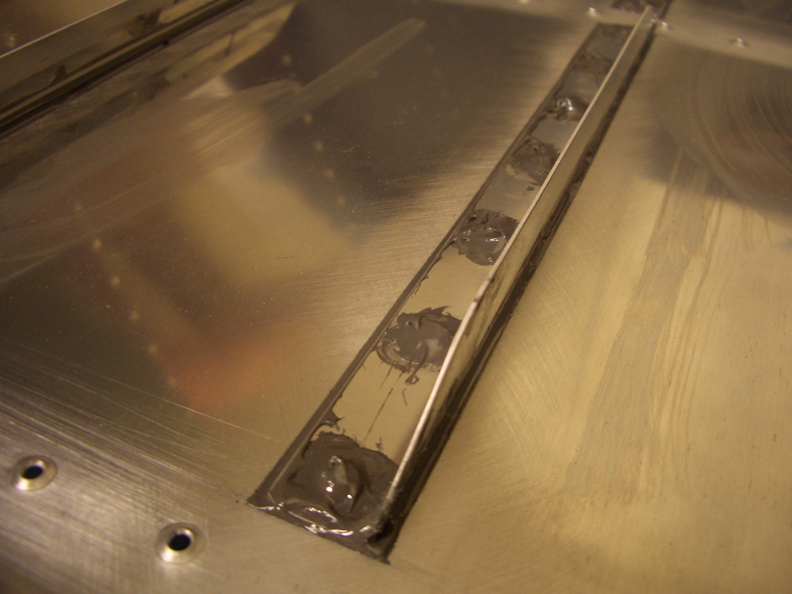
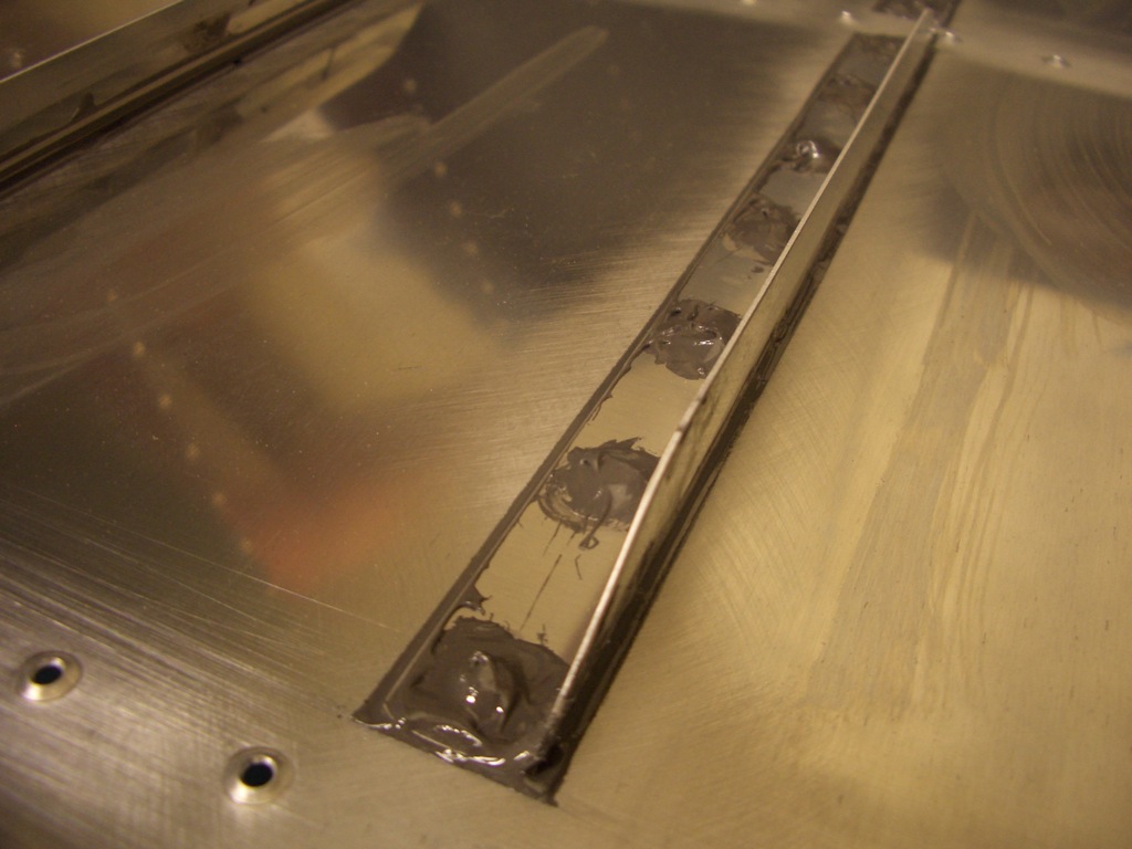
Then sealant is spread around the edge of the stiffener to create a filet and a dab of sealant is placed over each rivet.
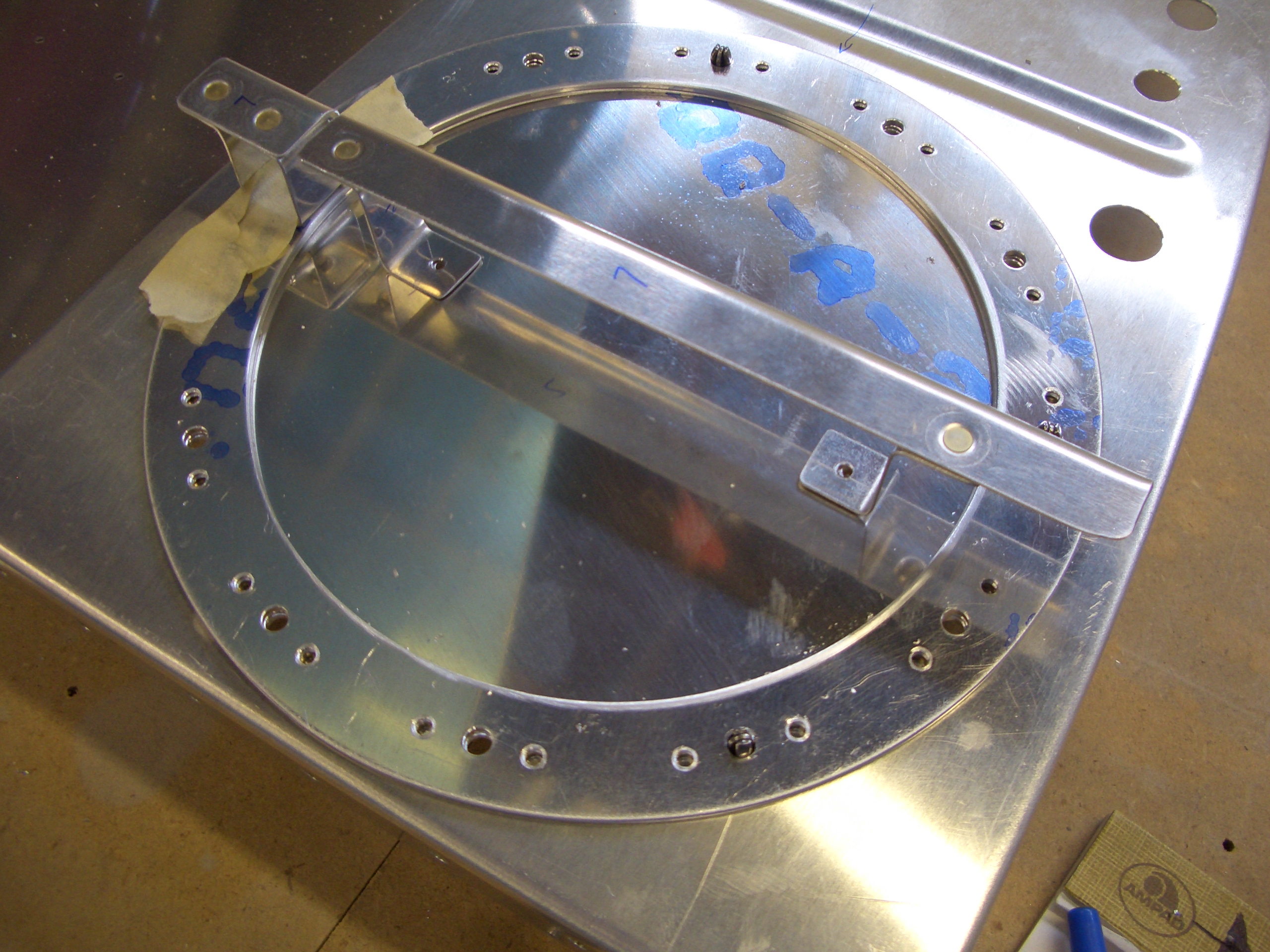
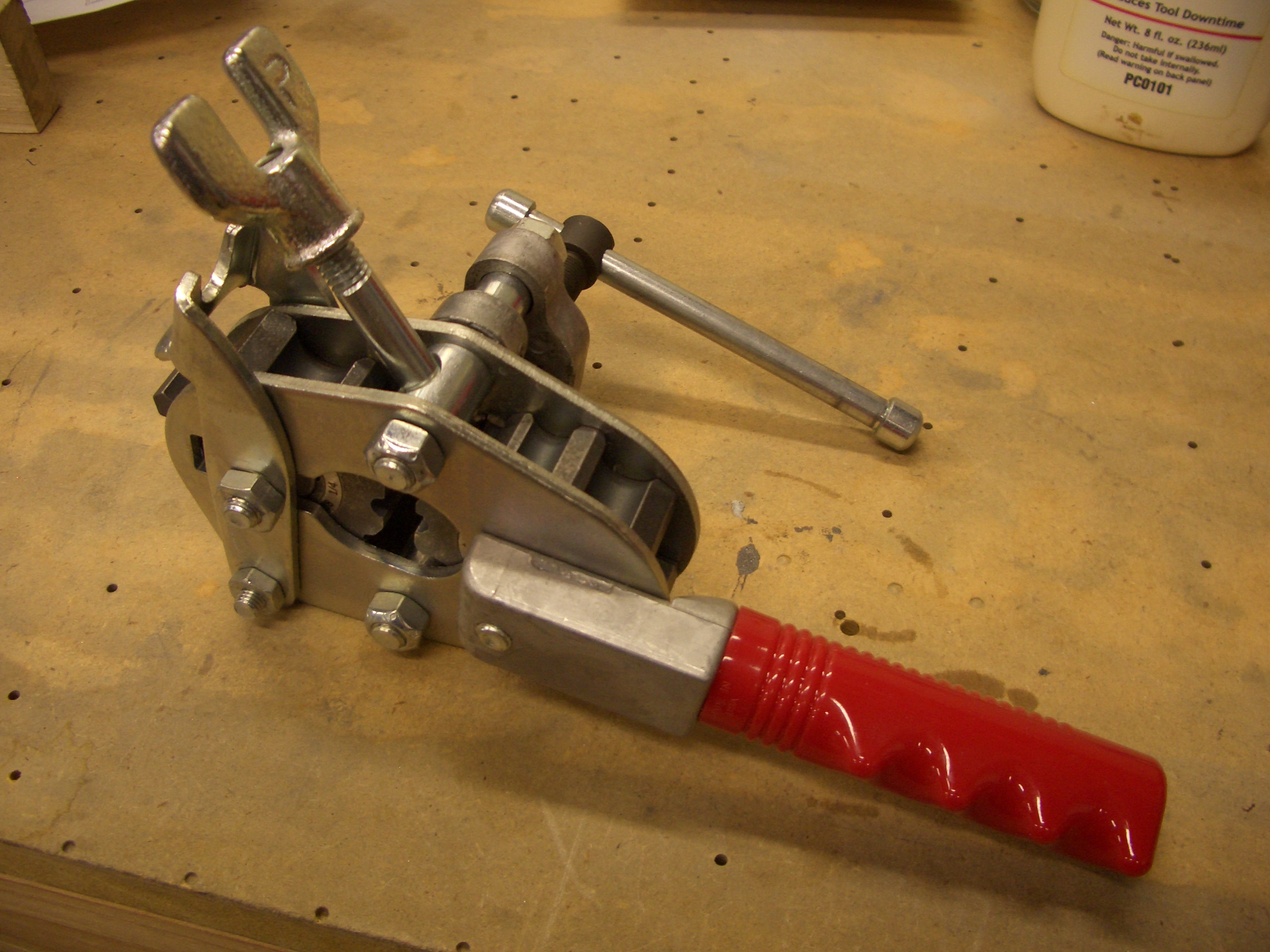
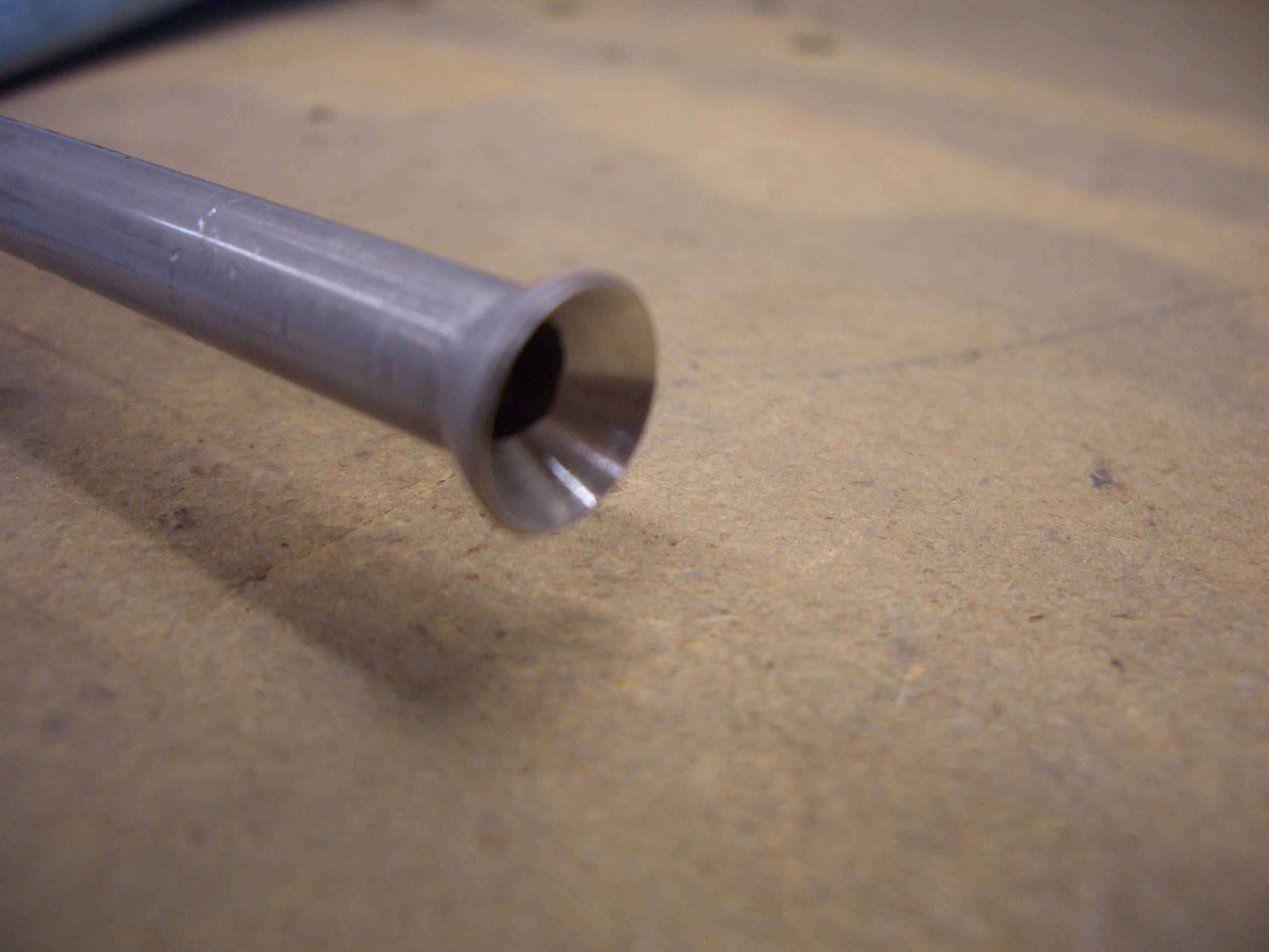
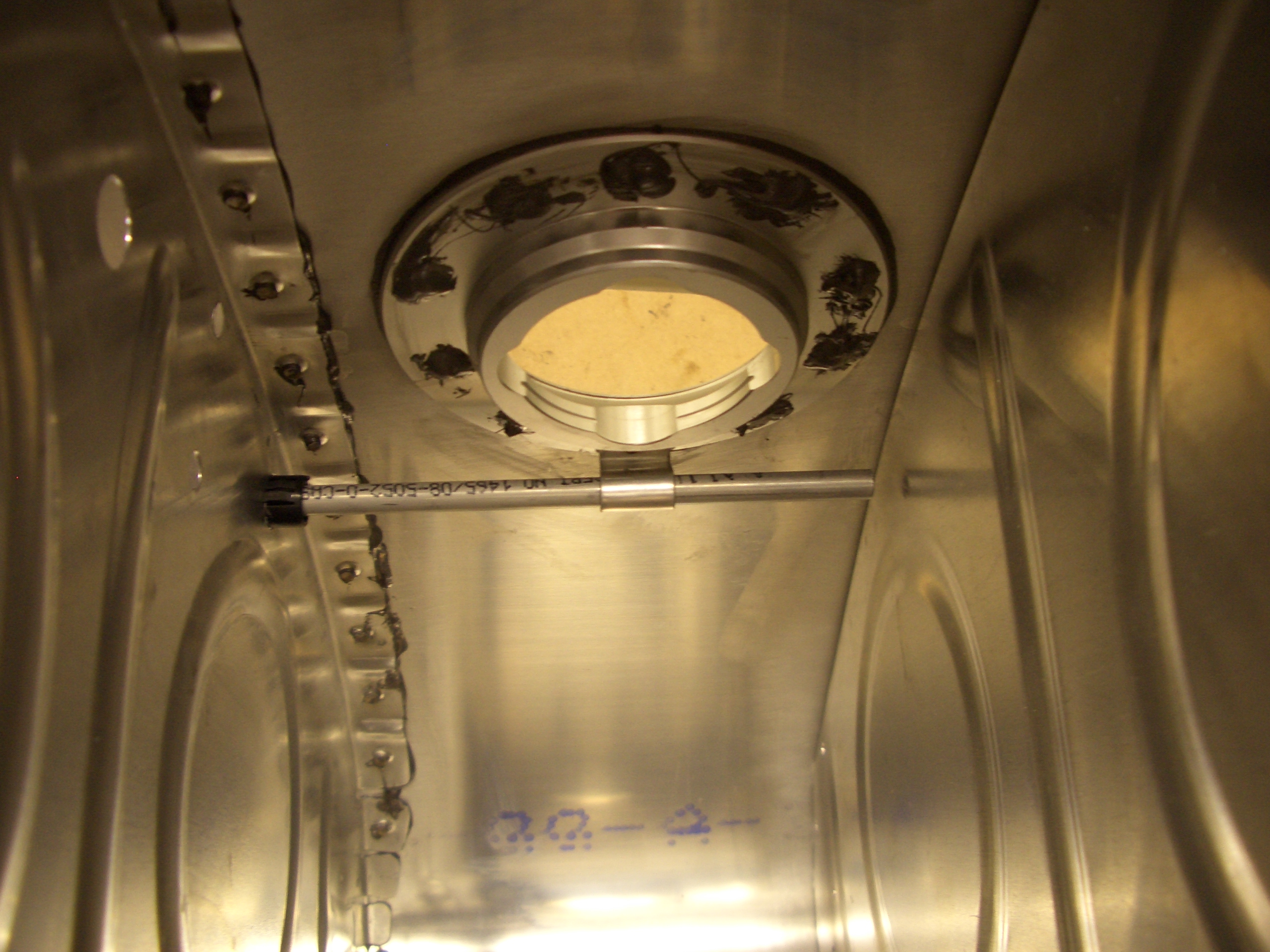
The fuel filler neck is then riveted on. We tried back-riveting these using a hand-held back-rivet bucking bar, but that didn’t work as well as expected and we had to drill out one of the rivets. Either back-rivet these on the plate or shoot/buck them.

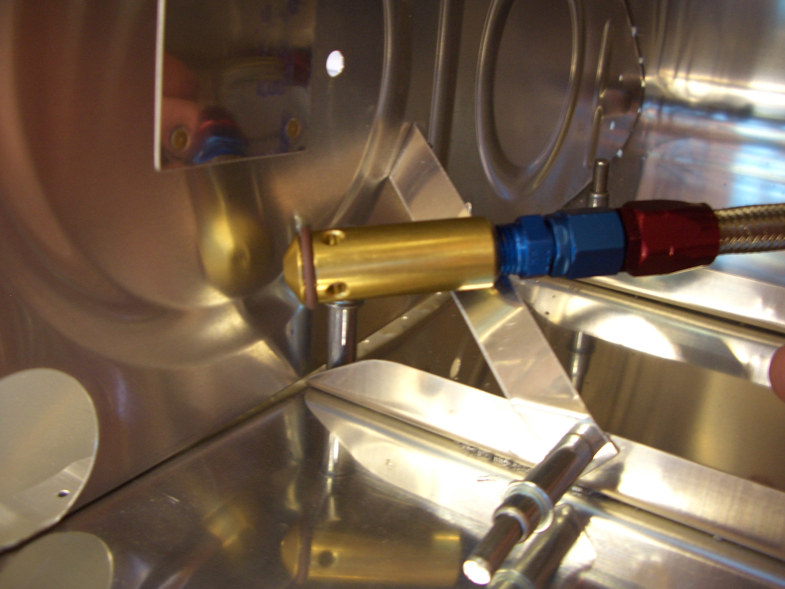
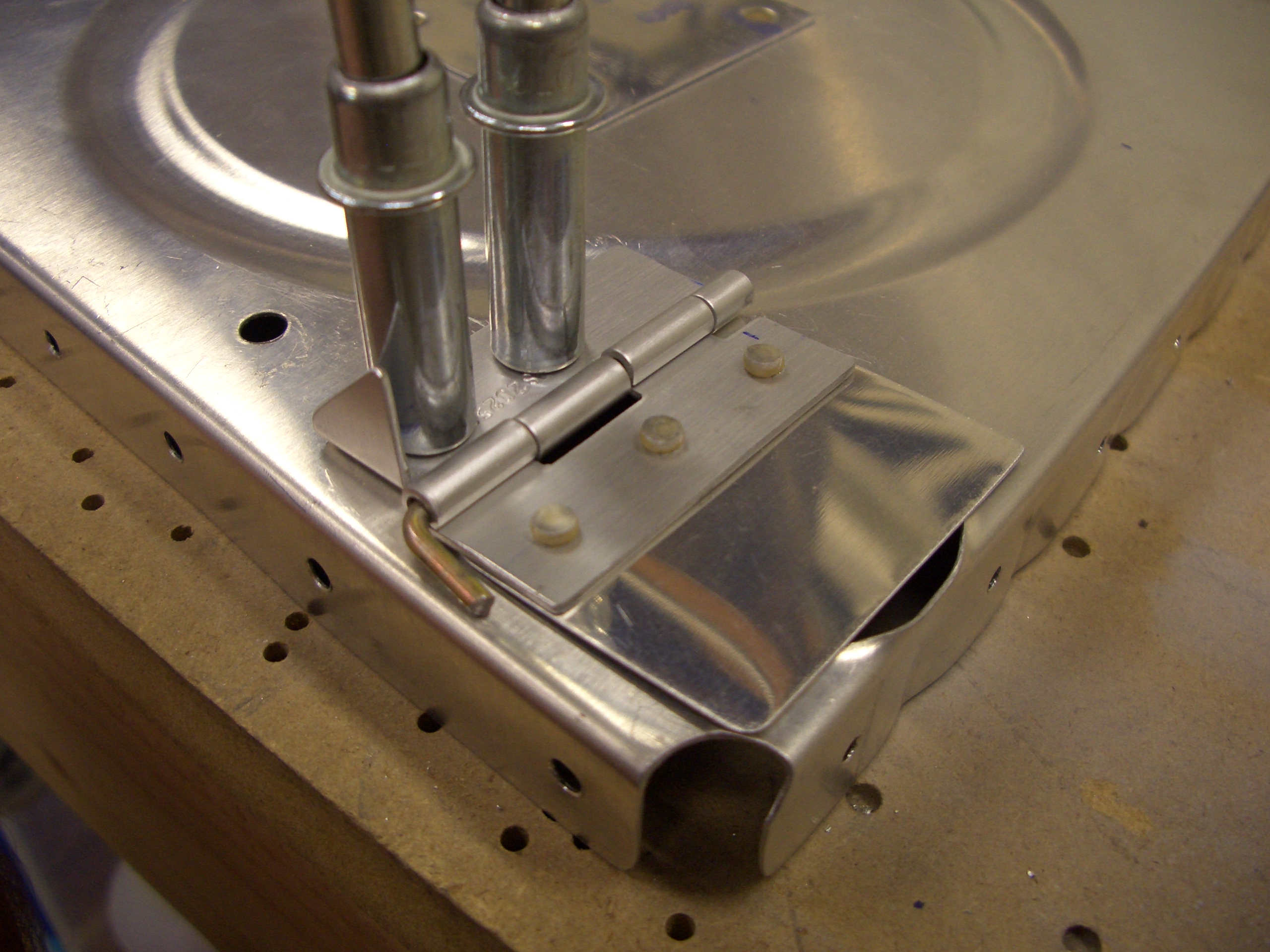
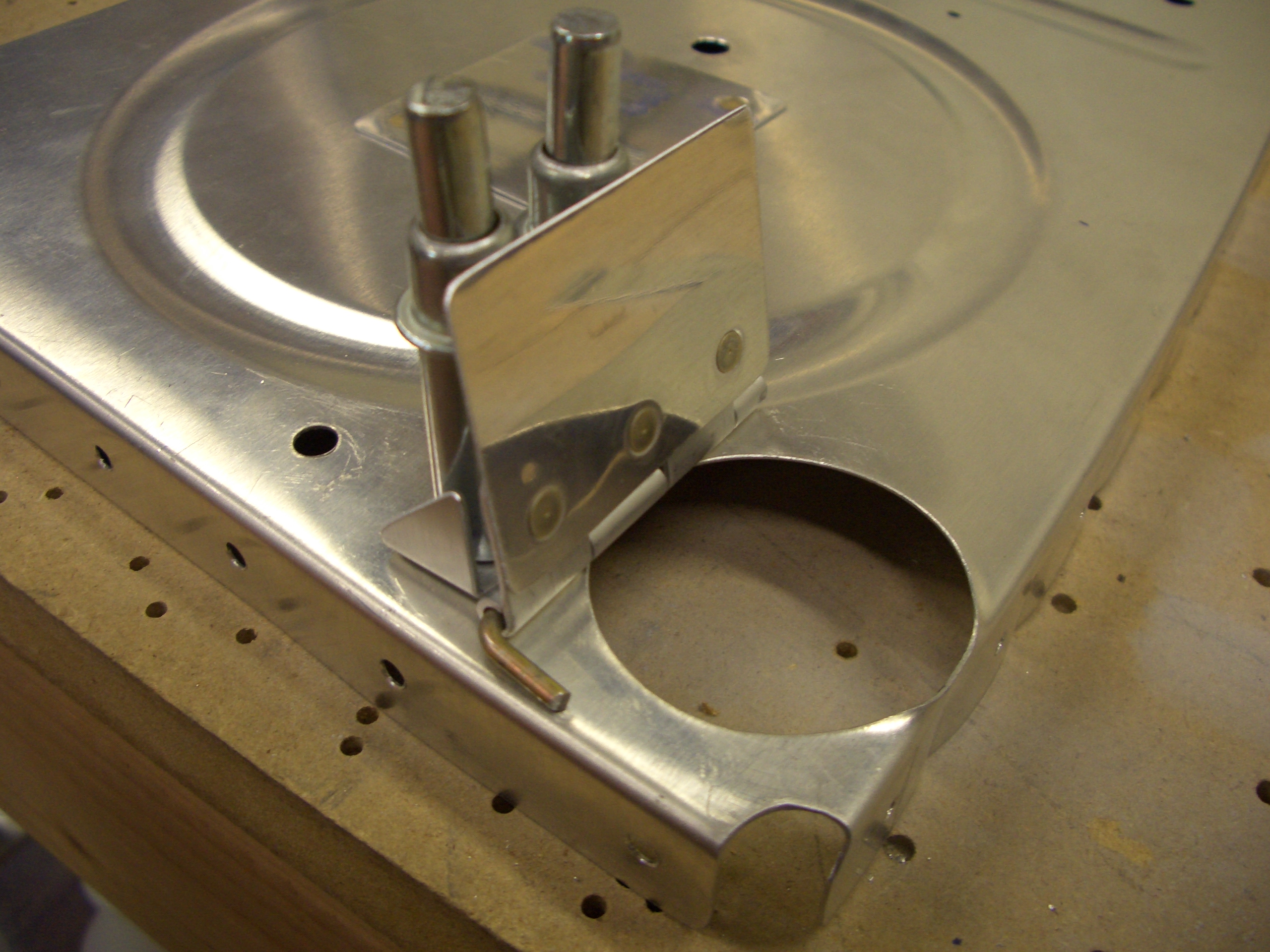
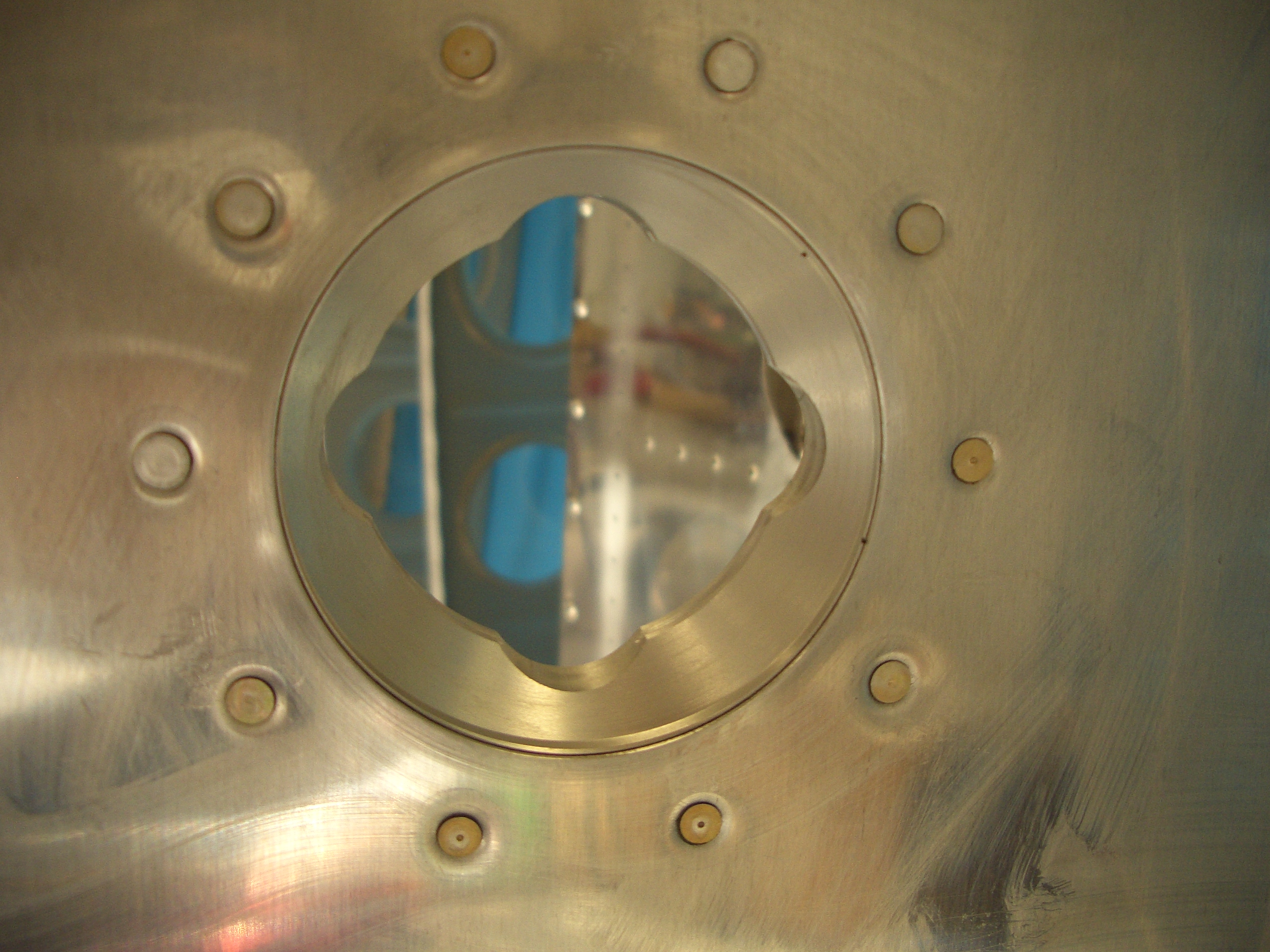
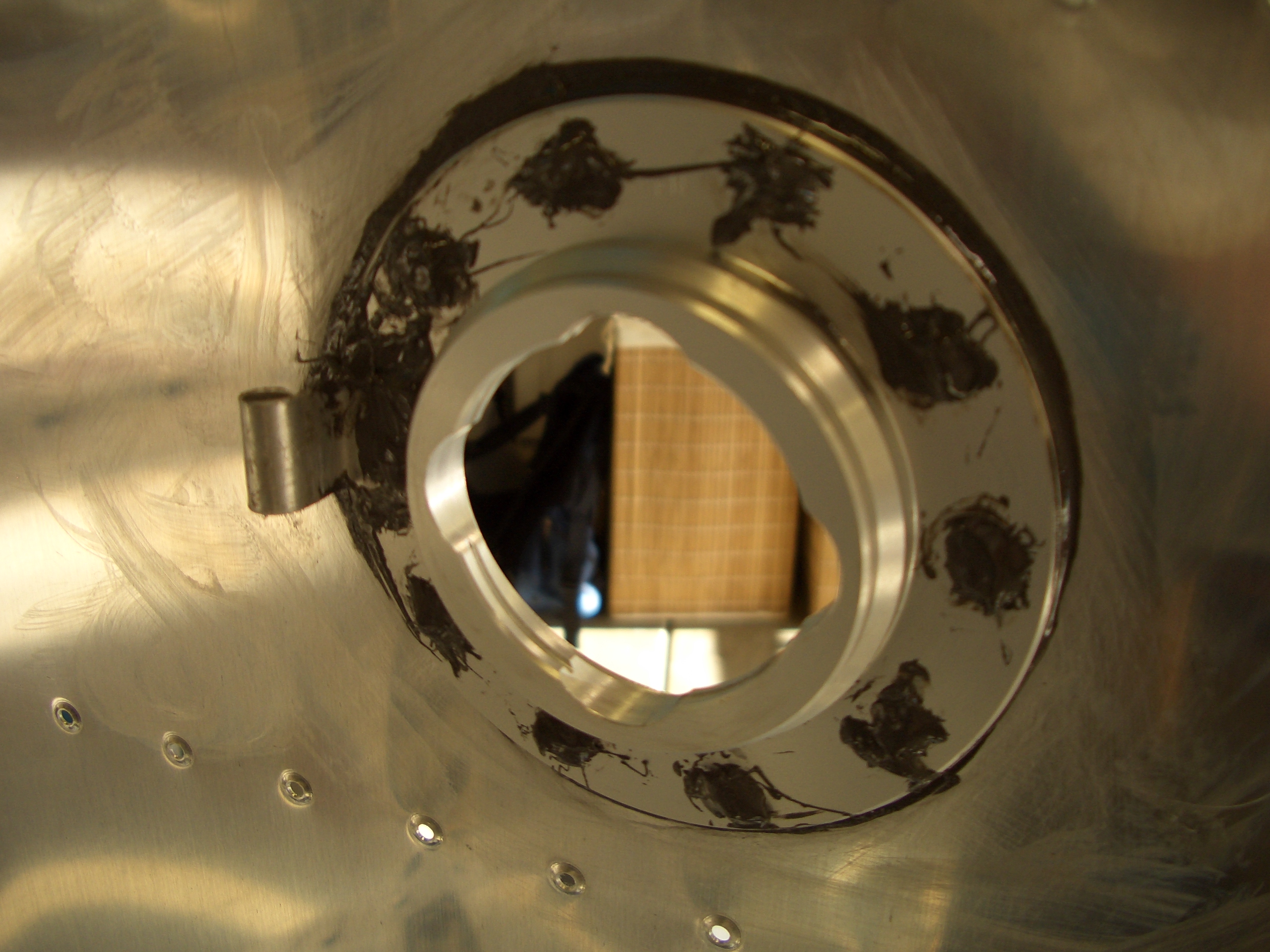
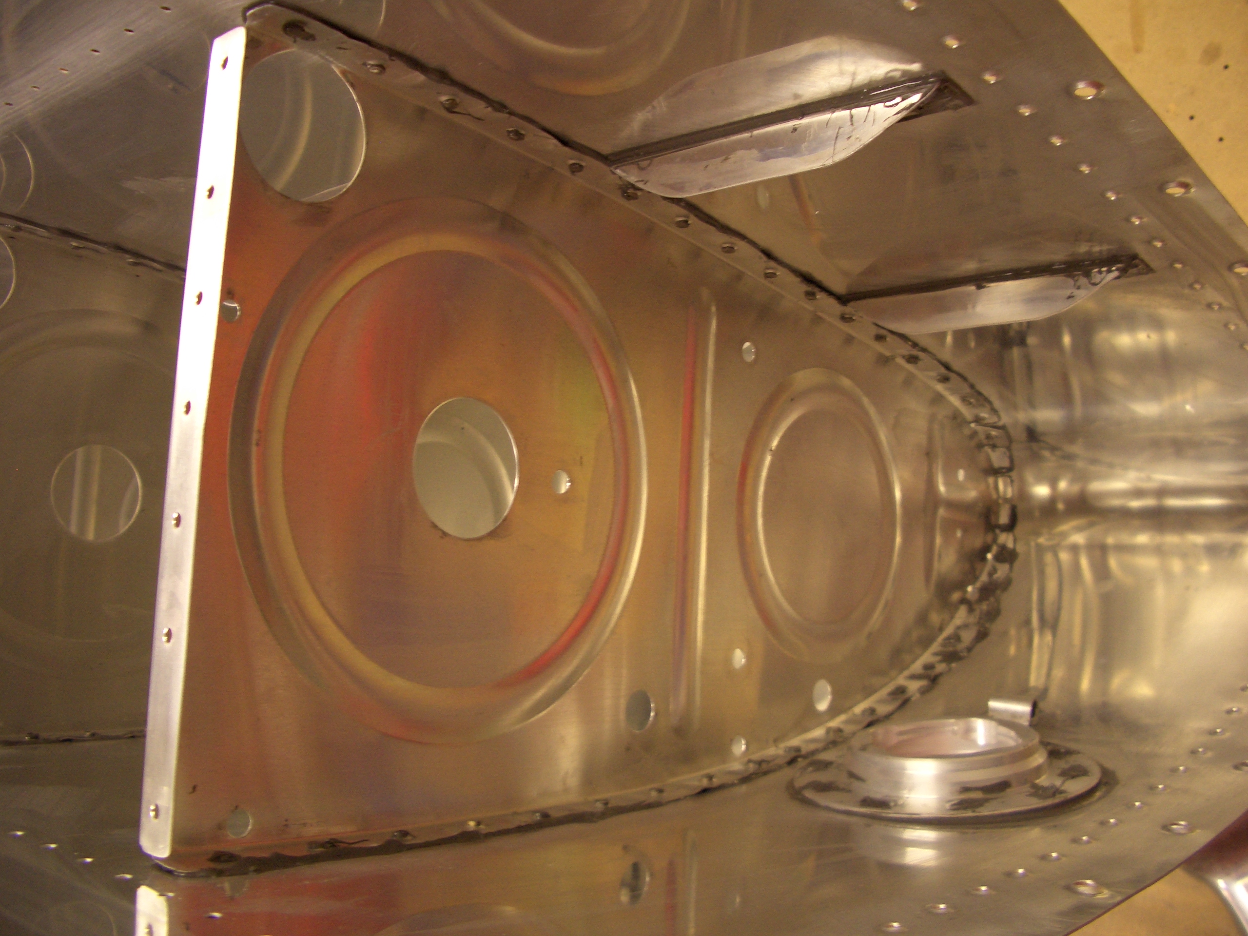
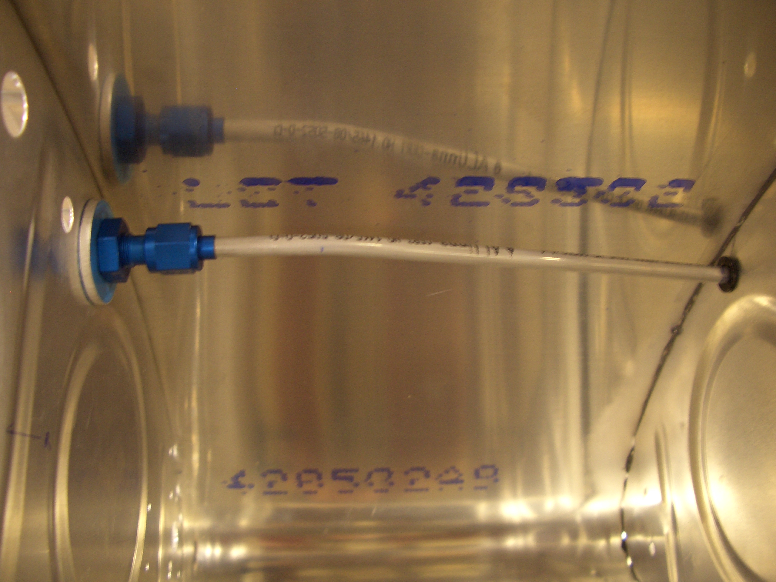
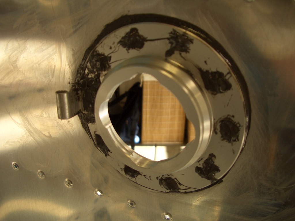
Here is the inside of the filler neck with the vent line retaining clip riveted in place.
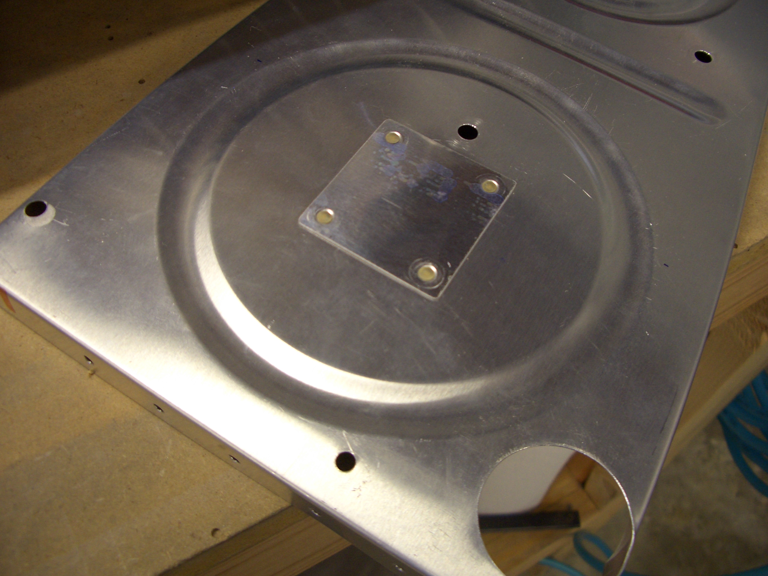
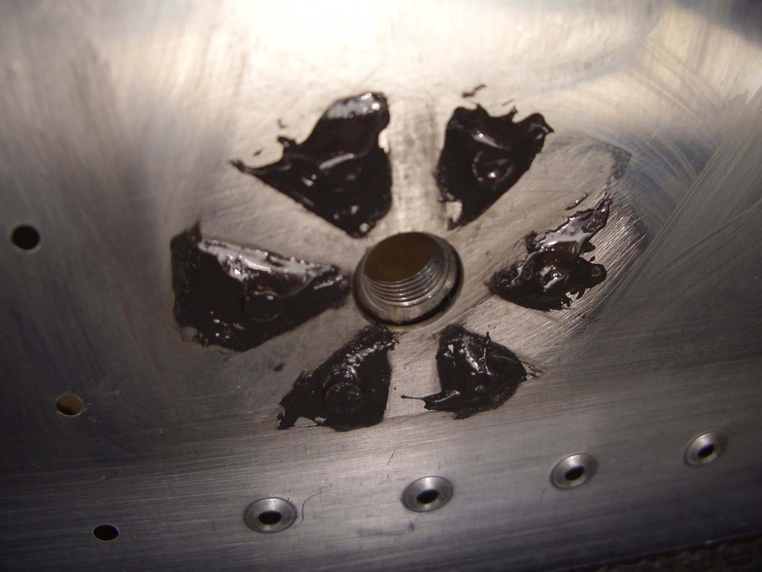
We also riveted on the fuel drain mounts. When you dab sealant over the rivets, be sure and leave some channels so that water can make its way to the drain.

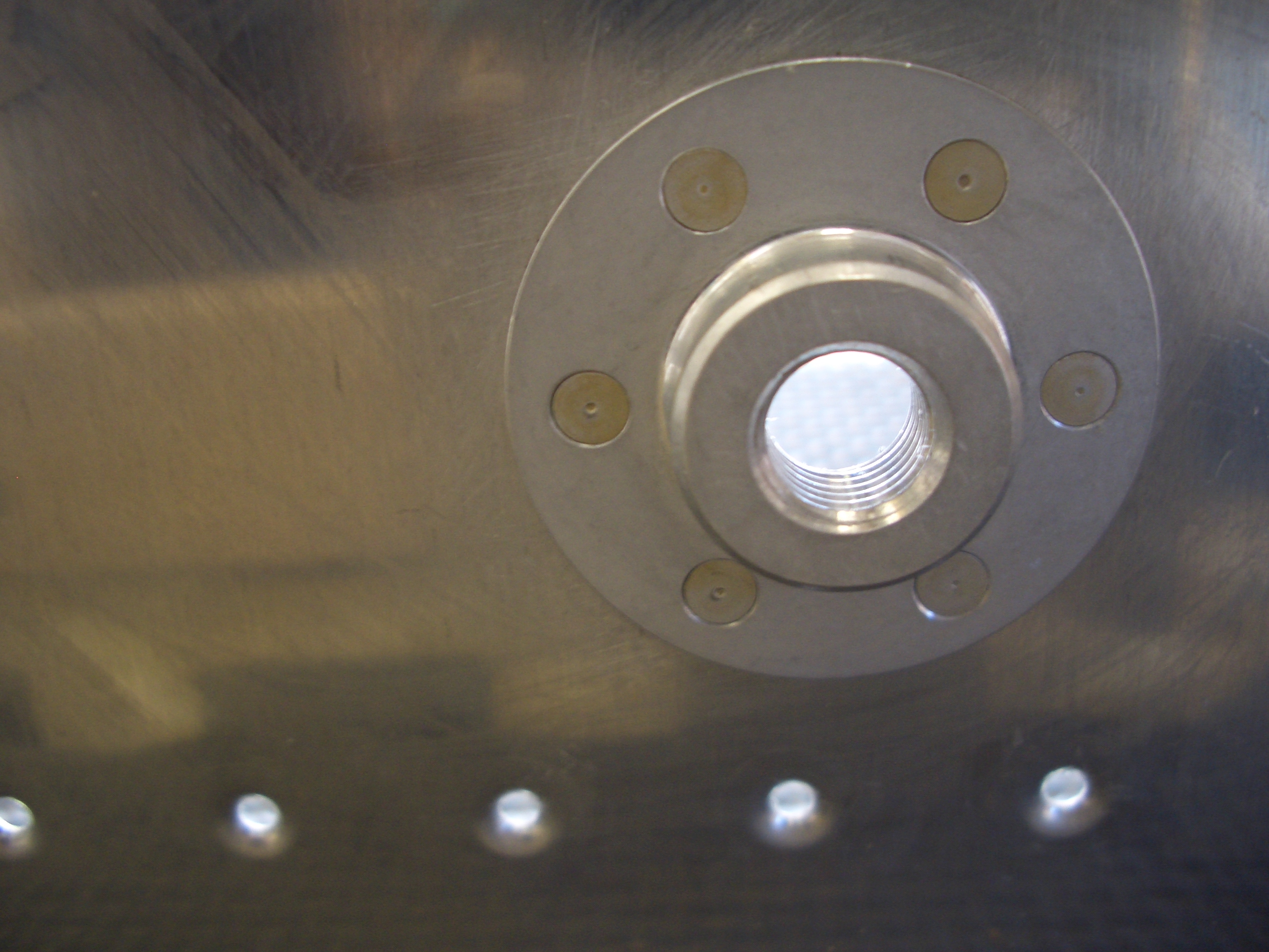
Here is the outside of the fuel drain mount. All of these rivets could be squeezed.

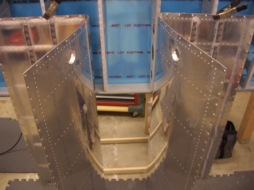
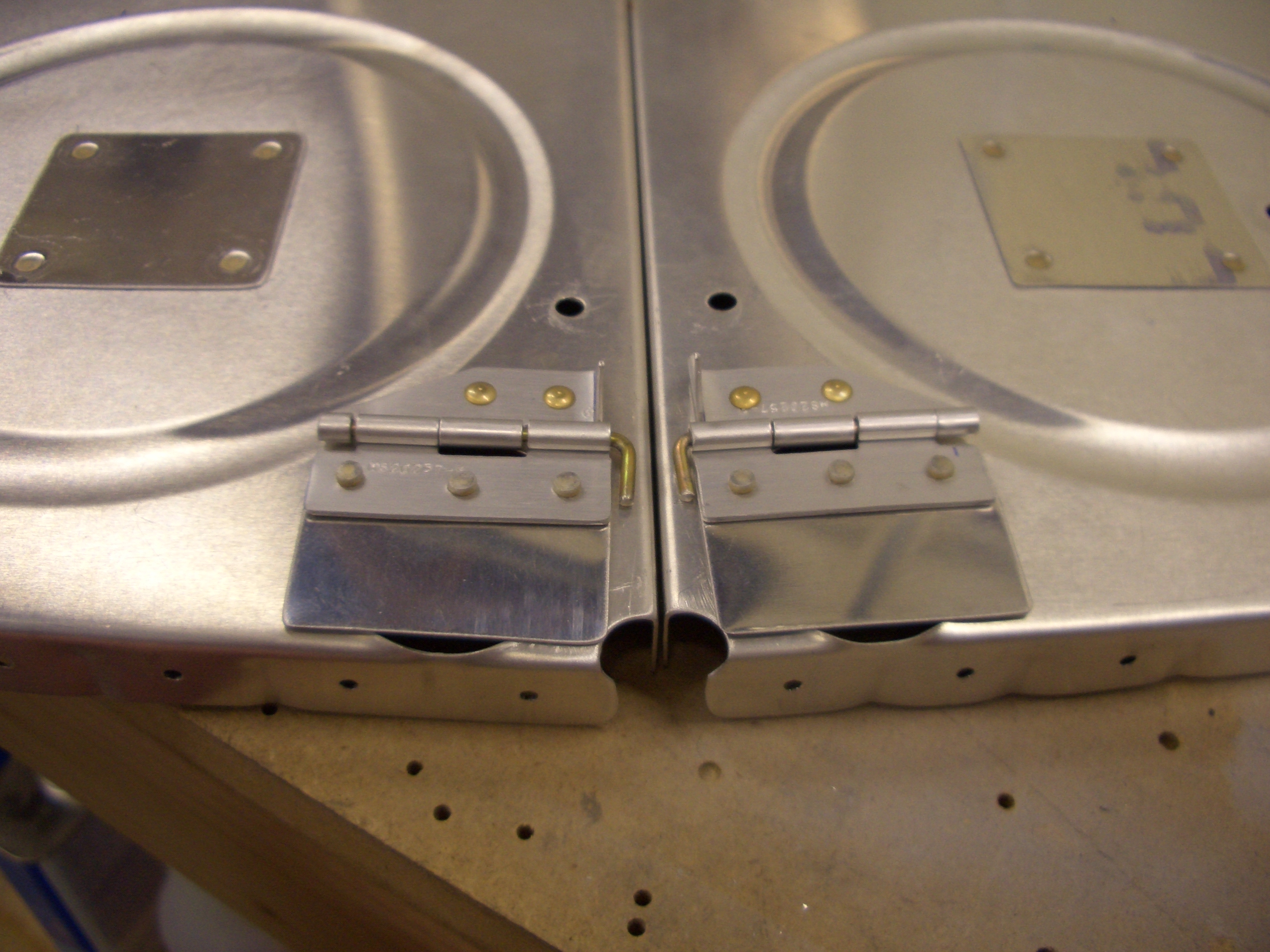
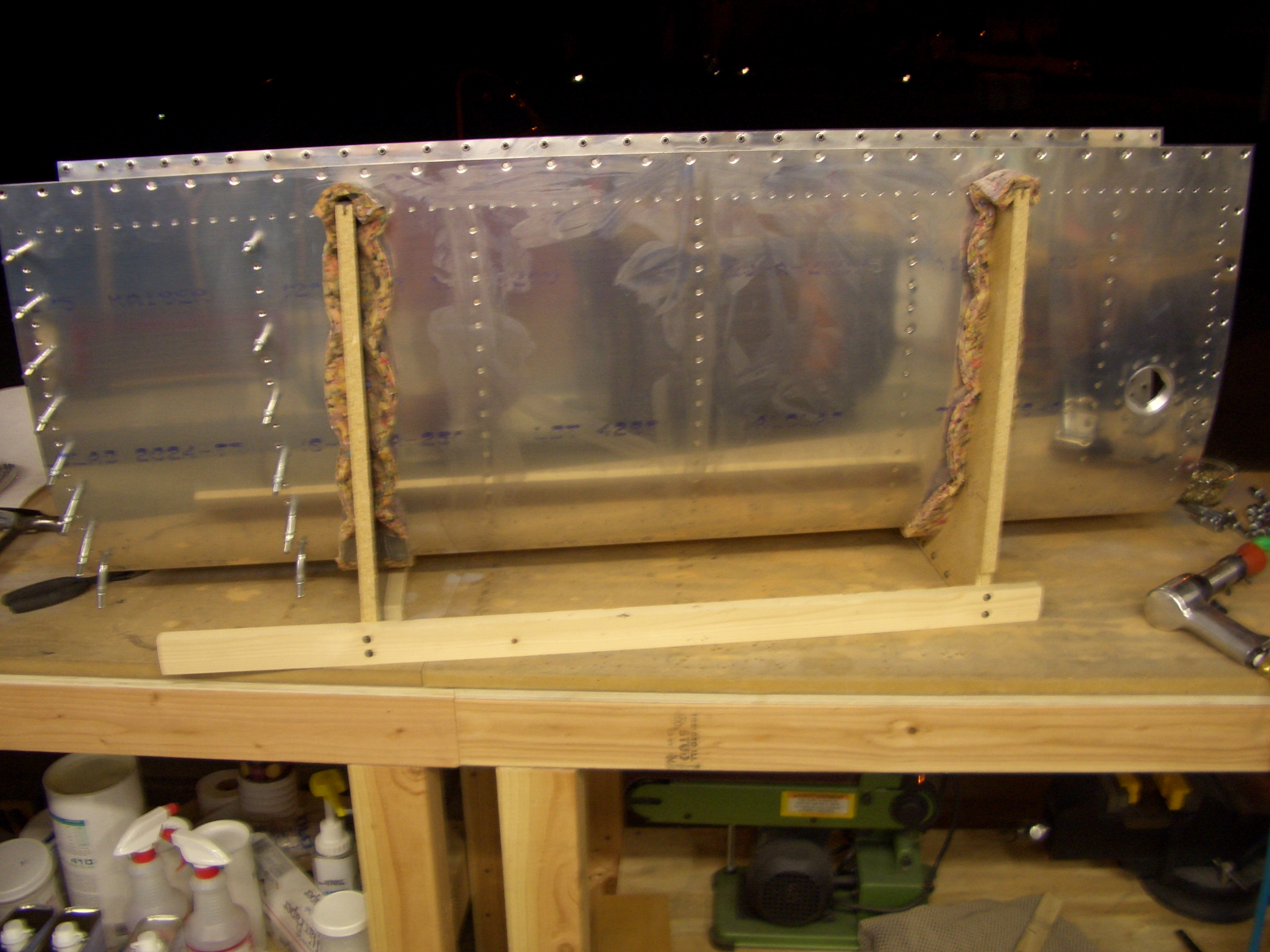
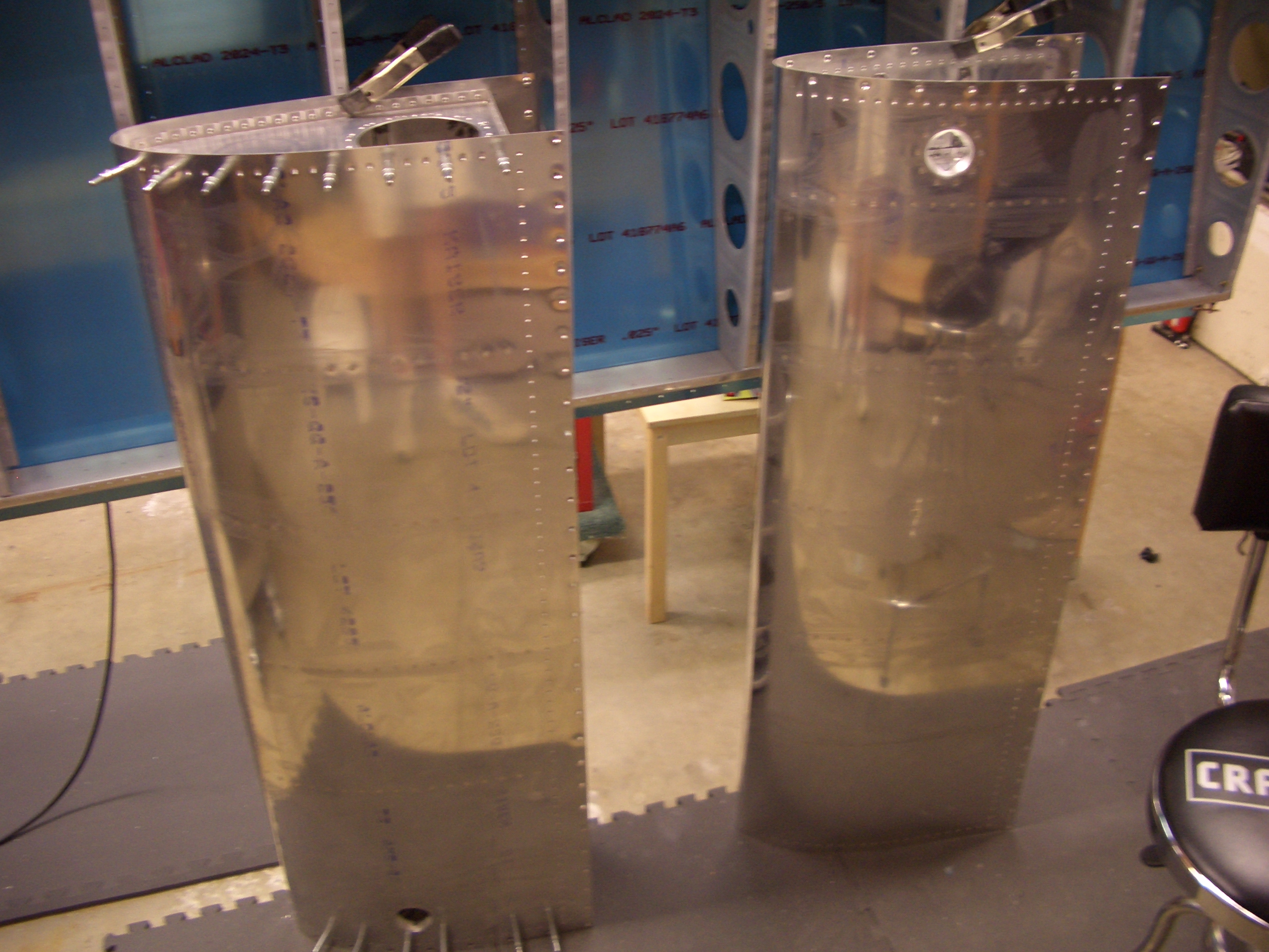
At the end of the day, we had both tank skins with stiffeners, drains, and filler necks in place.