Attached Empennage

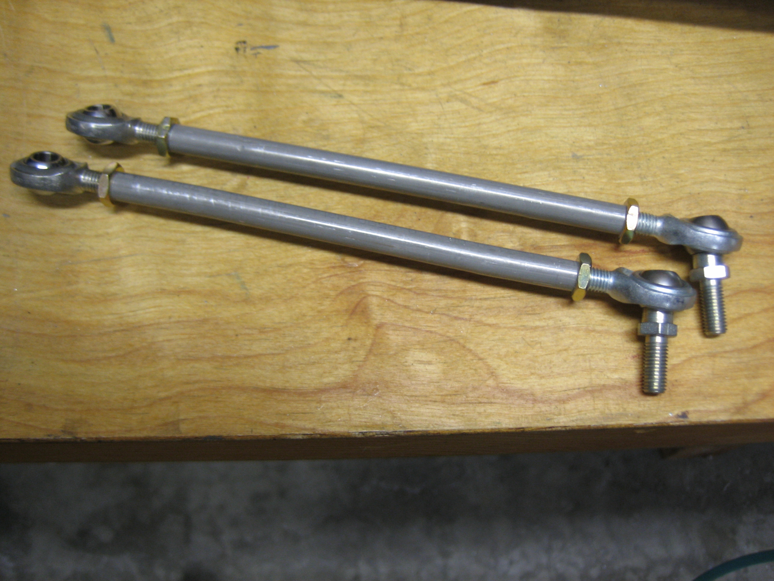
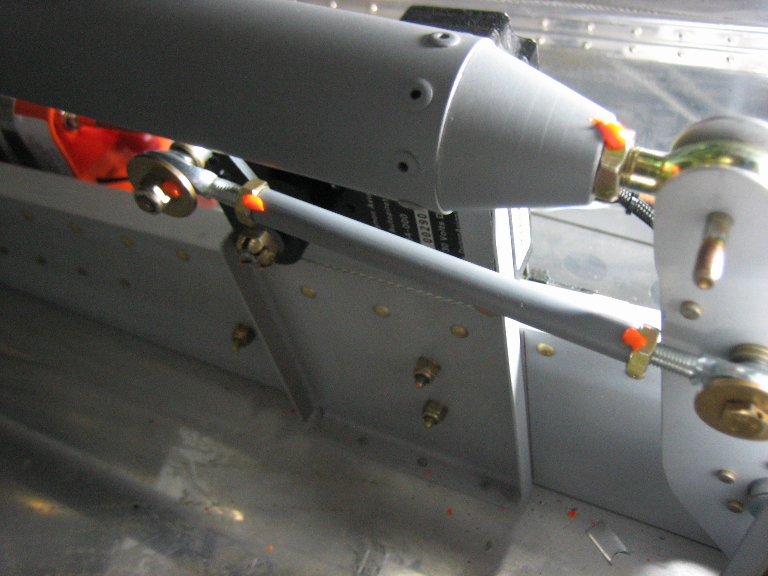
My goal for today was to get the empennage attached to the fuselage.  I came out to the garage early and fabricated the rear elevator pushrod since I’d need it to hook up the elevators.

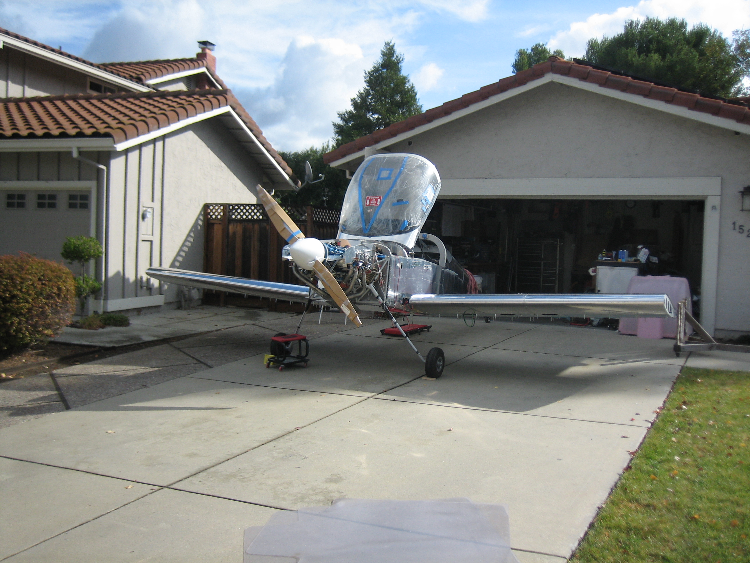
My buddy Andre dropped by to help me attach the empennage.  I then pulled the plane most of the way out of the garage to make some more room, then placed the horizontal stabilizer in place.  The forward spar sits on a couple of spacers that Andre fabricated for me.

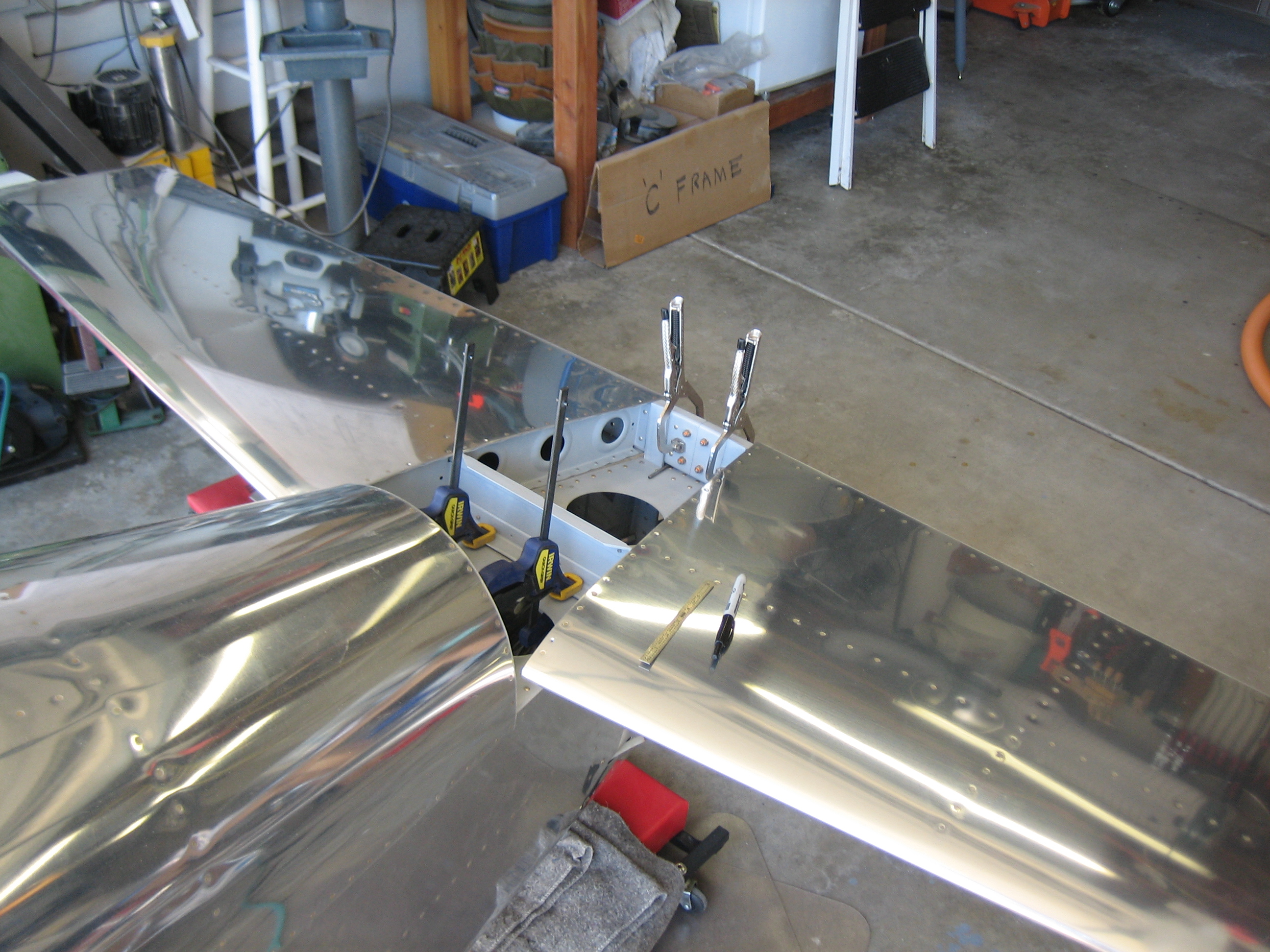
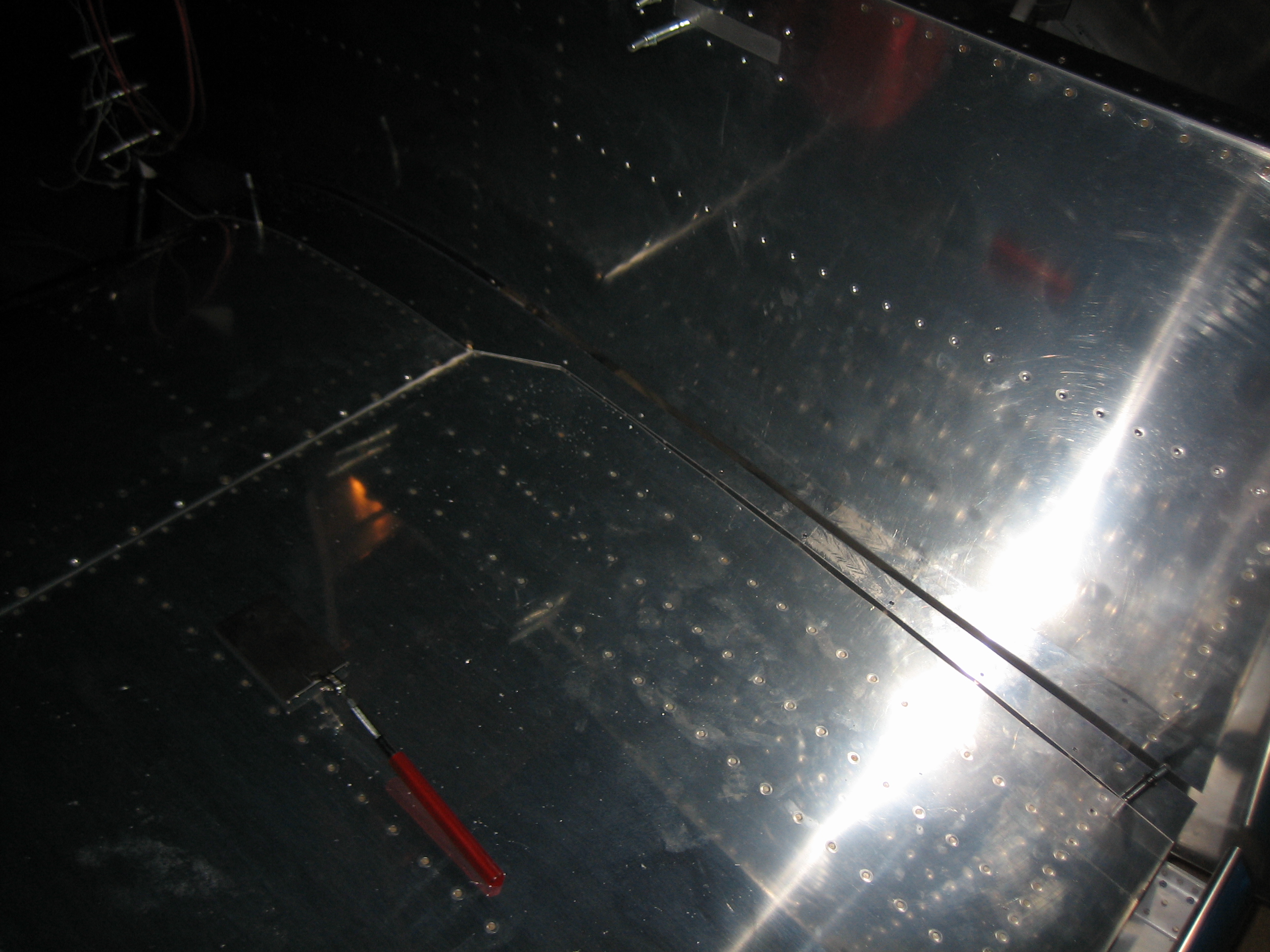
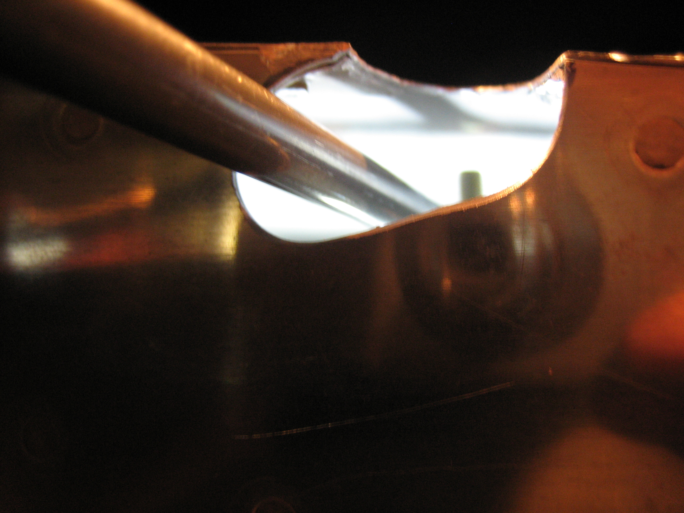
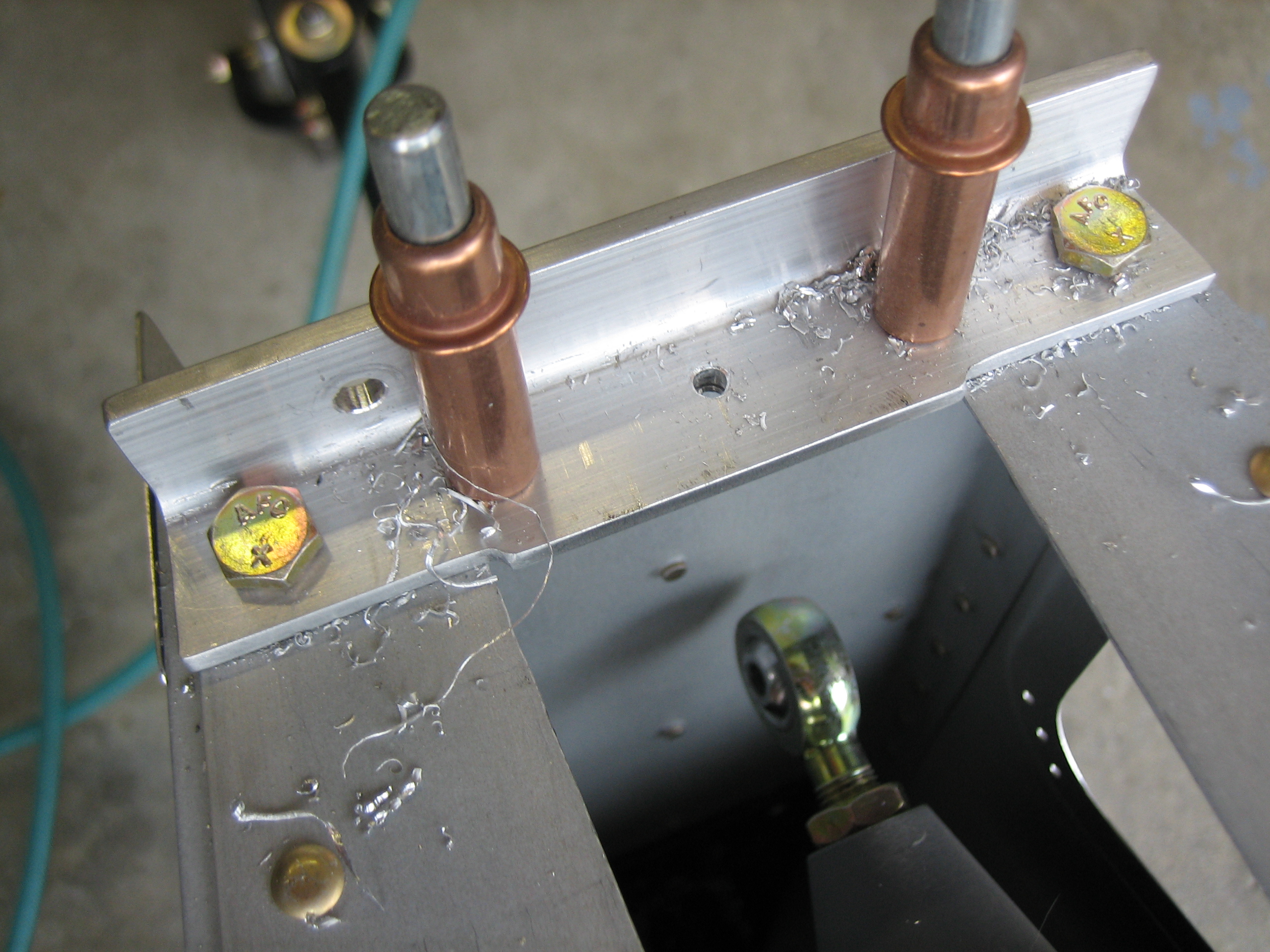
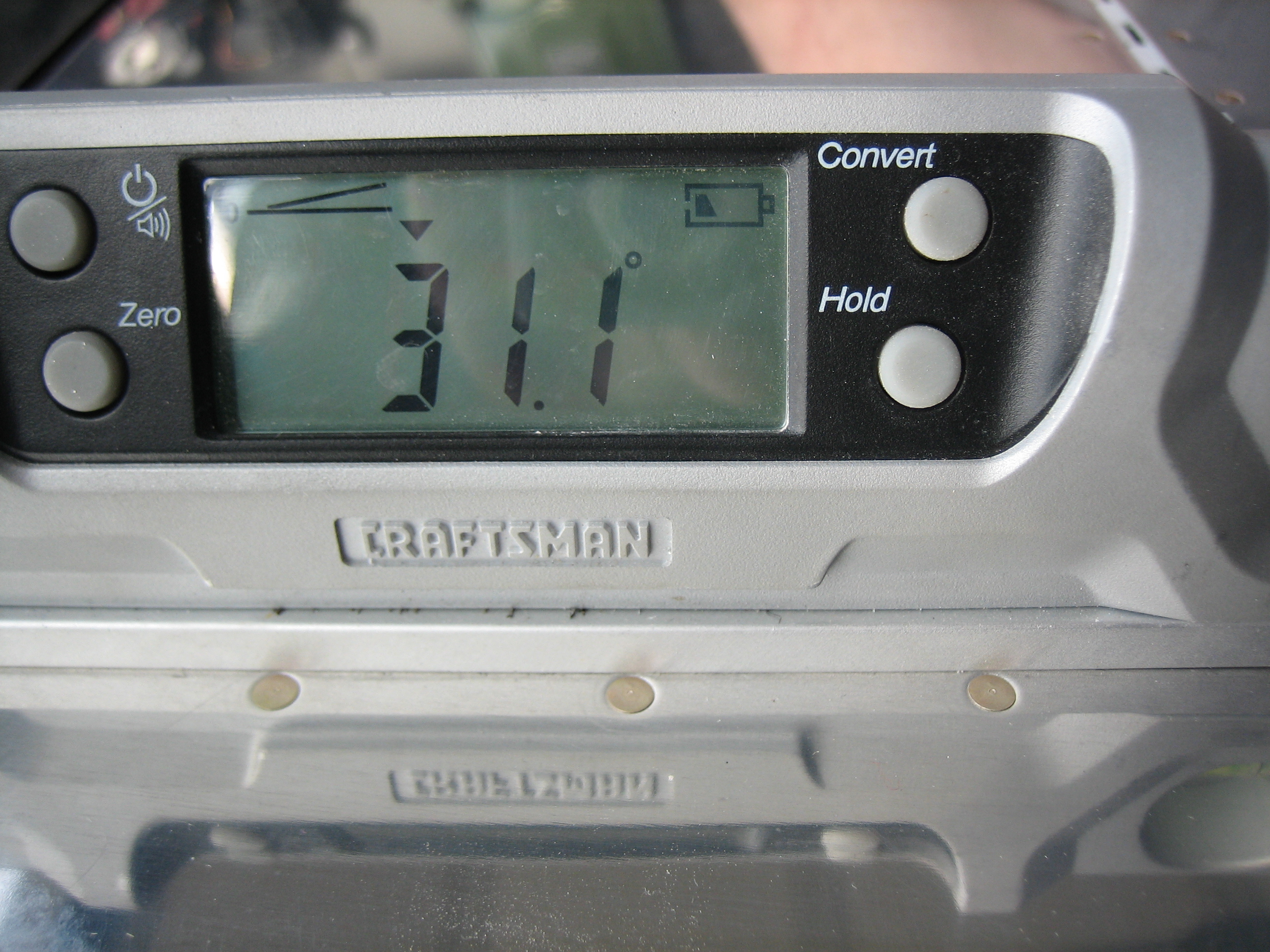
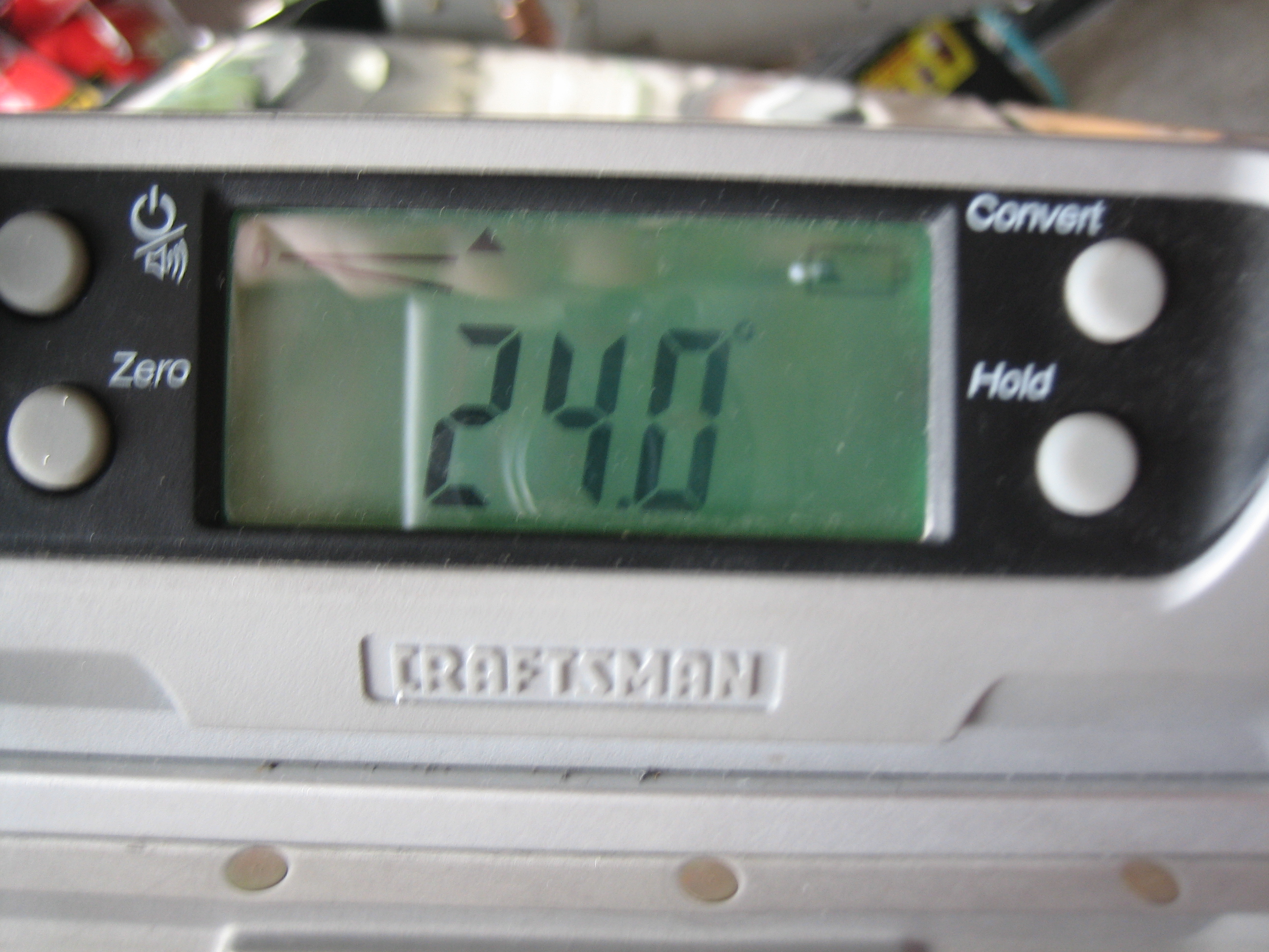
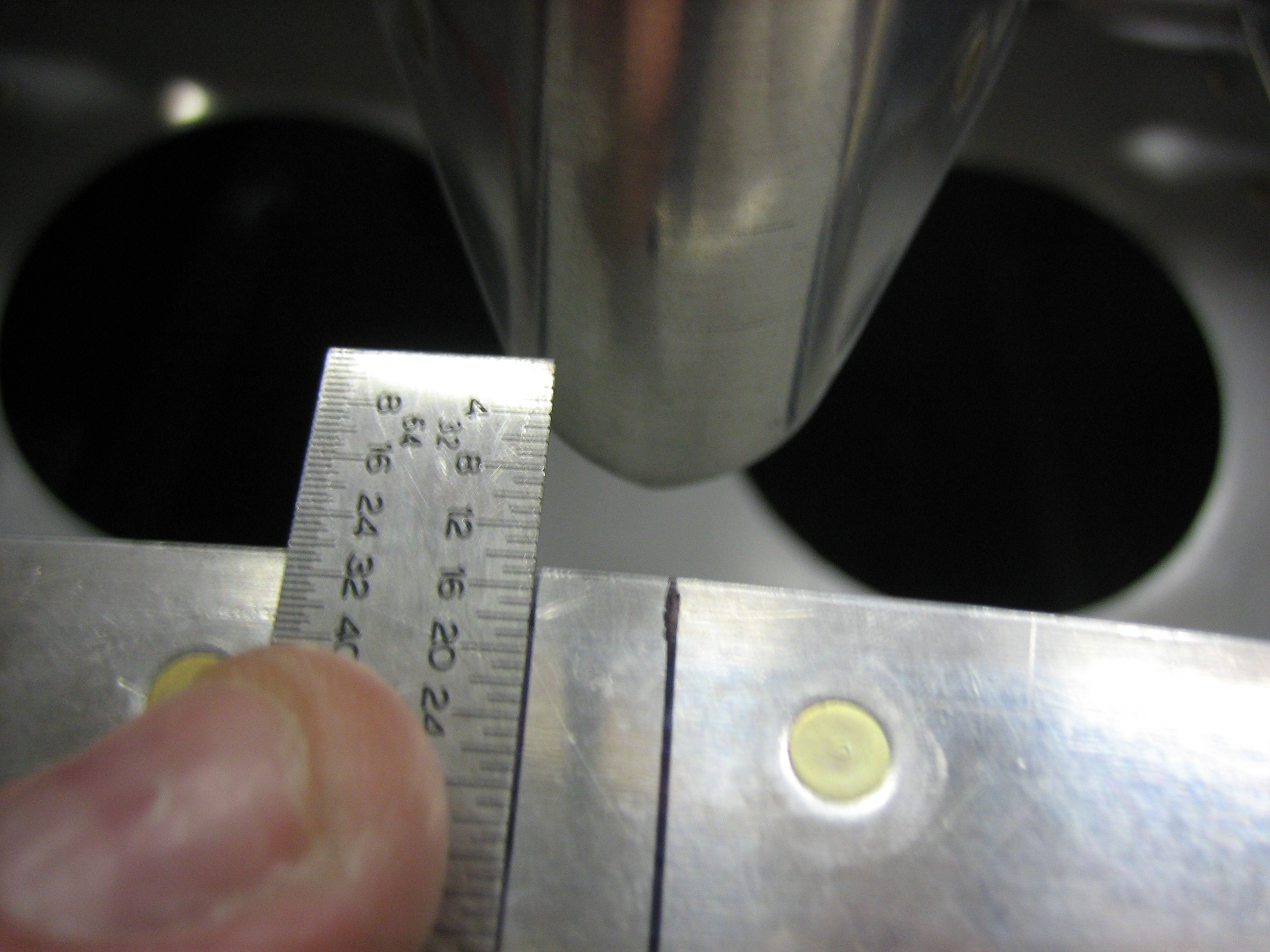
The rear spar sits on a couple of 3/16″ drill bits to space it up off the deck.  I measured the tooling holes to ensure that the stabilizer incidence is 0º.

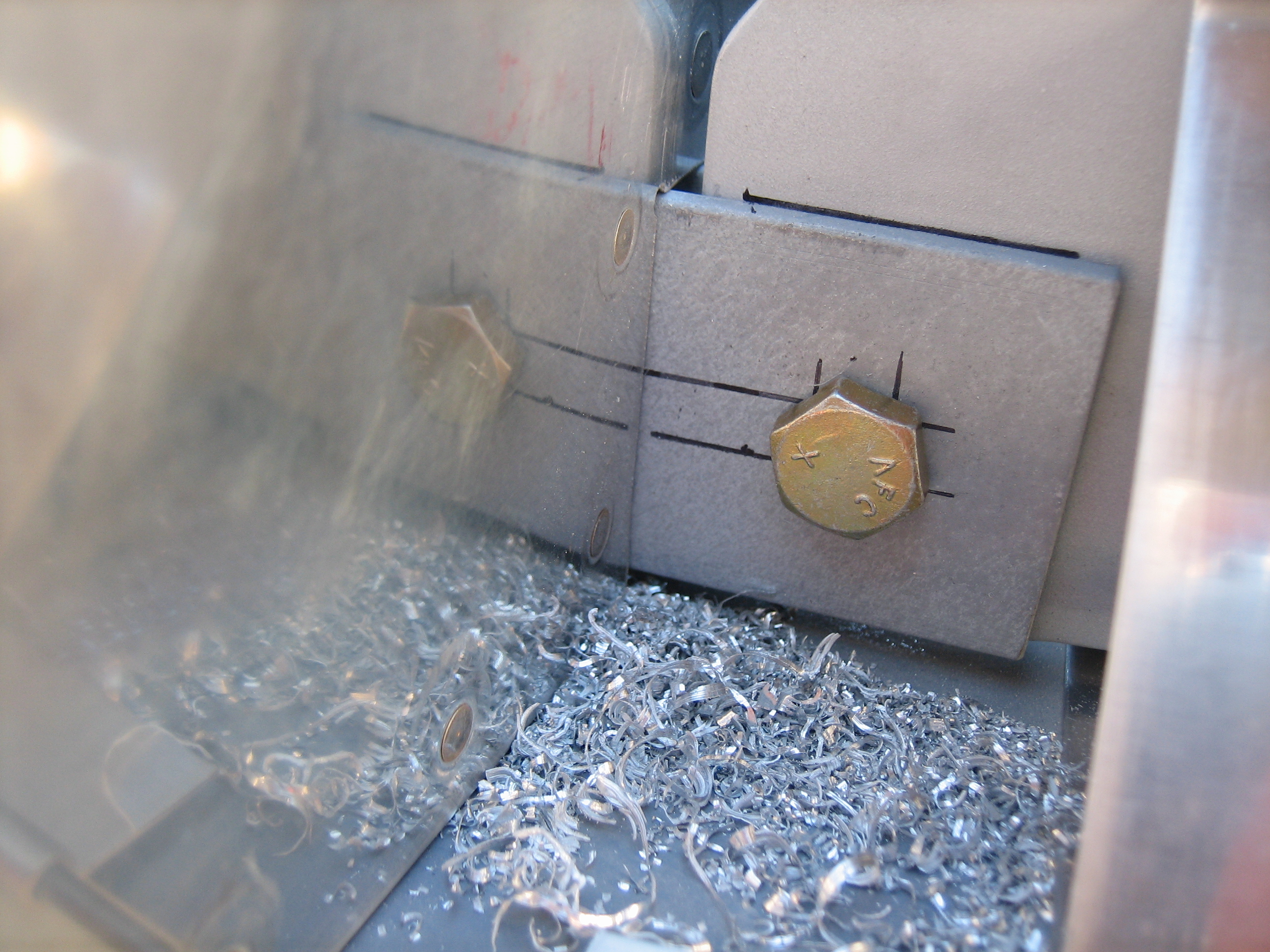
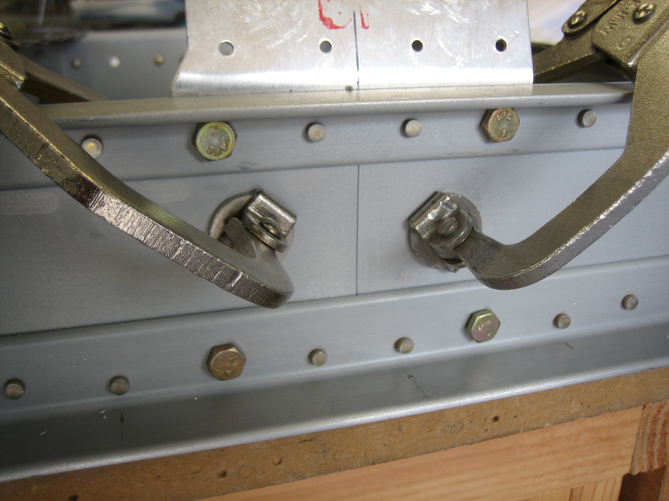
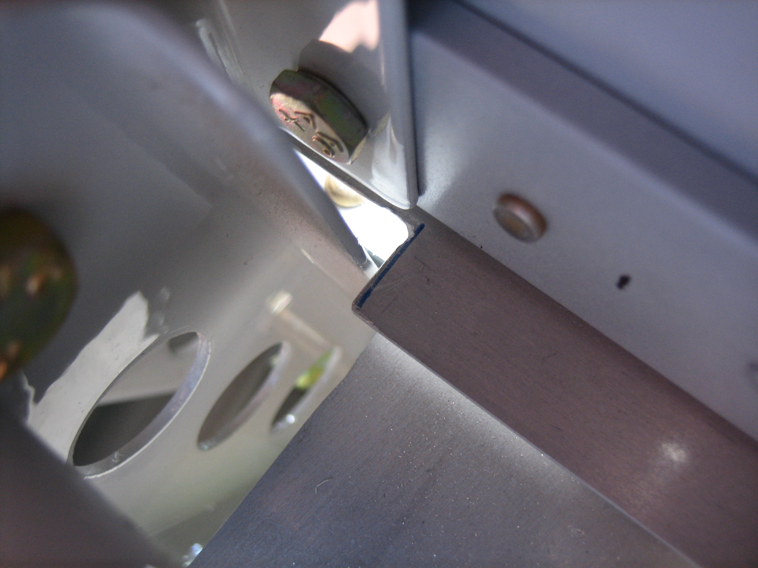
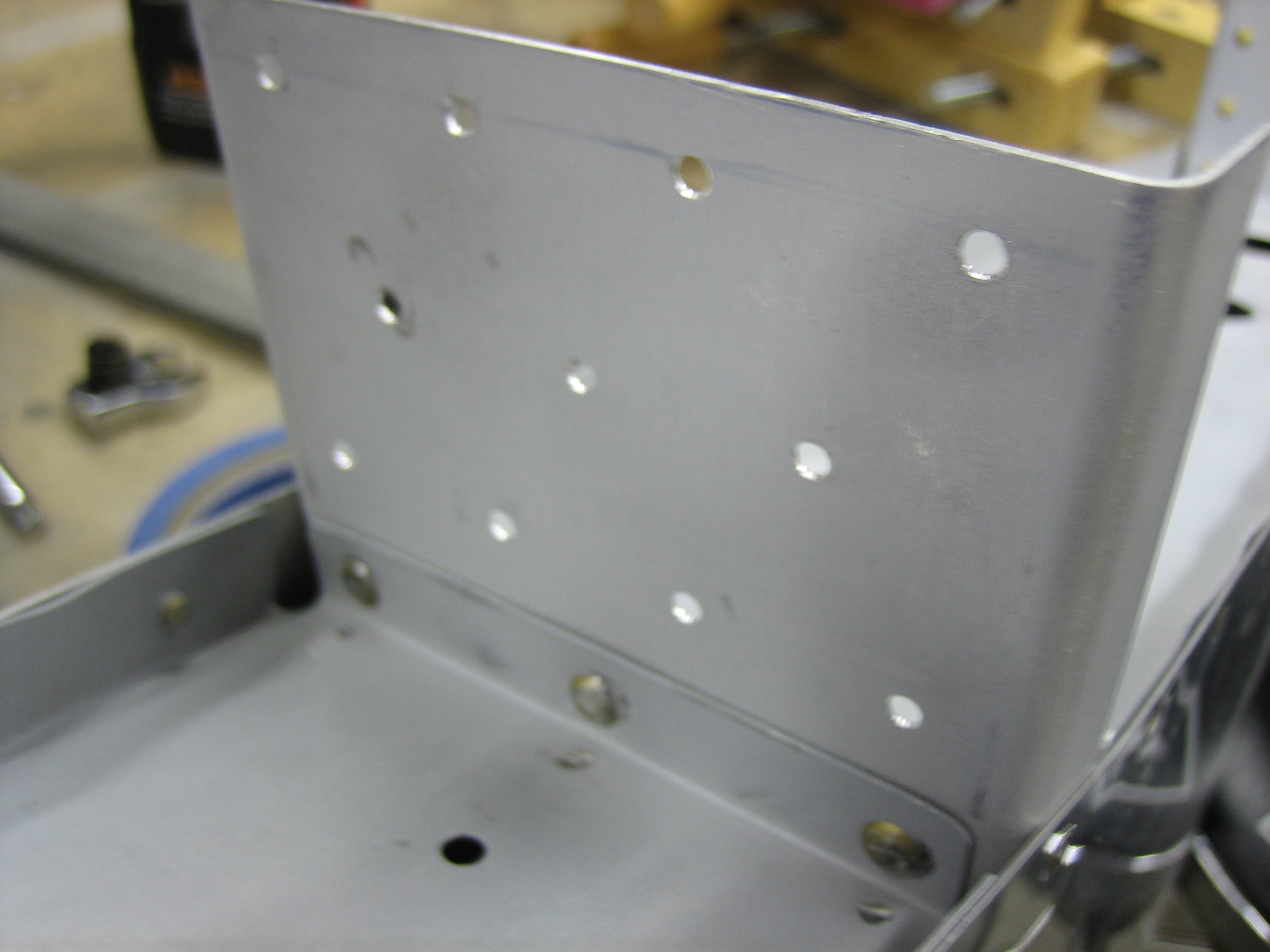
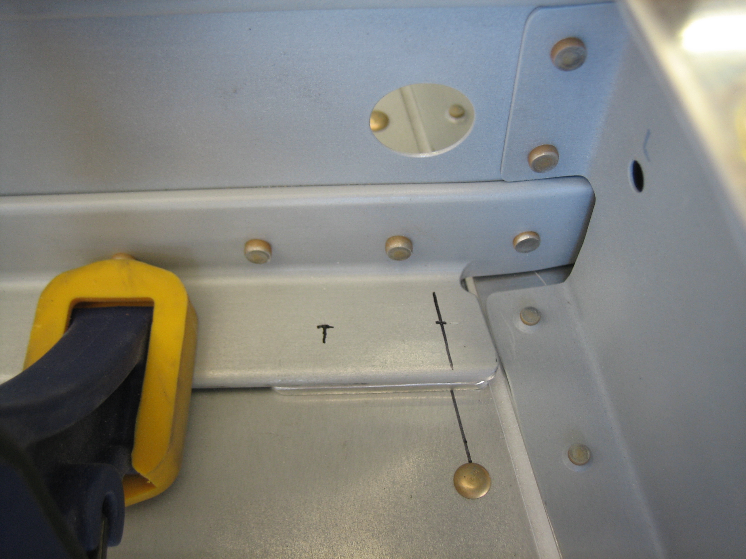
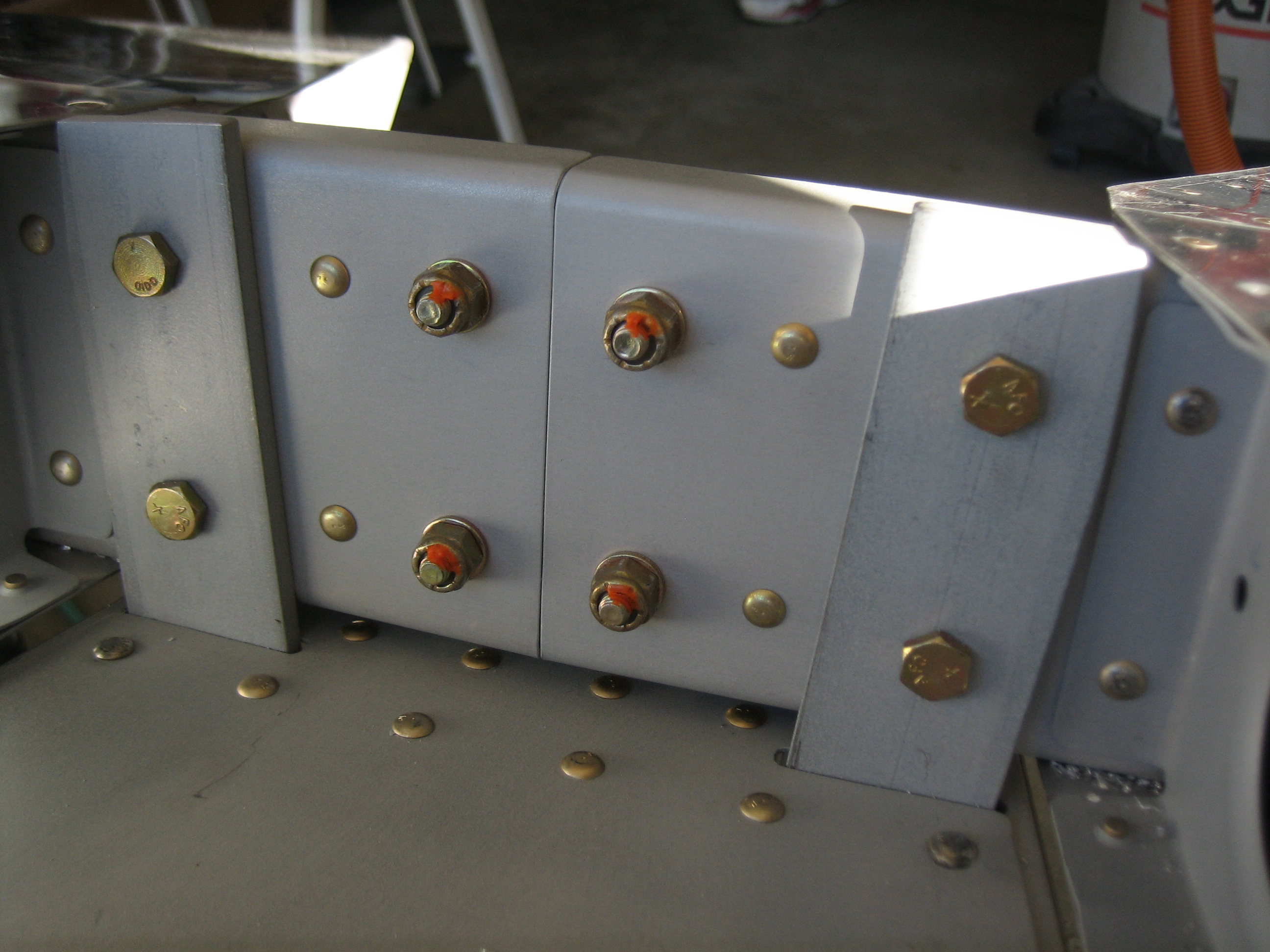
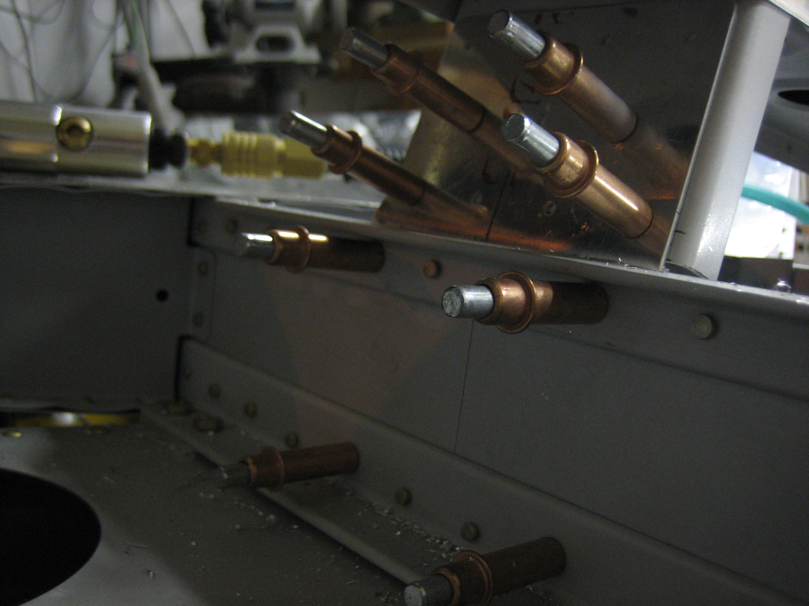
I then laid out the holes that will be drilled in the forward spar.  The outer holes (right in this picture) penetrate this angle, the spacer, the aft deck, the longeron, and the cross brace.  There’s over 1/2″ of material here that is bolted together.

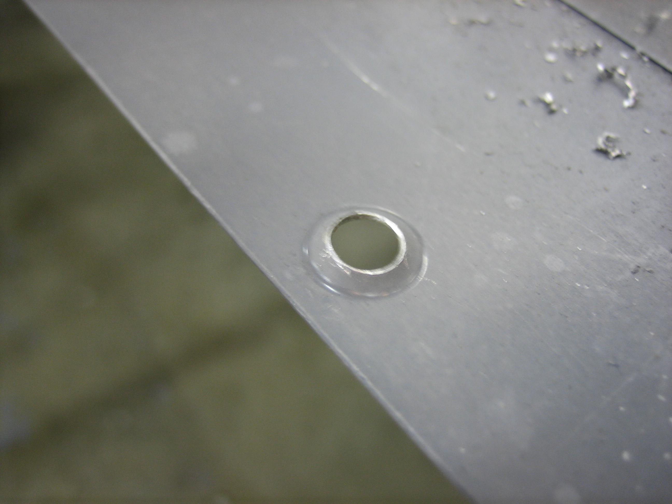
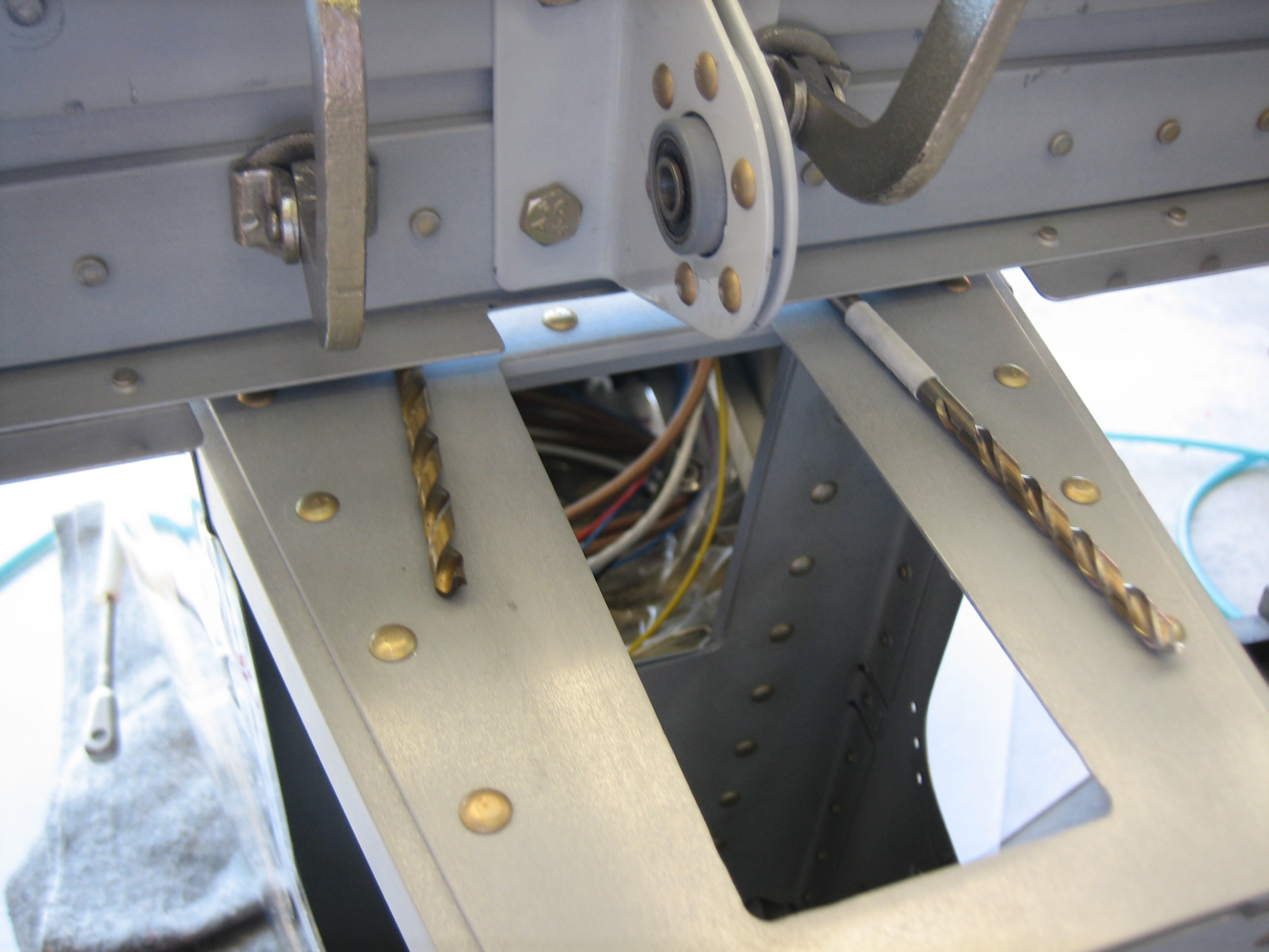
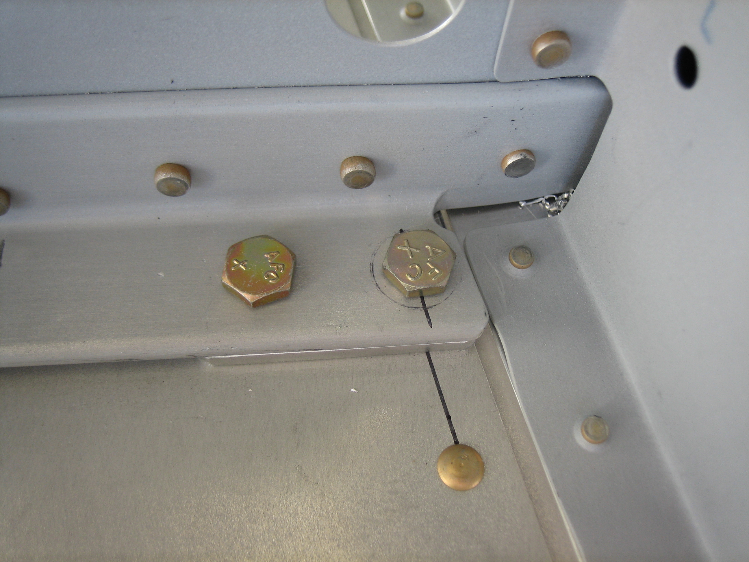
I then drilled the holes.  The outer ones can be drilled and reamed straight on, but I had to use the angle drill to do the inner ones.

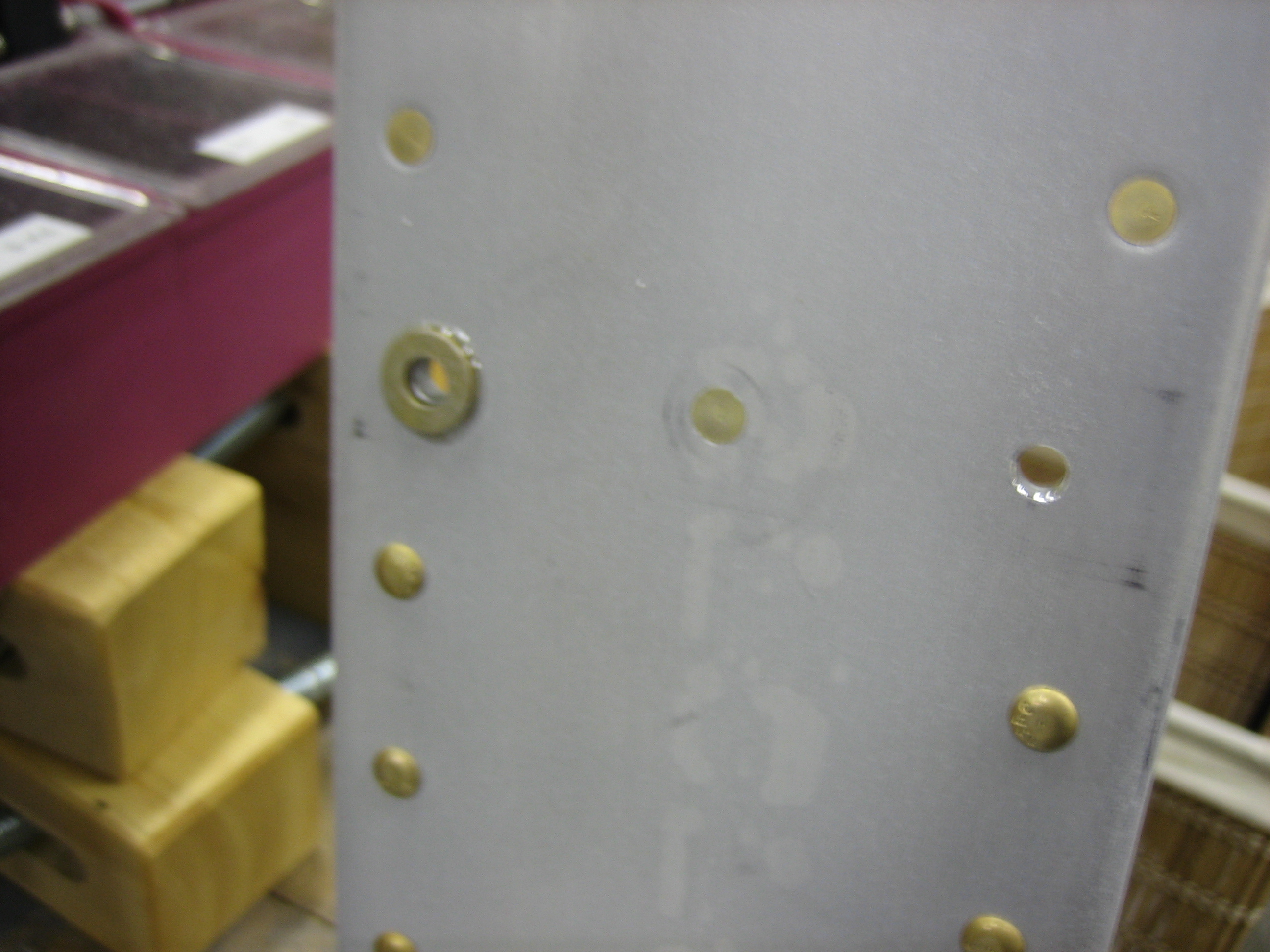
I then laid out and drilled the holes through the aft spar and attach bars.

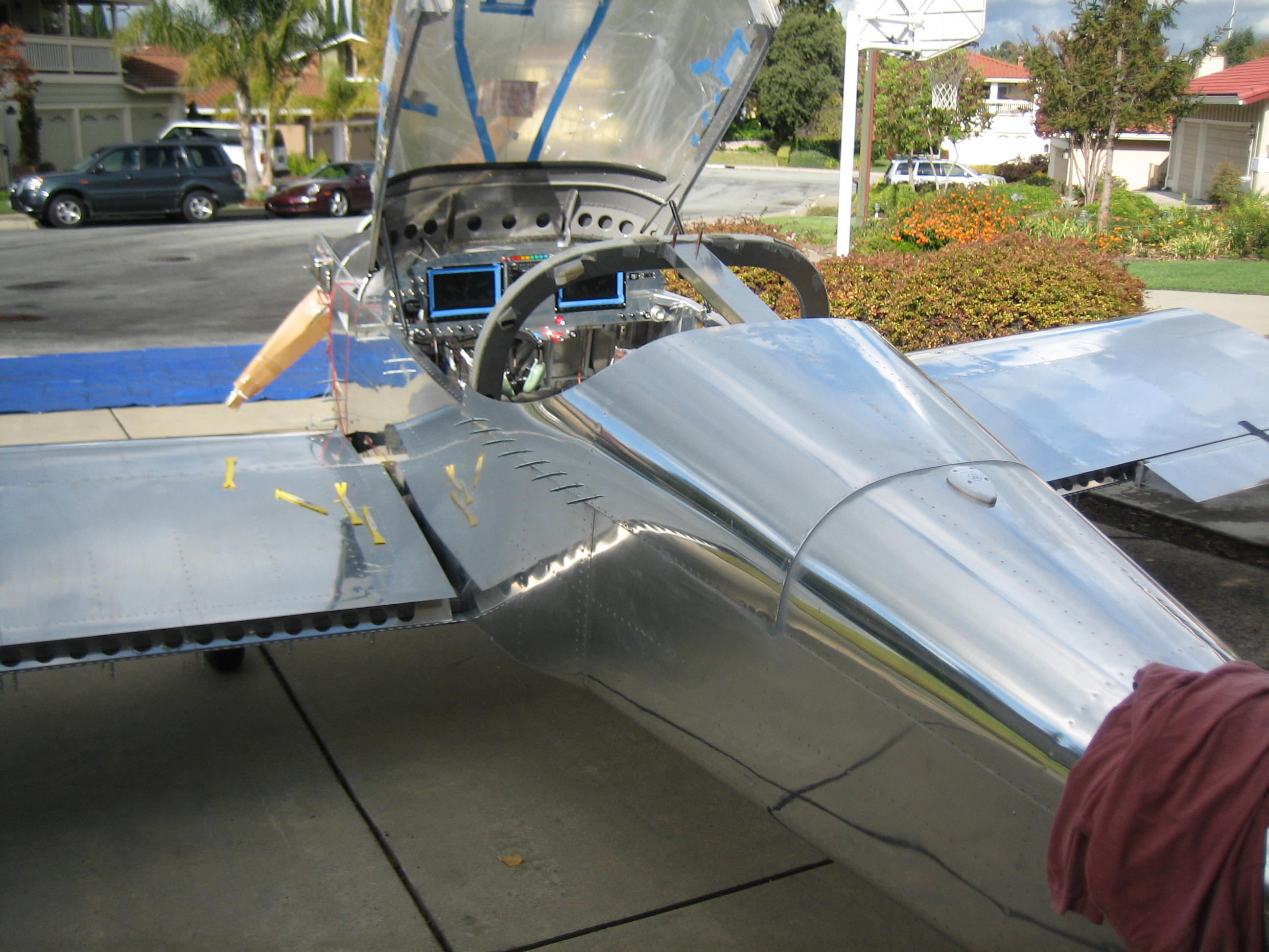
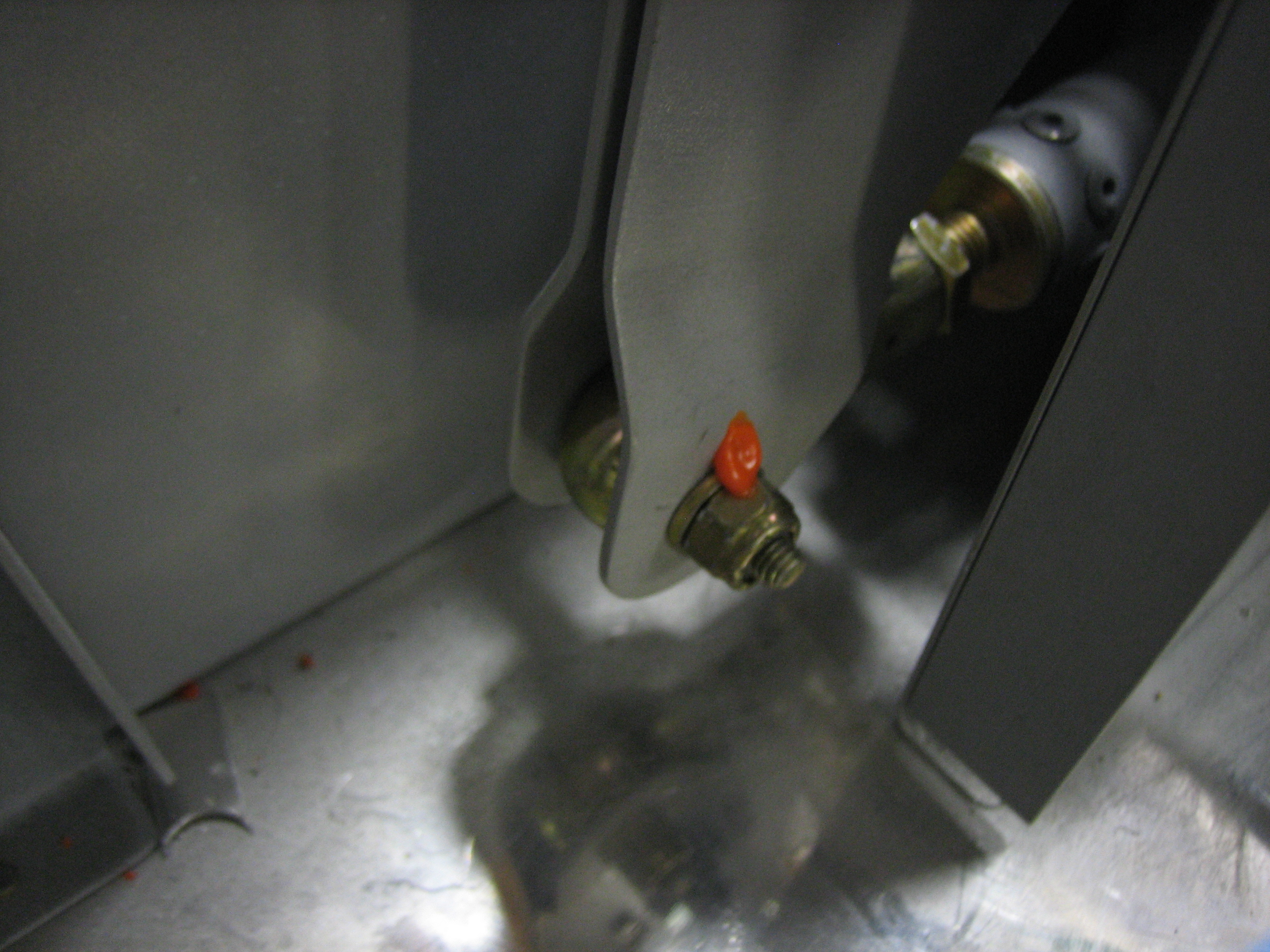
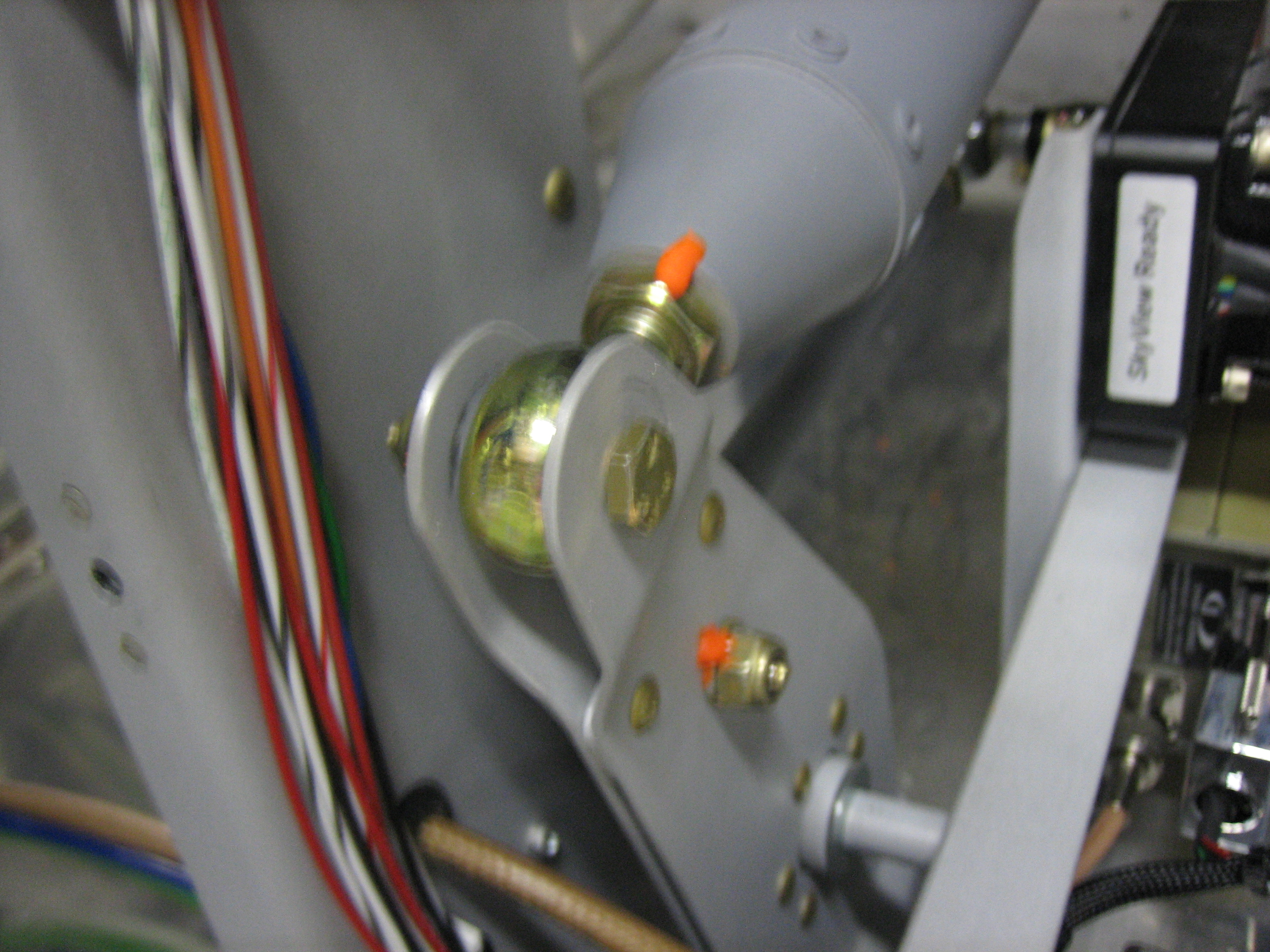
We then hung the elevators and drilled the pushrod attach hole.  Andre then helped me temporarily attach the vertical stabilizer.

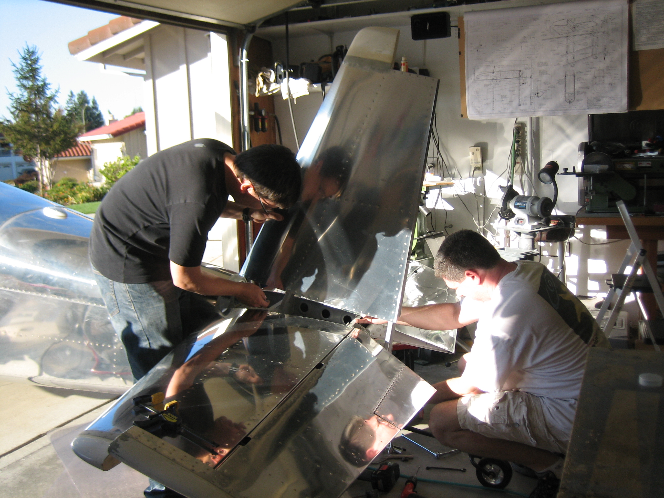
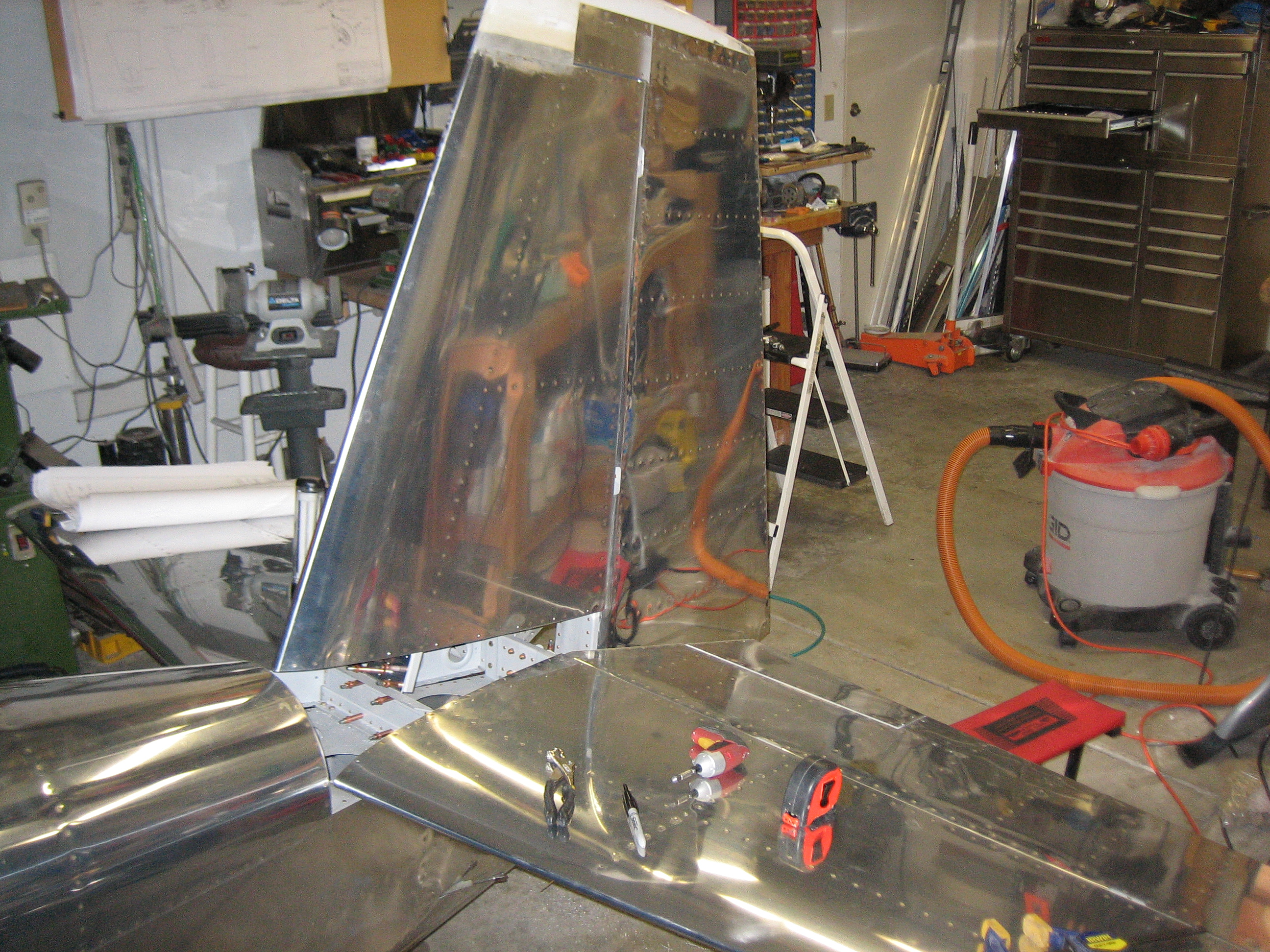
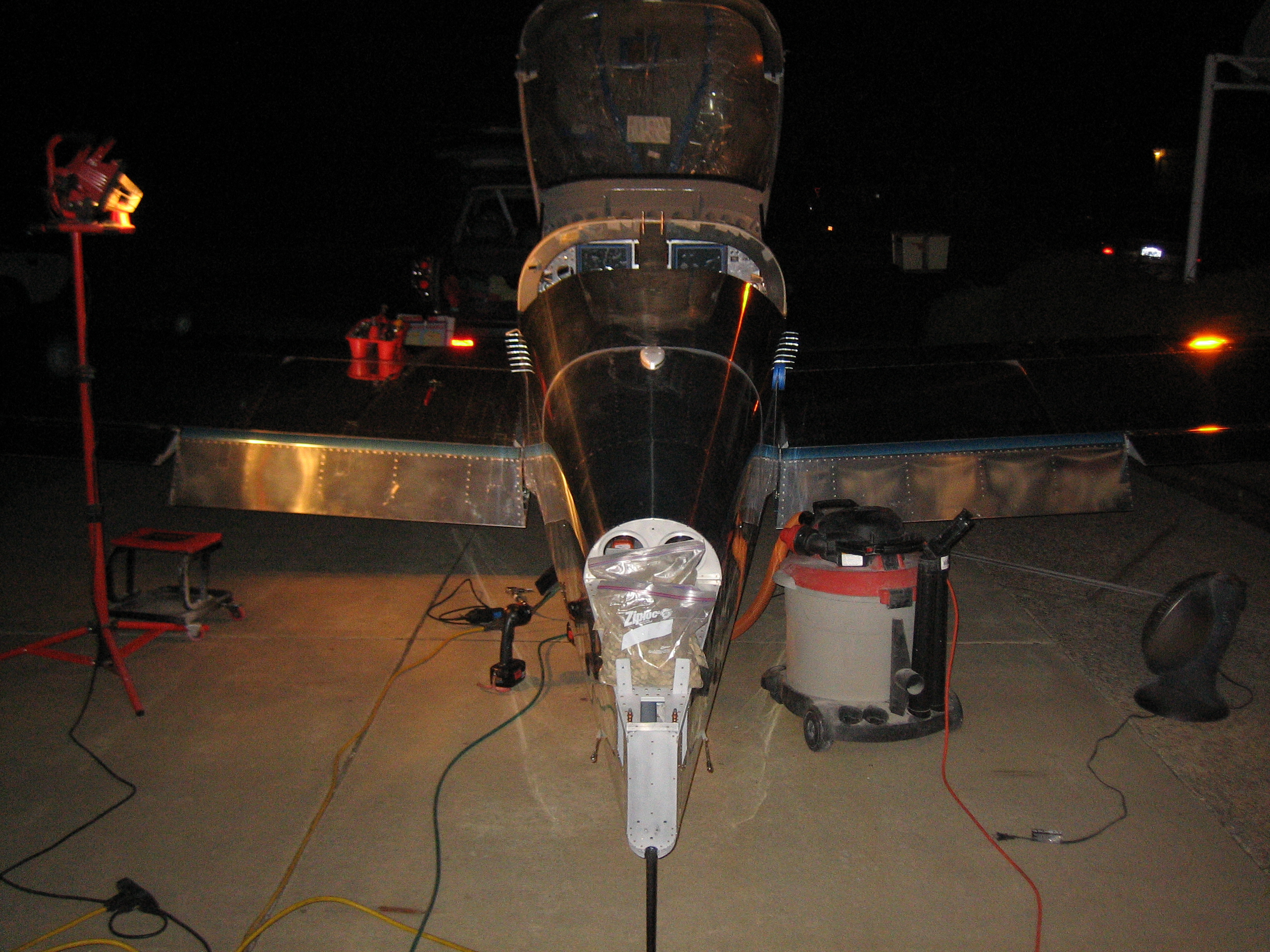
Jenn came out a little later and snapped this picture of me working on positioning the vertical stabilizer.

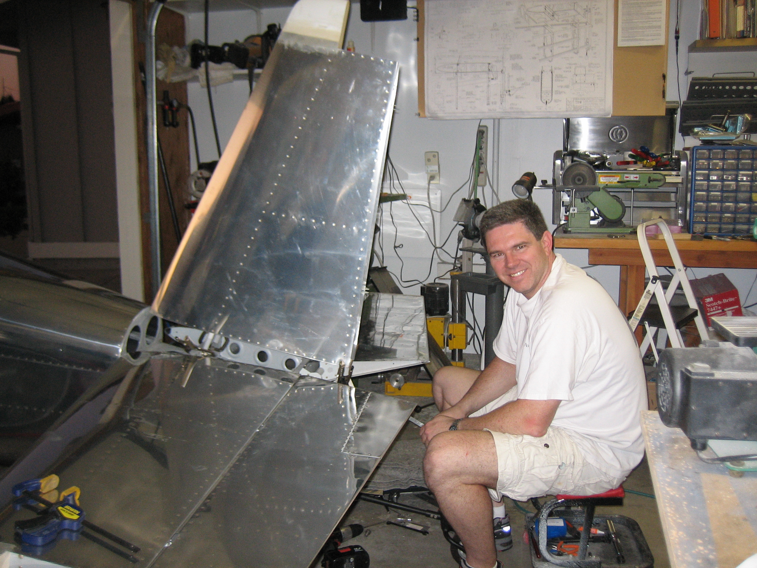
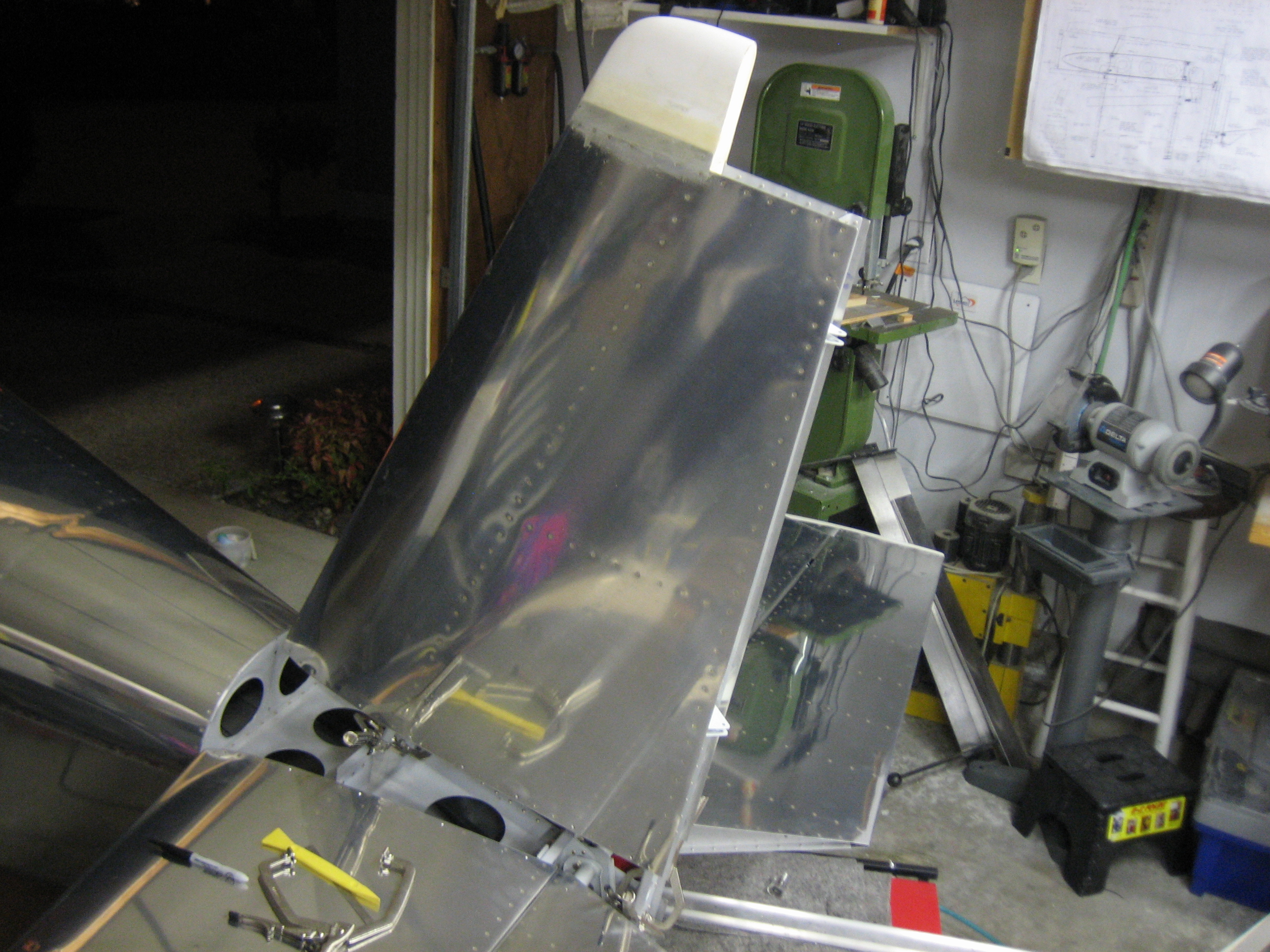
Getting the vertical stabilizer positioned accurately took much longer than the horizontal stabilizer.  The stabilizer has to be perpendicular to the horizontal stabilizer, tipped back at the right angle so that the hinge brackets are in a straight line, then twisted so that the front edge is 1/4″ left of centerline.  It took quite a number of iterations before I had everything nailed.

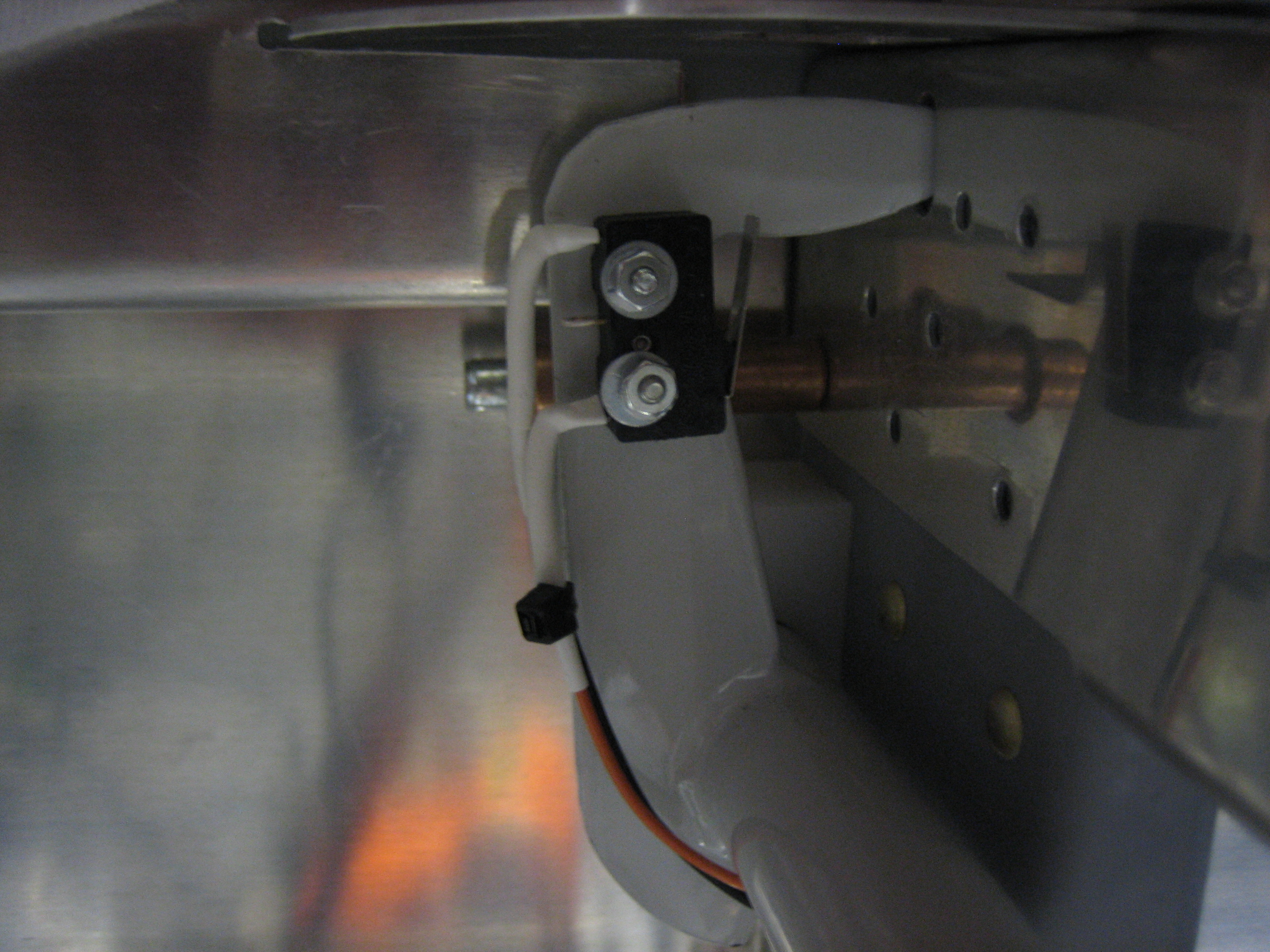
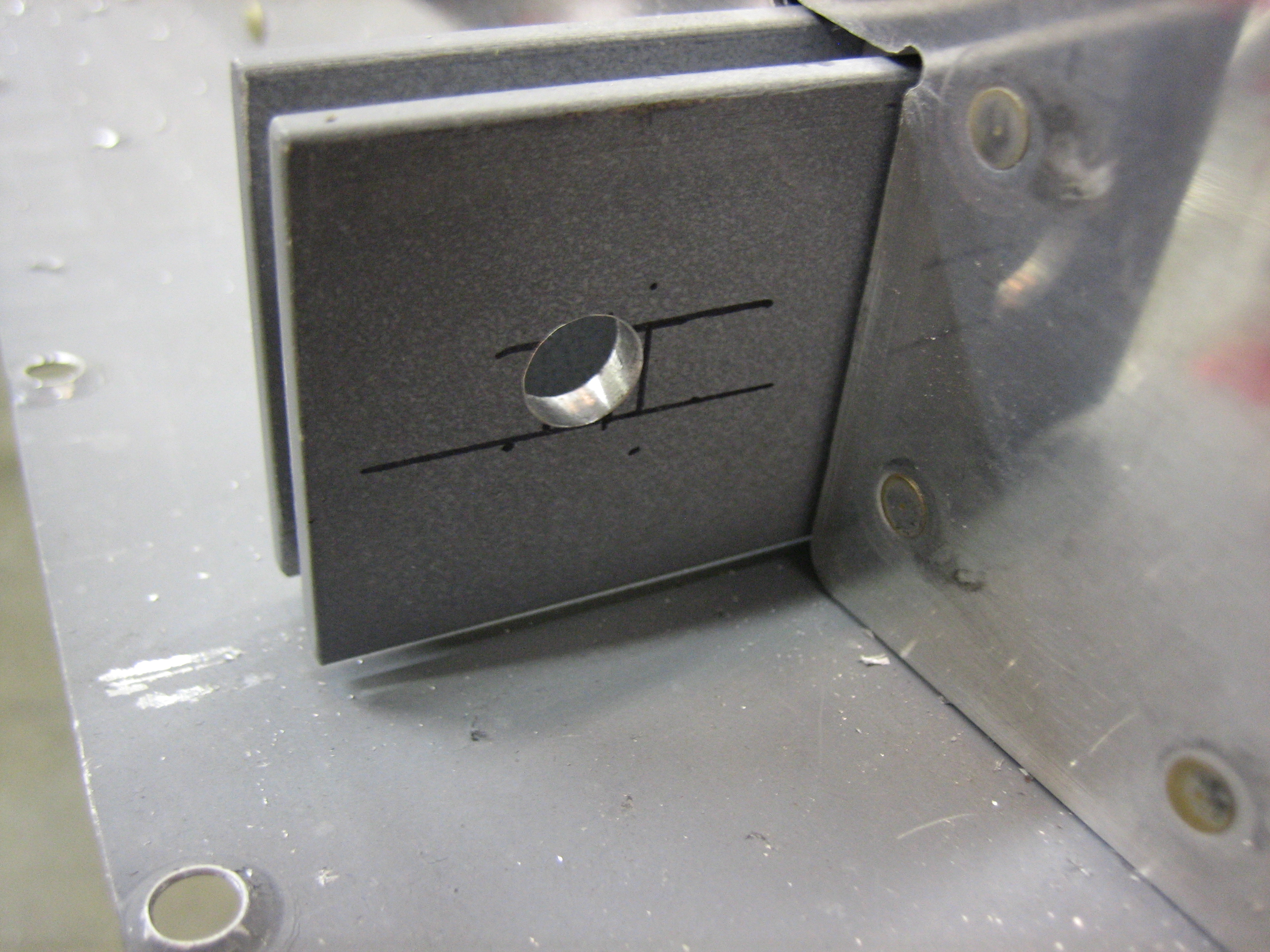
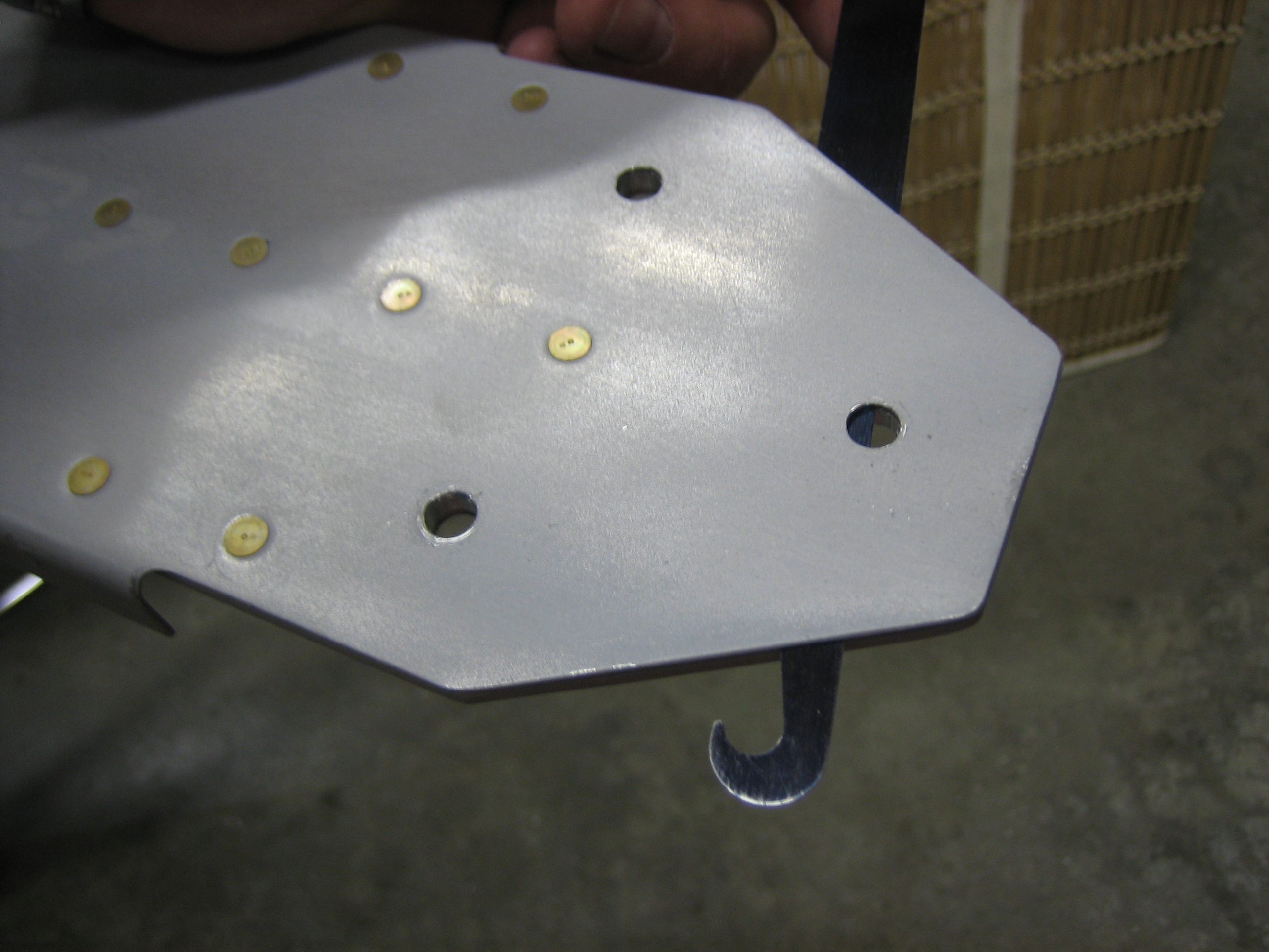
I then fabricated and clamped the up elevator stop.

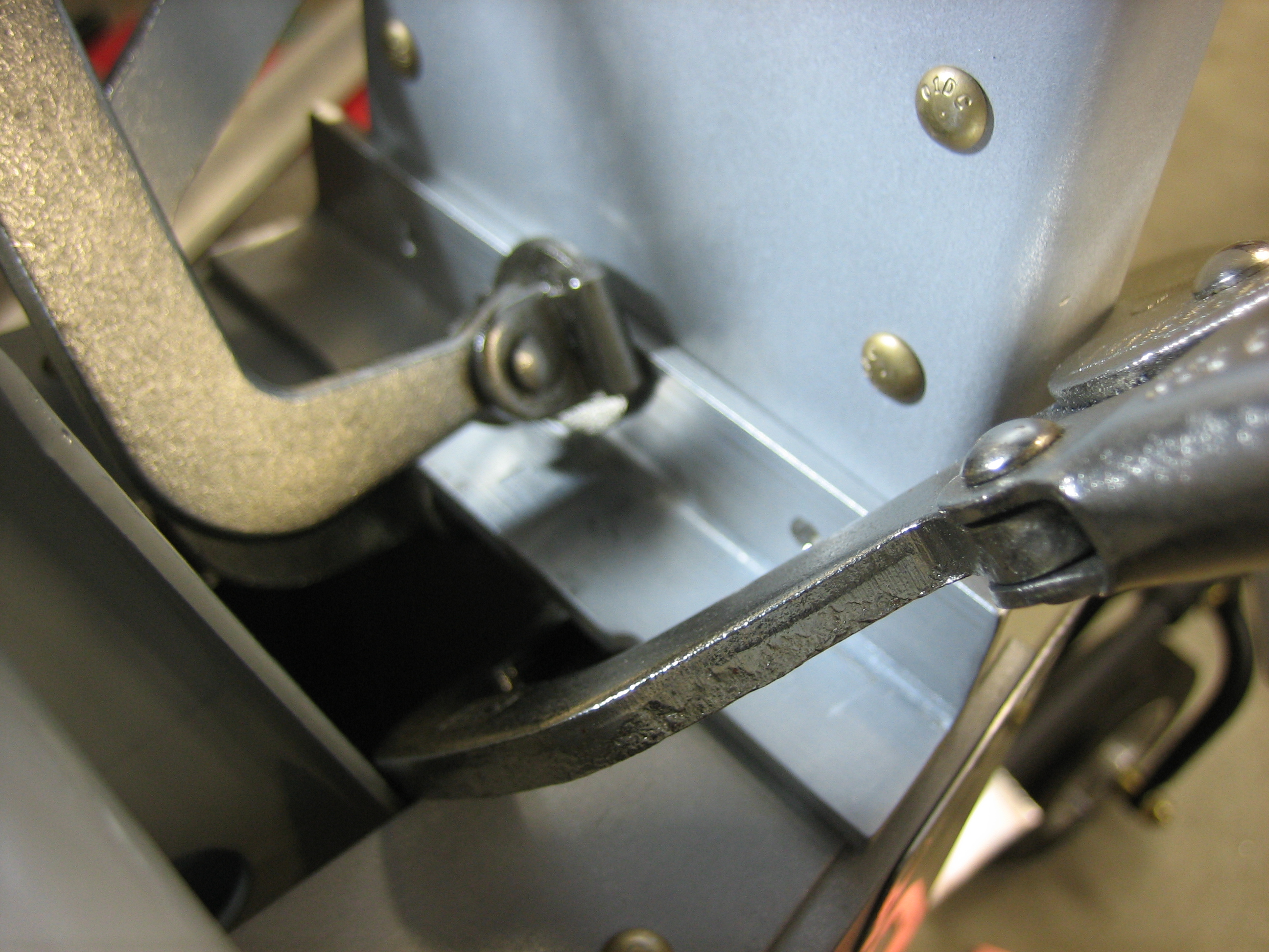
This is then drilled to the vertical stabilizer rear spar.

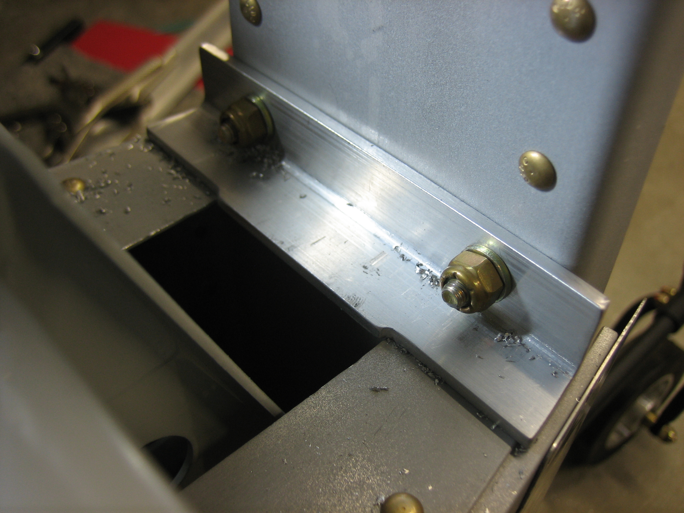
I removed the stop and drilled the remaining holes, then reinstalled it and match drilled the longerons to the stop.

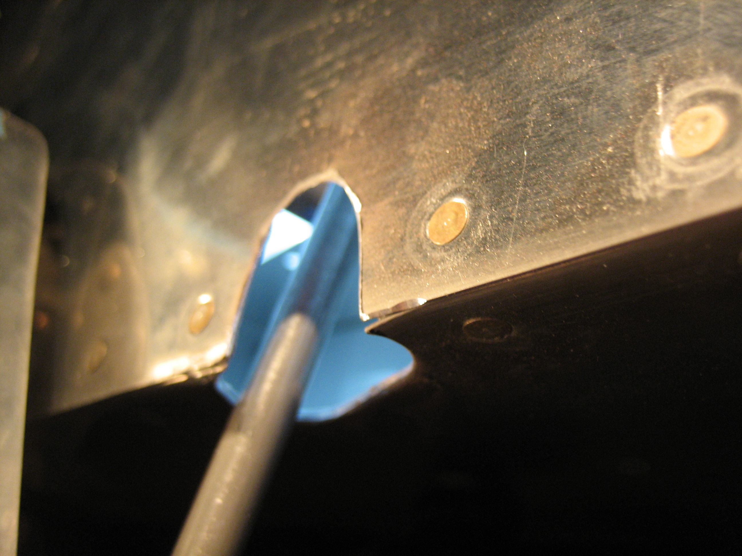
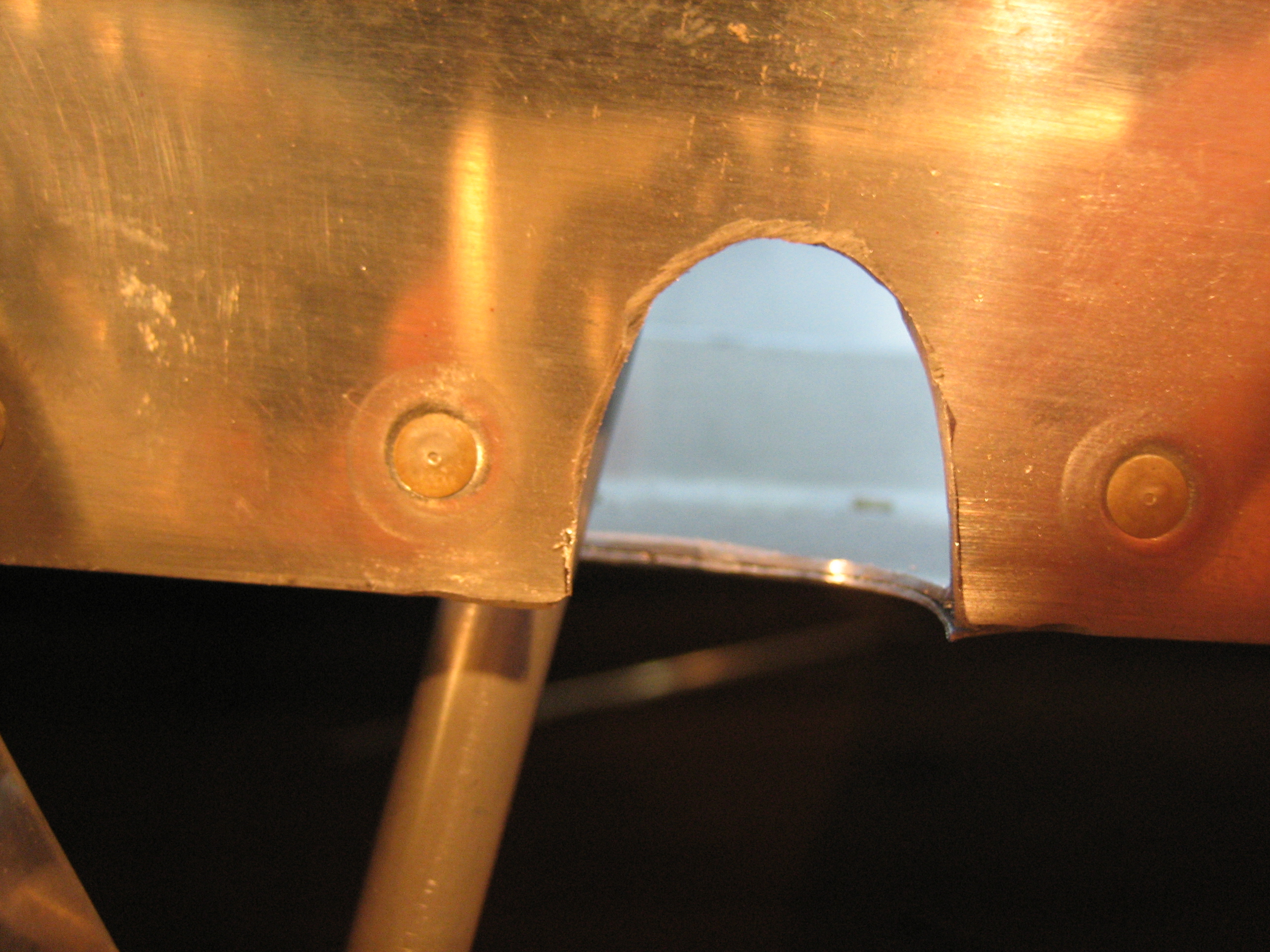
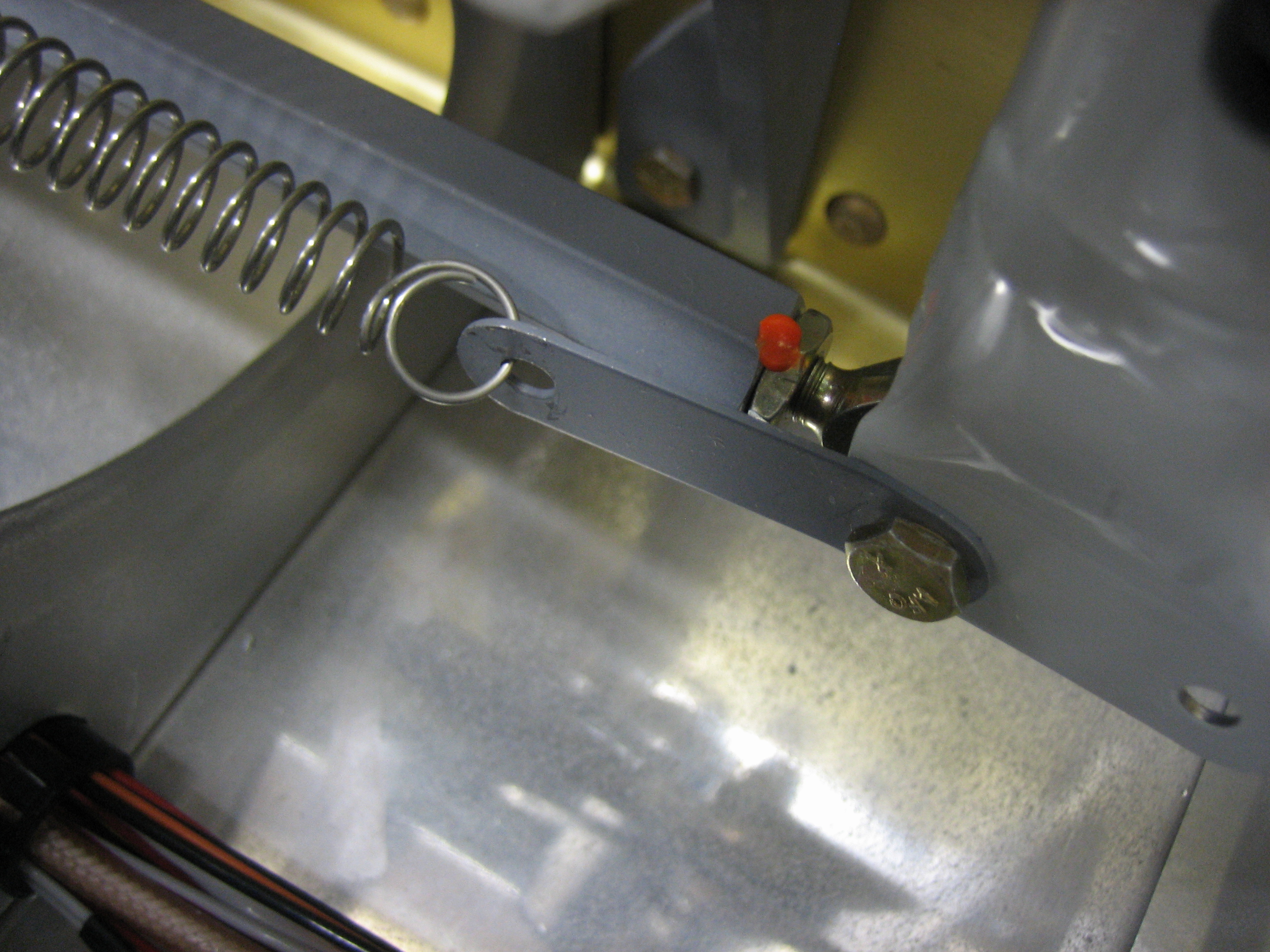
I then installed a washer between the stop and the vertical stabilizer rear spar on the left side.  This helps establish the cant in the vertical stabilizer.

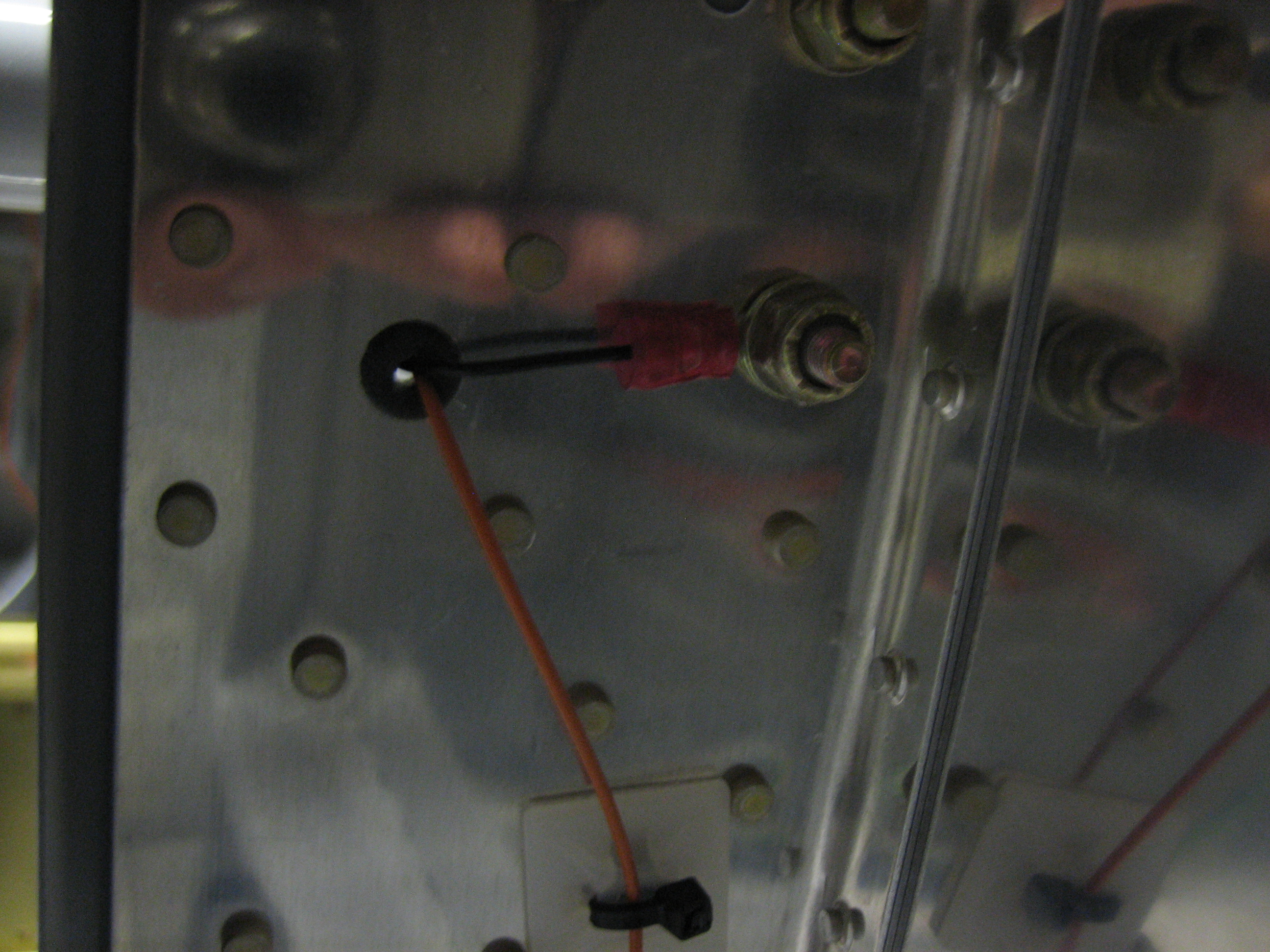
The ruler indicates the fuselage centerline.  You can see how the forward end is shifted left (we’re looking aft in this picture).  This counteracts the natural left turning tendency of the aircraft.

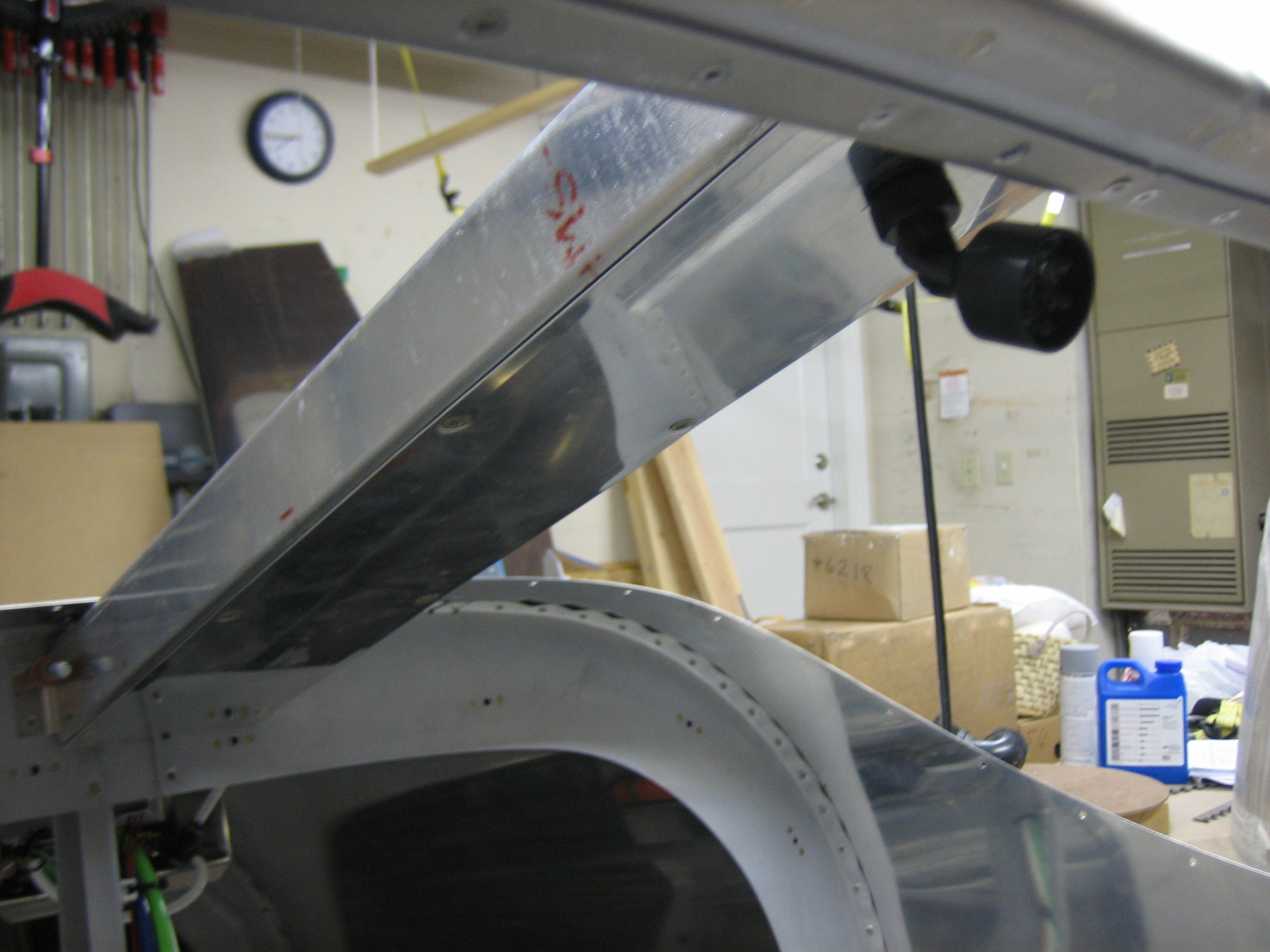
After triple checking all of the measurements, I drilled the splice plate to both the horizontal and vertical stabilizer front spars,

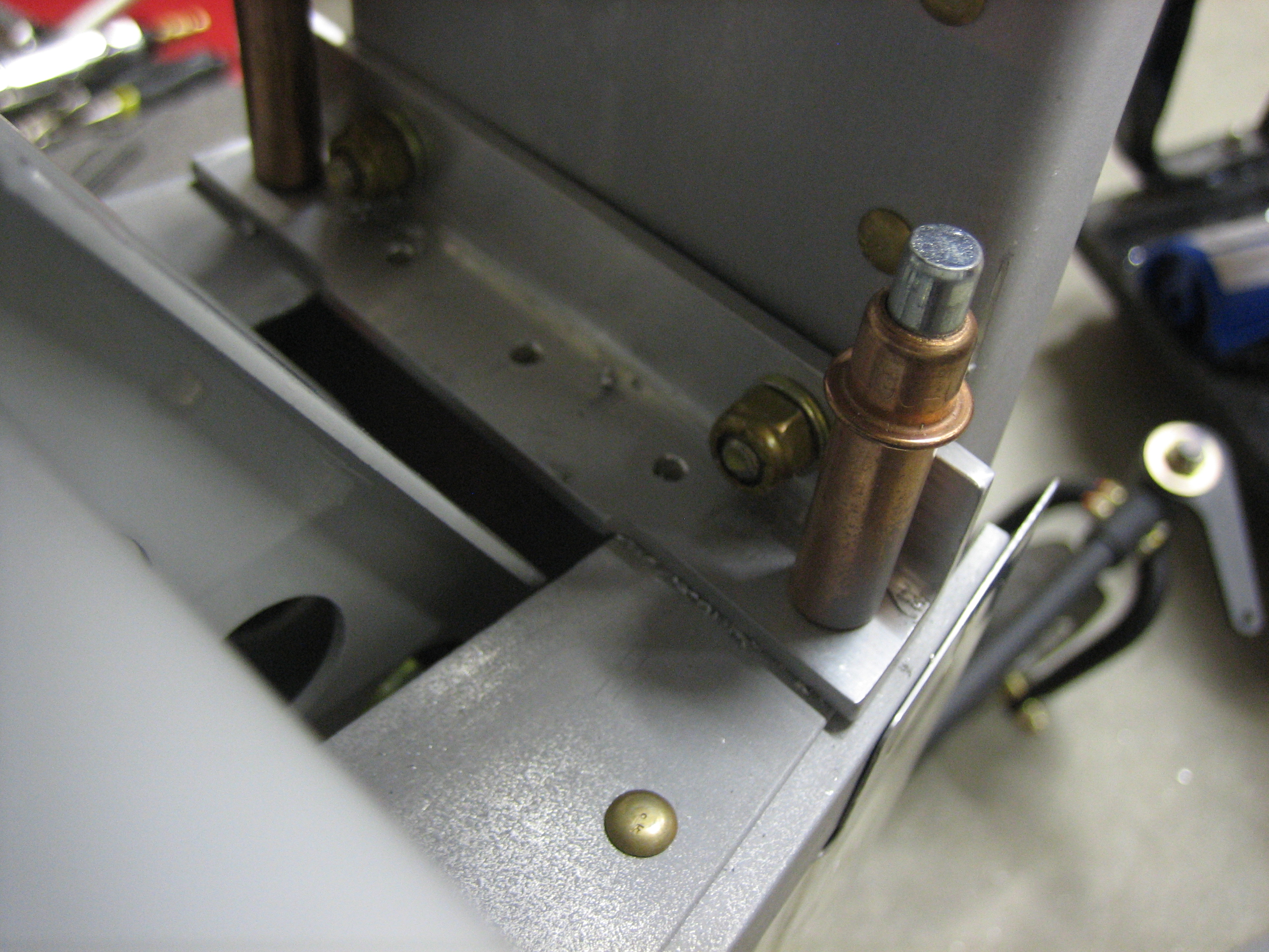
I then drilled the lower vertical stabilizer rear spar to the tailwheel attach bracket and then installed the rudder.  There is a little interference with the vertical stabilizer top fairing.  I’ll have to trim it back slightly.  It’s really late though, so I disassembled everything and put the plane back in the garage.


Finished Fuselage Wiring and Fabricated Flap Pushrods

I hooked up the canopy switch wires and verified the annunciator light illuminated appropriately.

I attached the ground wire to one of the canopy latch pivot block mounting bolts on the back side of the bulkhead.

I also installed a connector and some zip-tie bases in the roll bar support channel and hooked up the cabin light.

Finally, in preparation for mounting the wings this Friday, I fabricated the flap pushrods.  I cut the tubes from some 5/16″ stock with 0.058″ wall thickness and then drilled/tapped the ends for the 1/4″-28 bearings.

Mated the Wings

My brother Seth flew out from KY yesterday to help me mate the wings.  The weather was spotty in the morning, so we got started a little later that I’d have liked.  We pulled the plane out into the driveway and temporarily fit the wings with some hardware store 7/16″ bolts.

Next up, we leveled the fuselage laterally and hung two plumb bobs off of each wings.  I tied a piece of fishing line to the cord on the outer two plumb bobs so that I could easily compare the position of the inner two plumb bob cords to the line to see if the wings had any sweep in them.  I also took some measurements from the tail to make sure each wing had the same amount of sweep.  Finally, I checked the wing incidence on both sides to make sure they were the same.

With the wings straight, I installed the flaps to see how they fit against the fuselage.  The good news is that the height on both sides is perfect and the inboard end of the flap skins just kisses the bottom of the fuselage.  Unfortunately, with the wings perfectly straight, the joint between the flaps and the side of the fuselage wasn’t uniform.  The gap got progressively wider towards the trailing edge of the flap.  I decided to sweep the wings back slightly to make the gap uniform (I probably only brought the wing tips back 1/4″ or so from straight across).  This will make no discernible difference in the flying qualities, but the aesthetics of the flap/fuselage intersection are significantly improved.

After triple checking everything, I laid out some marks to ensure that I had 5/8″ of edge distance (from the center of the bolt) in all pieces, then progressively drilled out the hole to just under the final size.  I then used a 0.3115″ reamer to bring the hole up to final size providing a snug fit for the bolt.  I used a drill cup on the first three sizes to ensure that I was drilling absolutely perpendicular to the material.

My buddy Andre dropped by to check out the progress, and we drilled the bottom wing skin and the wing root fairings for #8 screws and my brother trimmed them to the fuselage.

Next, I installed the flaps and pushrods and cut out the flap pushrod holes.  These are odd shaped holes due to the changing geometry between the flap weldment and the flap as they’re moved up and down.

Heres a rough idea what the hole on the left side looks like.

The side of the fuselage has an arch shaped hole to clear the end of the flap pushrod when the flaps are fully retracted.

The bottom of the fuselage has a slanted and tapering hole to provide clearance for the pushrod and it moves through its range of motion.  I have about 1/8″ all around the pushrod in all positions.

Seth removed the tank attach brackets and bent them so that they’re flush against the side of the plane and flush with the back of the fuel tank attach bracket.  Afterward, I drilled the fuel tank attach bracket for the bolt that ties these together.  Once the wings are back off the plane, I install a nutplate on each bracket to allow these to be screwed together.

I was getting really damn cold.  I was still in shorts and a long sleeve t-shirt, and it had dropped to 46º before I gave up and decided to call it a night.  Hopefully I can rig the ailerons tomorrow morning pretty quickly.

More Misc Fuselage Tasks

My wife and I celebrated our 11 year wedding anniversary tonight.  She had to get up early for work tomorrow though, so I came out to the garage for a few minutes tonight to knock a few tasks off the to-do list.  I got started by crawling under the fuselage and deburring/scotchbriting the flap pushrod holes.

After that, I decided to torque and seal a bunch of the fuselage fasteners that are in for good.  First up, I retorqued the center pushrod jam nuts and sealed them.

Next, I torqued and sealed the bolts that secure the center pushrod to the control sticks.

Finally, I torqued and sealed the bolts that attach the tank attach brackets to the fuselage.

Rigged Elevators

I finished drilling the aft deck and longerons to the elevator up stop.

I also finished drilling/reaming the forward vertical stabilizer support bracket to the forward spar of the horizontal stabilizer.

The elevator down stop needed quite a bit of material removed to achieve the recommended amount of deflection.

With the up stop manufactured to plans, I get 31.1º of upward deflection (25º-30º is the specified range).  It looks like a number of builders have ended up with slightly more than the 30º limit.

With the adjusted down stop, I can reach 24º deflection from neutral (20º-25º is the specified range).  Since I plan on doing quite a bit of acro, I wanted to get near the upper limit.

Afterward, I adjusted all of the elevator pushrods to length and torqued the jam nuts.

I had to lengthen the servo pushrod from 6″ to 6 3/16″ center to center to put it at 90º to the servo arm when the elevators are neutral.  I also took the opportunity to prime the servo pushrod and torque everything down.  I still have the forward elevator pushrod to do and the final bellcrank connections to install/torque.

Finished Elevator Pushrods and Worked on Vertical Stabilizer

I finished up the forward elevator pushrod and installed it for good.  Putting the washers between the bellcrank arms and the bearing was a real pain in the ass and required using a washer wrench and looking in a mirror to see what I was doing.  I just noticed that I forgot to add torque seal to the jam nut on the rod end bearing.

I also installed the forward end of the aft elevator pushrod for good.  This didn’t need washers since it uses a larger bearing.

Installing the forward end of the forward elevator pushrod was also a real pain because the aileron interconnect pushrod really gets in the way.  This also needed washers between the forks of the arm, but at least I didn’t have to use a mirror to see what I was doing.

I finished drilling the vertical stabilizer forward spar to the attach bracket and deburred it.

I also epoxied a washer to the forward side of the vertical stabilizer rear spar on the left side since the vertical stabilizer is twisted to the left slightly to counteract the left turning tendency of the airplane.  I also countersunk and installed an AN426 washer in the center hole here since I had to drill out the AN470 rivet I installed there.

When I drilled the bottom of the vertical stabilizer to the tailwheel mount bracket and aft bulkhead, it left some tiny metal shavings between the two pieces.  Fortunately, I had this chip chaser which did a great job of cleaning these out so that the two pieces lay flat against each other.

This is not an airplane part, but the attach point on my inspection mirror finally broke.  I mixed up some epoxy and flox and glued it back together.  This is probably far stronger now than it was originally.

Installed Aileron Pushrod Boots and Gemini Pitot Tubing

One of the biggest sources of air infiltration in the RV is the large hole in the side of the fuselage that allows the aileron pushrod to exit the fuselage.  When flying at high altitudes, ice cold air comes in through this hole and then comes up through the seat belt attach holes, stick boot hole, etc.  It also makes the seat pans really cold which can make sitting in the plane really uncomfortable.  The solution to this is to install boots around the pushrods to block the air.

I installed the aileron pushrod boots from Classic Aero Design.  These are more expensive than others on the market, but after installing them, I think the extra cost is absolutely worth it.  These are very well designed and really easy to install.  First up is to install the mounting ring.  This is flexed into place so that the foam covered flange tucks between the outer fuselage skin and the adjacent rib.  The ring is then expanded outward until the predrilled holes align.  A couple of pop rivets anchors the rings in place.

Next, a strip of adhesive backed foam is adhered to the outside of the flange.  Notice that the inboard edge of the flange is bent outward slightly.

The boot is then installed over the flange and a zip-tie is used to cinch it down against the foam strip.  The bent edge of the flange keeps the end from popping off the flange.  Once the pushrod is installed for good, another foam strip will be adhered to the pushrod and the inner zip-tie will be used to anchor it.

Finally, I tapped into the pitot tube to run a line up to the Gemini.  I spoke with TruTrak yesterday, and the Gemini PFD has been delayed a couple of months, so they’re going to send me the Gemini ADI which has the exact same mounting holes and wiring/plumbing connections.  Once the PFD is available, I’ll swap the ADI out for it.

Installed Heater Control Cable

I installed the heater control box cable tonight.  The control is mounted on the far right of the instrument panel which provides for a fairly easy routing.  The cable curves down over the rudder bars and is attached to one of the firewall support angles with an adel MS21919-WDG3 adel clamp and then passes through a 1/4″ hole in the vertical firewall support angle behind the wire bundle.

The housing will be anchored with another adel clamp to the bolt on the right and the protruding wire will attach to the b-nut on the flapper arm.  There’s no point hooking these up now since the control cable has to be removed when the instrument panel comes out for paint and labeling.

More Work on Oil Cooler Plenum

I trimmed the edges of the large aluminum area washers that surround the vent tube ports on the side of the fuselage.  I then primed and installed them

Finally, I covered the oil cooler plenum and butterfly valve with packing tape so that I can layup some fiberglass over it.  Because of the compound curves of the mold, I had to use a number of narrow strips to avoid wrinkles.