Installed Manifold Pressure Restrictor and Aileron Trim Cable

One of my old college buddies Matt was in town this weekend to visit.  I was hoping we’d have more time to work on the plane, but at least we had a little.

I received this brass restrictor fitting from Wick’s Aircraft today.  It has a 0.040 hole drilled in the middle to dampen out the pressure changes so that the manifold pressure sensor reading doesn’t fluctuate wildly.  Wick’s has a $15 minimum order, so I had to pay an extra $5 fee since this is all I ordered.  I was going to add a couple of other parts onto the order that I need so that I didn’t need to pay the fee, but their prices are substantially higher.  Companies with minimum order sizes piss me off anyway, so this will be the last time ordering from Wick’s if I can help it.

I also got an order from Aircraft Spruce with some more Ray Allen servo cable for the aileron trim.  Matt helped install the connectors on the ends and I wired it to the VP-X alongside the pitch trim cable.

Under the seats, I installed a 5 position molex connector to attach the cable to the aileron trim servo.

Sealed Firewall Recess and Started Modifying Axle Nuts

I used some 3M FireBarrier 2000+ to seal the openings around the firewall recess so that I can finish off attaching things to the firewall.

While waiting for that to dry, I started modifying the axle nuts for the Avery Tools jack stand brackets.  I drilled the nutplate out from the end of the nuts and then drilled a 1″ hole in the end of each nut using a 1″ hole saw.

The bracket will get installed over the end of the nut and the nutplate will be reinstalled on the bracket.  A groove will need to be filed in each nut so that this bracket will be flush with the end, but this will wait until I’ve drilled the axles to the nuts so that I can install these brackets parallel with the ground.  This will make it easier to reach the screws on each side so that I can take the bracket off when jacking up the axle.

Installed Throttle Cable Bracket

For some reason, I decided to install the throttle cable bracket tonight.  I fabricated this bracket months ago, but it needed to be powder coated before it could be installed.  I sprayed a couple of coats of white powder coat on it and baked it for awhile in my toaster oven.

I then drilled the heads of a couple of coarse thread AN4 bolts and installed the bracket to the boss on the front right of the engine.  It was a little tight getting the safety wire installed, but I managed to get it done on the first try.

I’m not sure why I took this picture, but here’s a shot of the other side.

Tidied Up Firewall Forward Wiring

I got an order from McMaster Carr that included some more silicone adel clamps along with some tefzel zip-ties.  I installed a few to secure all of the wires near the right firewall pass-through.

This nicely tidied up the EGT, CHT, and Lightspeed Ignition wires running across the upper engine mount tube.

I also replaced a bunch of the temporary nylon zip-ties with the tefzel.  Regular nylon zip-ties are only good up to about 185º F.  Black, UV stabilized zip-ties are better at up to 221º F, but tefzel is good up to 300º F.  There are even higher rated zip-ties such as PEEK which is good to 500º F, but they’re over $3 per zip-tie!  All of the wire insulation in the plane is also tefzel insulated, so if it’s hot enough that these zip-ties melt, I’ll have other problems.

I also finished up the Dynon GPS mounting bracket.  I put a gentle radius in the lower flange to follow the curve of the engine mount and drilled a few lightening holes.  I then primed and painted it gloss white.

Installed GPS Mount and Started Instrument Panel

With the mounting bracket painted, I installed it on the engine mount.

The EGT and CHT wires from cylinders 1 and 3 run under the bracket and pick up the GPS wires.

There is still plenty of access to the back of the engine for oil changes and maintenance.  I like this approach so much better than the shelf that many builders go with.

I then finished up securing the wires along the top left engine mount tube.  This bundle picks up the oil temperature sensor, manifold pressure sensor, oil pressure sensor and fuel pressure sensor wires along the way.

I’ve been working on my panel layout on and off for many months.  I’m happy with it now, so I started transferring it to the panel this afternoon.  You can’t see much here, but my computer model was perfect.  Everything fits exactly as it should with the clearances I determined in the computer.

Here’s a rendering of the panel from the modeling software.  The only thing not pictured here is the hobbs meter.

Resumed Work on Baffles

With the cowling fit, I resumed work on the baffles.  After a little trimming where the baffles fit around the rocker arm covers, I got everything mounted to the engine except for the part behind the spinner.

I had previously cut off the flange from the aft baffle support since it pushed the aft baffle walls too far back.  I fabricated I replacement from some 1/16″ angle stock and riveted it to the baffle support.

To ensure the aft wall is in the right spot, I clamped a straightedge across it.  I then clamped the bracket to the wall and drilled the holes.

With the aft baffle wall bolted to the support, the back wall becomes very rigid.

I made the preliminary angled cuts on the ramps and made the necessary bends in the forward side baffles.

With a little trimming back of the side baffles, I got the cowl to fit down behind the spinner.  You can see that it’s still nearly 1″ too high, so I’m going to have to cut off quite a bit of material to get the cowl to drop all the way down and then further to have the necessary clearance between the cowl and the baffles.  The engine can move around quite a bit due to the flex of the engine mounts, and you don’t want the baffles to contact the cowl.

The standard way to trim the baffles is to line the top with paper clips and then put the cowl on top.  The cowl will push some paper clips down more than others. You can then measure down some amount from the top of each paper clip to create a cut line that perfectly follows the curvature of the inside of the cowl.

Trimming Baffles

No pictures tonight, but I went through a few iterations trimming the baffles.  The cowl is quite a bit lower, but still not all the way down.  I probably have at least 1/2″ to go if not more.

I also started trimming the ramps.  I have no idea why they give you so much extra material; you have to cut quite a bit of it off before you can even start bringing the lower cowl up into place.

Ramp Crossing Bends and Instrument Panel Prep

I trimmed the forward ends of the ramps to within 1/2″ of the final dimension and them marked them for the crossing bends.  These bends allow the ramps to follow the slope of the cowl inlet.  The ramp on the left side is pretty deep since the air filter will be installed here.

The ramp on the right side is quite a bit shorter since the #1 cylinder is farther forward.

From the back side, you can see that the ramp follows the slope of the cowl inlet.  The ramp will get trimmed to be exactly flush with the inlet and a piece of baffle seal material will bridge the gap to prevent air from leaking.

I also trimmed off 1/2″ from the top of the Experimental Air throttle bracket so that I can have a little more knee room.

I’m going to have this TIG welded to the bottom of the instrument panel, flush with the front of the panel.  I’ll grind the weld flat so that this will be a seamless transition once painted.

Installed Control Cables

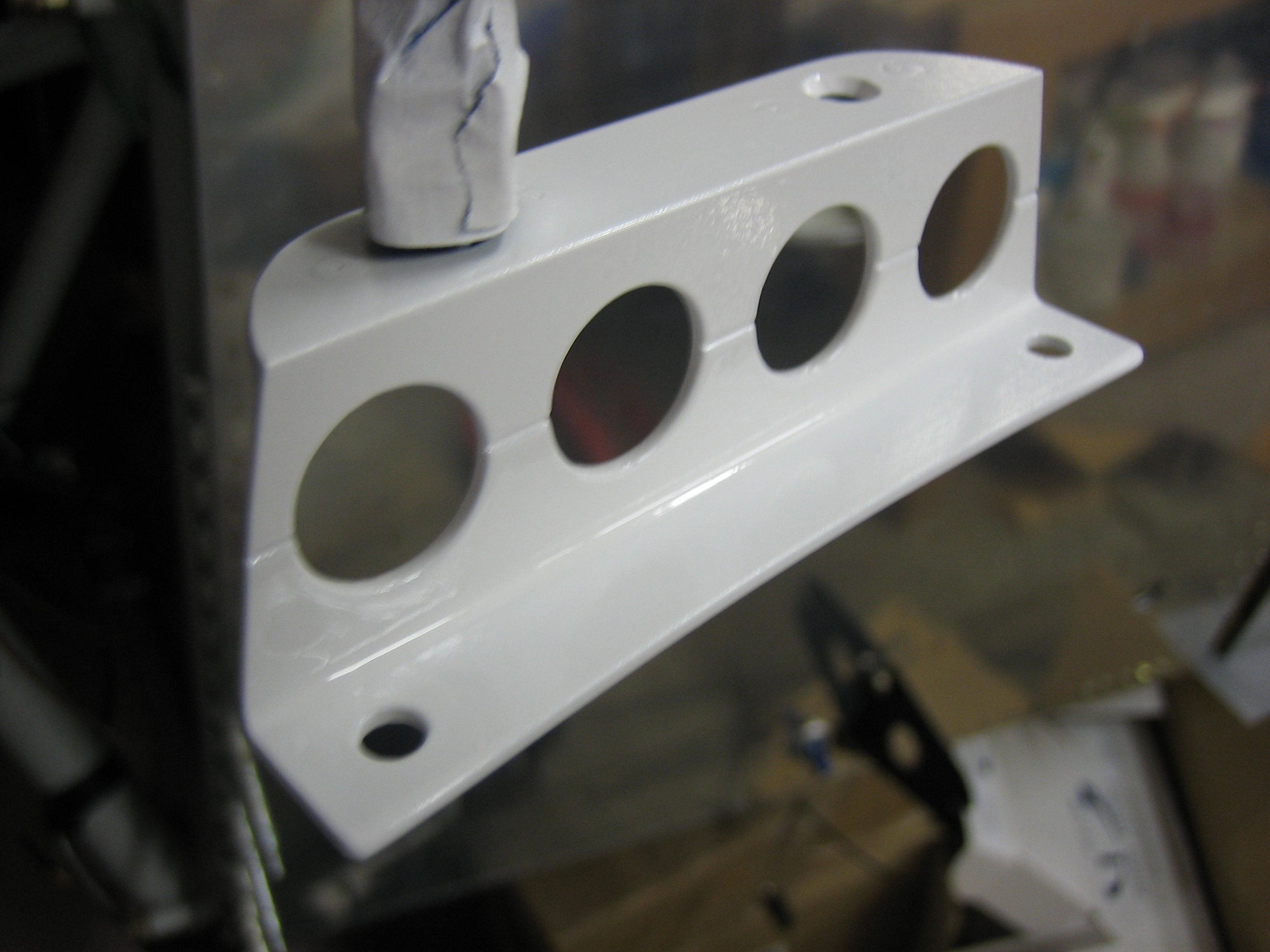
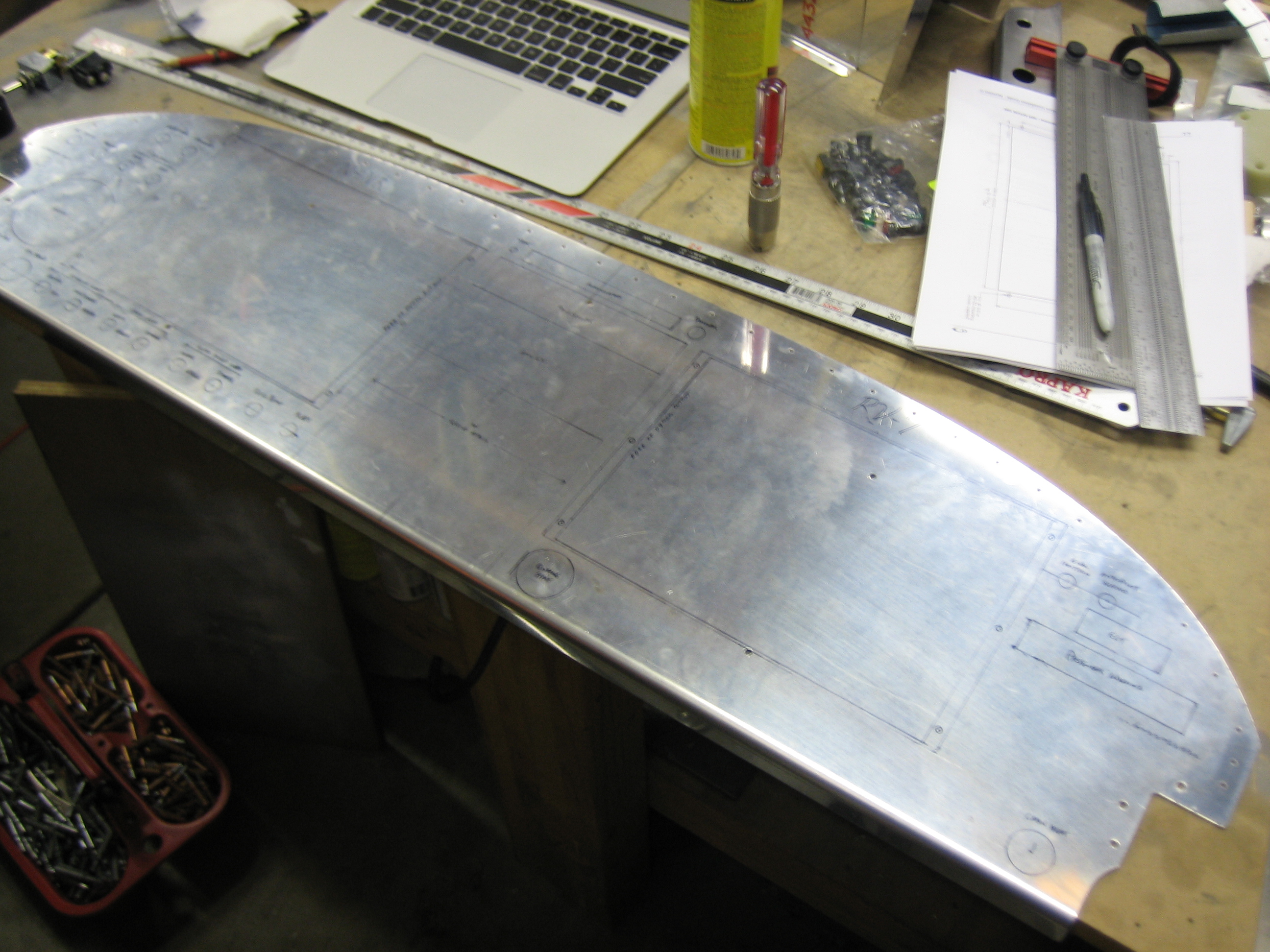
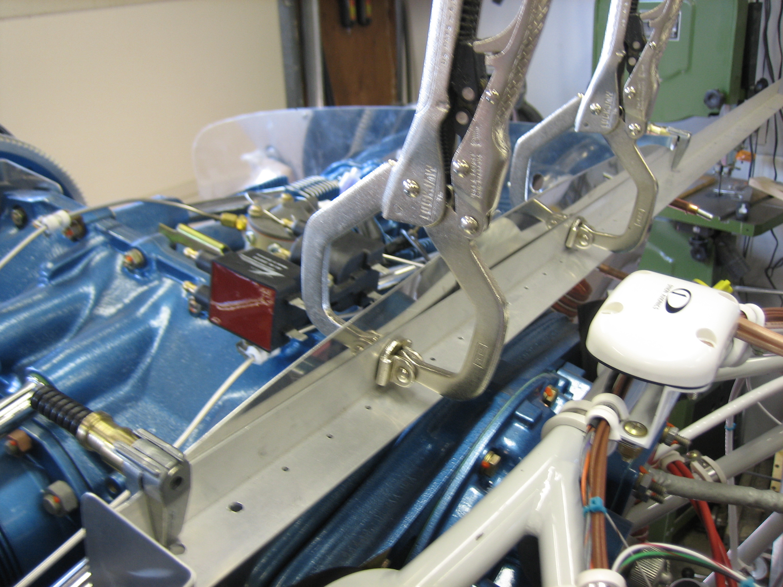
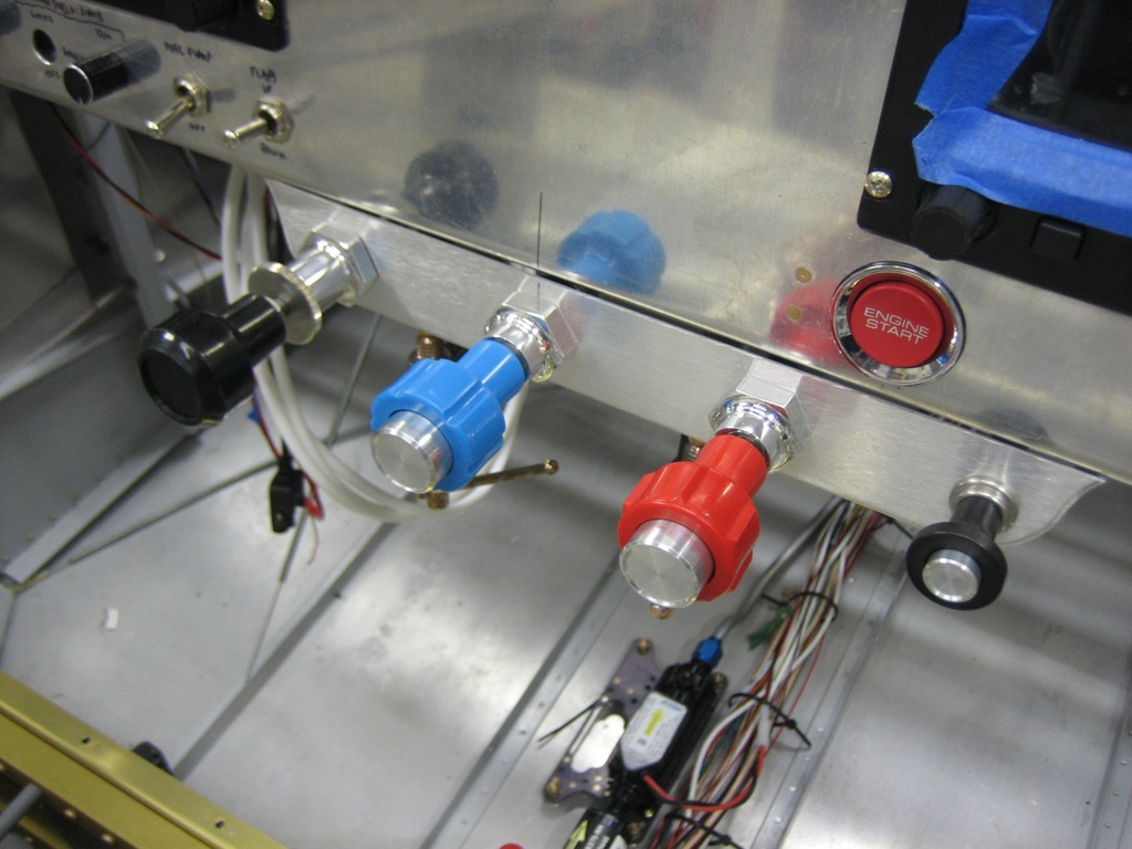
I installed the control cables in the bracket and clamped it to the panel with a couple of c-clamps.  You can see that I offset the bracket to the right so that the three engine controls are centered on the panel.  I did this to give myself more knee room.  It will be very rare that I fly with someone as tall as me (6′ 4″), and no one will ever take off or land from the right seat, so their knee room isn’t as important.  The small knob on the right is the parking brake.

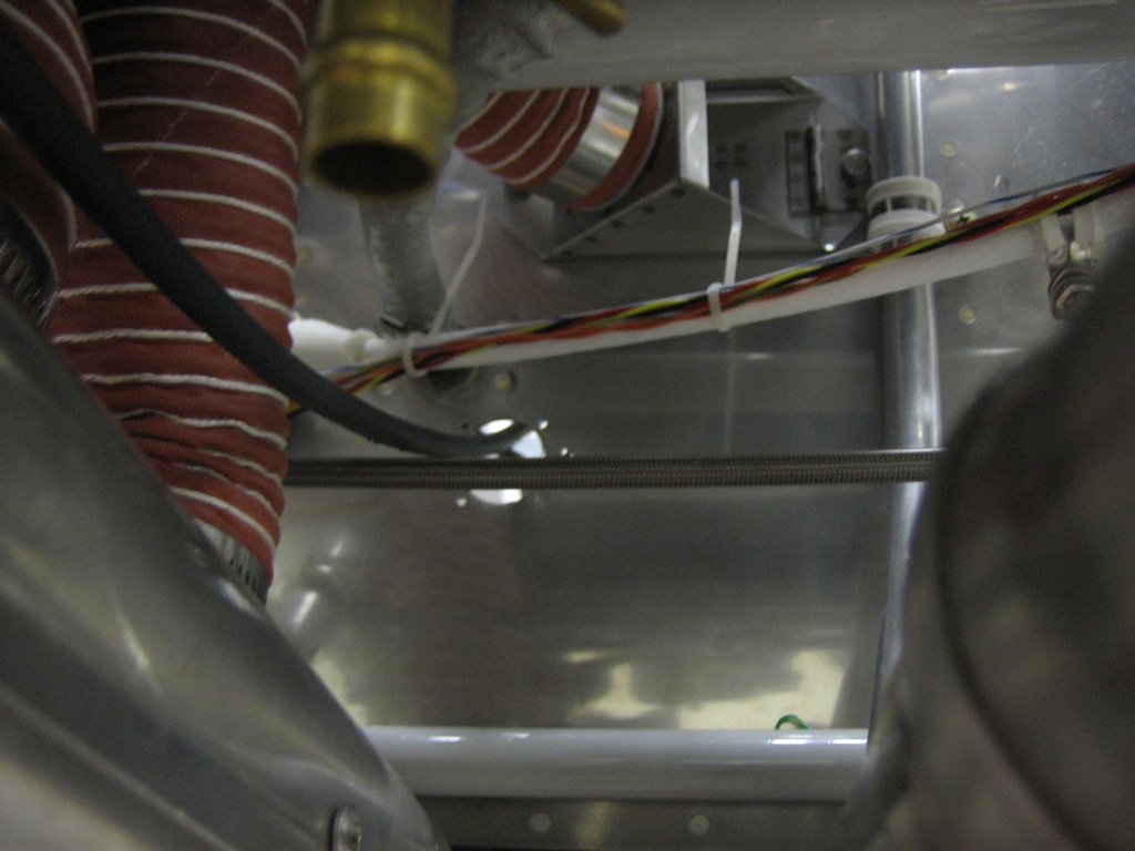
The throttle cable comes through the hole below the cabin heat box.  I haven’t installed the eyeballs in the firewall yet since I’m just trying to make sure the cable lengths are correct and determine where they will run.

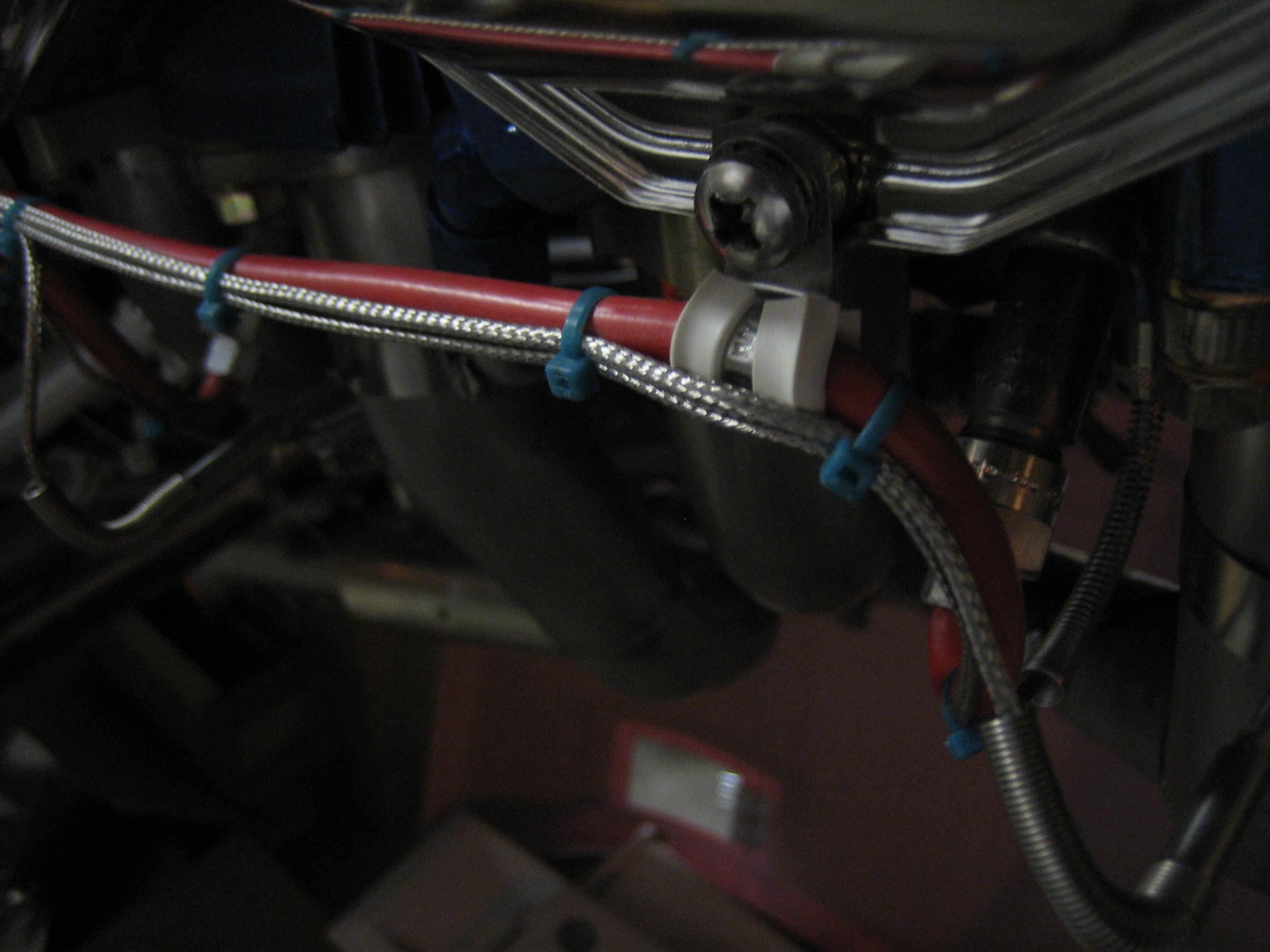
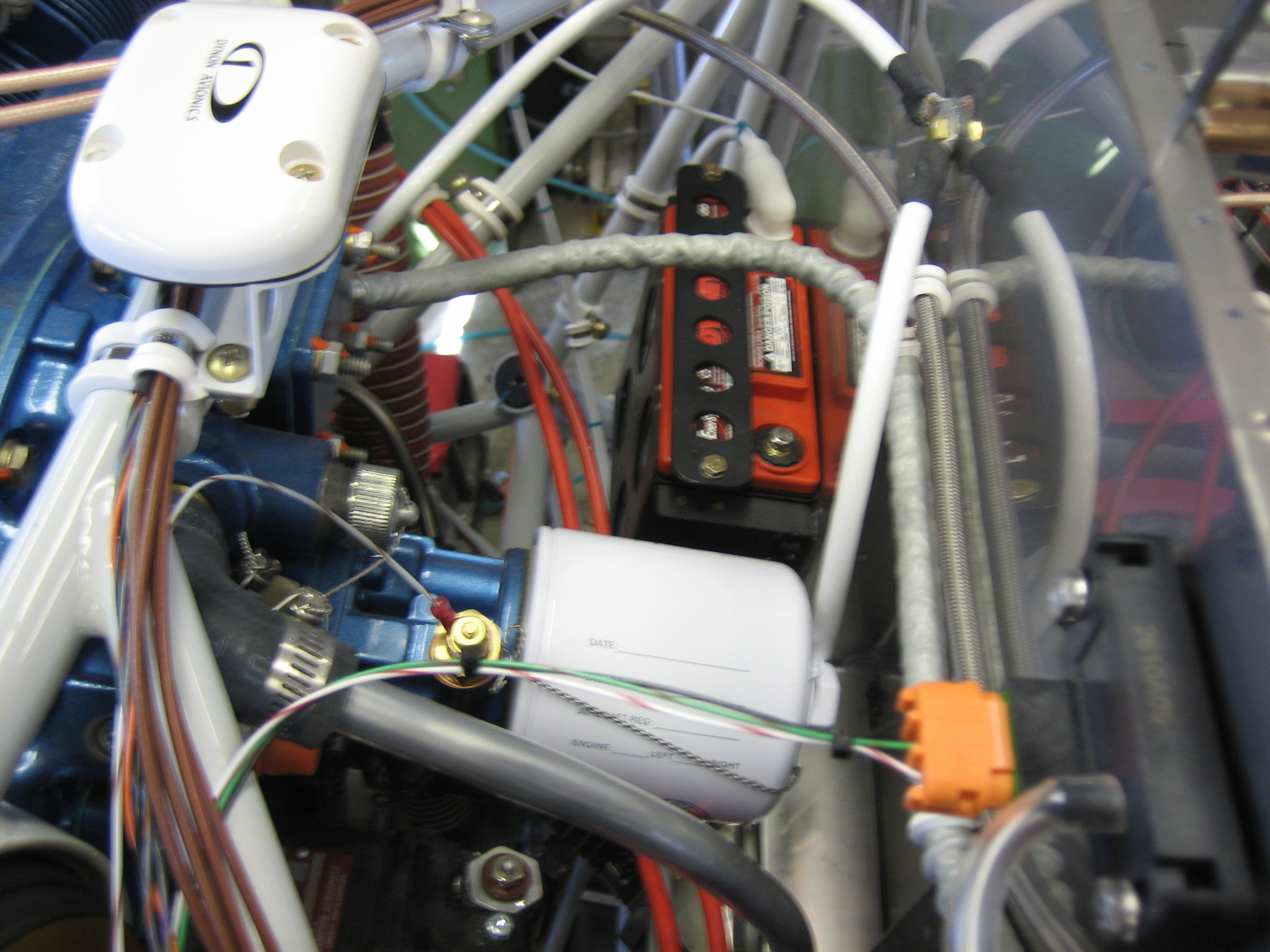
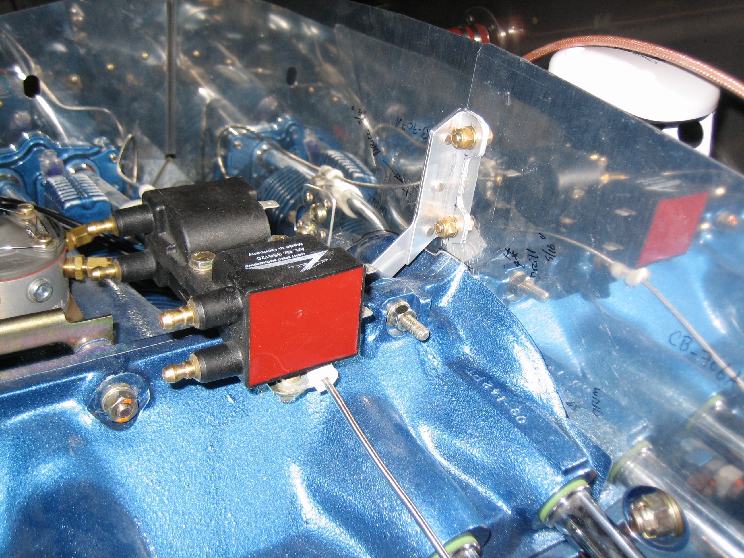
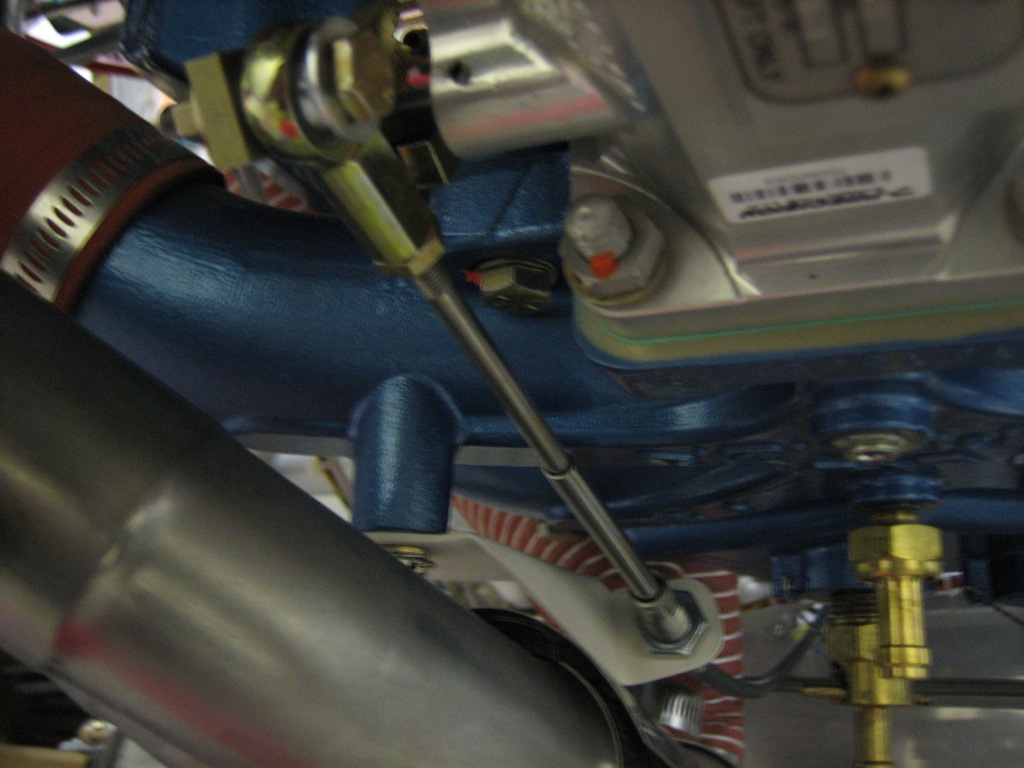
The throttle cable attaches to the custom bracket I made and then to the throttle arm.  The length and fit of the parts is perfect.  I can easily adjust the throw so that the knob is sticking out about 1/8″ when the throttle bracket hits the stop (you do this so that you know you’re hitting the control arm stop and not just the cable stop).  I’m going to replace this all-metal stop nut (which is acceptable) with a drilled bolt, castle nut and cotter pin (which is preferred).

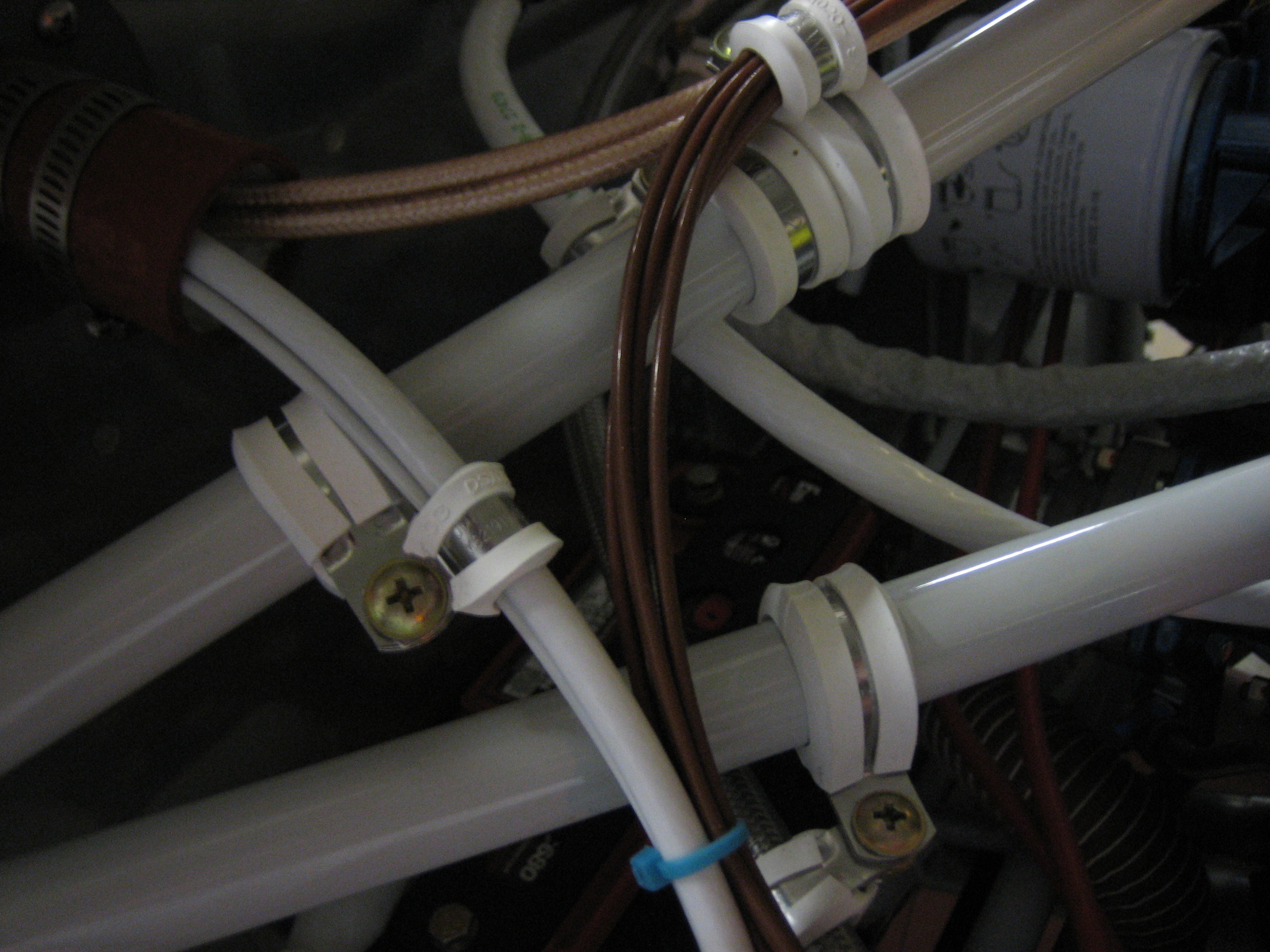
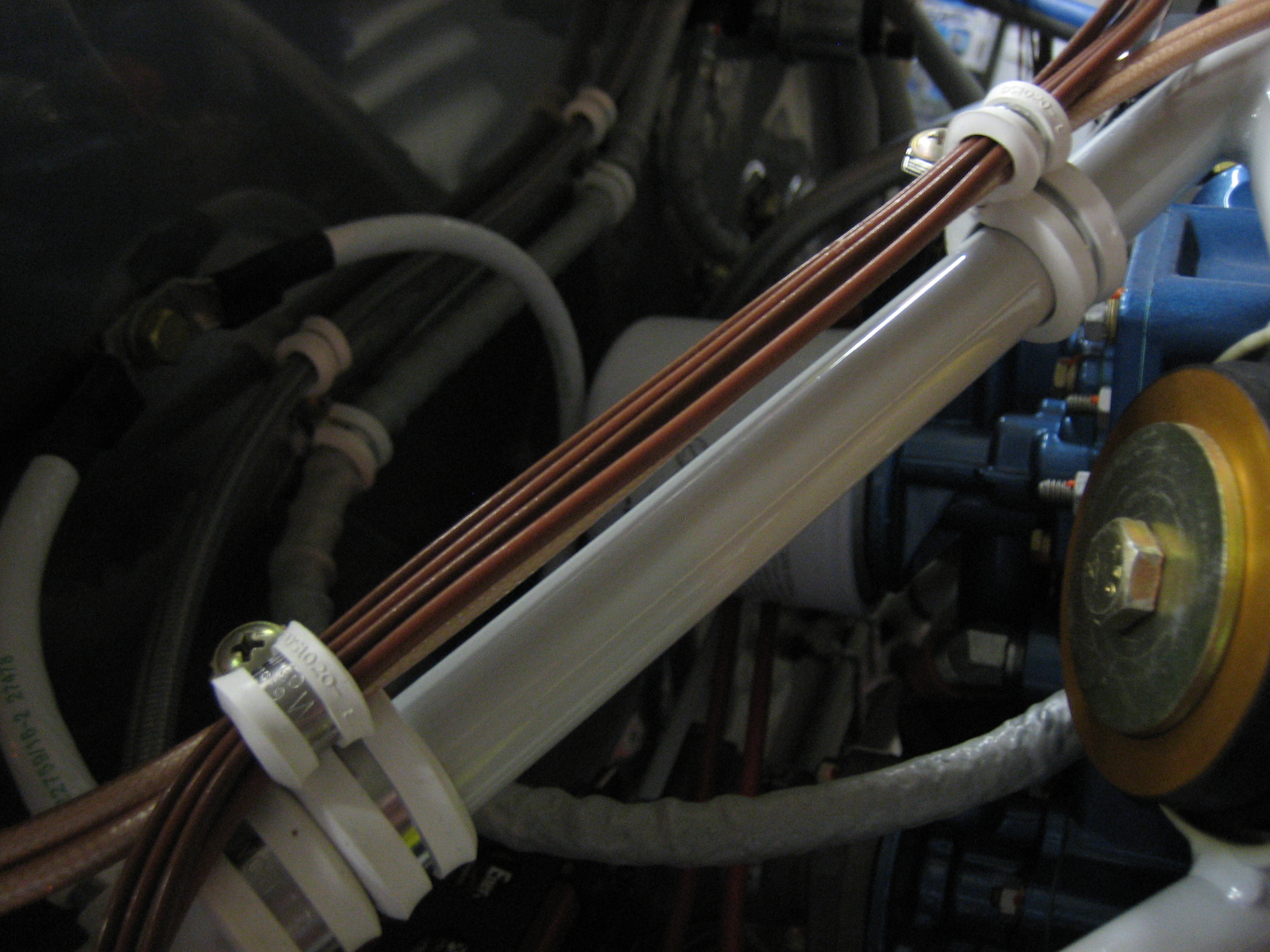
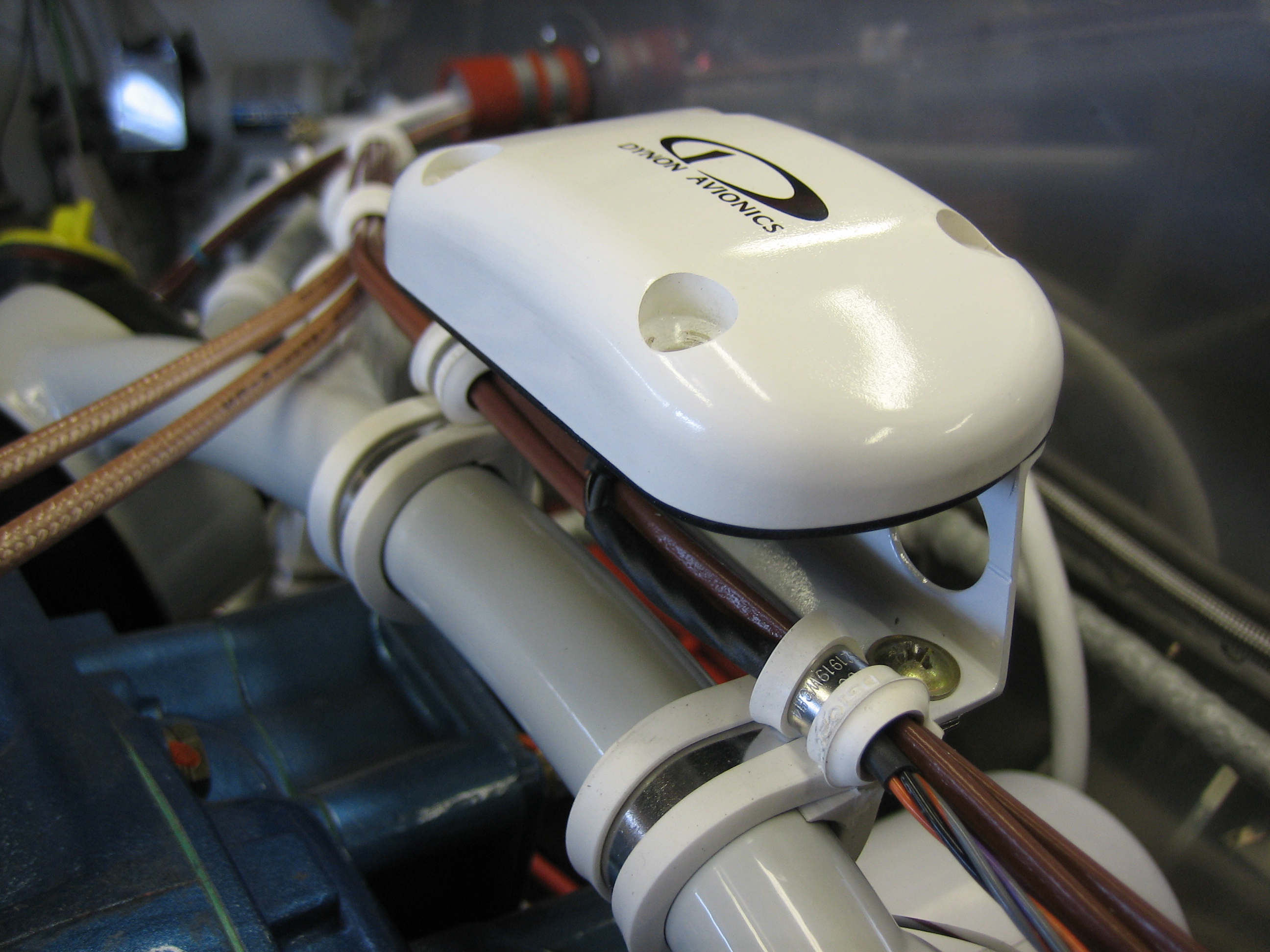
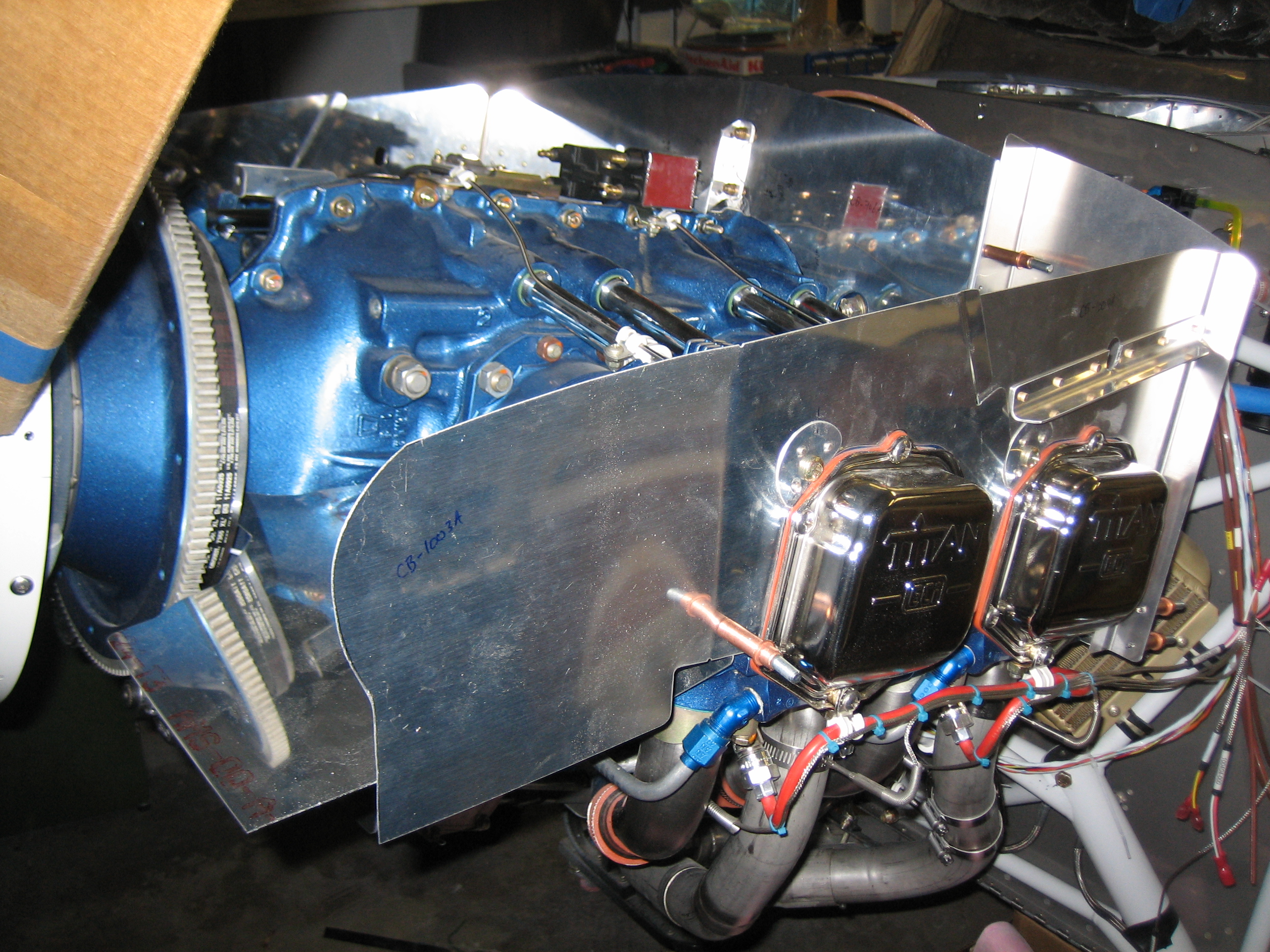
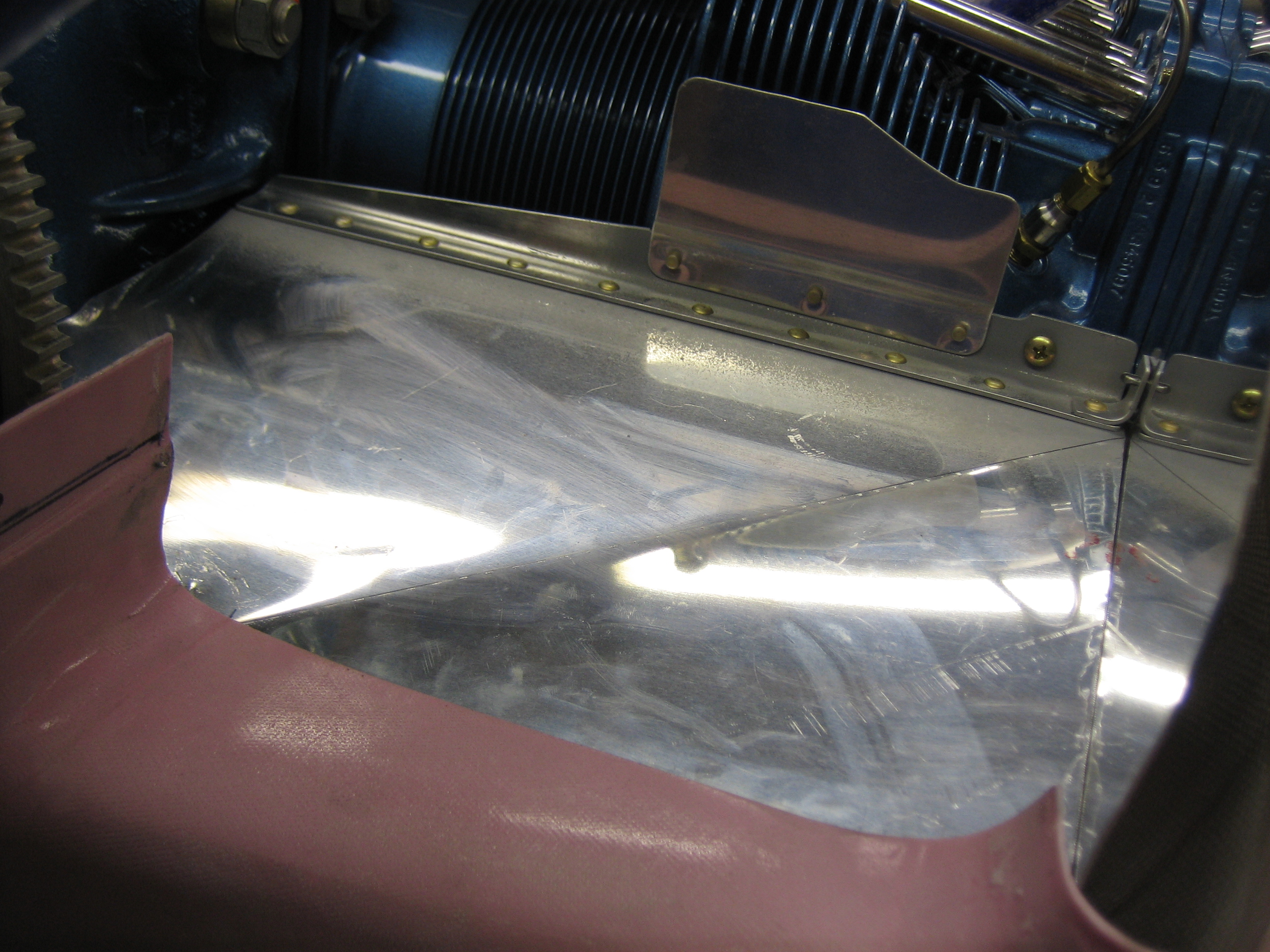
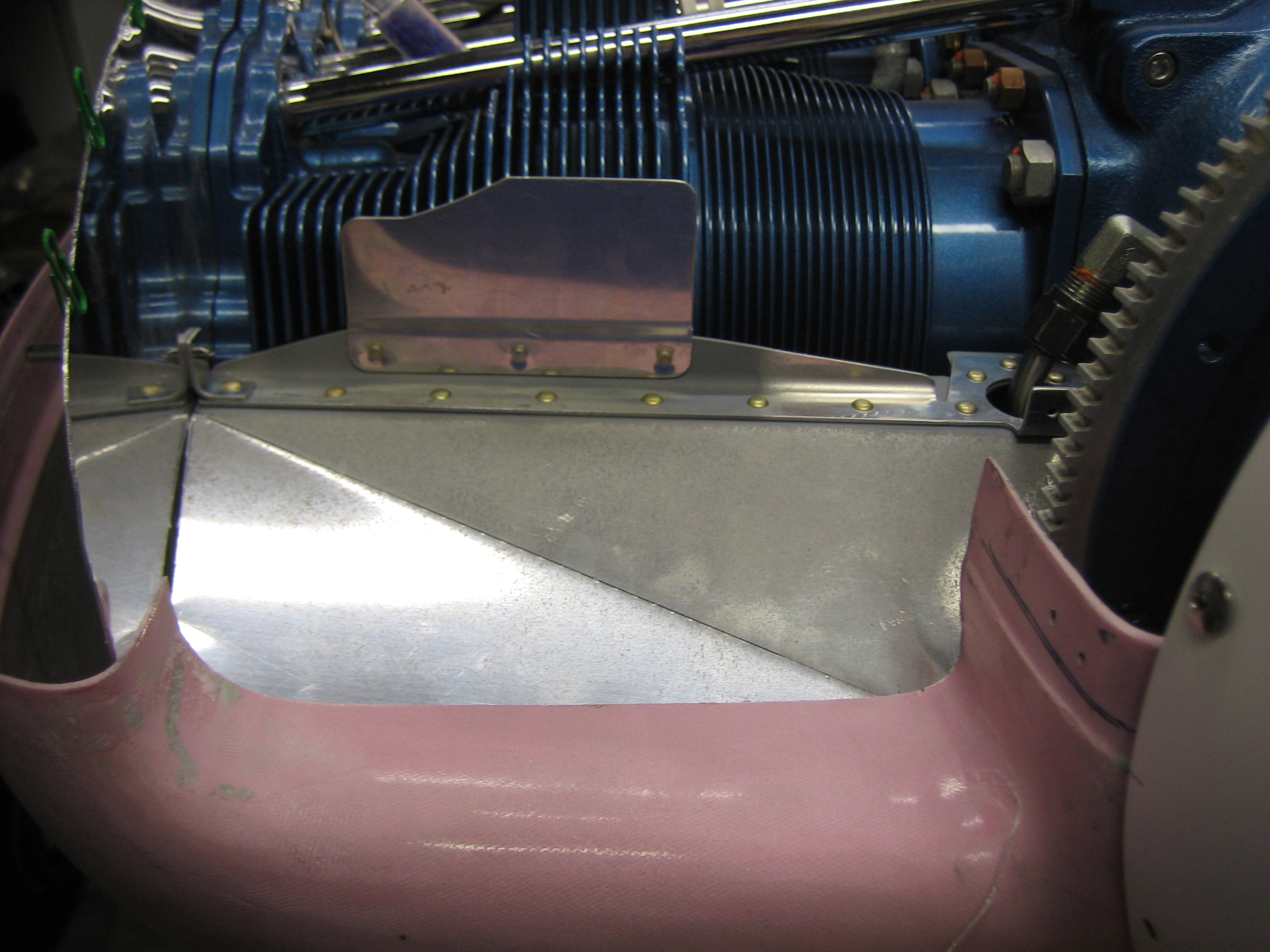
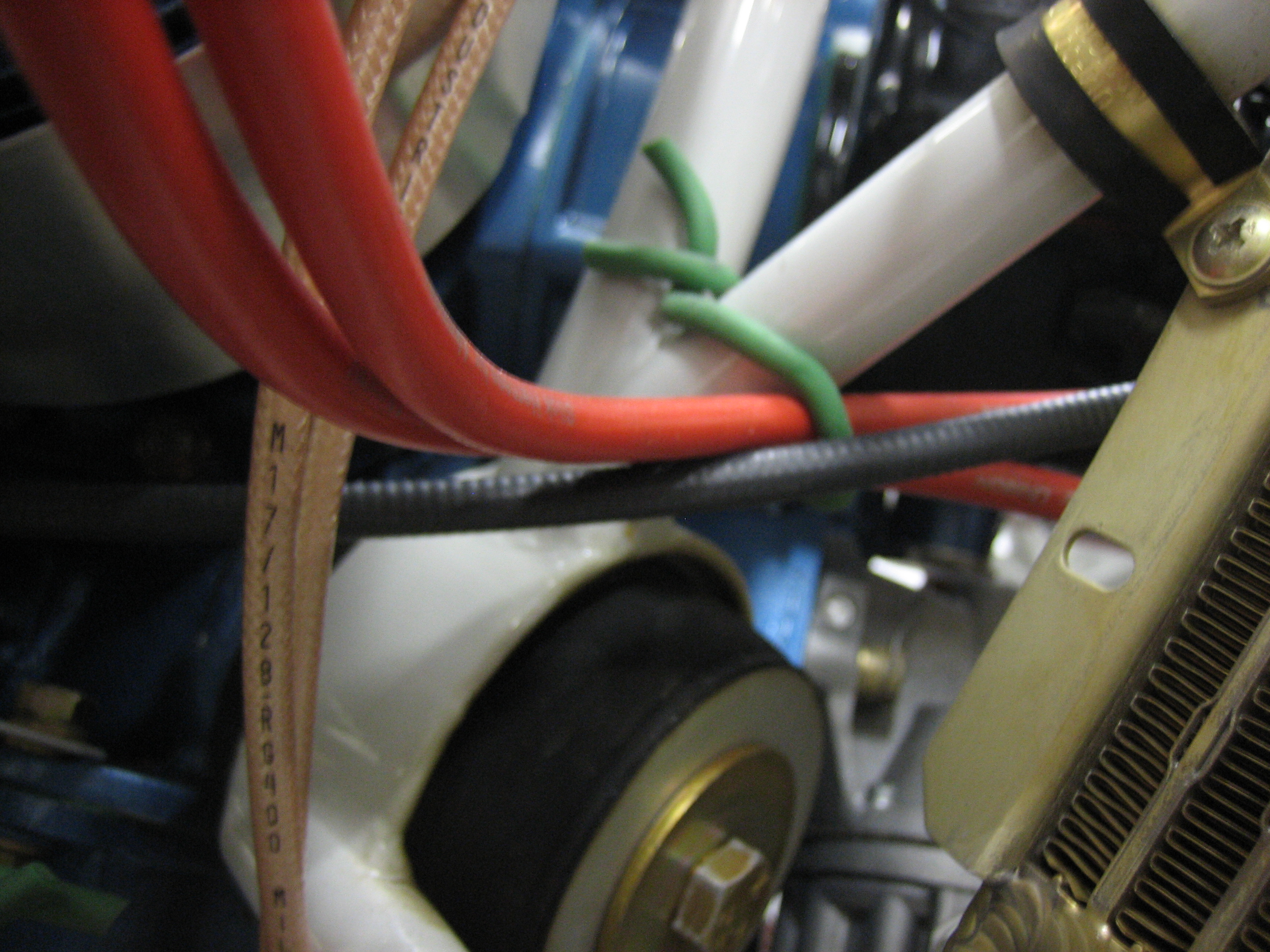
The mixture cable penetrates the hole just under the manifold and runs just above where the oil cooler will be mounted.  I’ll use some adel clamps to keep everything from rubbing on the oil cooler flange.

The cable then drops below the engine mount tube holding the oil cooler and on up to the mounting bracket.

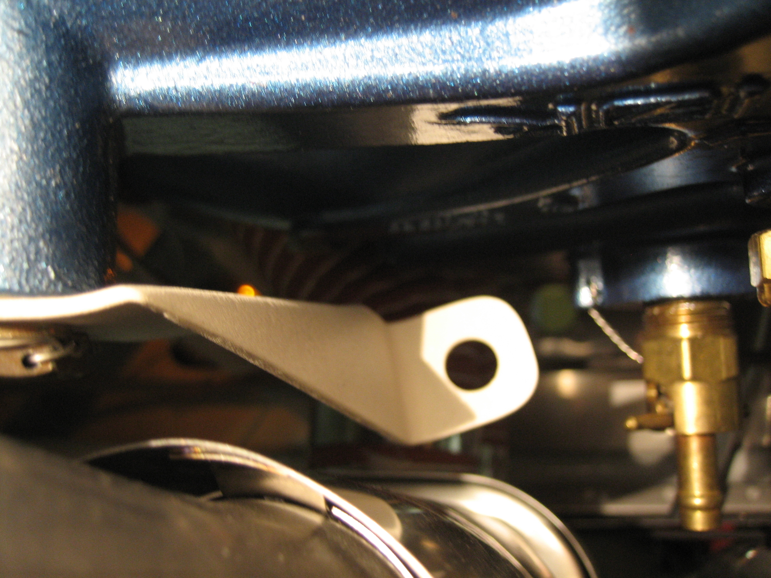
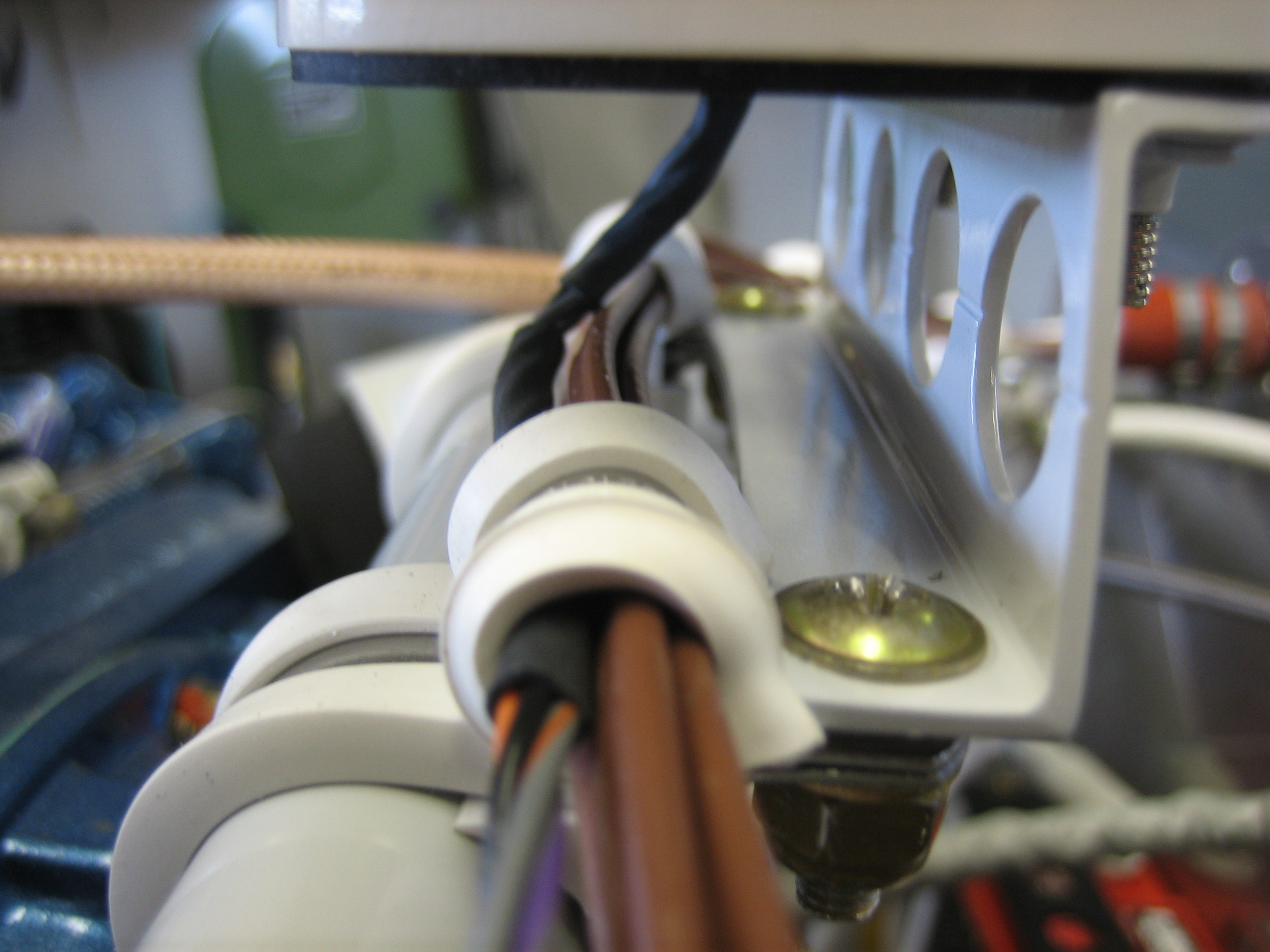
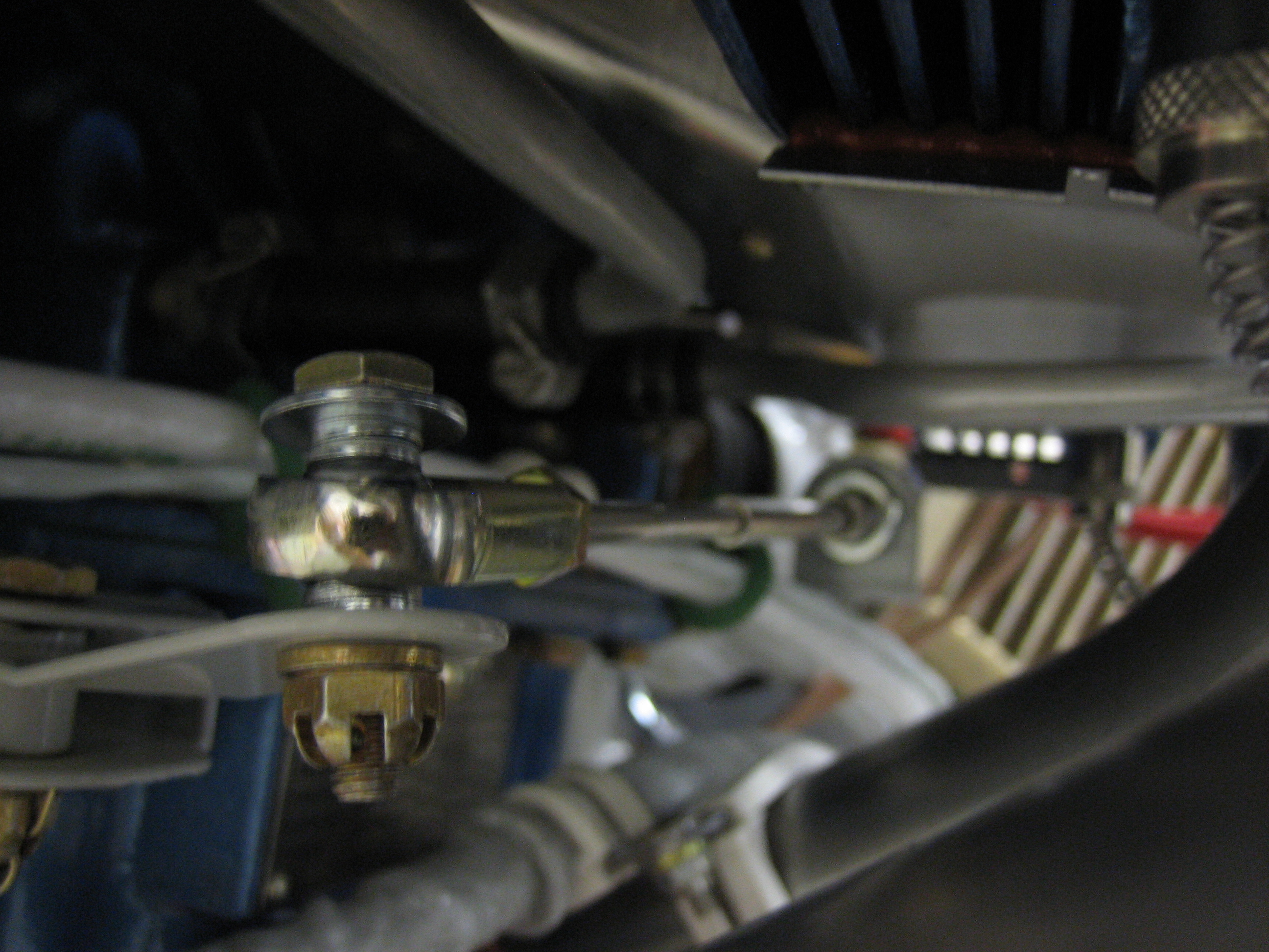
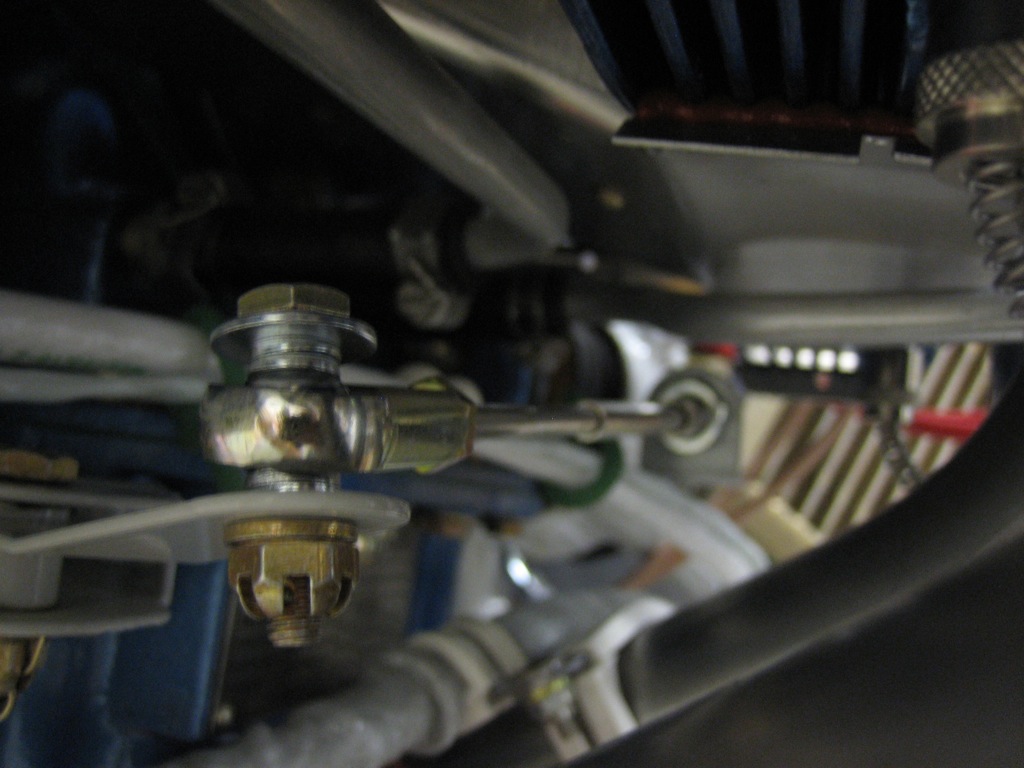
The forward end of the cable connects to the mixture idler arm.  I had to lengthen the small pushrod at the other end of the idler arm to get the mixture control arm to contact the stop, but in the end, it works beautifully.

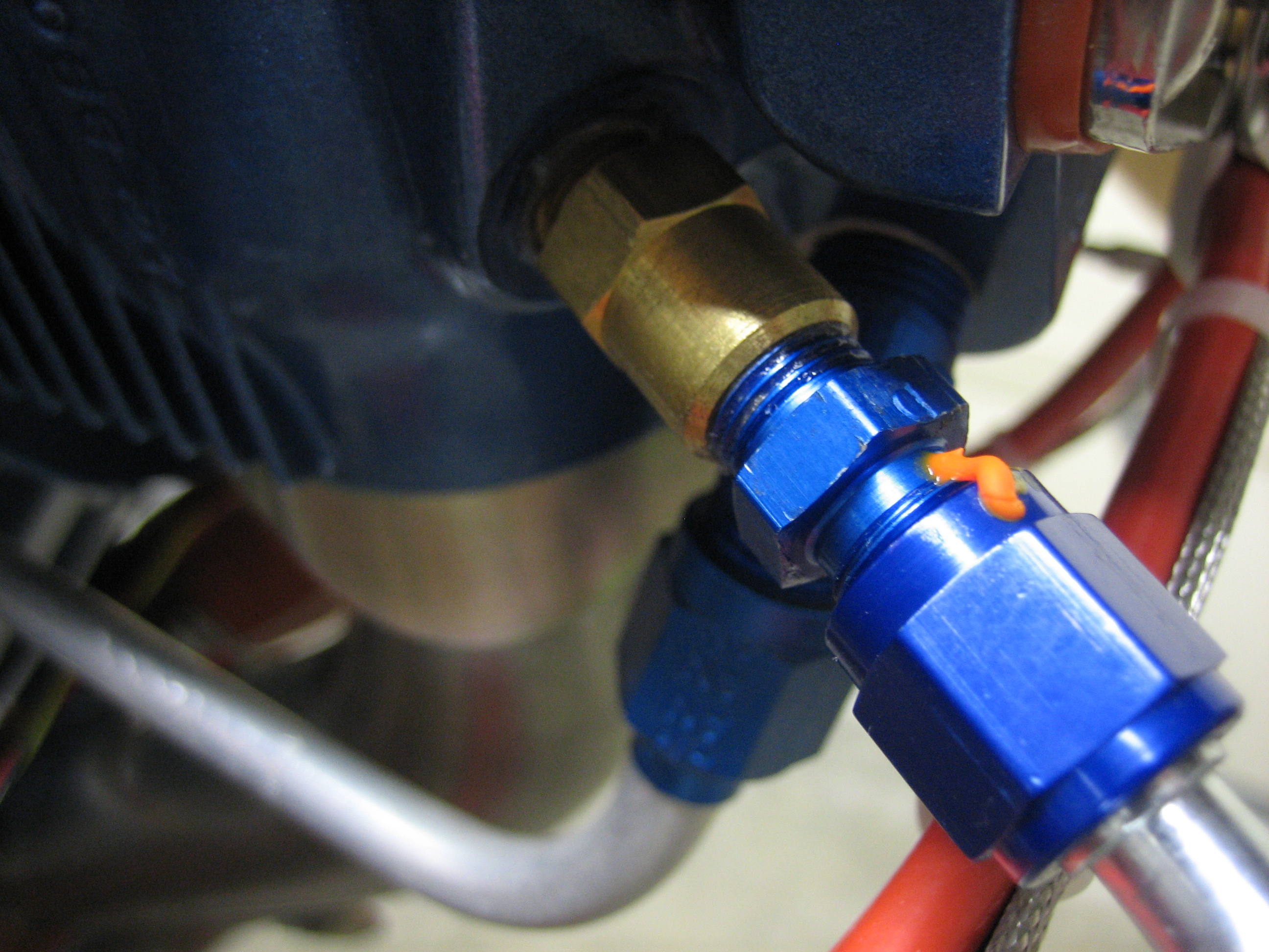
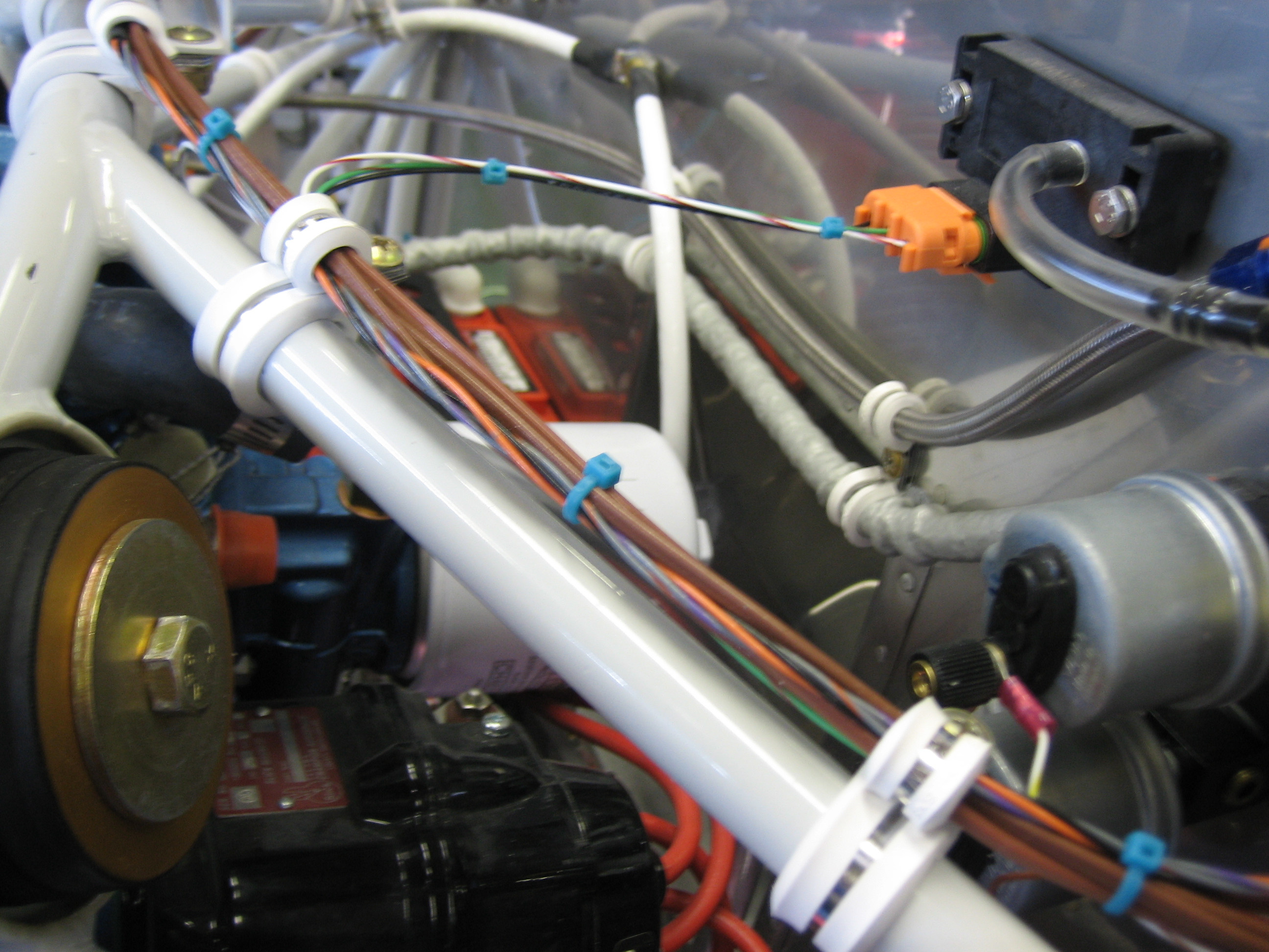
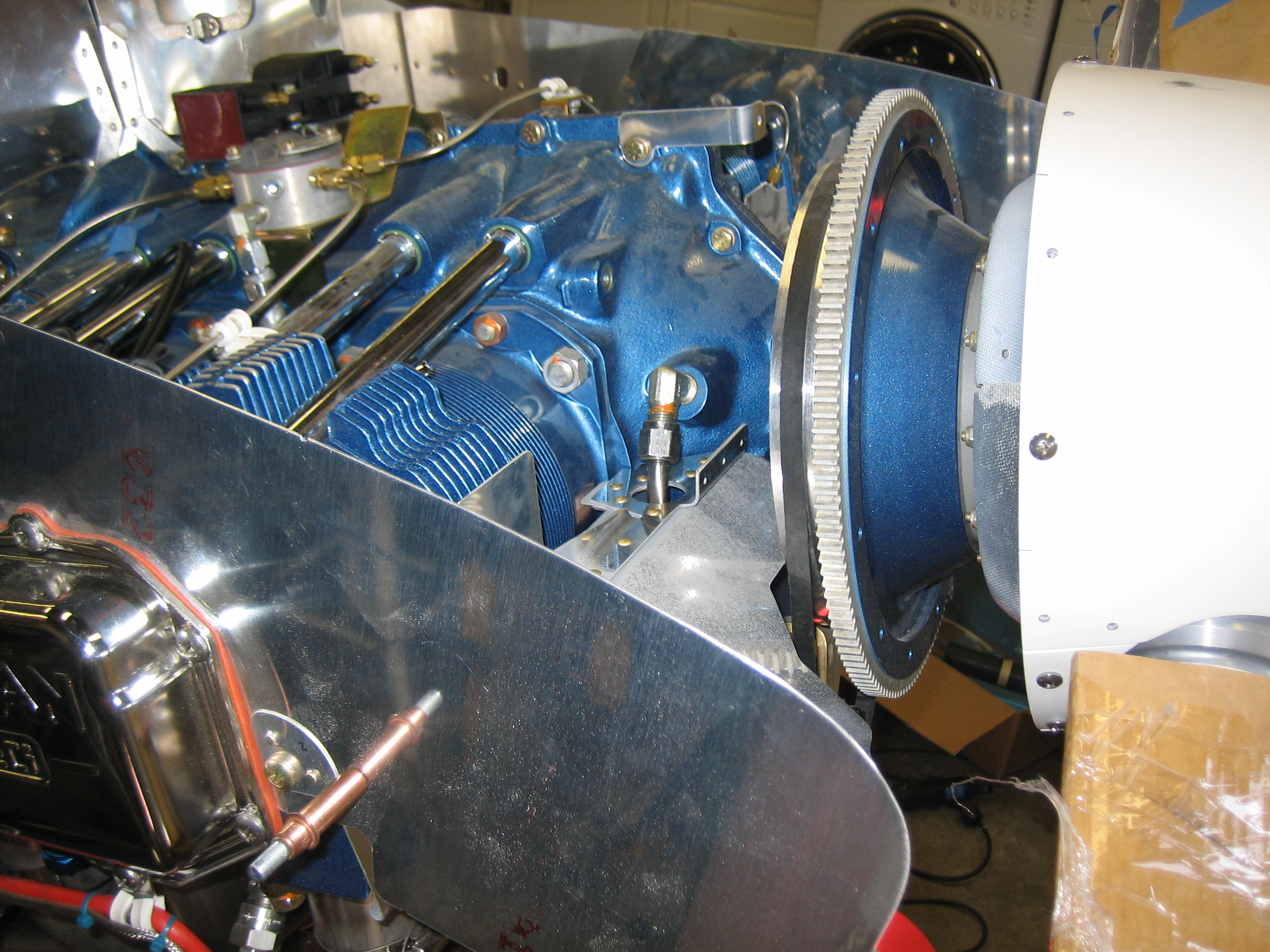
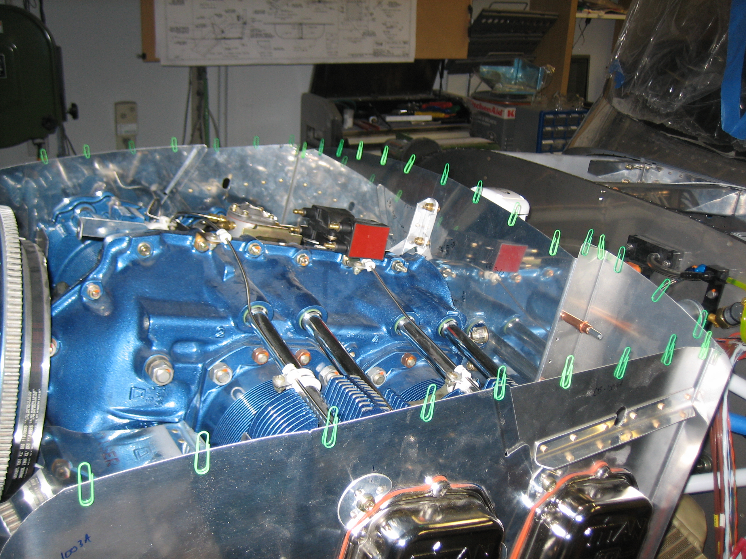
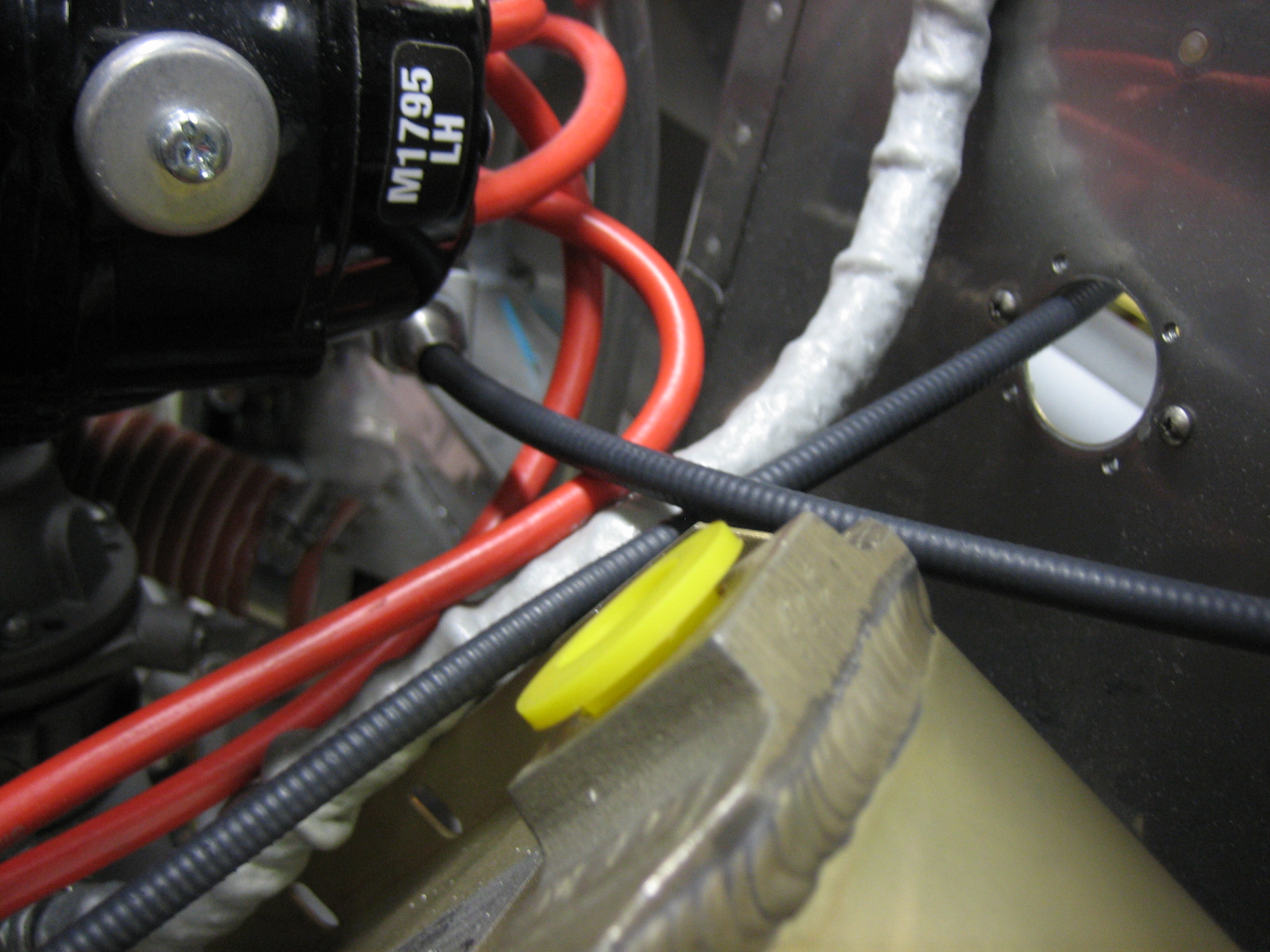
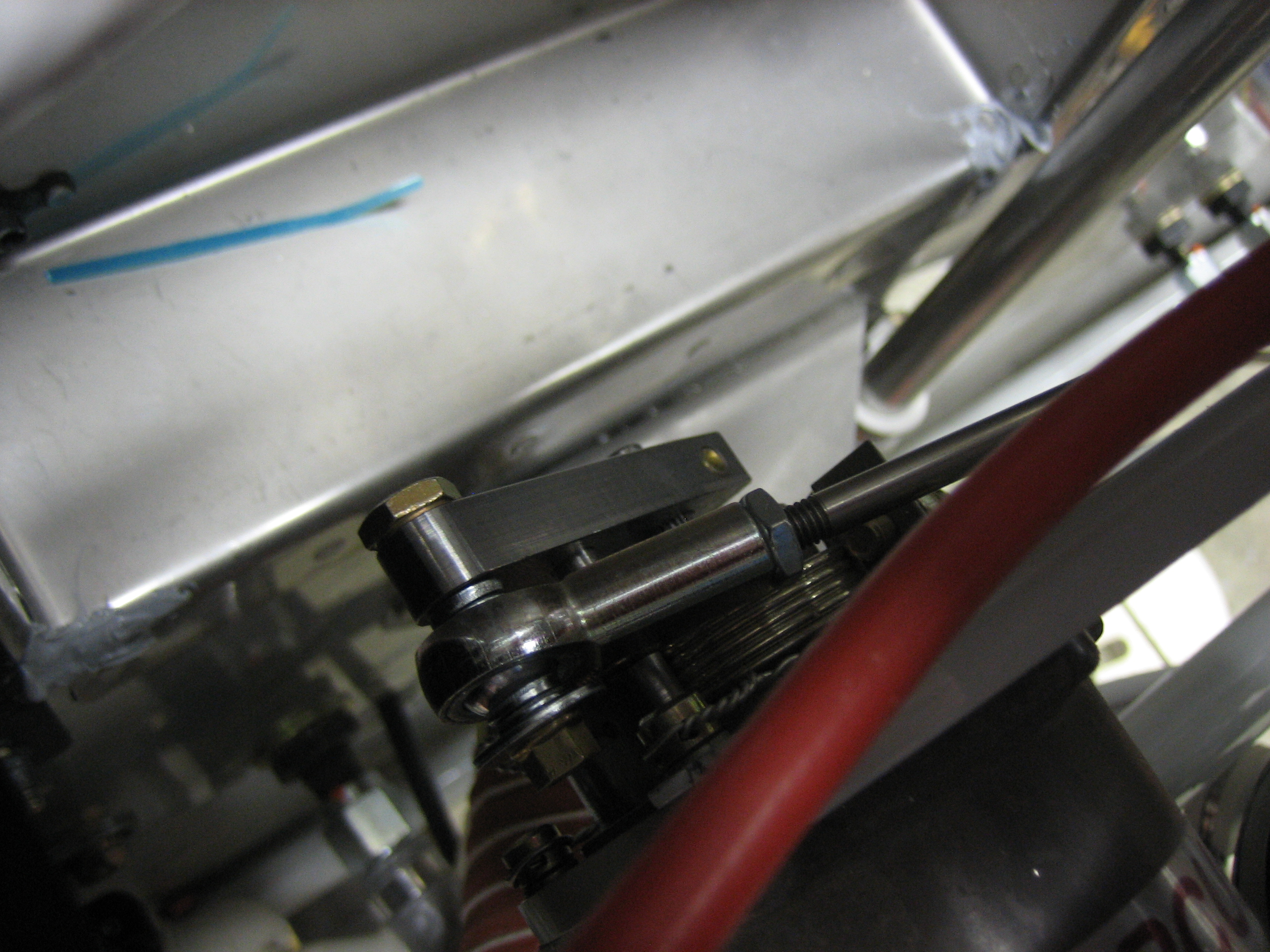
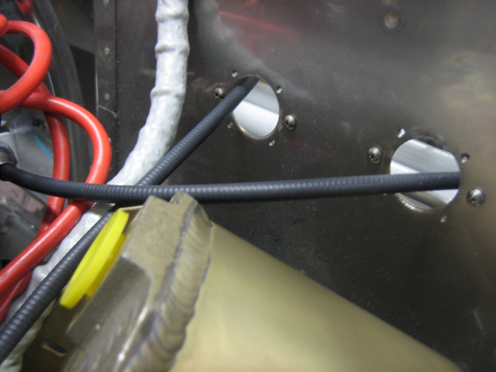
The prop cable penetrates the far left hole (right in this picture since we’re looking aft) at a pretty severe angle since it needs to mount to the governor on the back of the engine.

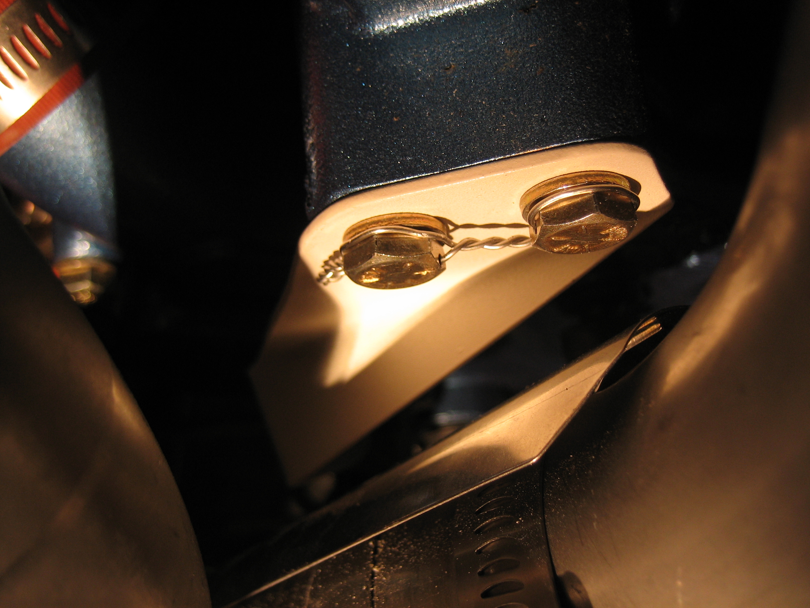
The end of the cable attaches to the governor control arm.  After some adjusting, the throw on the prop governor is perfect as well.  I do need to replace this bolt though.  It’s too short and I want to use a castle nut and cotter pin just like the other control cables.  I did have to reverse the bolt from the orientation specified in the plans since it’s just about impossible to insert/remove the bolt the other way since there is not enough space between the control arm and back end of the governor.