Heater Box, Vent Line, Baggage Floors

The stainless steel attachment hardware showed up from Aircraft Spruce today, to I gooped up the back of the heater box with the 2000ºF fire block sealant that came with this and bolted it to the firewall.  I probably spent more time cleaning off the excess that oozed out of the joint than I did actually attaching it.I have no doubts that it’s well sealed though.

Here is a shot on the inside.  The specified AN3C-4A bolts were a little long, so I had to stack up a couple of extra washers to be able to tighten them properly.  AN3C-3A bolts would have been perfect.  The stop nuts are MS21046C3.  I originally thought they sent me the wrong nuts because these looked like aluminum.  It turns out that these are silver plated.

I used the right vent line as a template and knocked the left line out in about 20 minutes.  I’ll probably wait until the subpanel is riveted in for good before installing these permanently.

Before installing the baggage and seat floors for good, I needed to take care of one last tasks that would be impossible once they’re riveted on.  I have two conduit runs under these floors that pass through the F-705 and F-706 bulkheads.  Vibration can cause the aluminum to cut through the conduit over time, so I used some E6000 adhesive to secure the conduit to the bulkheads.  This will prevent any relative motion that could damage the conduit.

Finally, I put the baggage floors on for good and pulled all of the blind rivets.  I really wish I had bought a pneumatic rivet puller; my hand is killing me.  If you’re just getting started, do yourself a favor and spend the $35 to pick up one from Harbor Freight.

I still have to install the nutplates along the back and center tunnel, but I’m beat.

Engine Arrived!

My engine shipped last friday and arrived at Apple’s loading dock this afternoon.  The crate is bigger than I expected at about 3’x4′ and about 2.5′ tall.  According to the shipping documents, it weighs 400lbs.

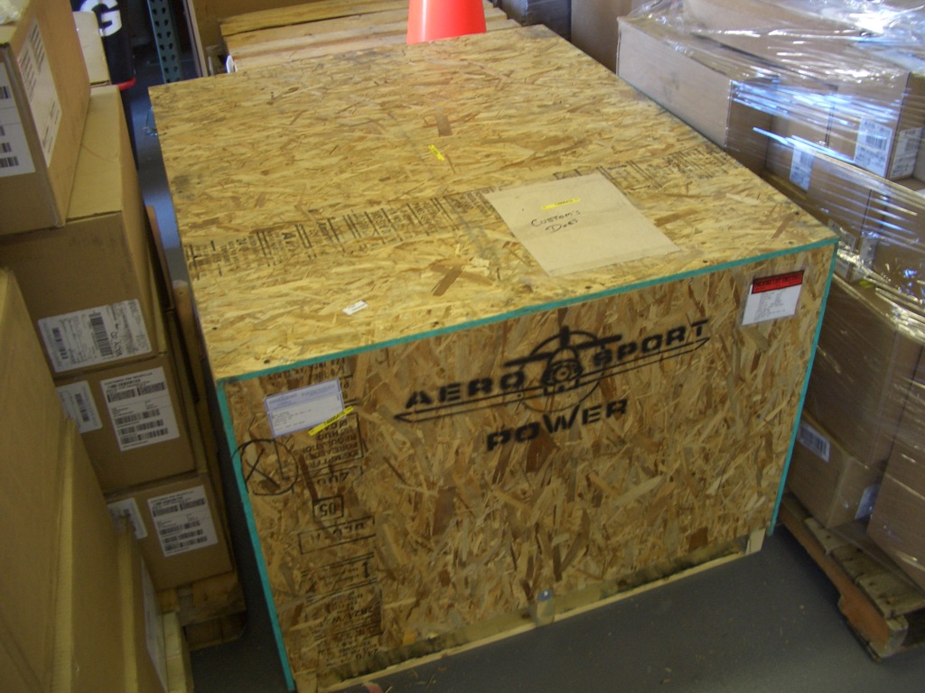
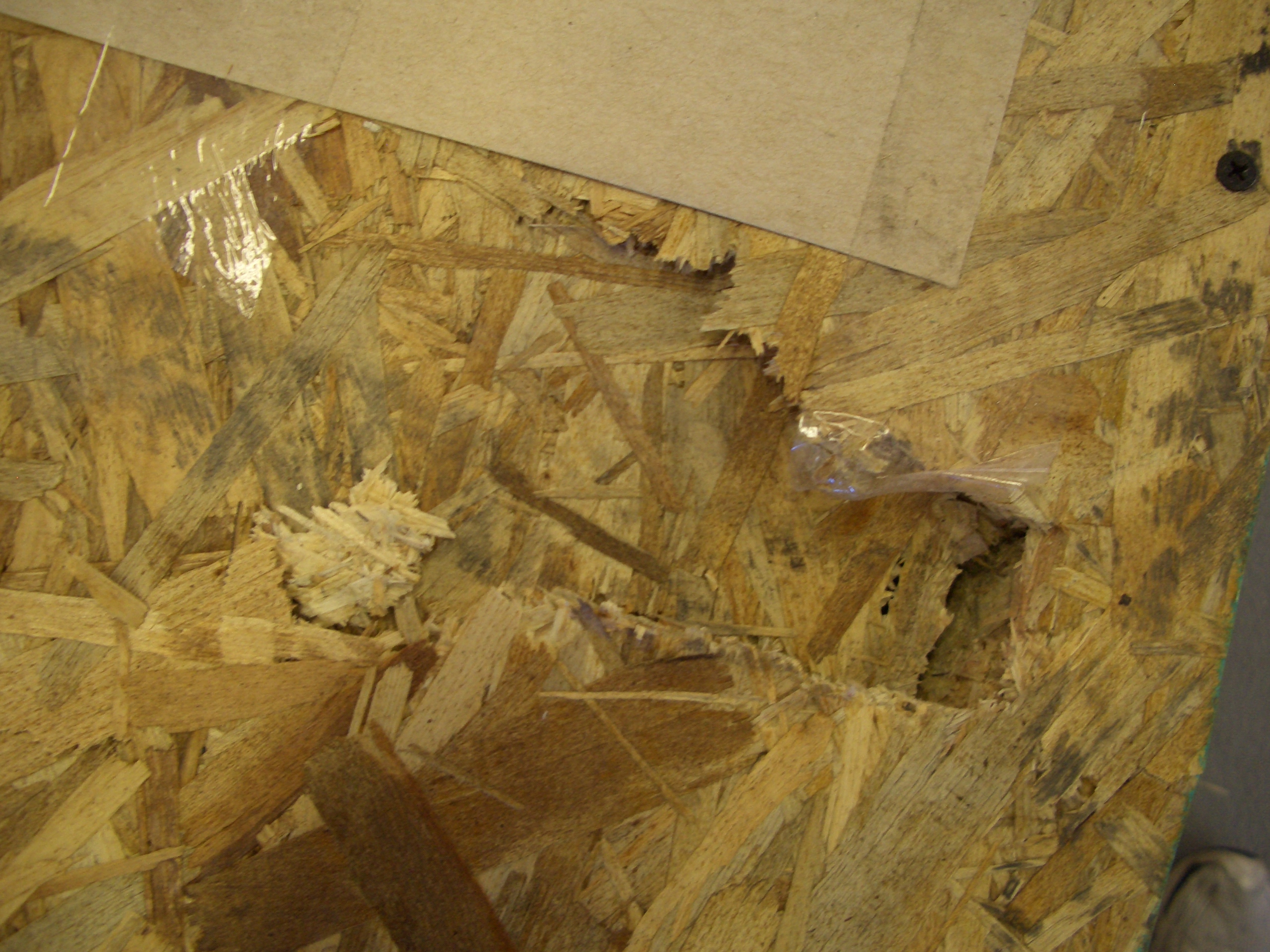
There was a little damage to the top of the crate near one end.  Probably something that was placed on top of this crate that broke through.  Hopefully there’s no damage to the components.

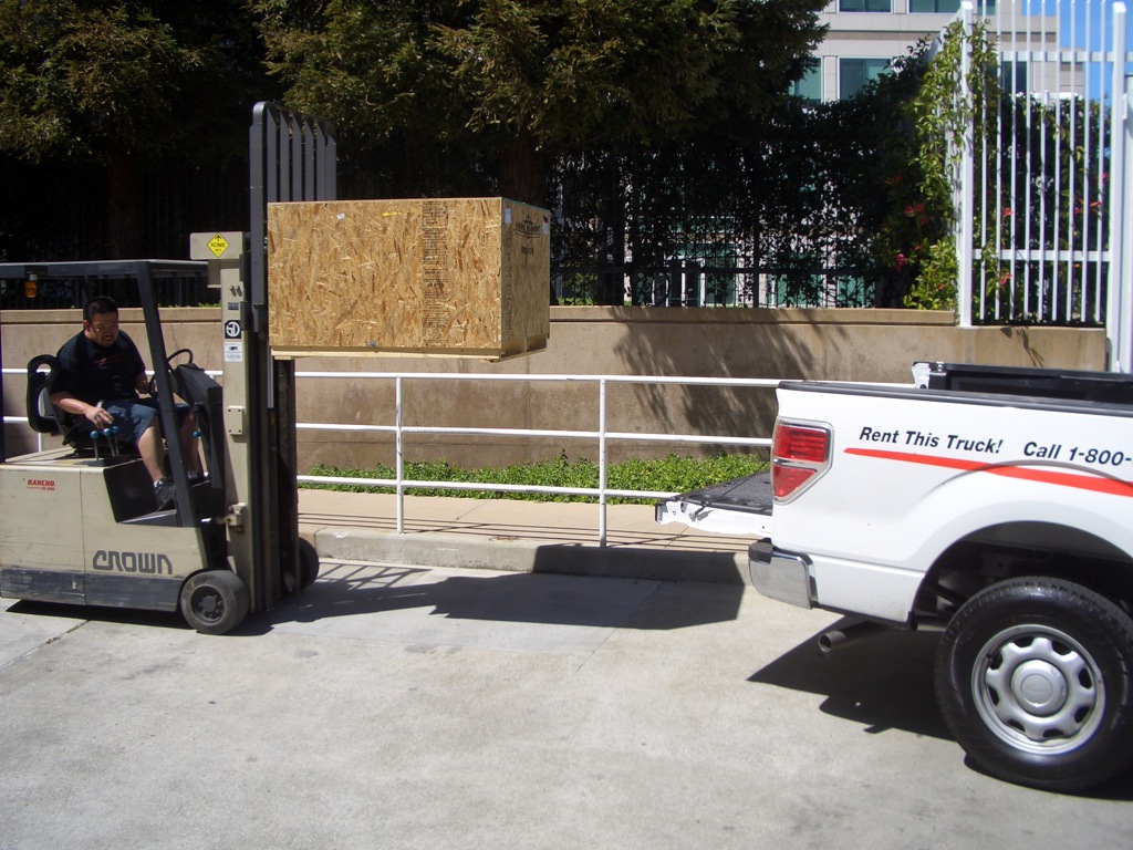
I rented a U-Haul pickup and the receiving guys loaded it into the back with their forklift.

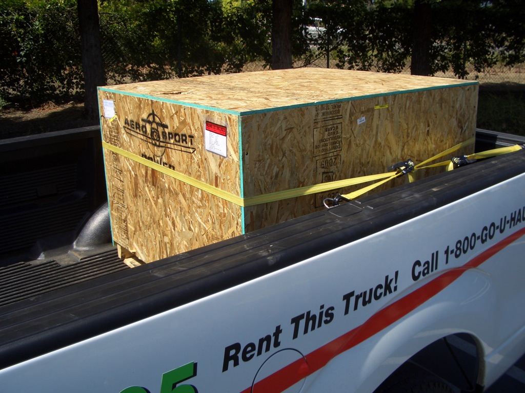
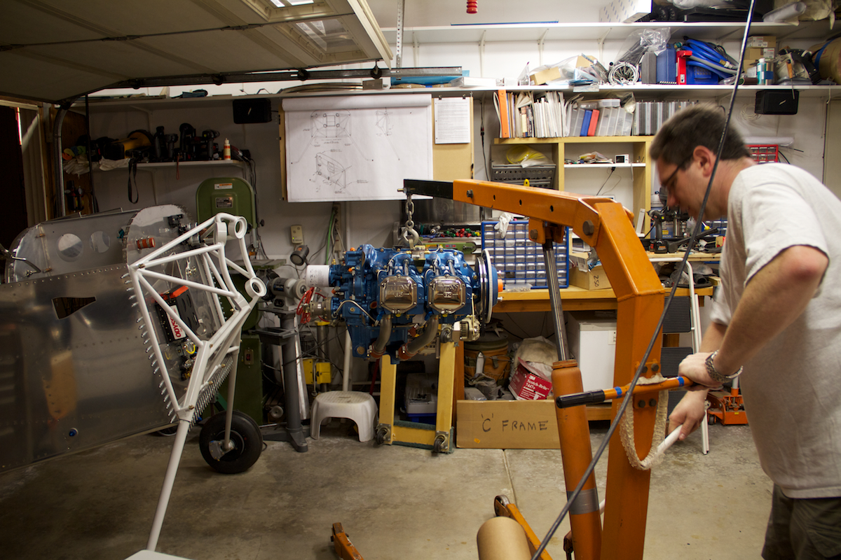
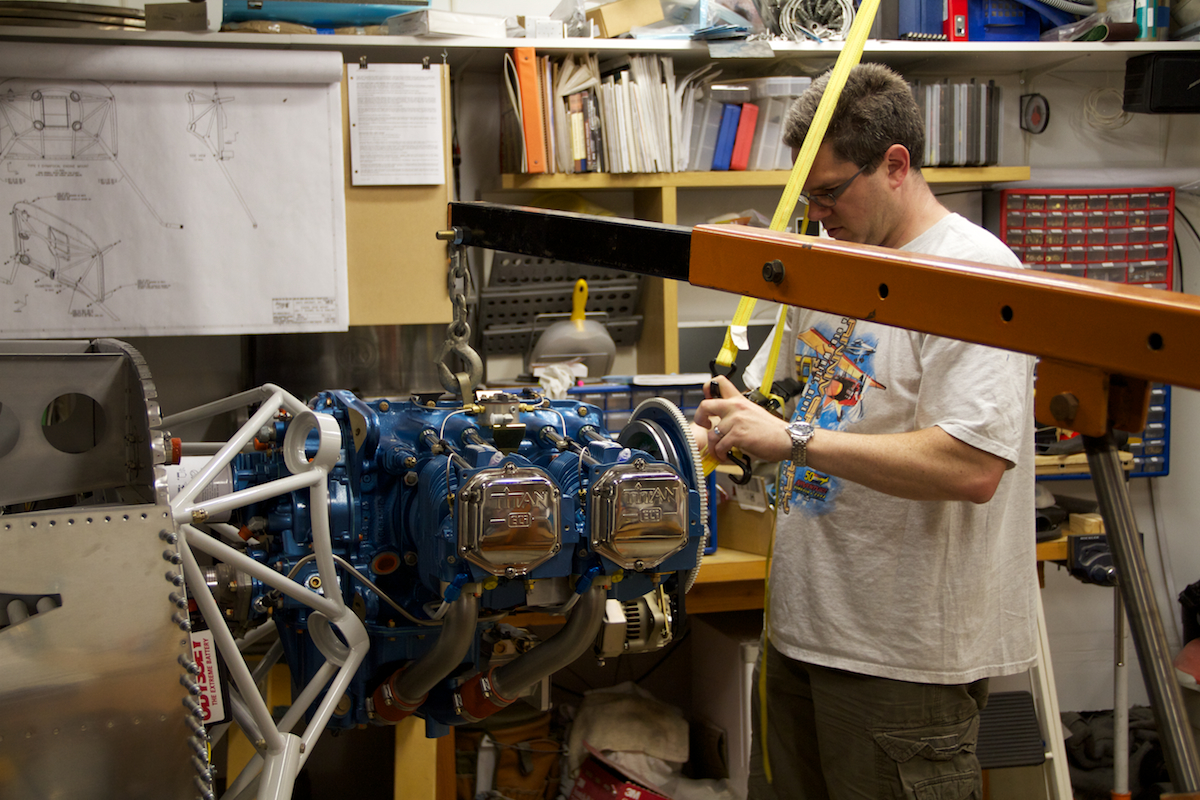
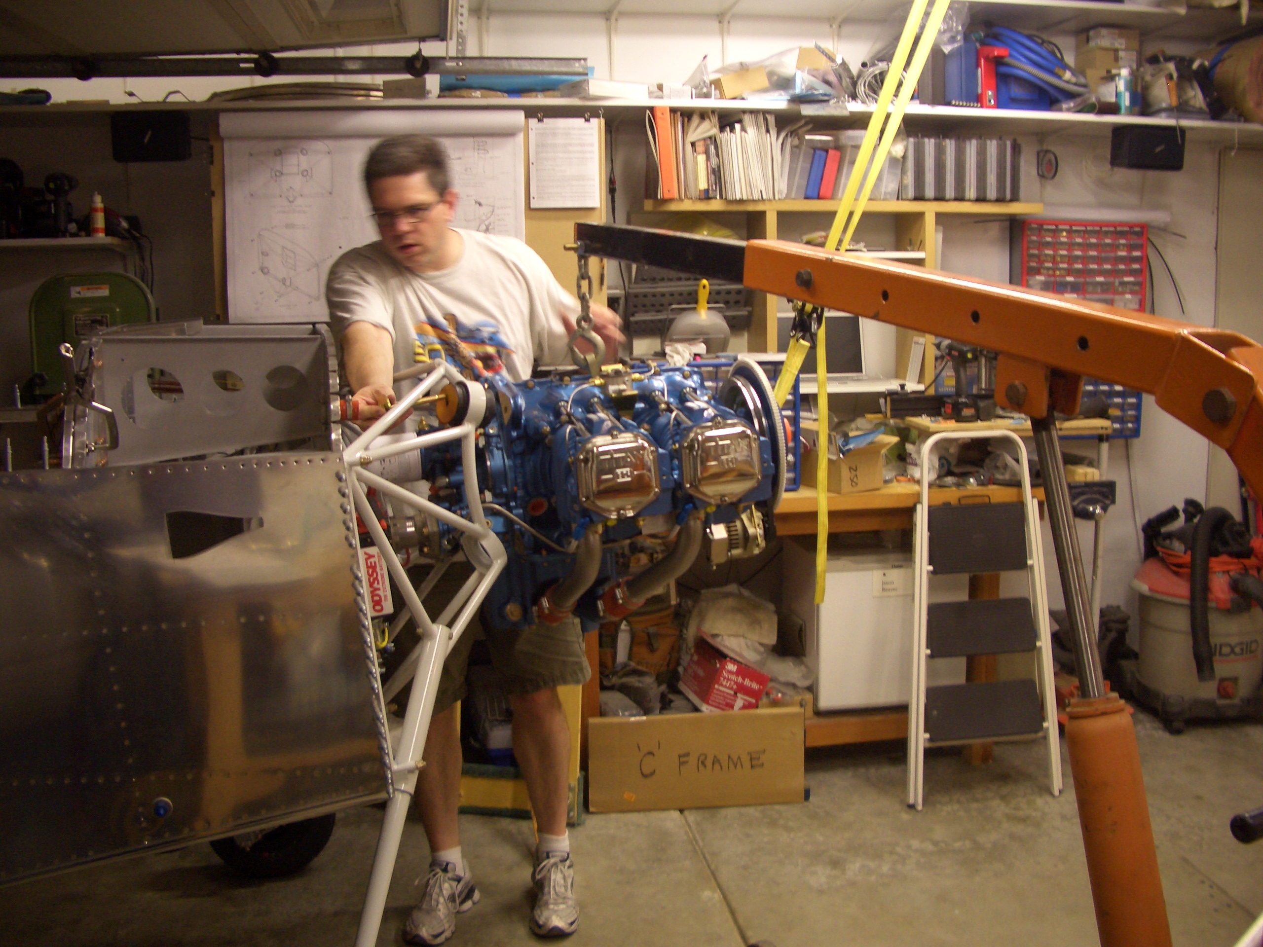
Here’s the crate strapped in and ready for the ride to my house.  My friend Josh from work helped me run this home and unload it with an engine hoist.

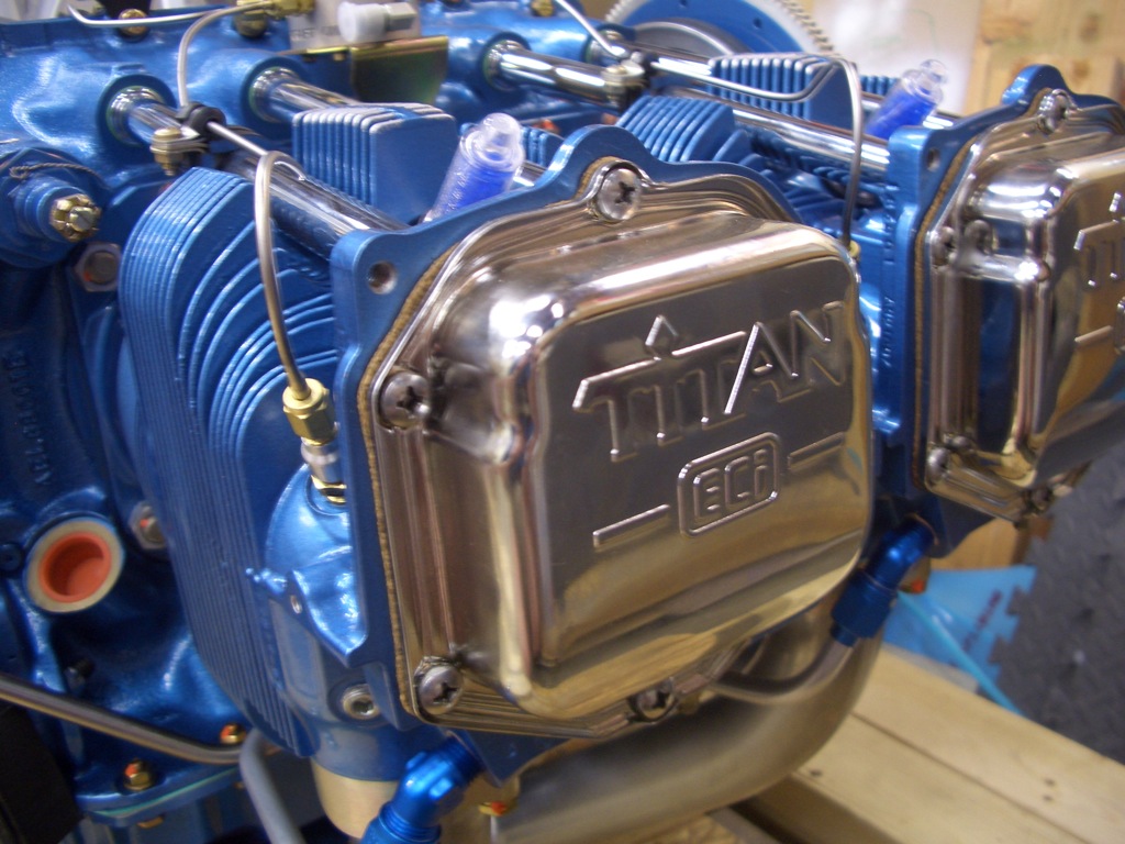
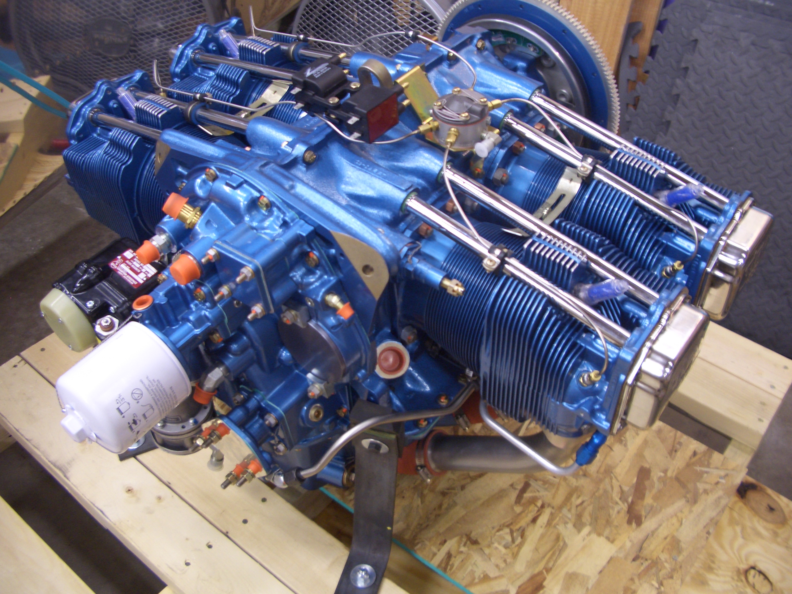
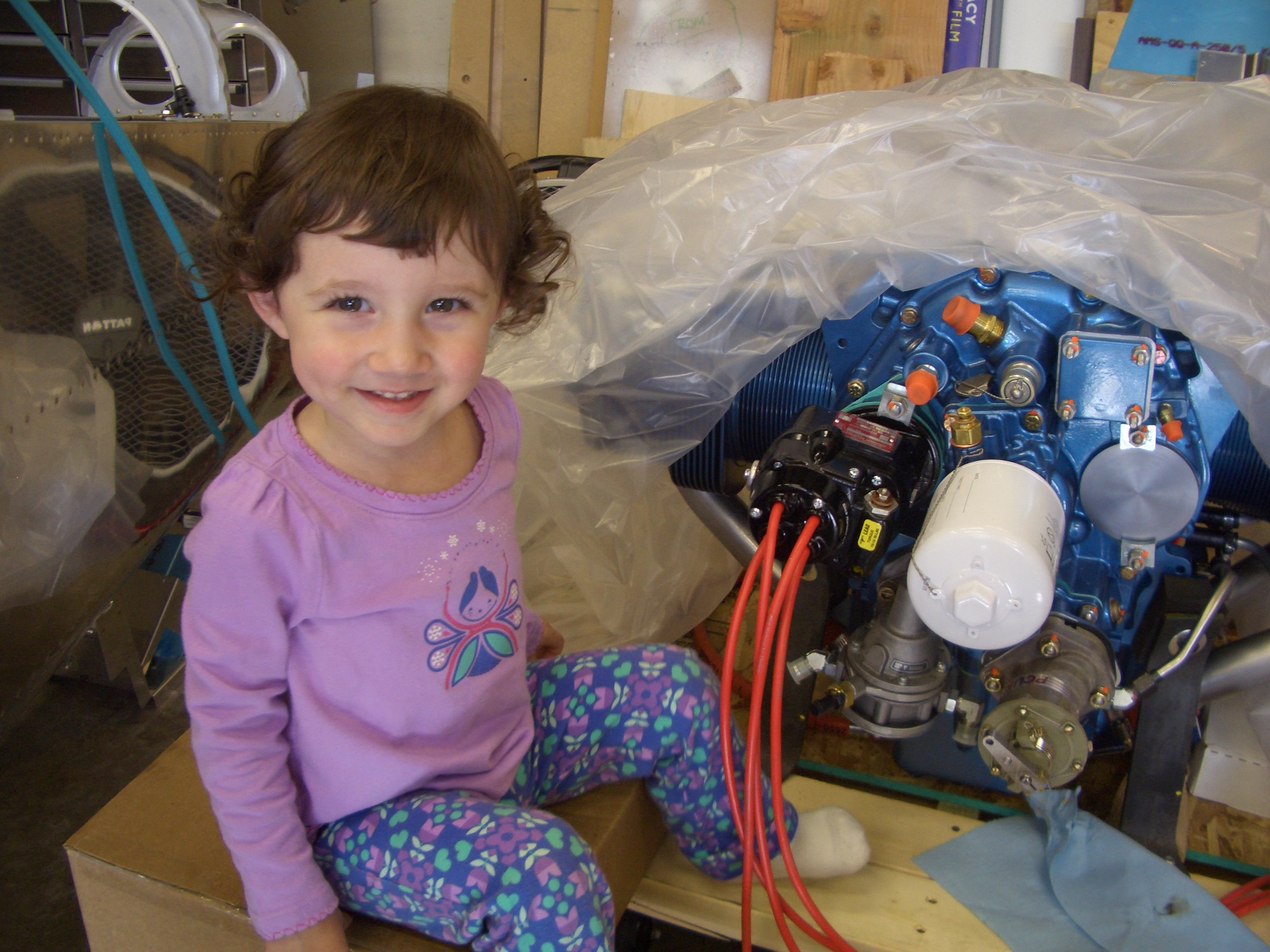
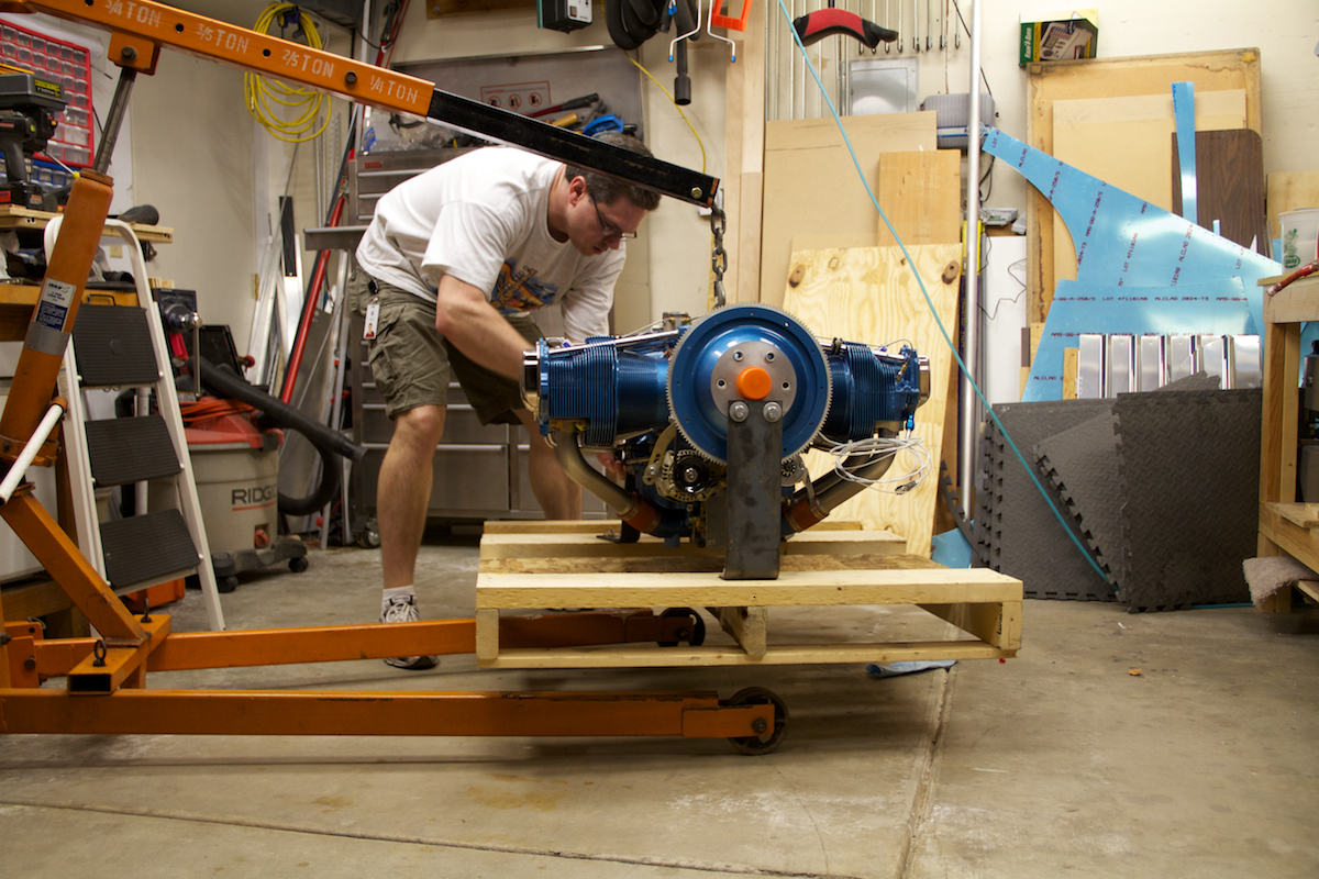
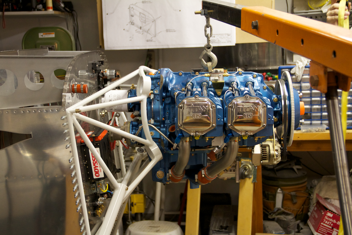
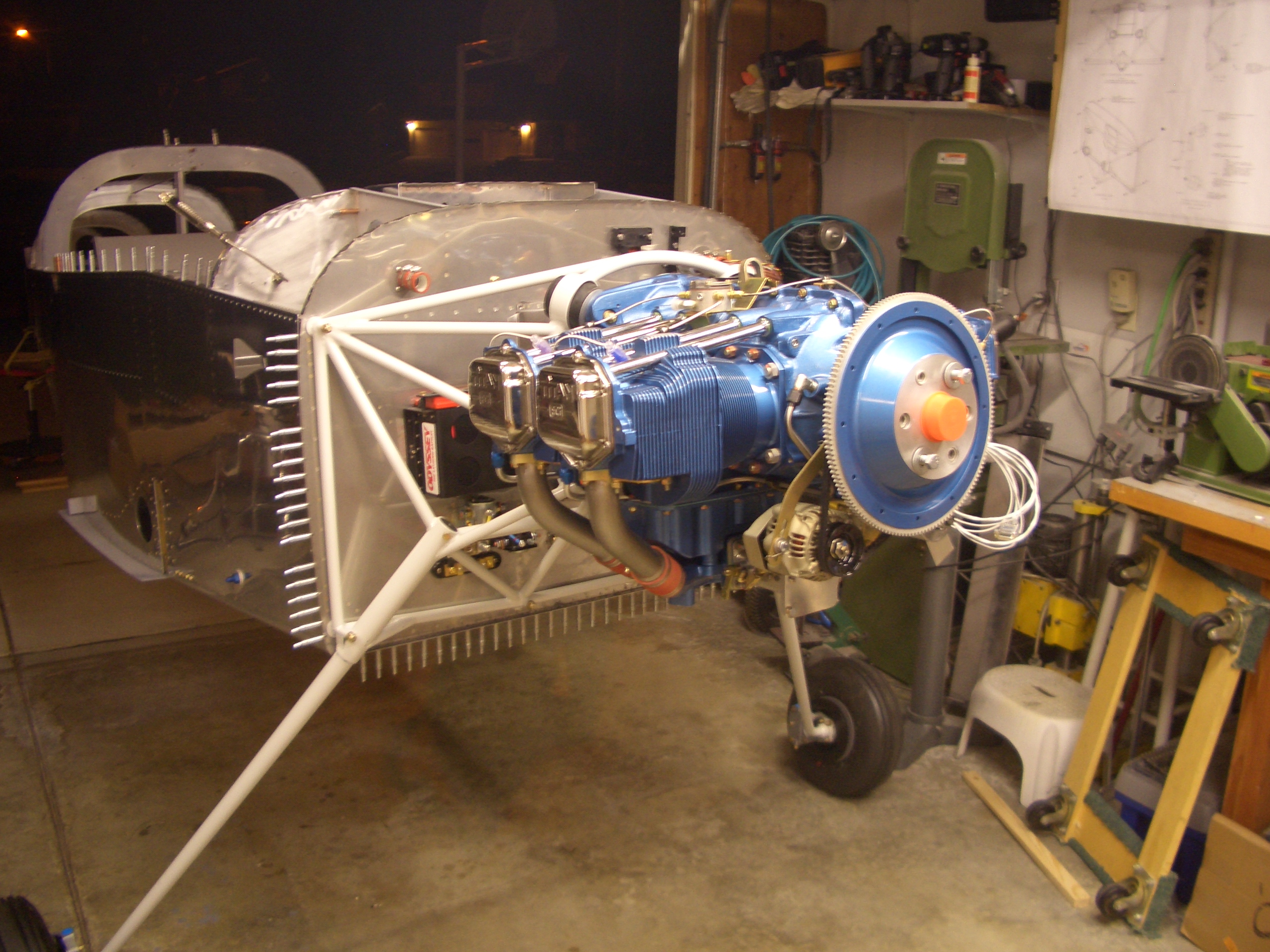
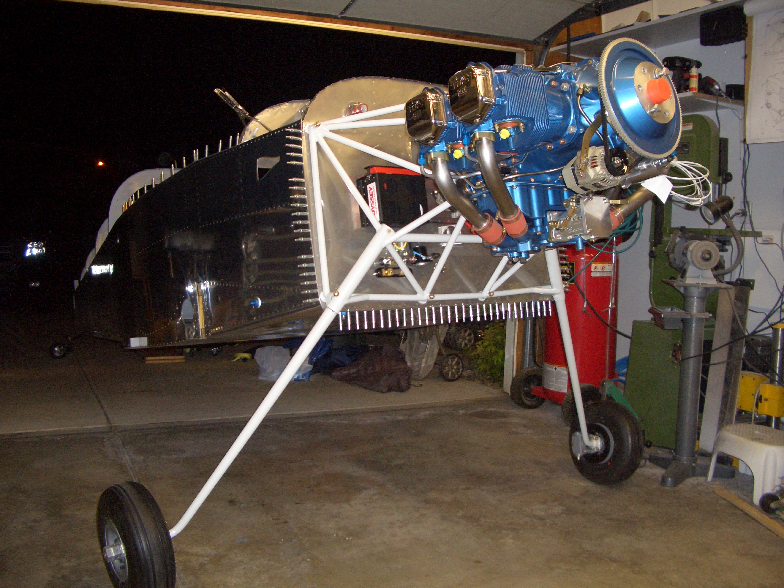
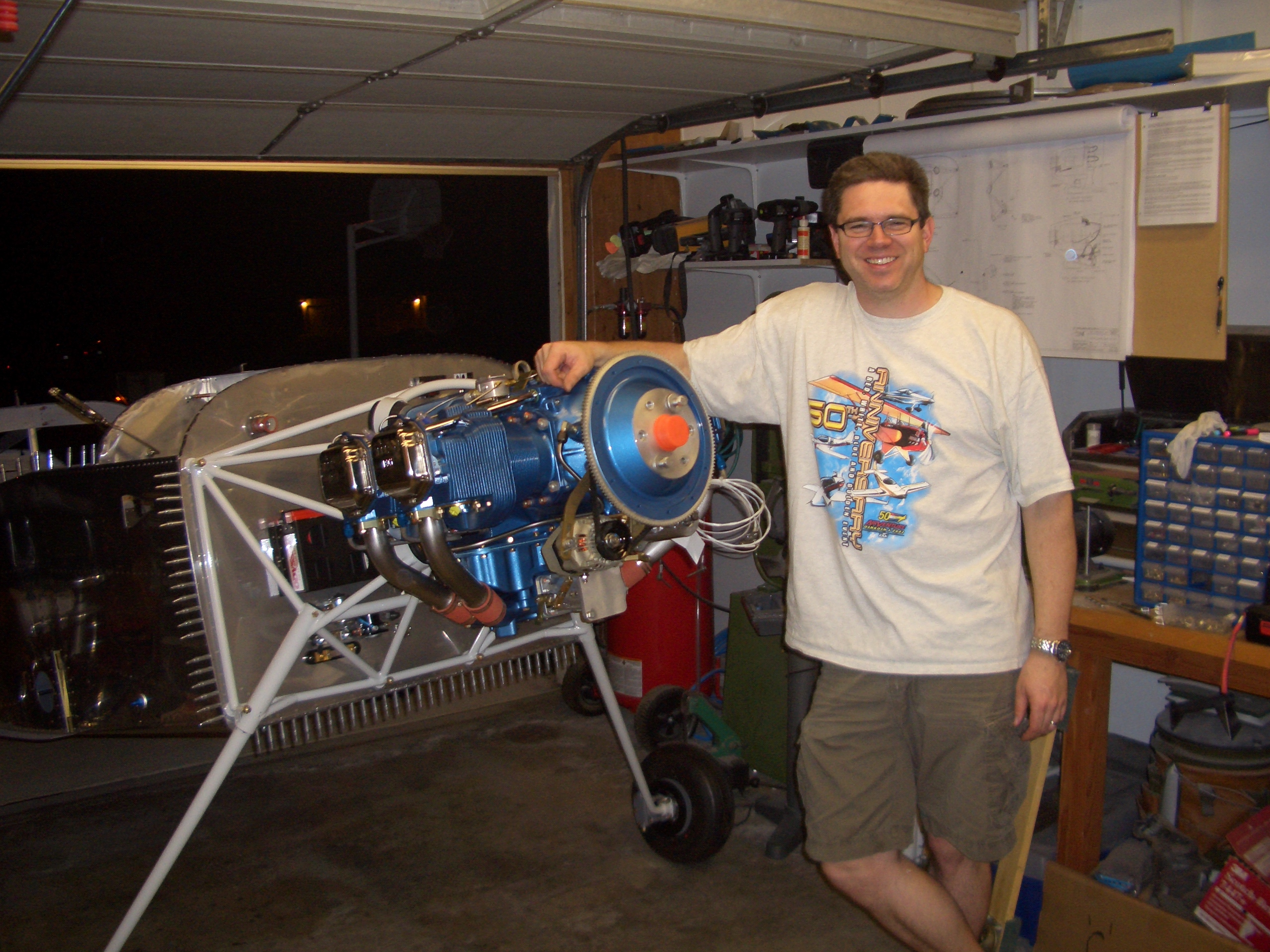
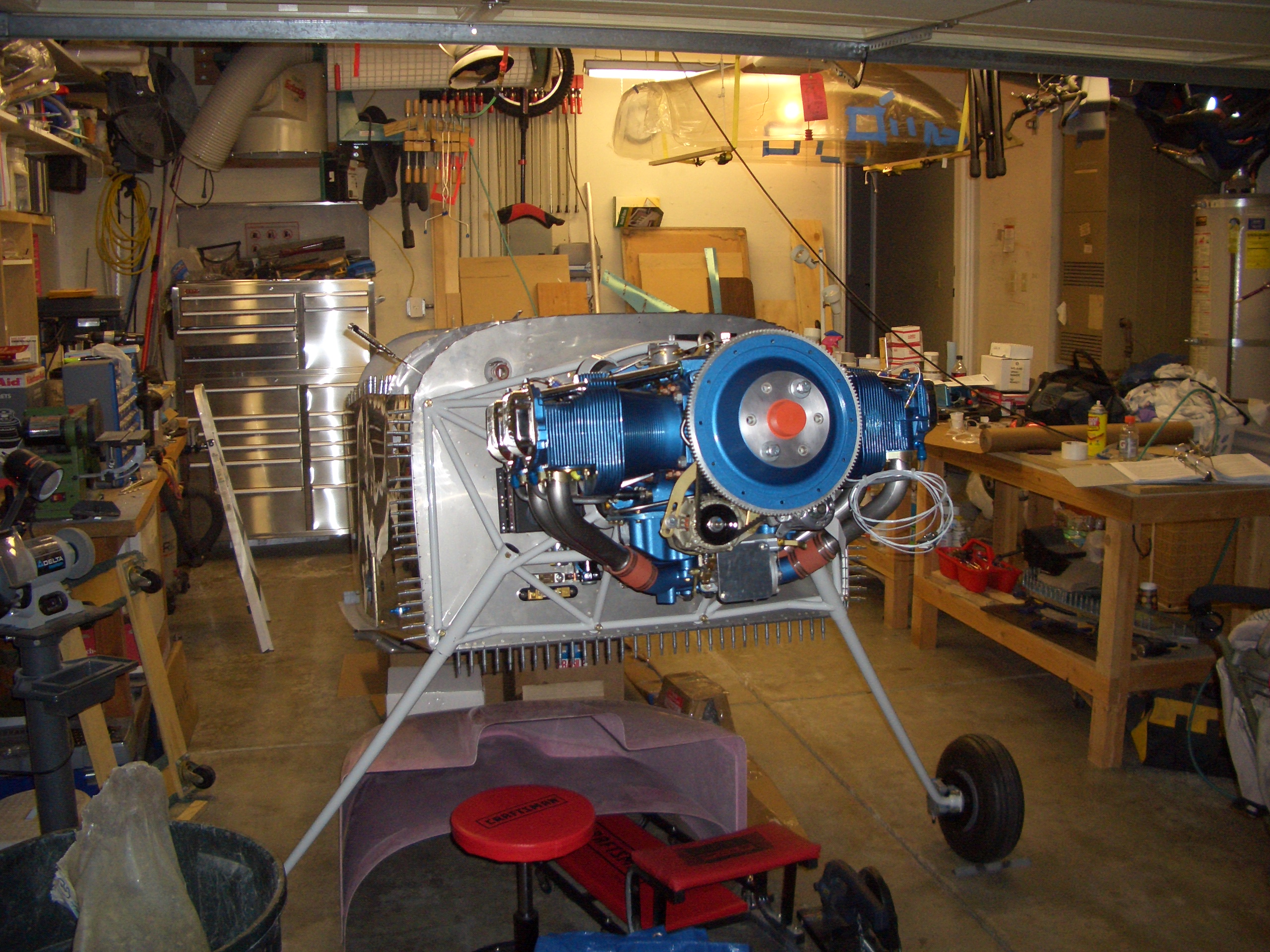
After work, I removed the crate (though the engine is still on the forklift pallet).  The engine looks fantastic.  It’s painted metallic blue (one of their stock colors) with chrome push rod tubes and valve covers.  This is an Aero Sport Power IO-375 engine with a Superior cold air induction sump.  It dyno’d at 196-198 hp on the test stand.

Aero Sport builds these from ECI components.

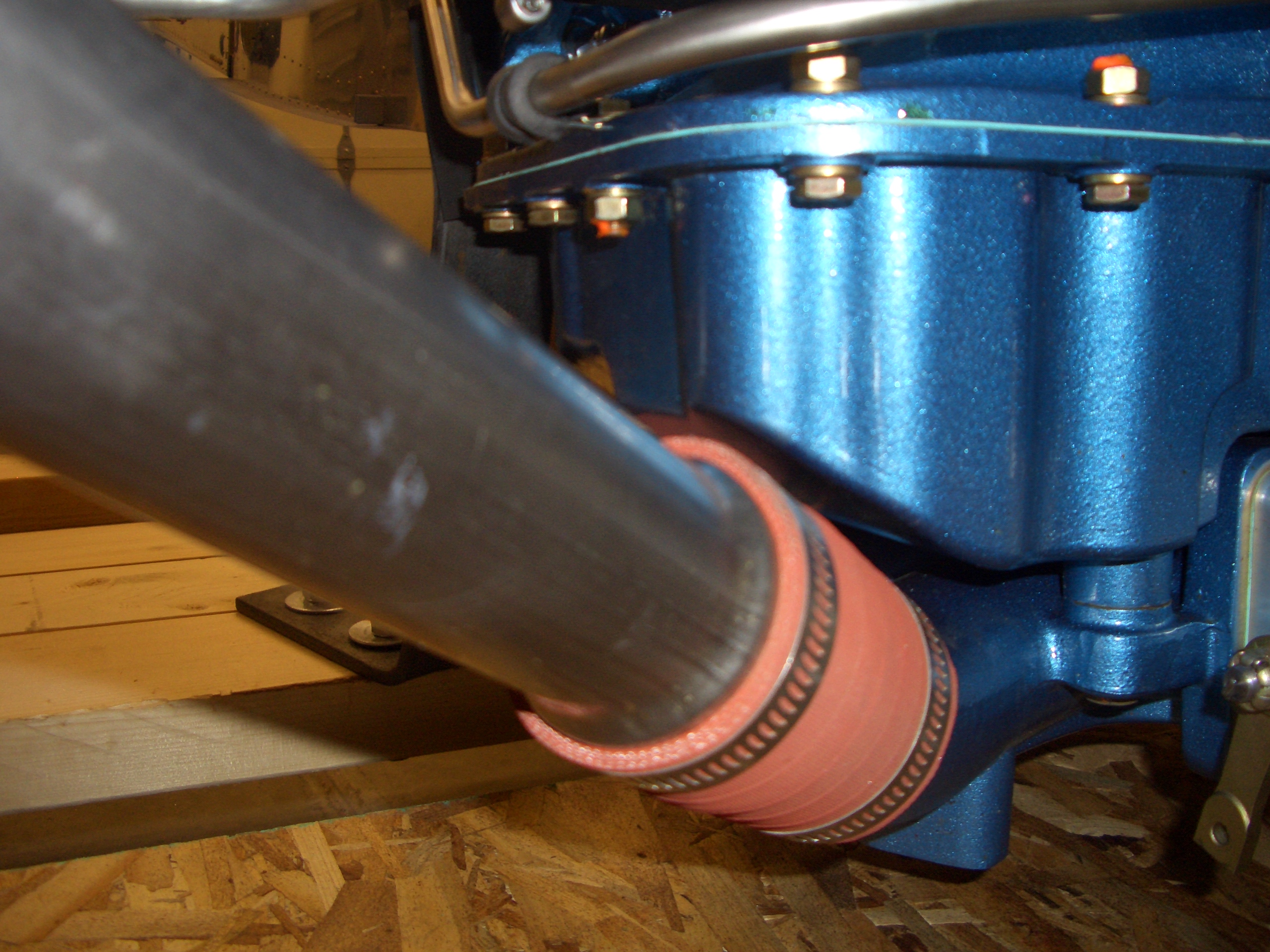
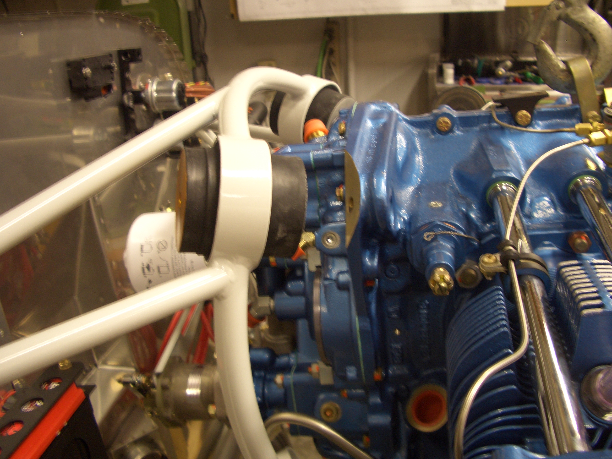
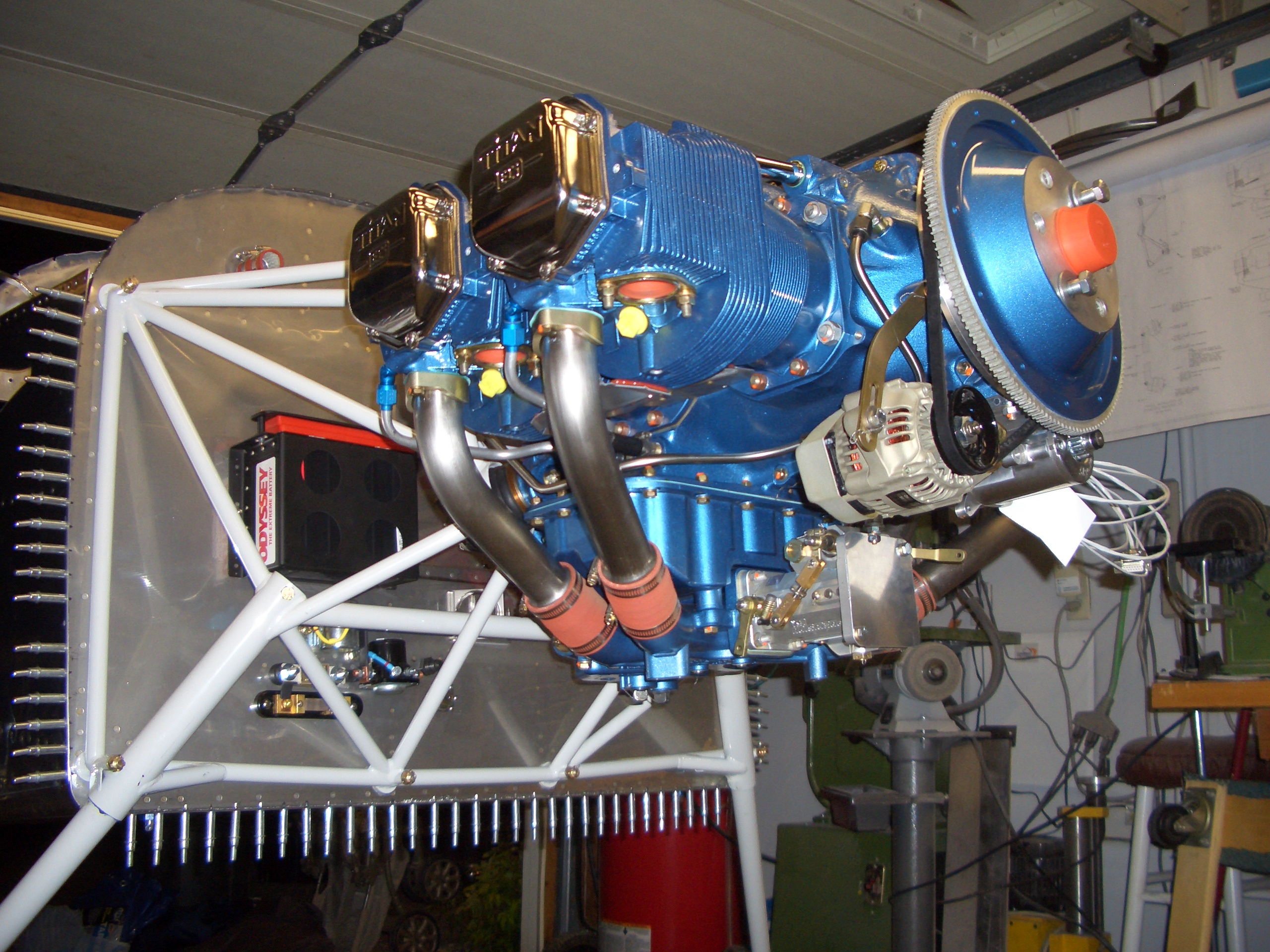
Here’s the Superior cold air sump.  You can sort of see that the intake tubes don’t run through the oil pan which keeps the intake air cooler than traditional sumps.  The intake tubes are stainless steel (just like the exhaust pipes will be).

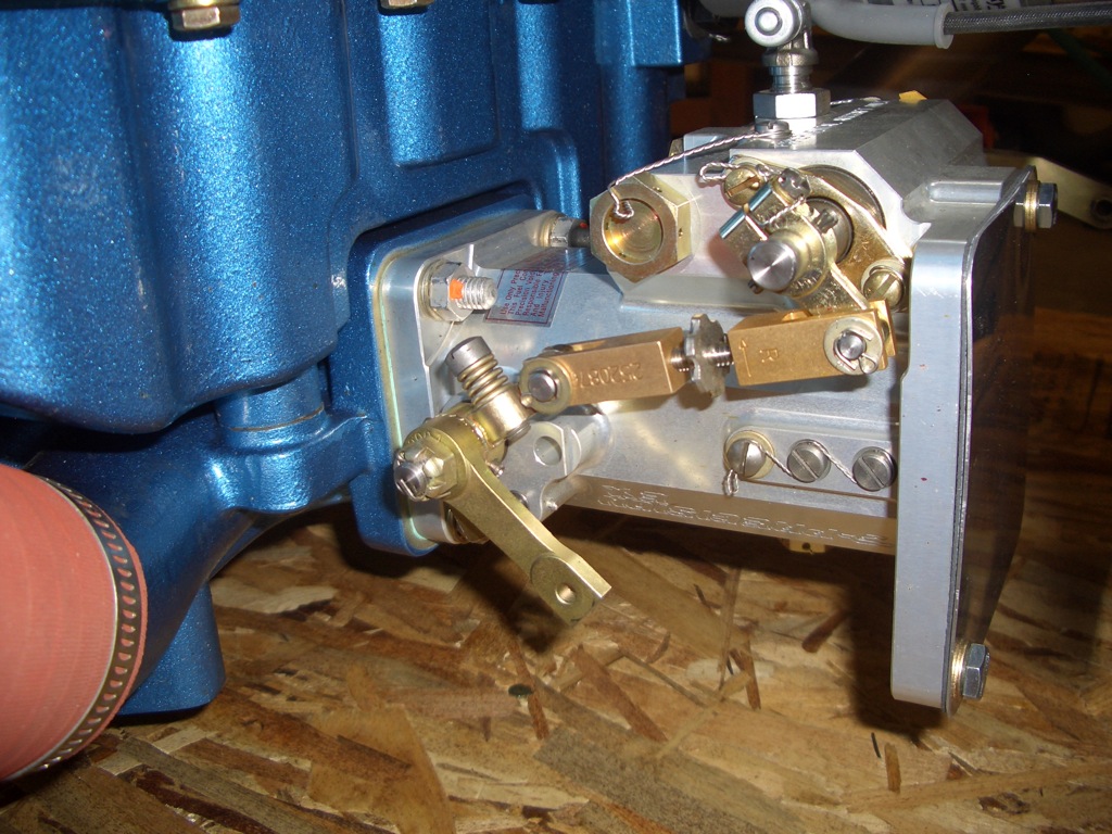
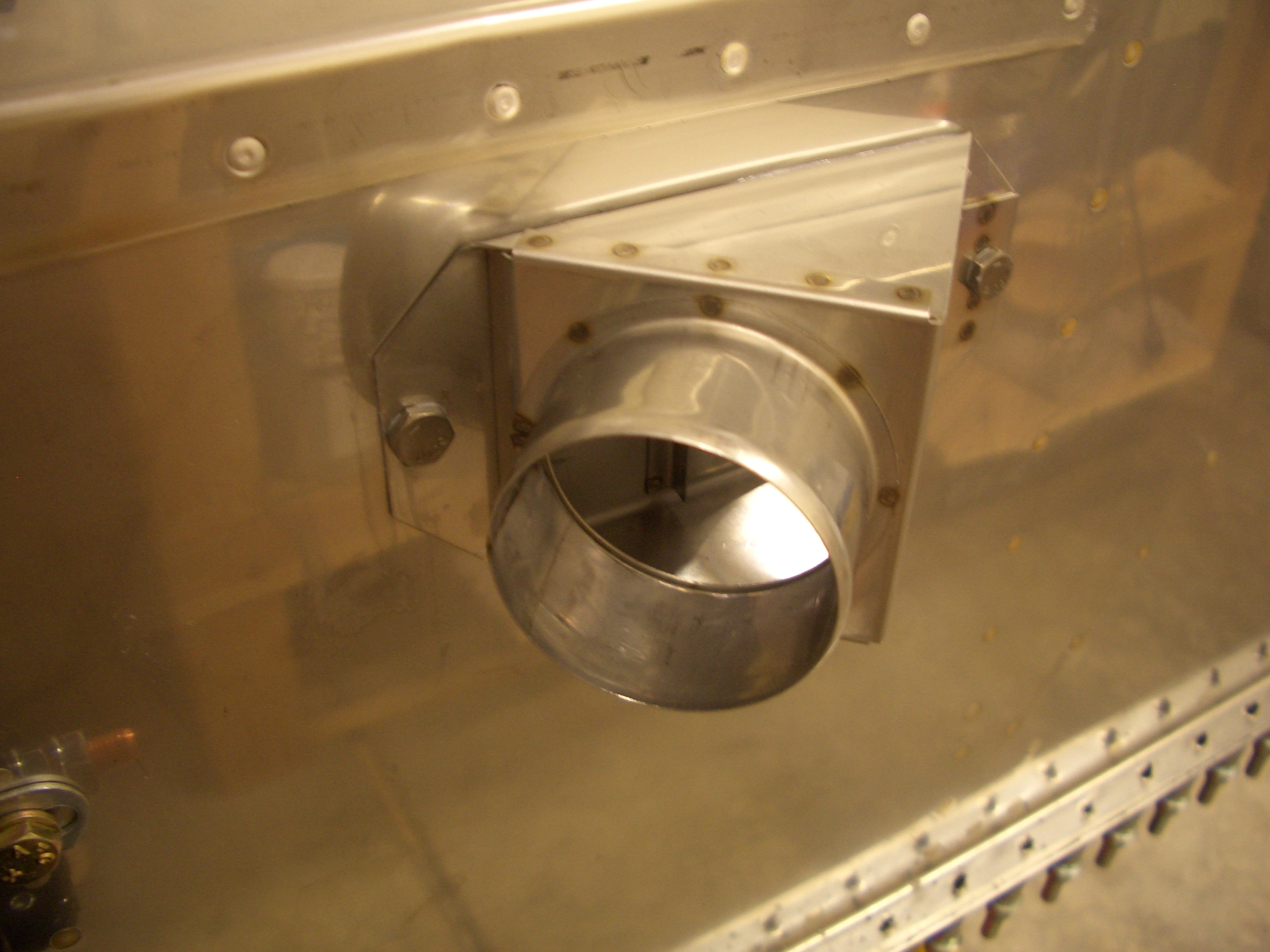
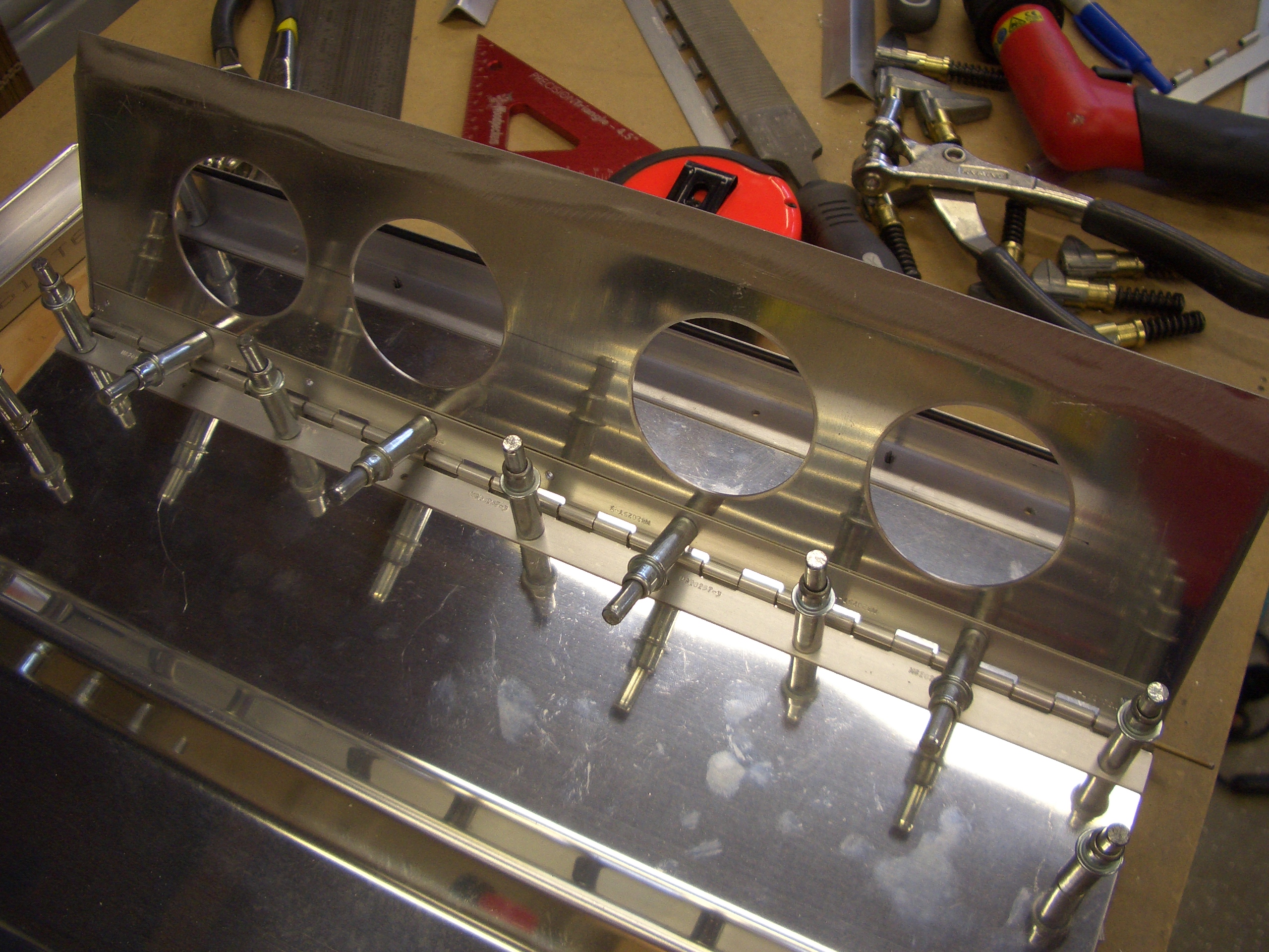
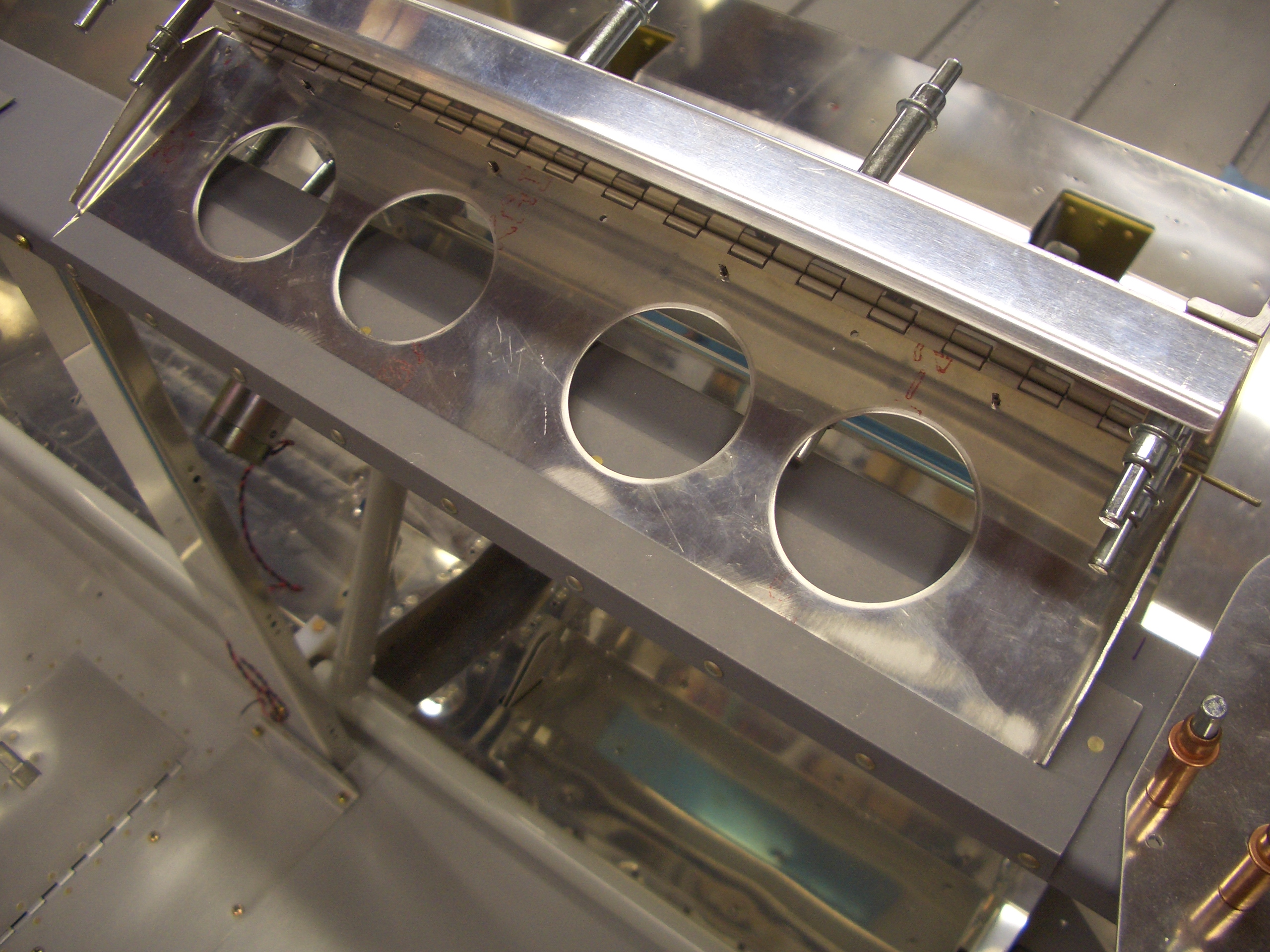
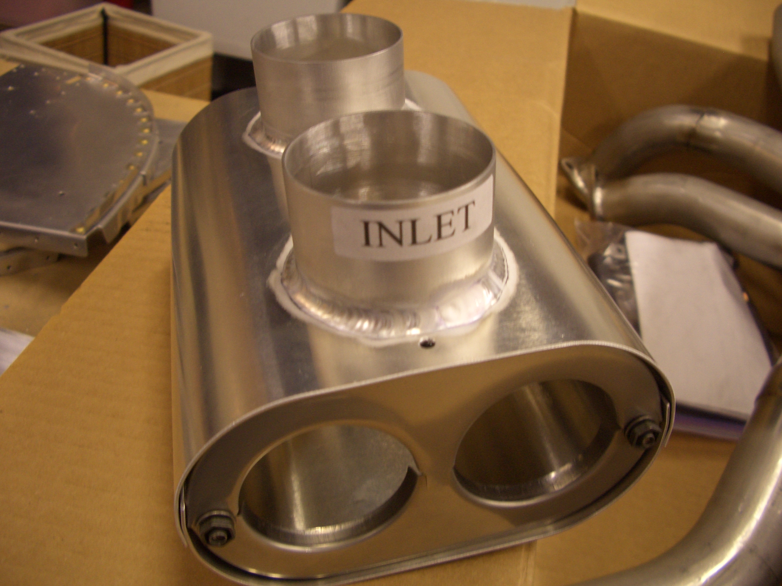
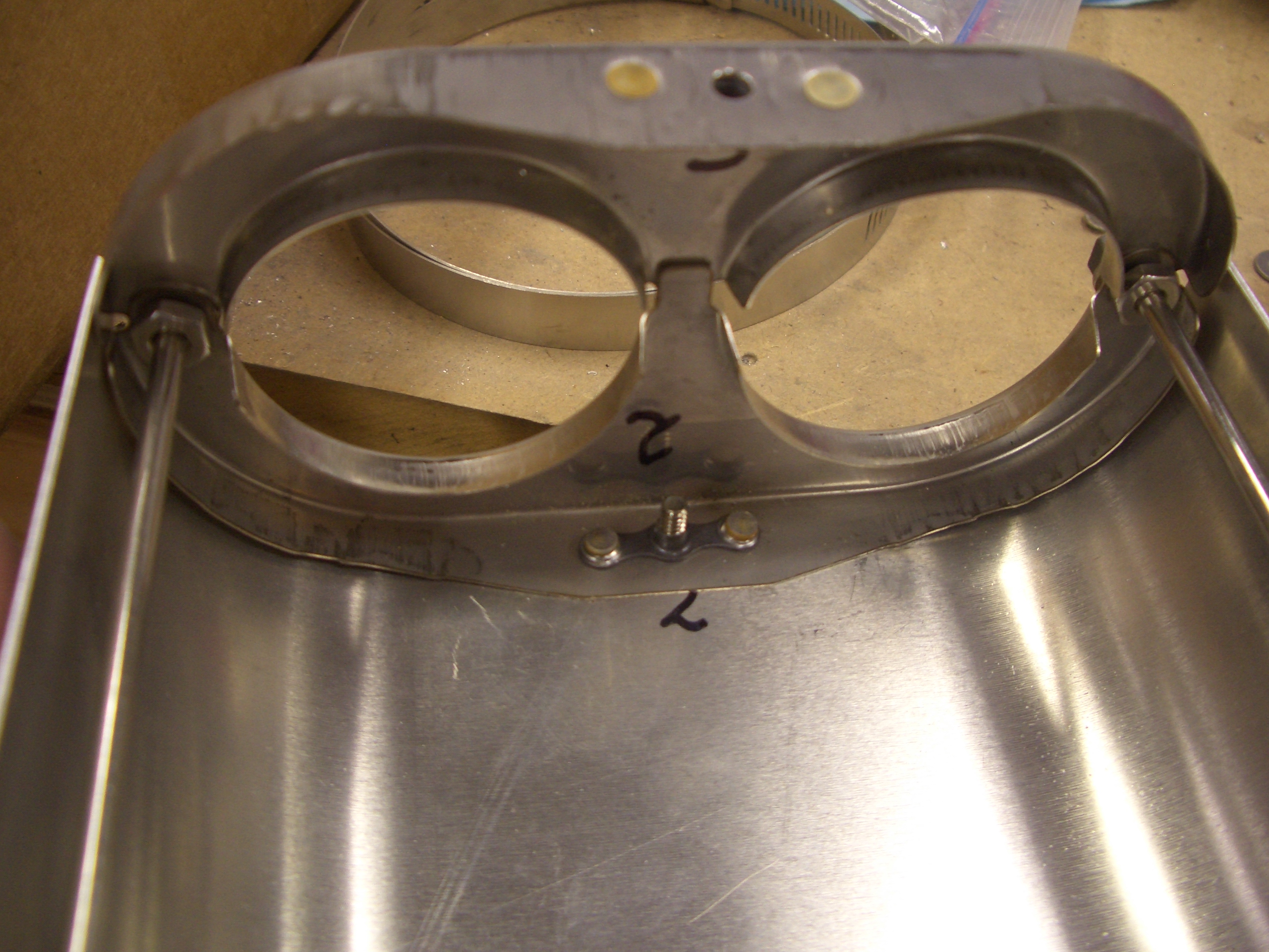
This is the Silver Hawk EX fuel injection servo.  Intake air will come through the opening covered by the plate on the right.

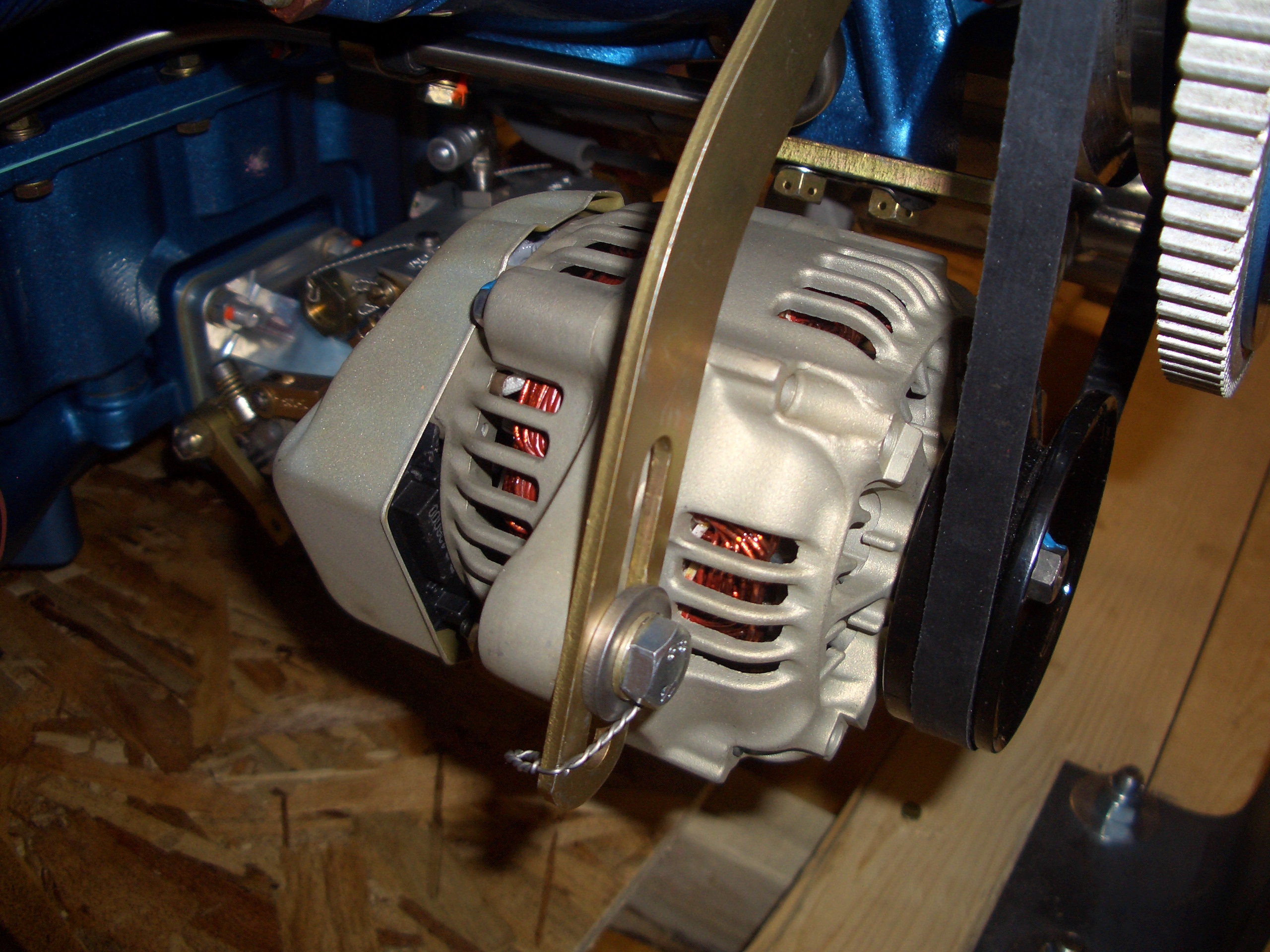
I also ordered a B&C Products 40 amp alternator that was preinstalled.

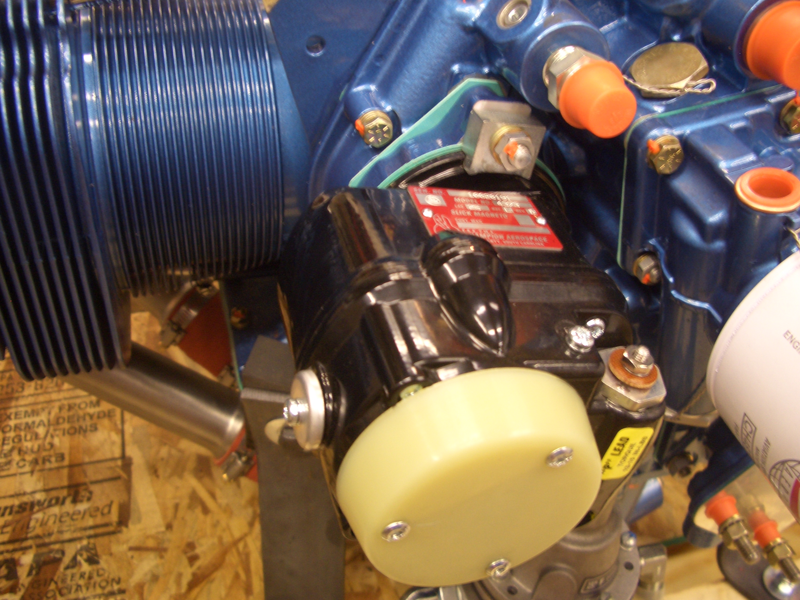
Traditional aircraft engine run dual magnetos for the ignition system.  I’m using an electronic ignition for one set of spark plugs, but I’m using a traditional mag for the other set.  This provides two independent ignition systems, one of which is not dependent on the electrical system.

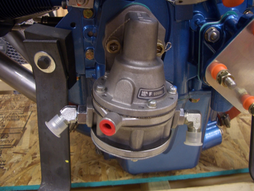
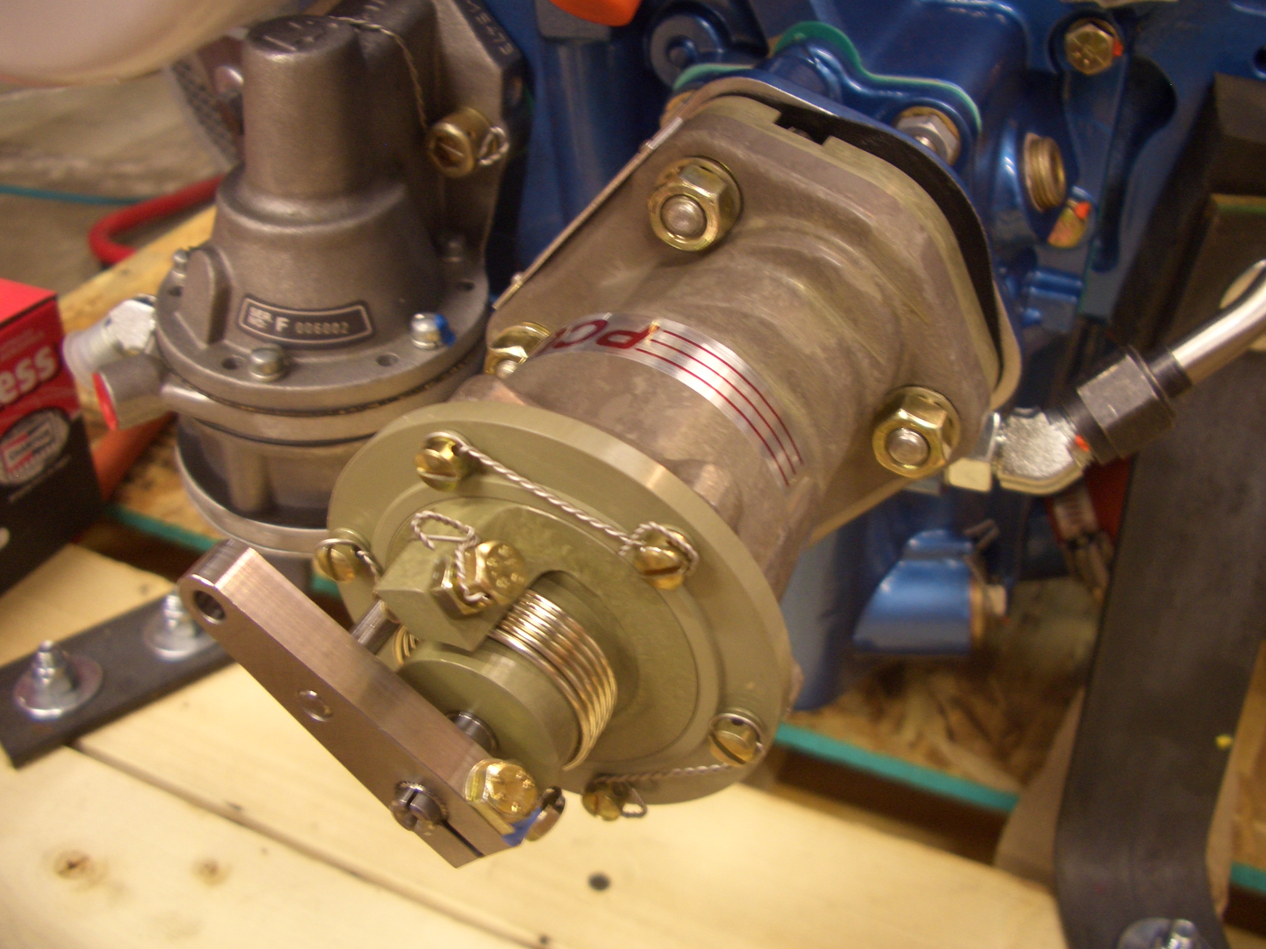
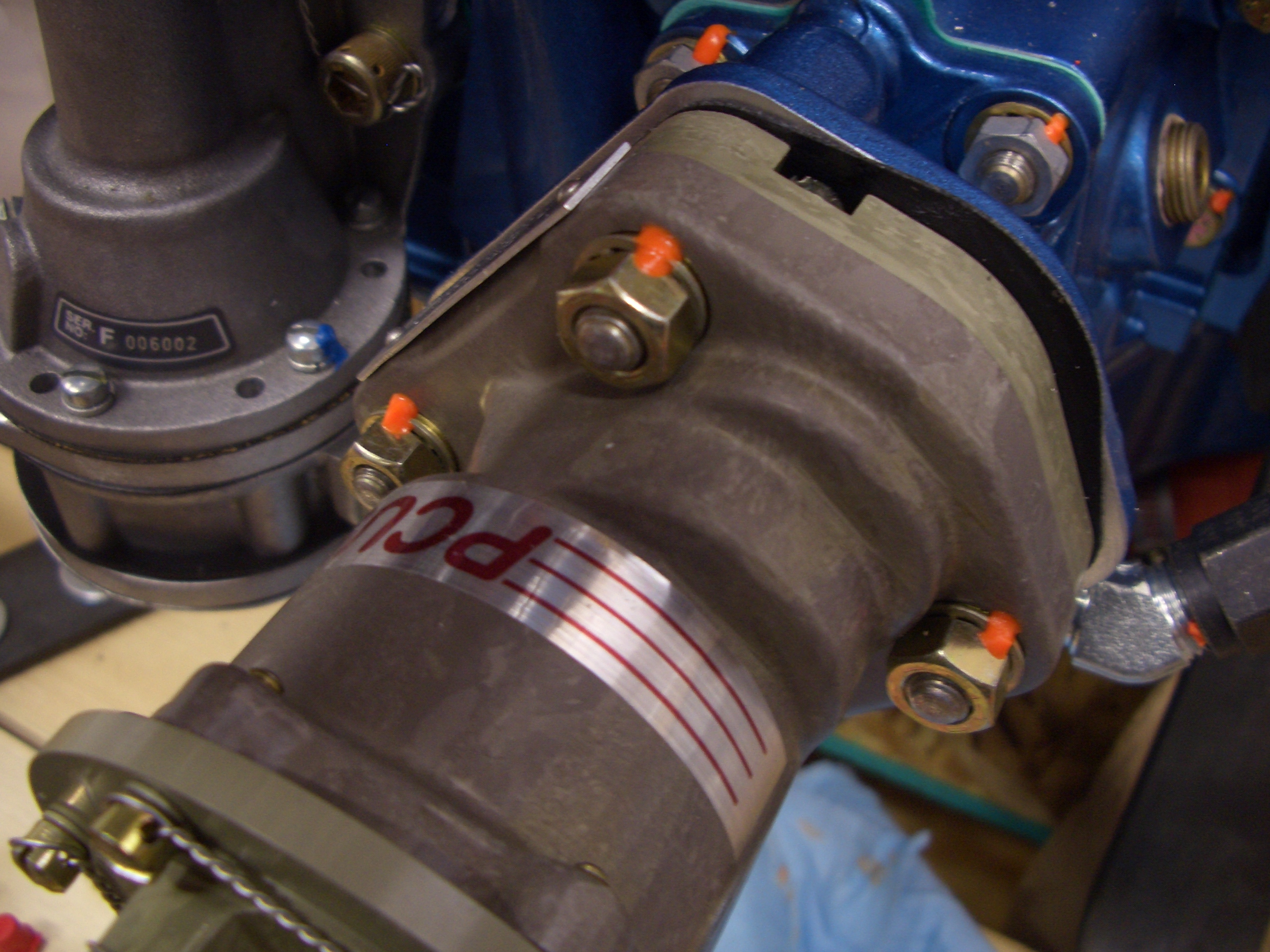
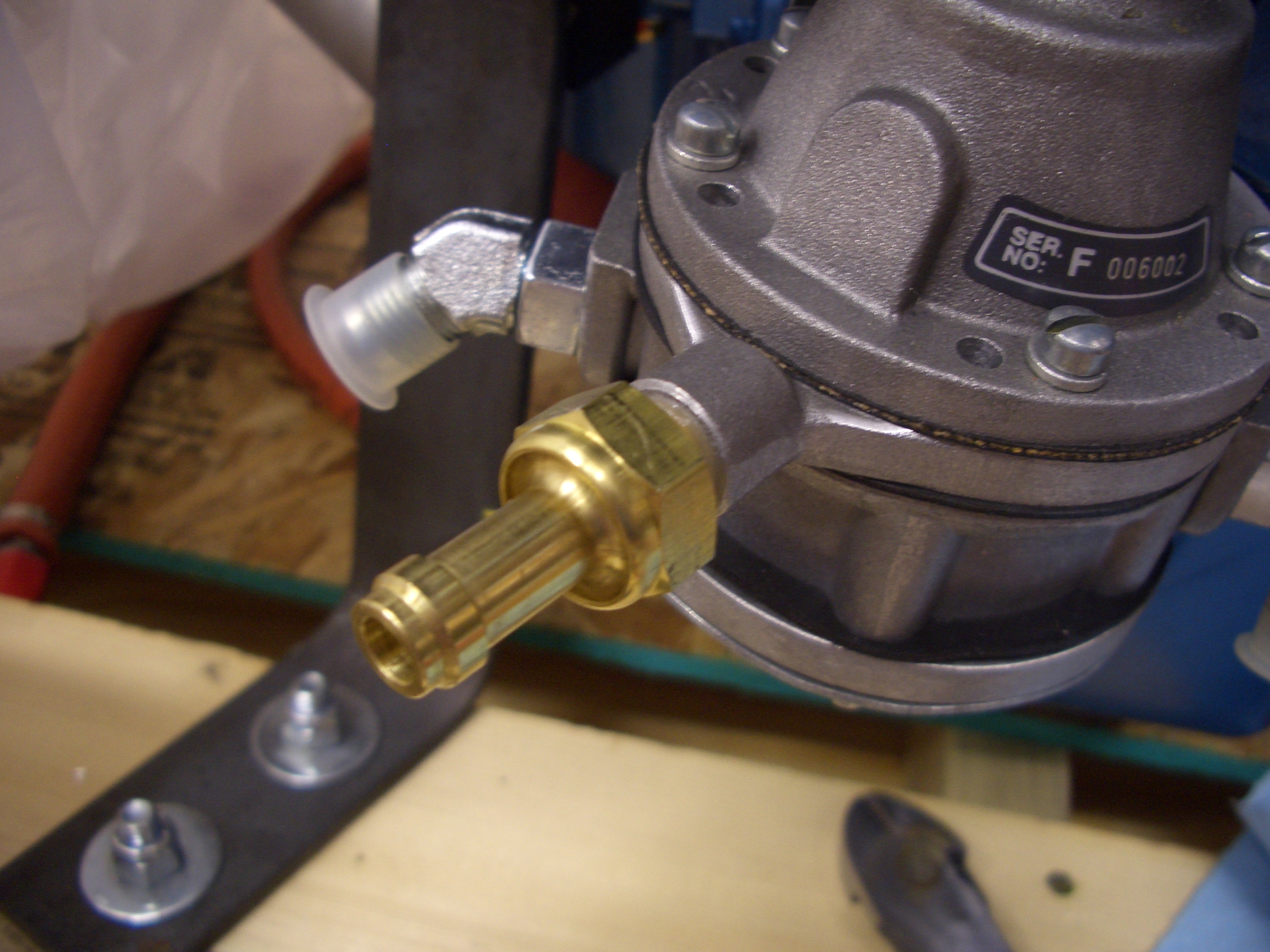
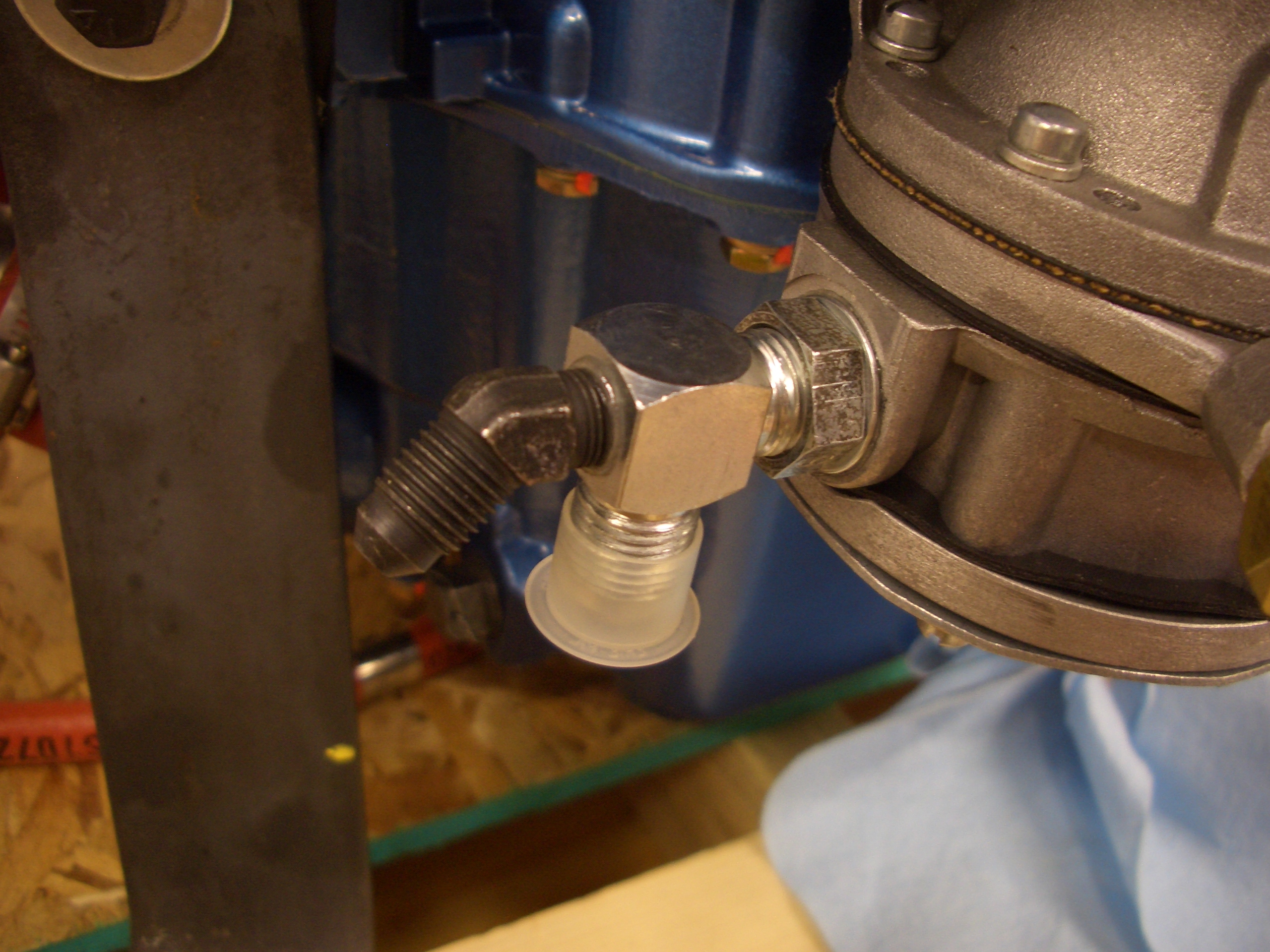
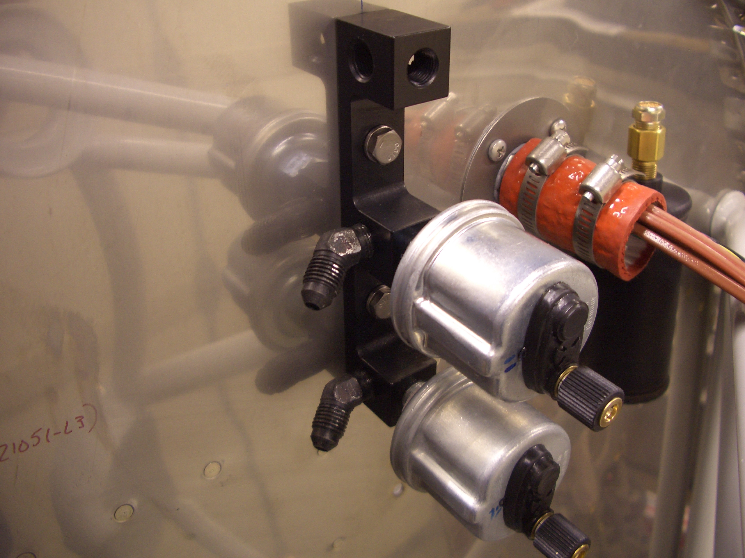
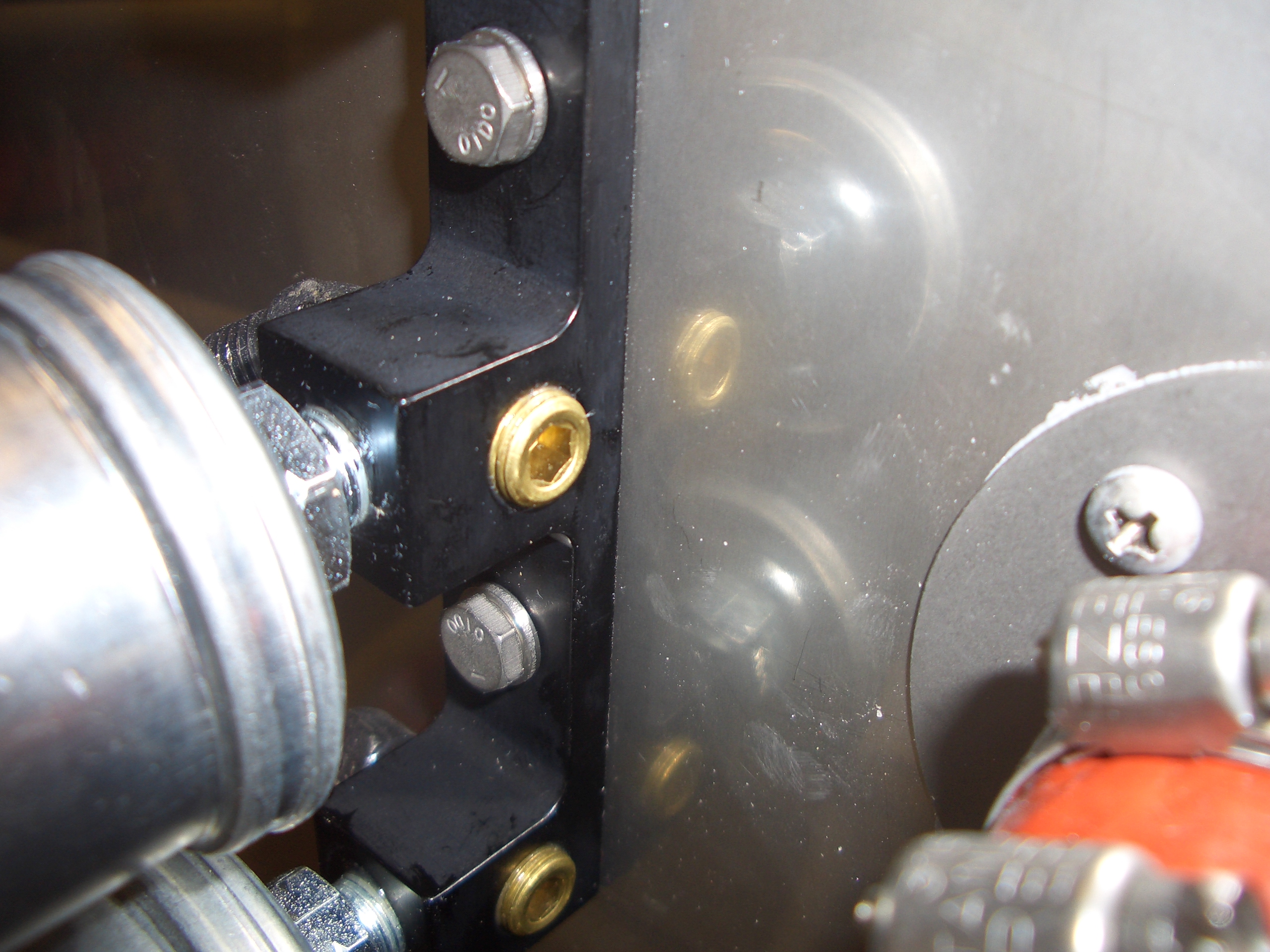
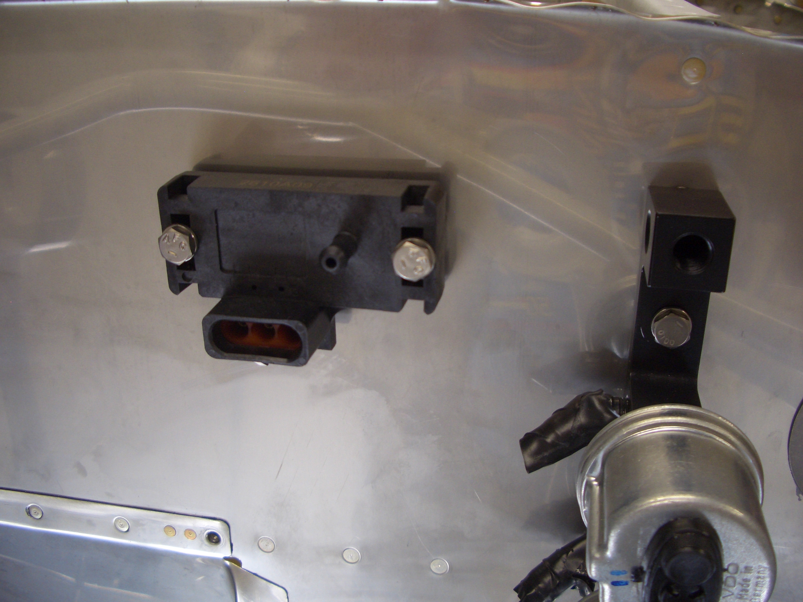
This is the mechanical fuel pump.  The fuel first passes through an electric fuel pump in the cabin.  This provides fuel delivery redundancy in case the mechanical pump fails.

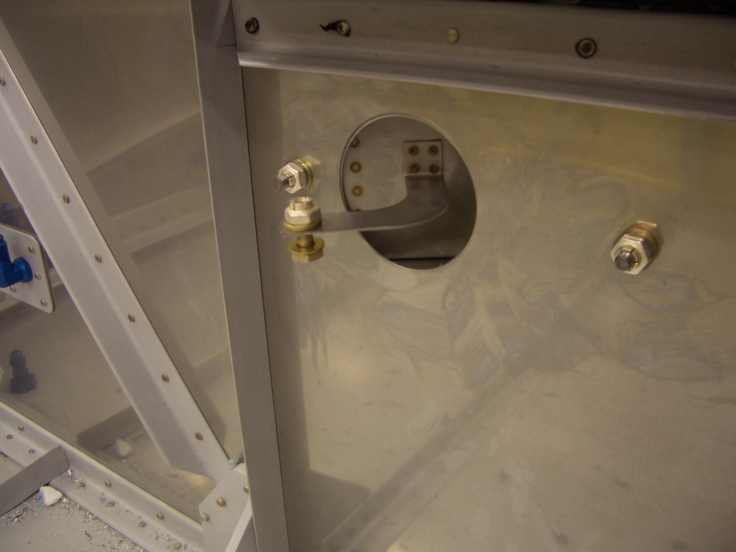
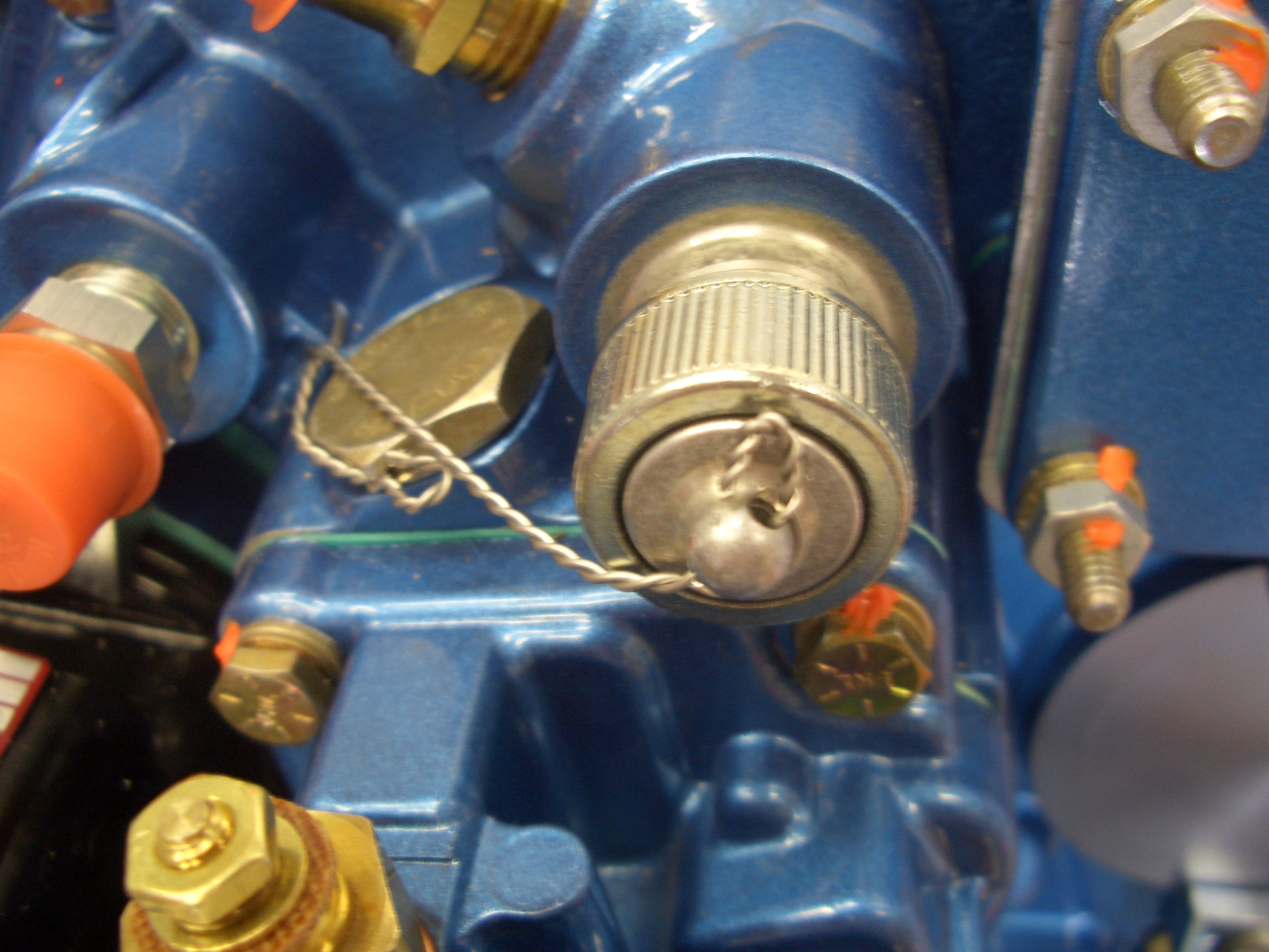
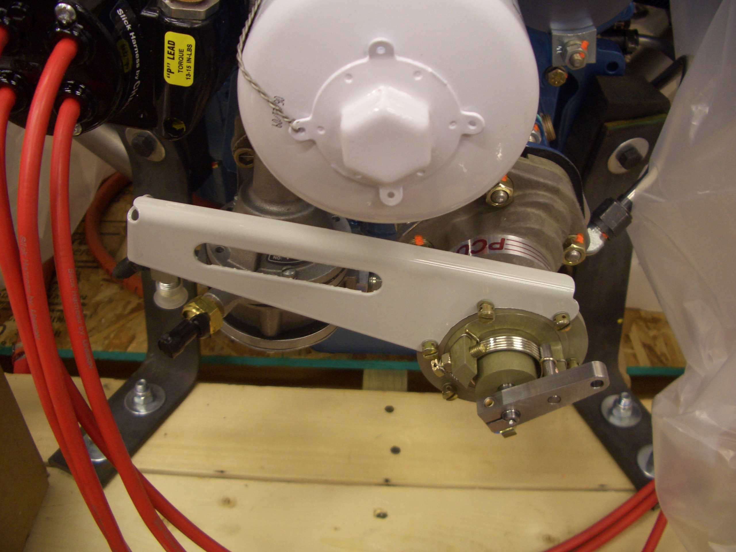
This is where the propeller governor will mount.  Fortunately, the studs are already installed, since I’ve heard these can be a pain to put in.

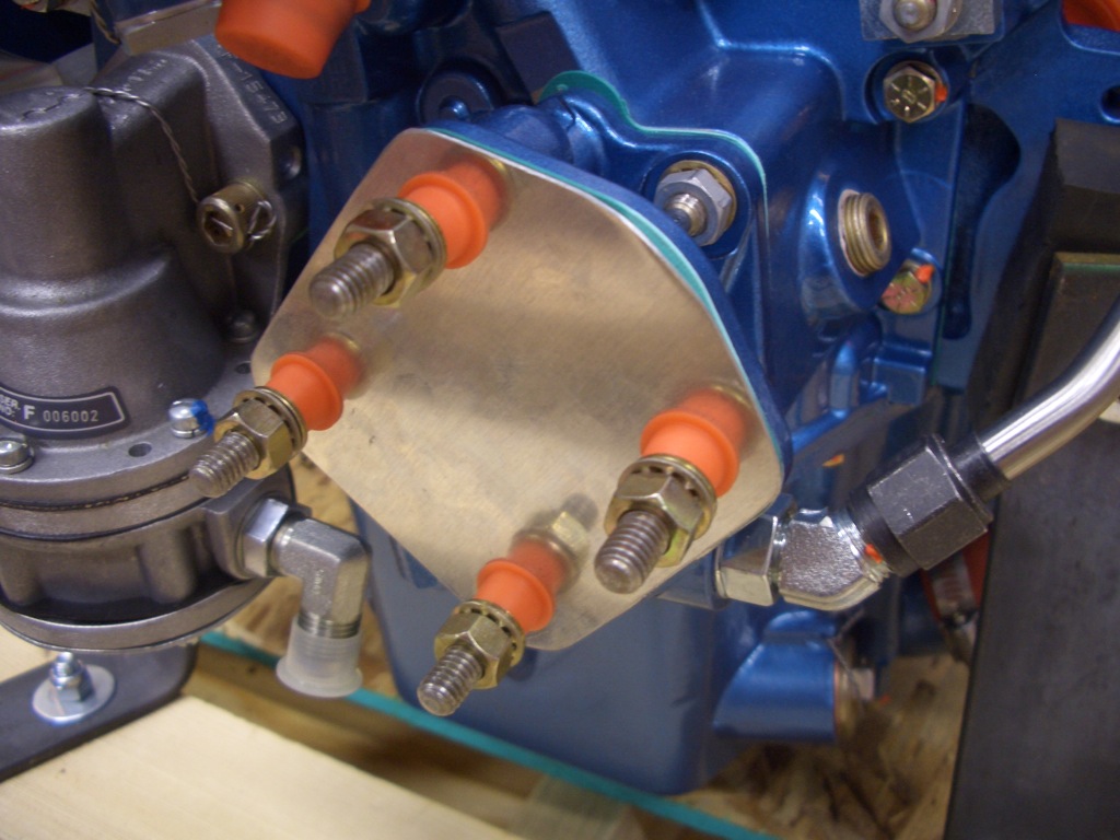
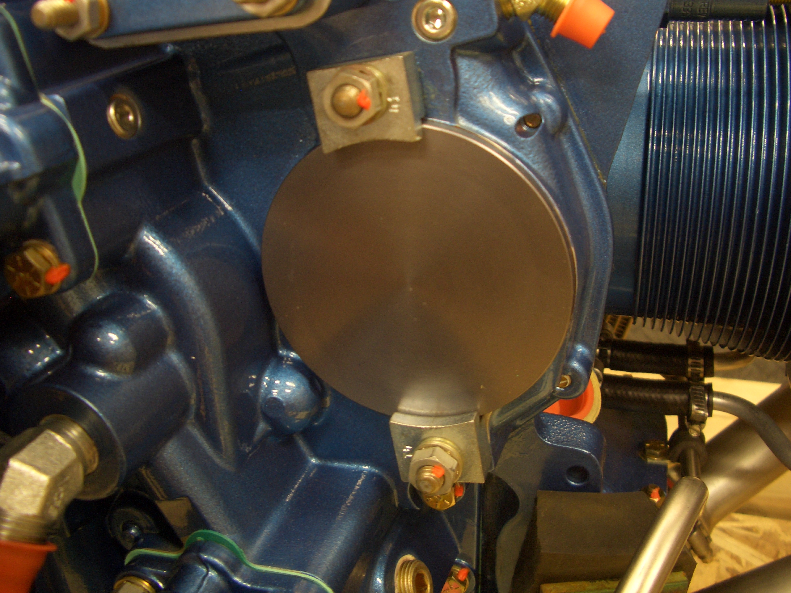
This is where the other magneto would mount if I were using dual magnetos.  Since I’m using an electronic ignition with a direct crank sensor, this is unused.  I may install a B&C Products SD-8 standby alternator here at some point.

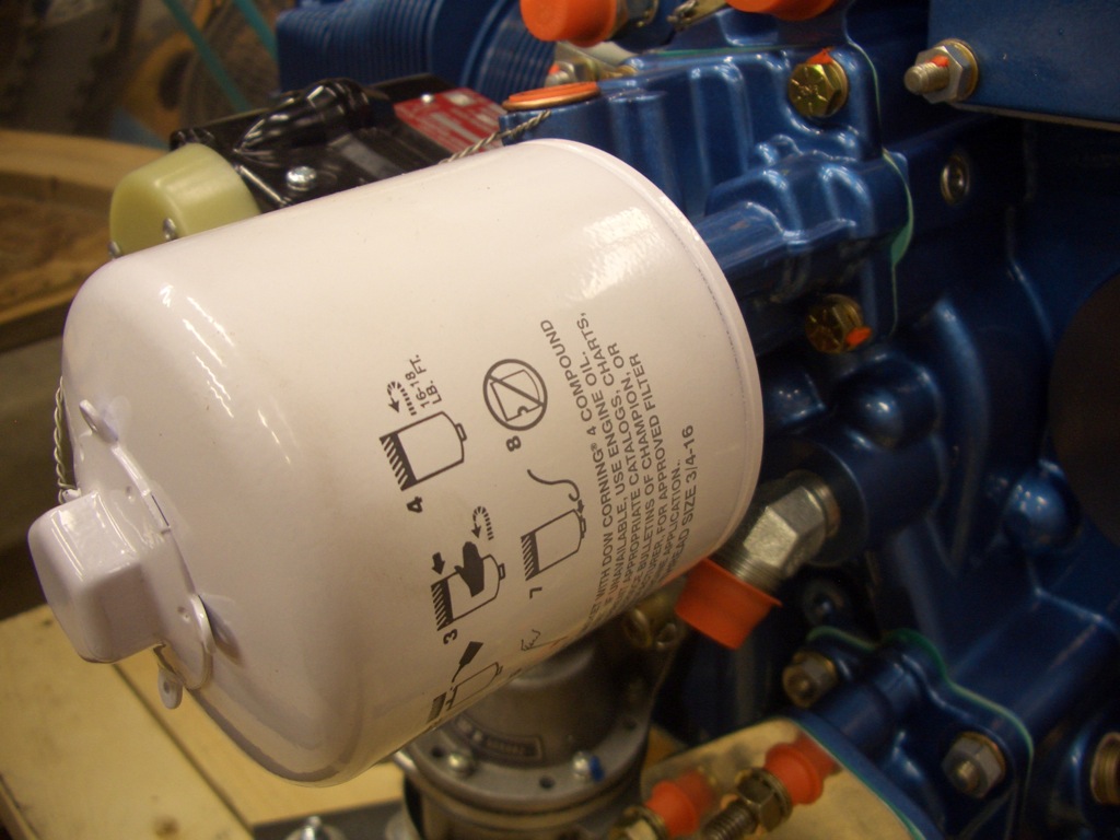
The oil filter mounts on the back of the engine.

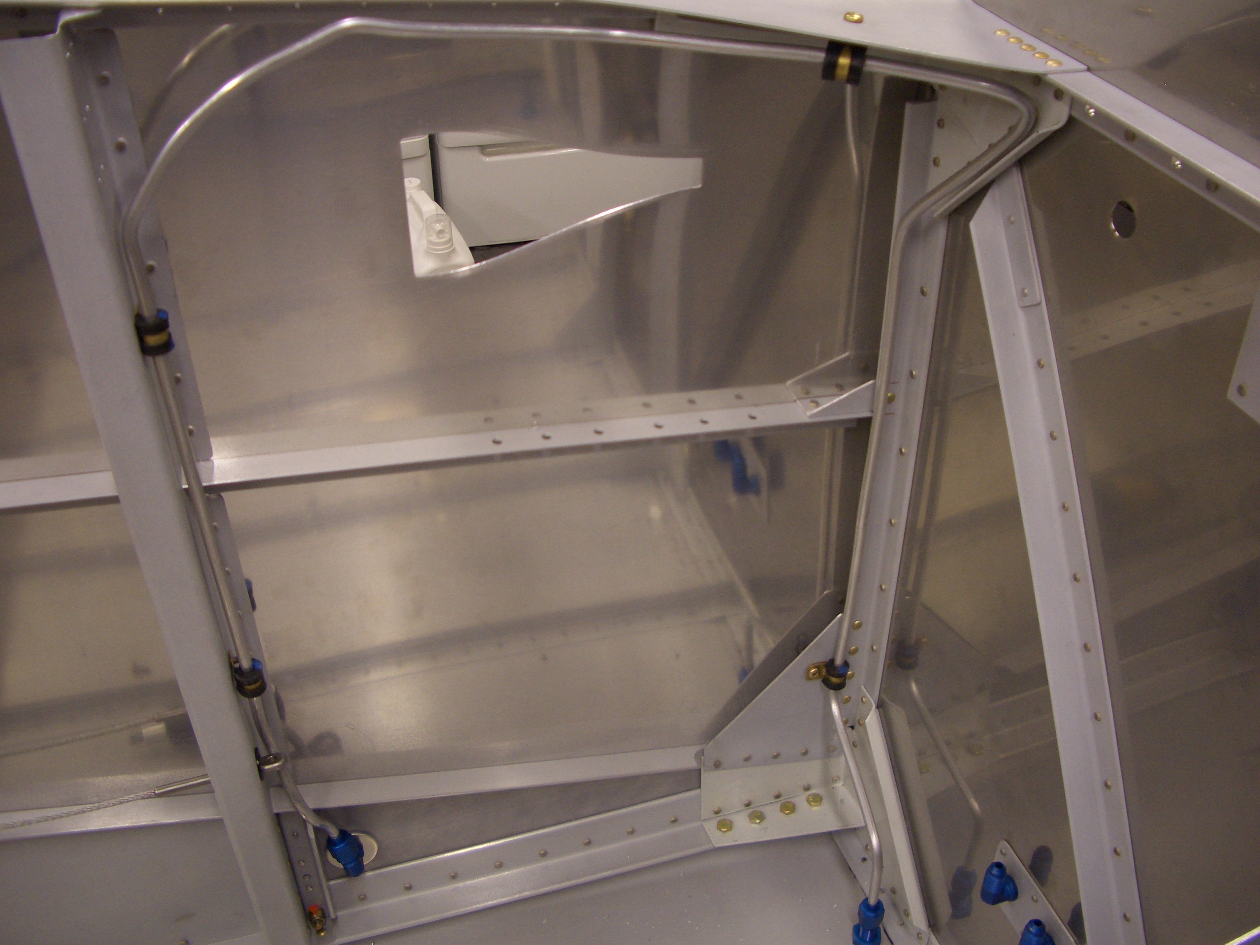
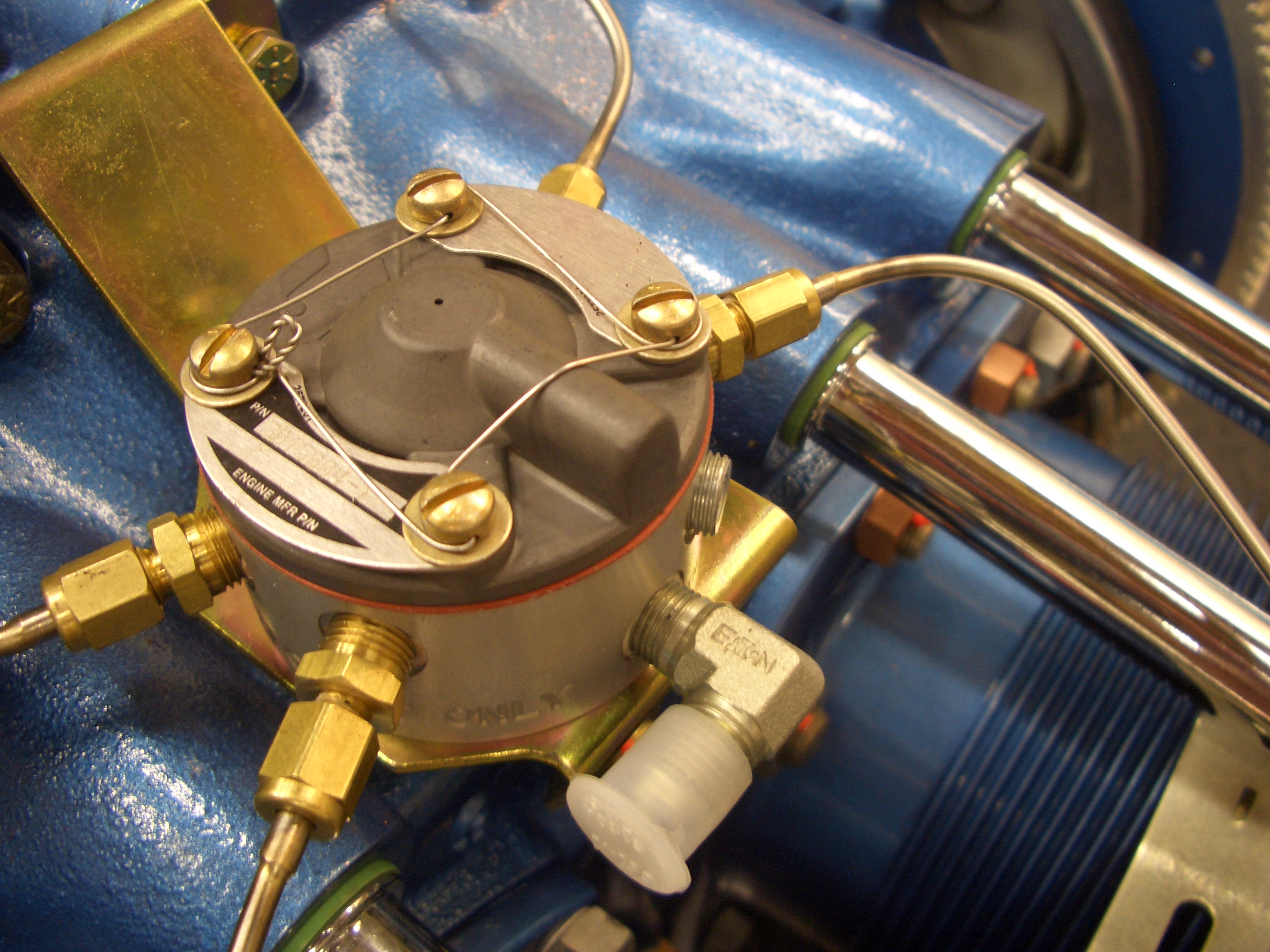
Here is the fuel distribution spider mounted to the top of the engine.  There are stainless steel lines from here to each of the cylinders.

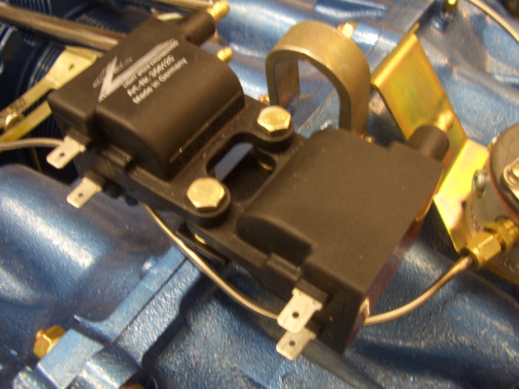
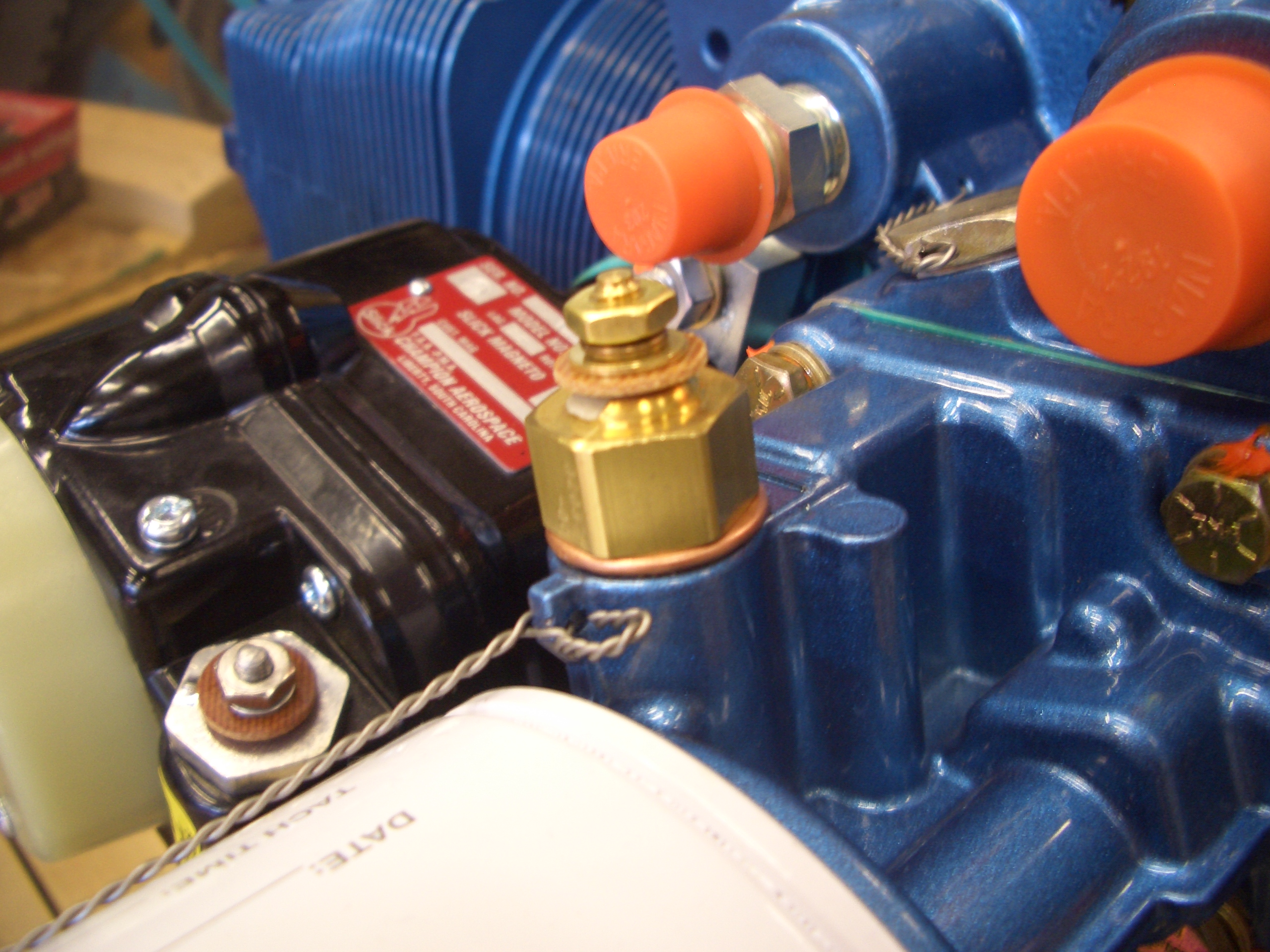
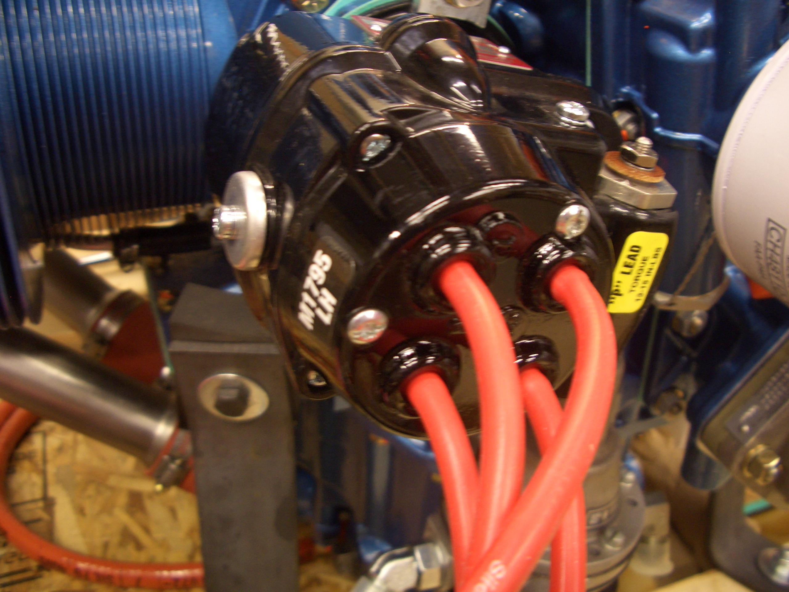
These are the ignition coils for the electronic ignition.  These will fire the top spark plugs while the magneto will fire the bottom plugs.

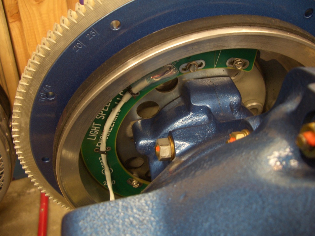
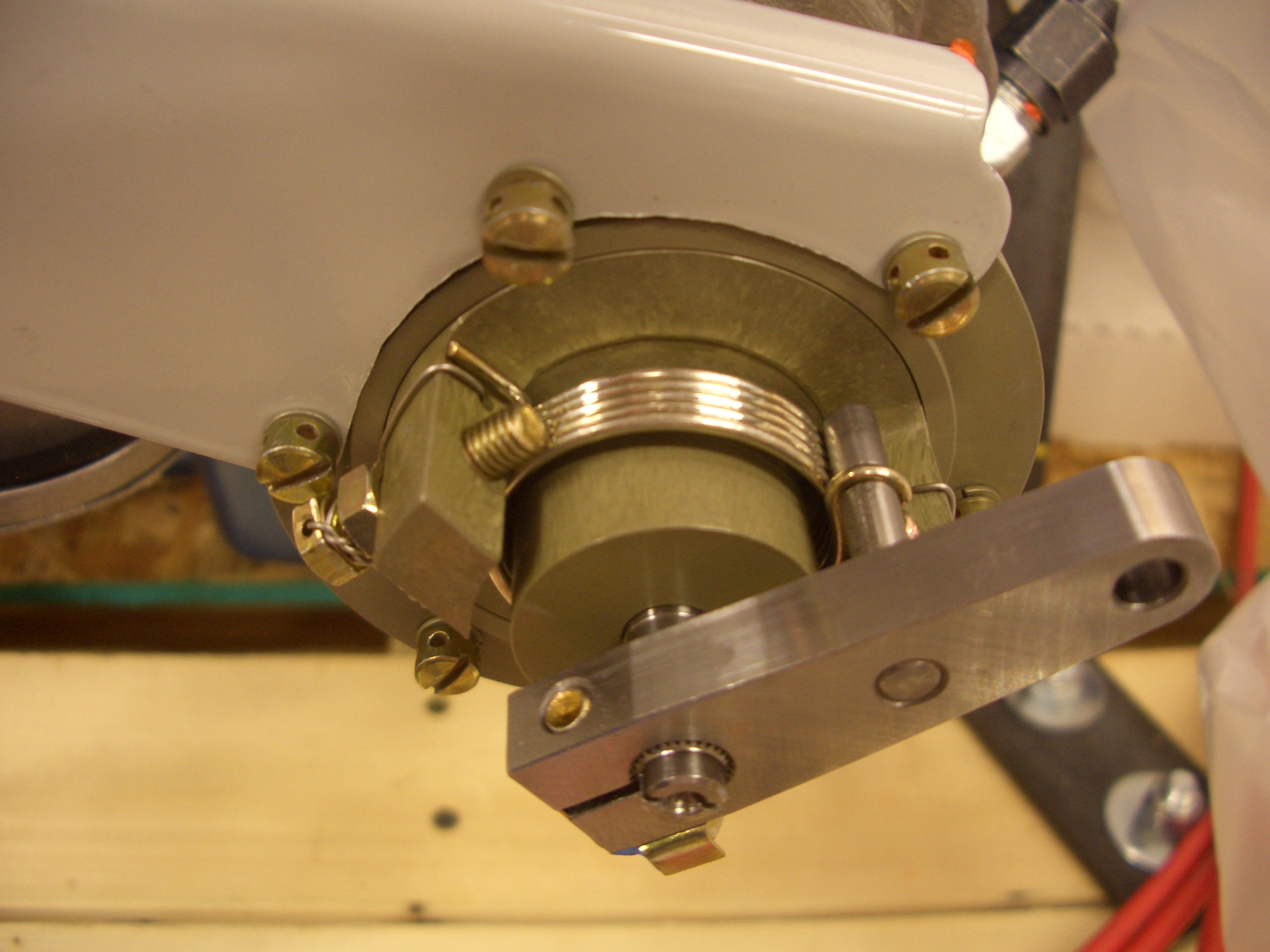
The electronic ignition detects the crank position using this crank sensor mounted inside the flywheel.  There are tiny magnets installed into the flywheel that pass by sensors on this circuit board.

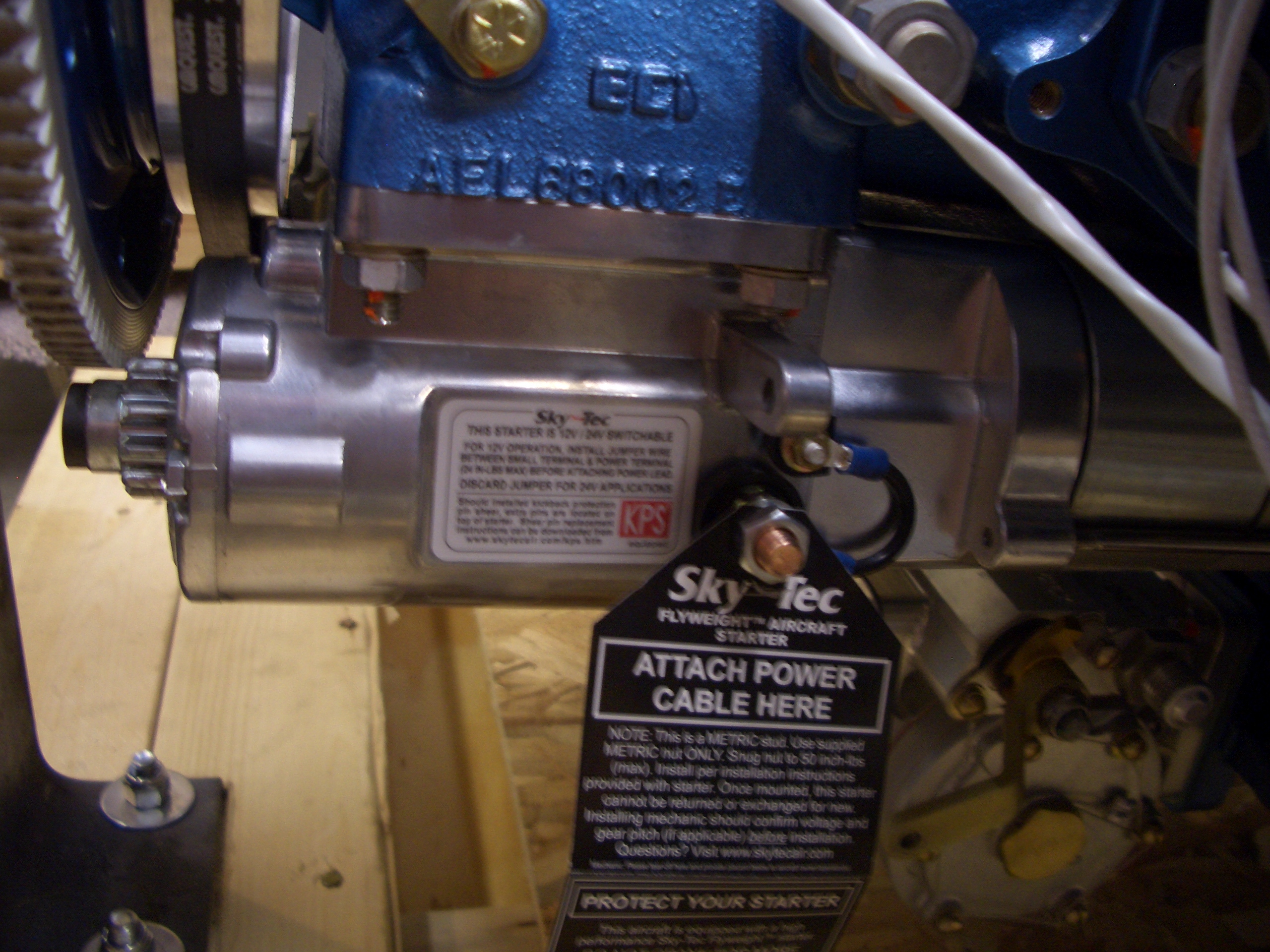
Aero Sport engines come with a Sky Tec Light Weight Inline starter.  Early versions of Sky Tec starters suffered from quality problems, but the company created new clean sheet designs that are very high quality.  I haven’t heard of anyone having issues with any of the newer model Sky Tec starters.

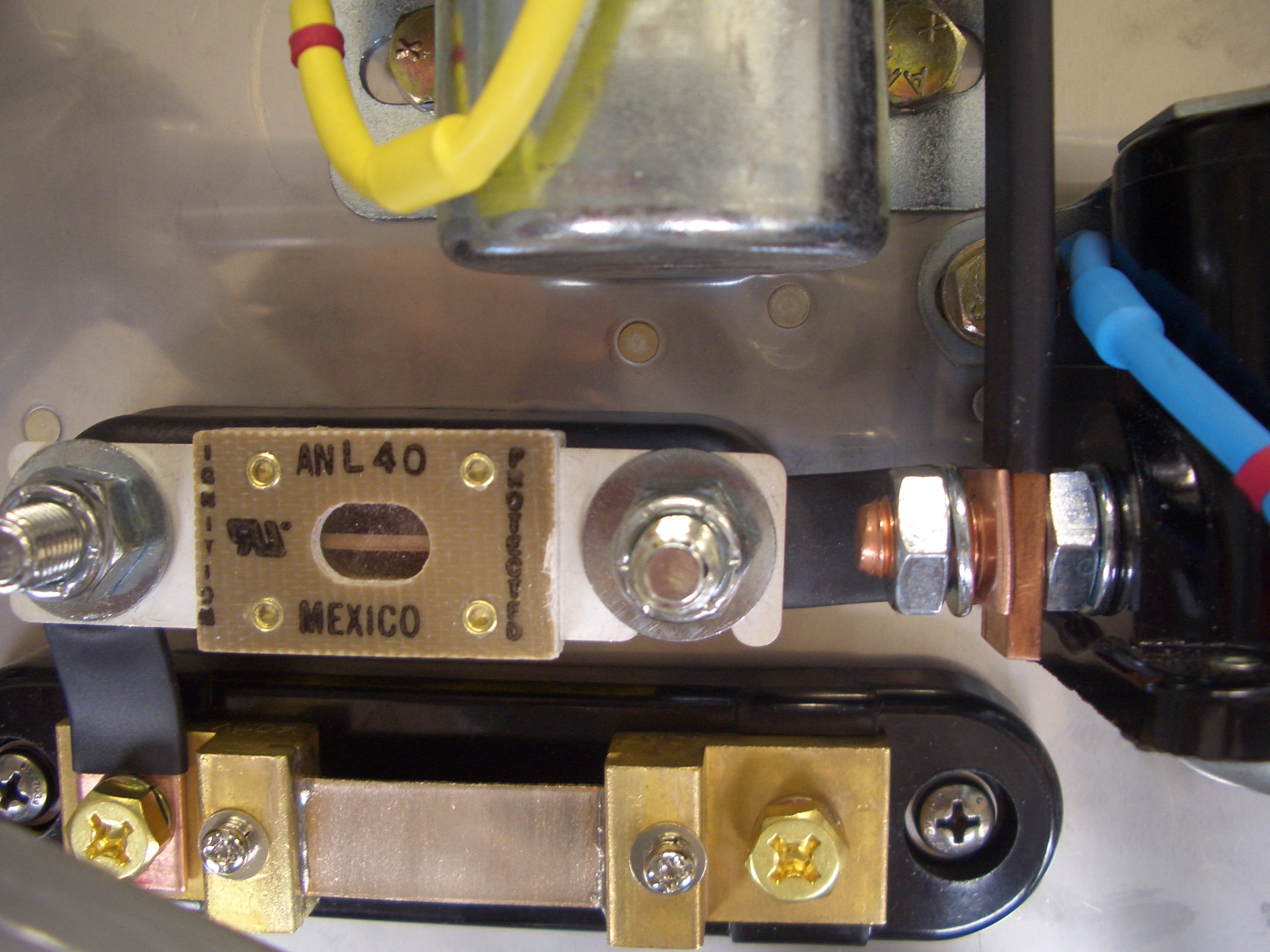
The B&C alternator requires an external voltage regulator.  This has a built-in crowbar over voltage protection feature to nearly instantly take the alternator off-line if it starts to go over voltage.

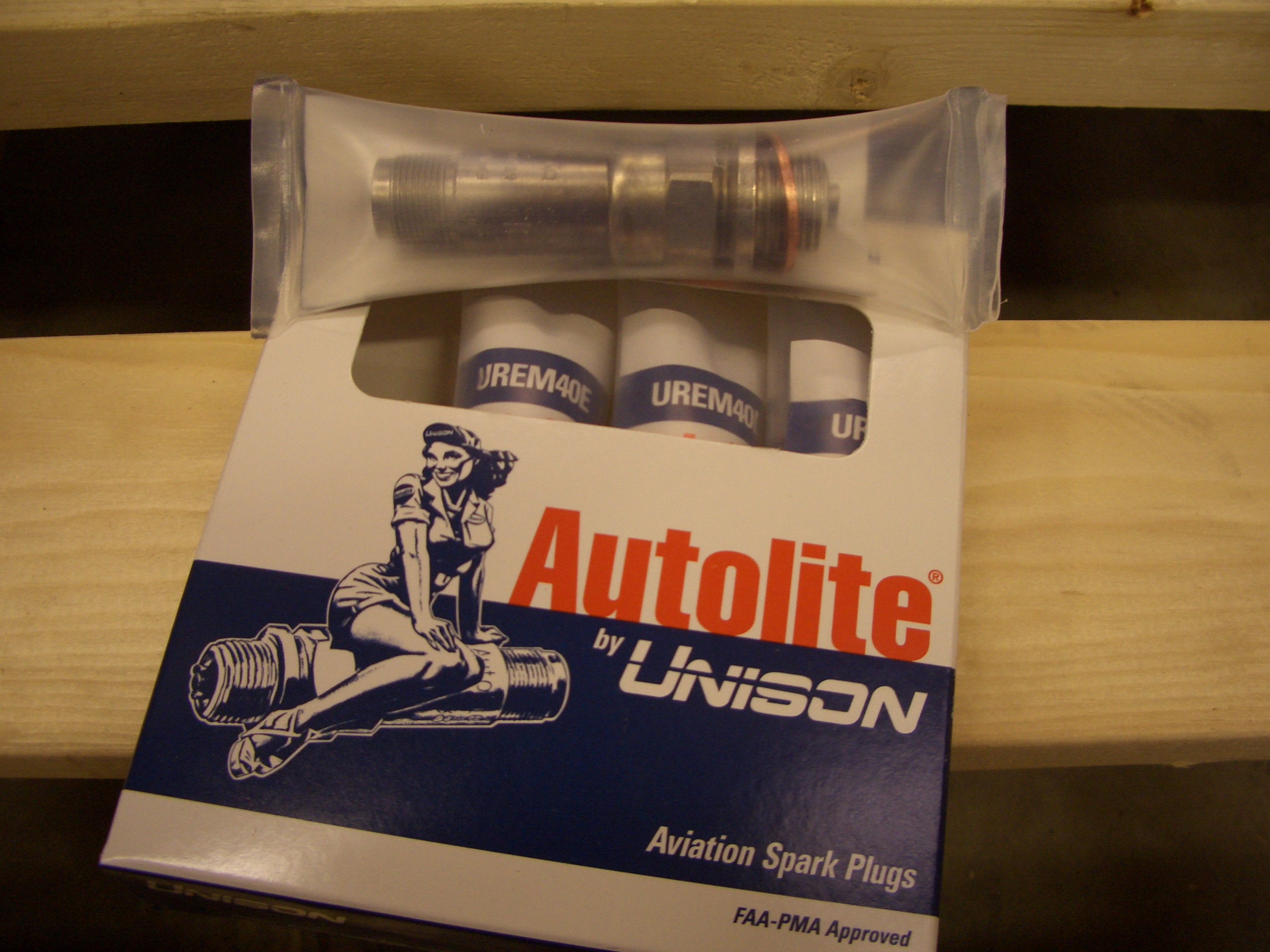
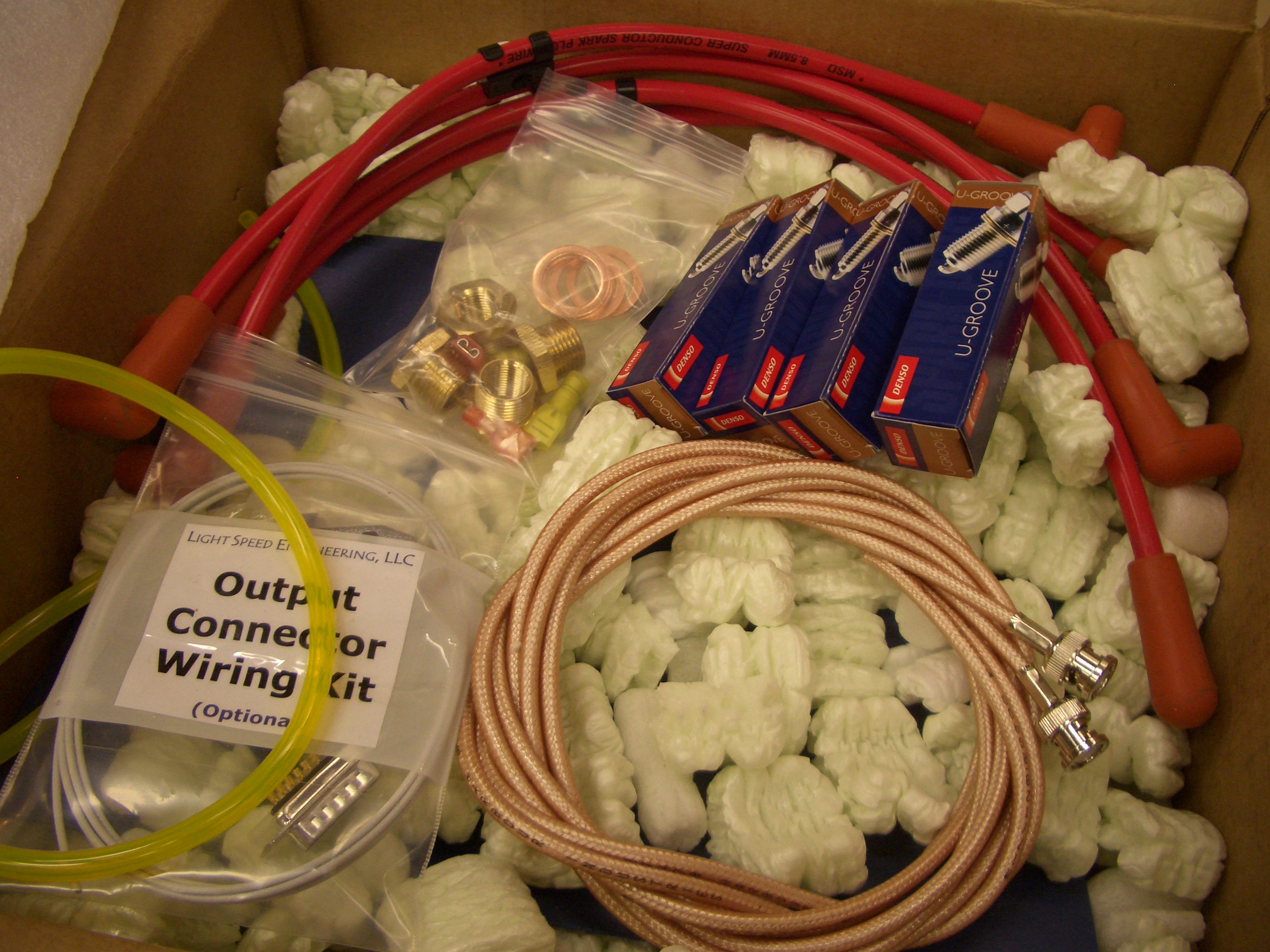
The crate also included new aviation spark plugs for the bottom set.

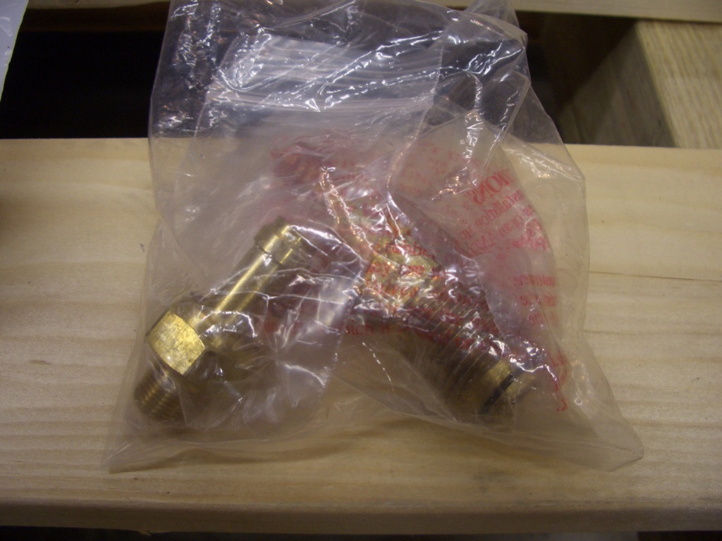
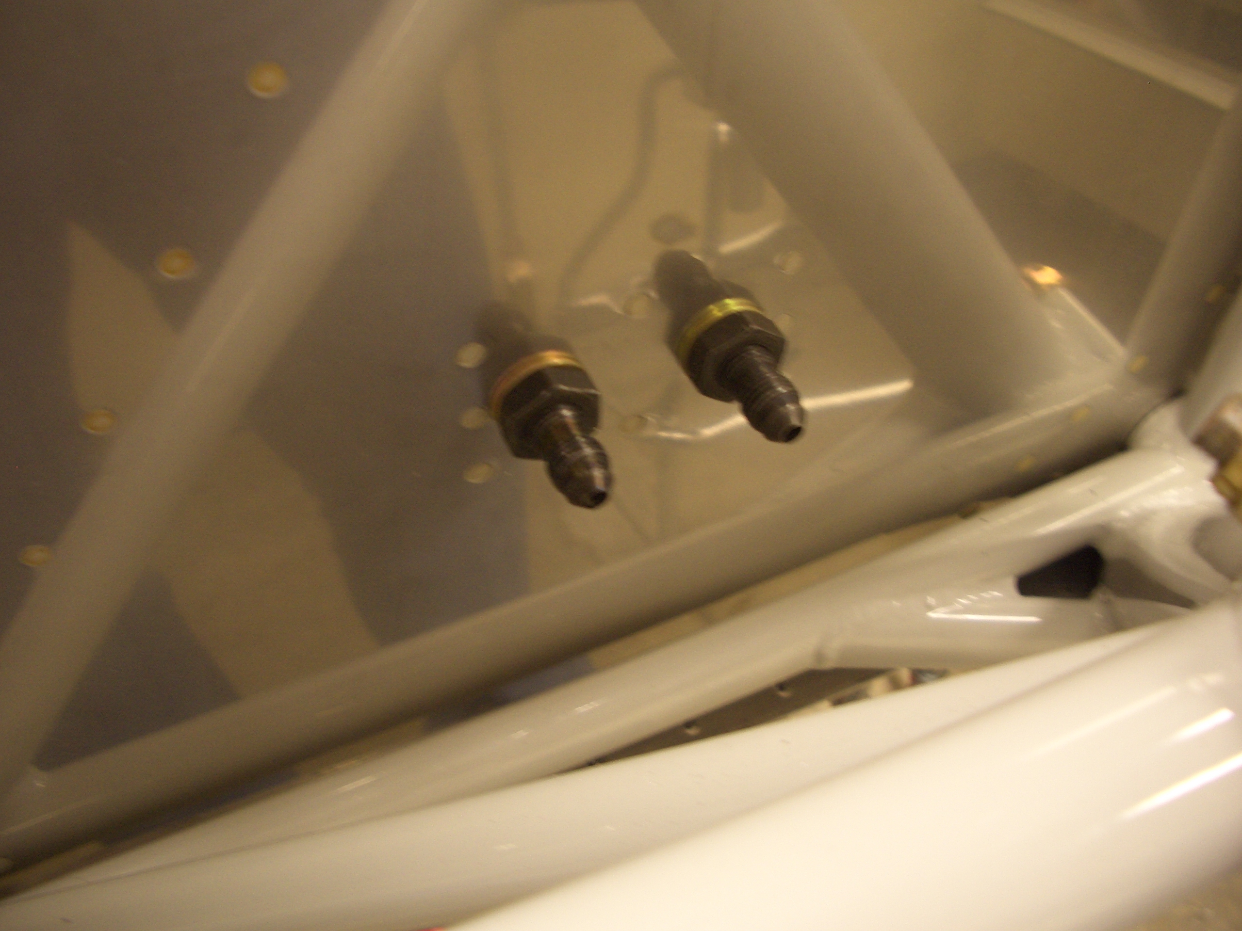
There are also some fittings that presumably need to be installed somewhere.

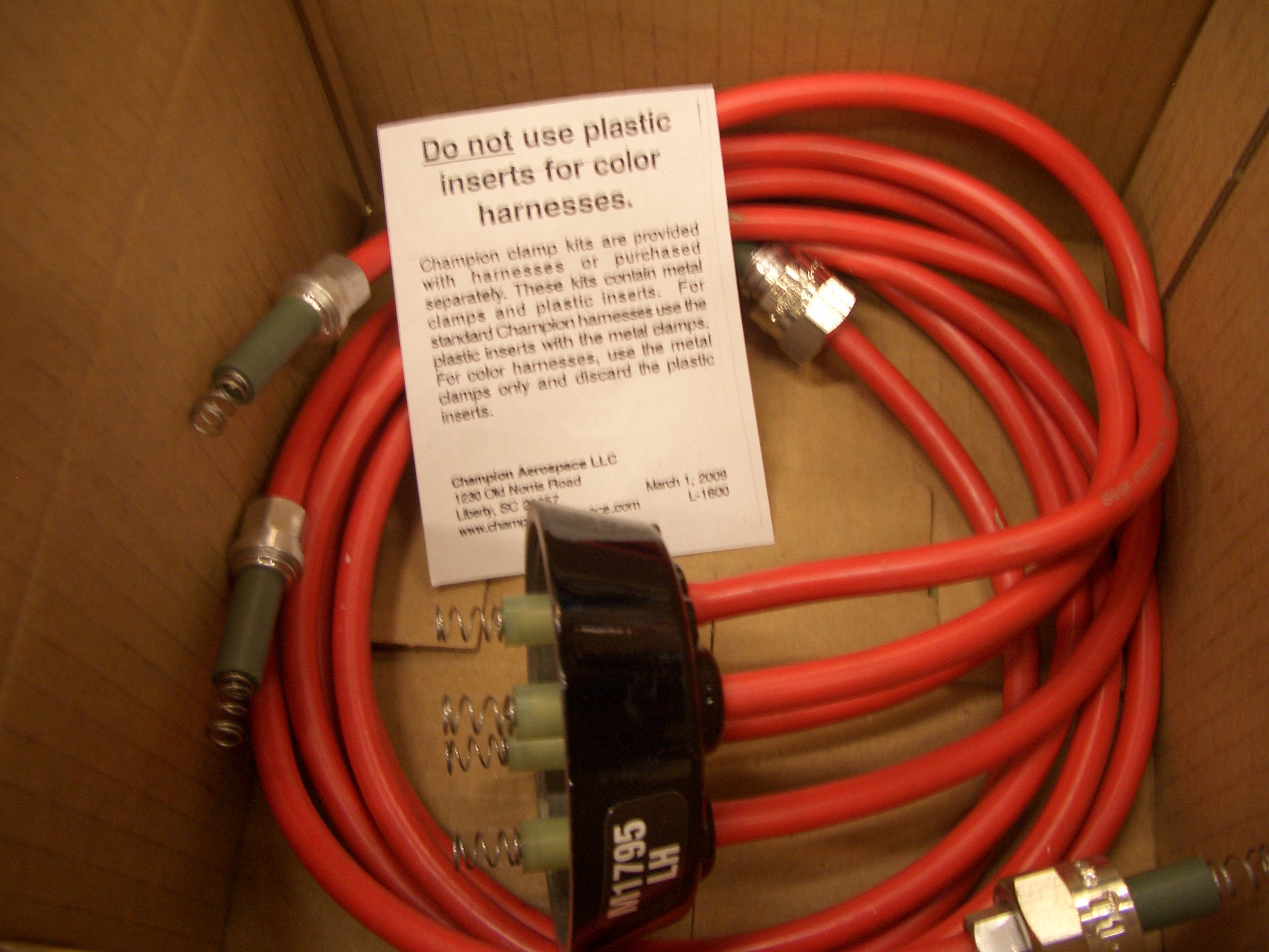
Here are the spark plug wires for the magneto.

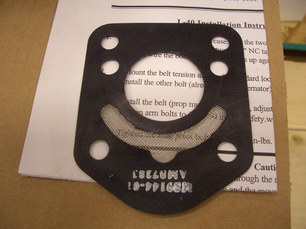
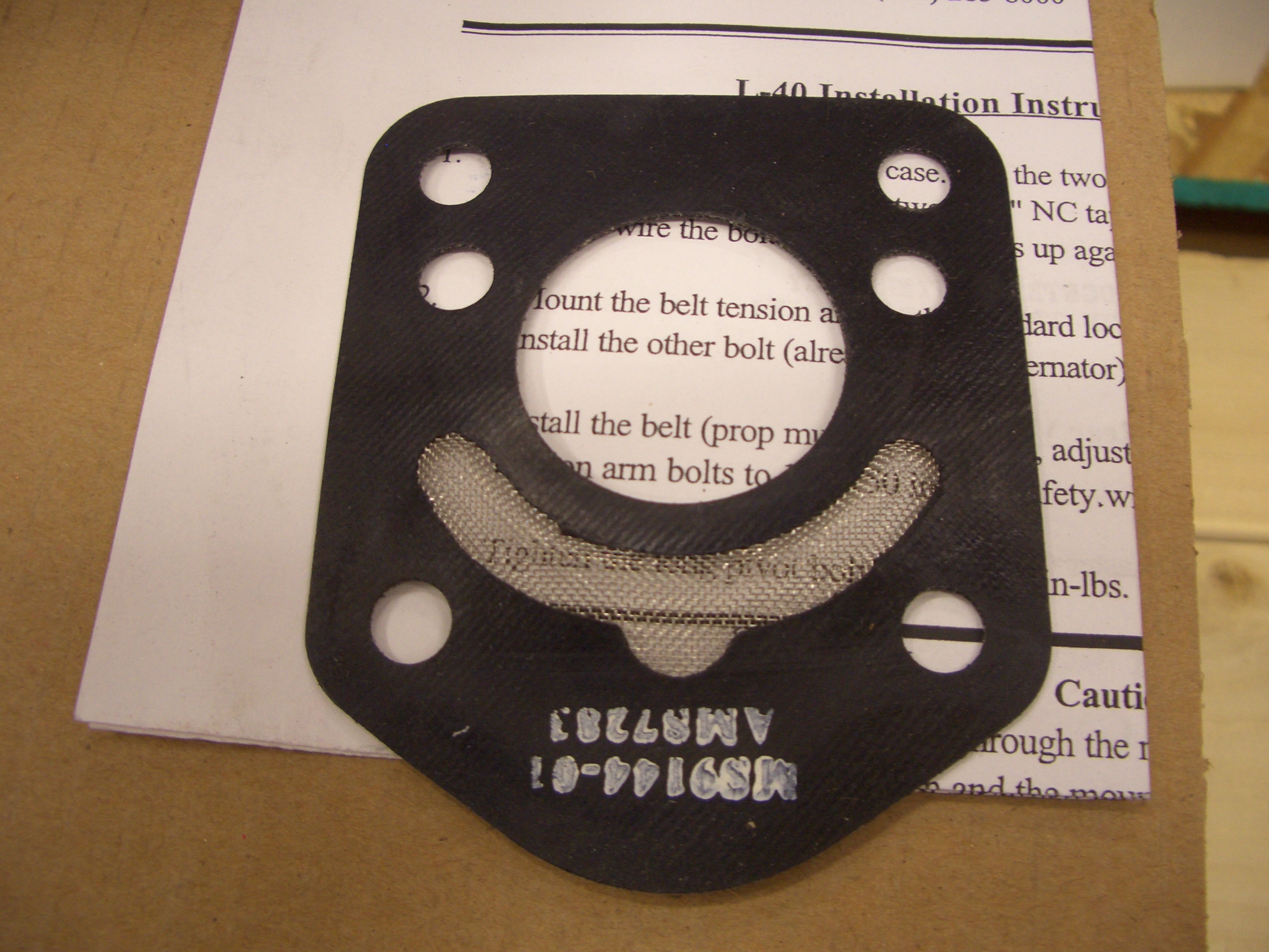
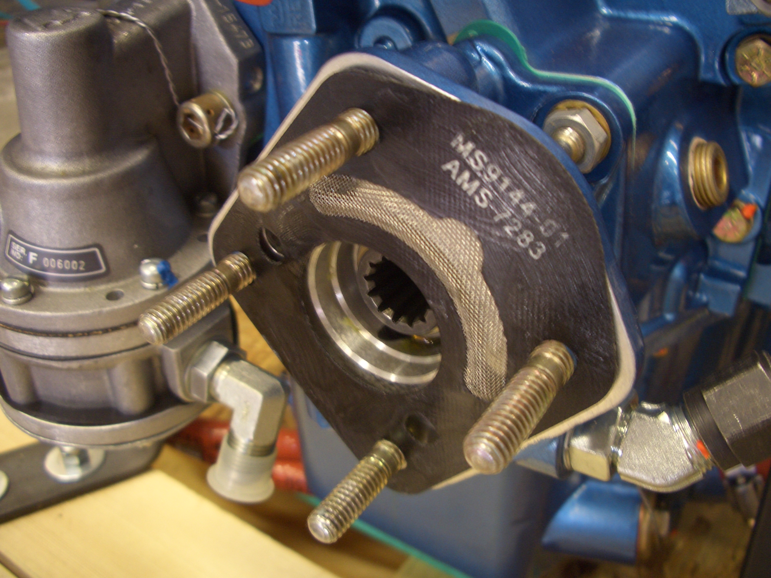
This is the propeller governor gasket with a stainless steel screen to keep debris out of the governor.

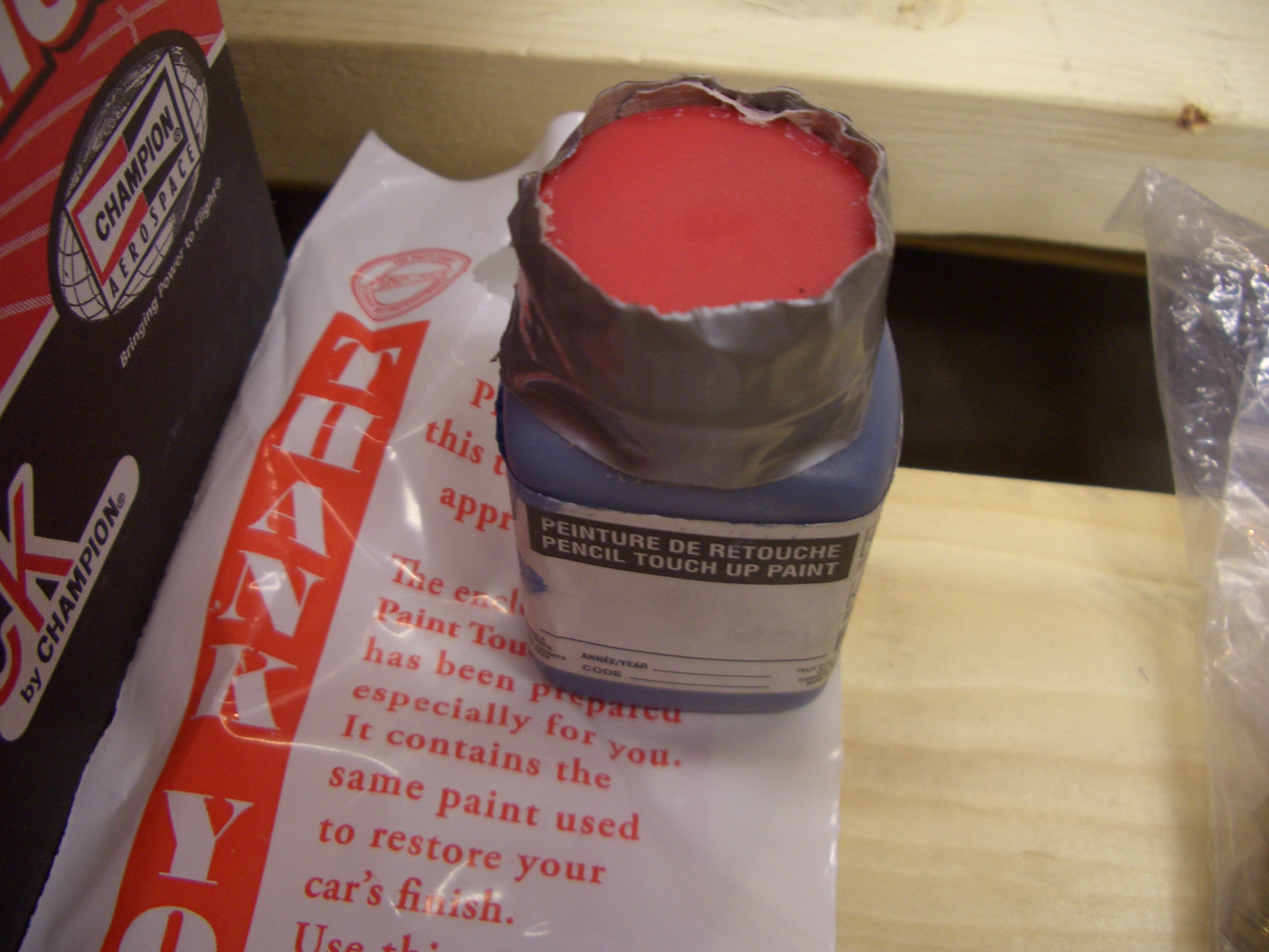
Aero Sport kindly included a small bottle of touch up paint for the inevitable scratches that I’ll get on the engine before it’s ready for flight.

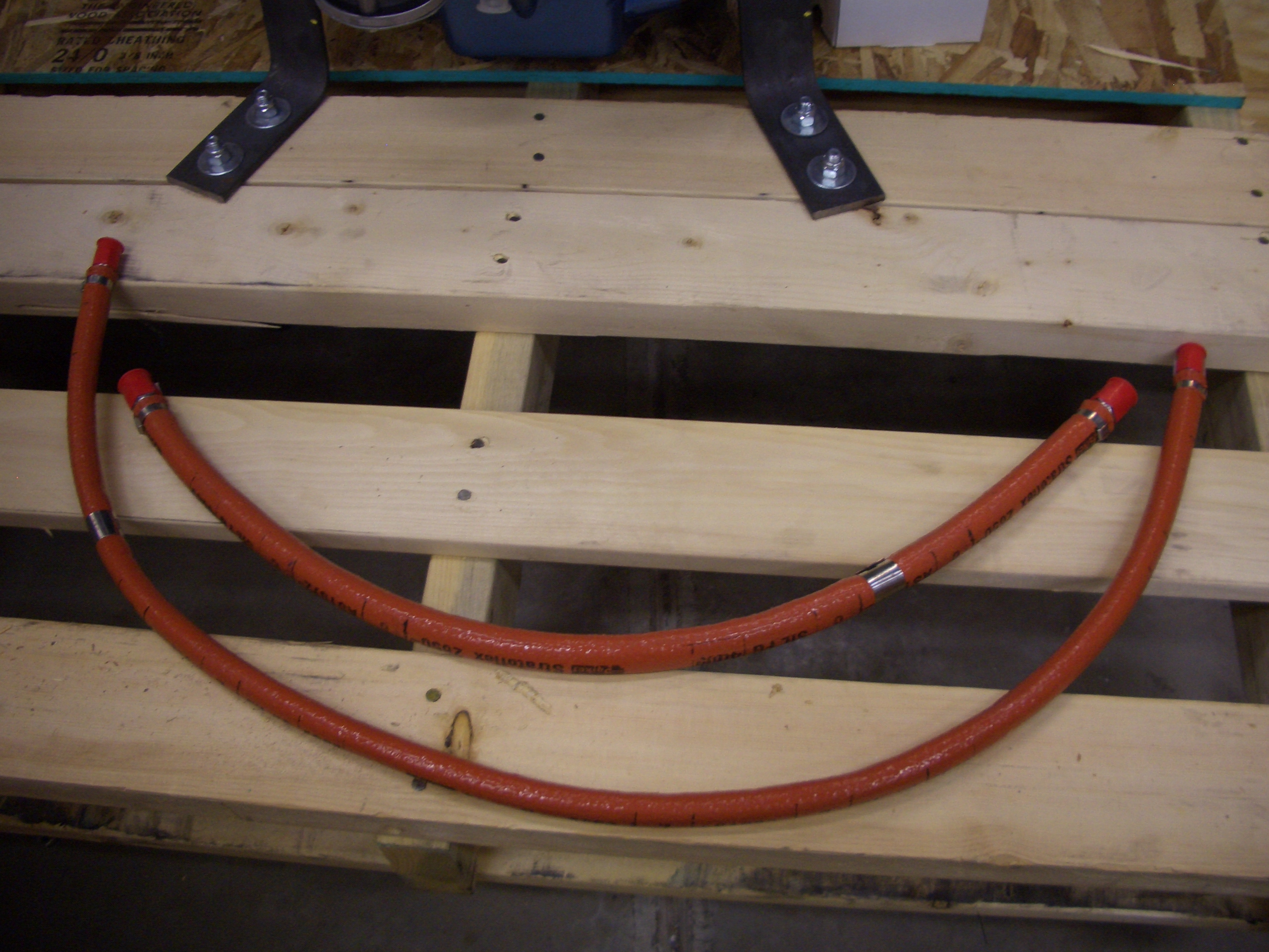
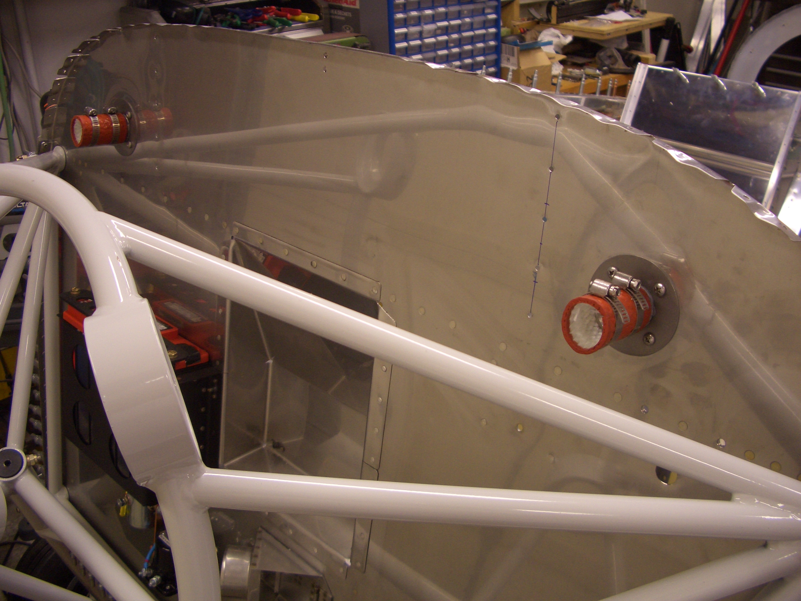
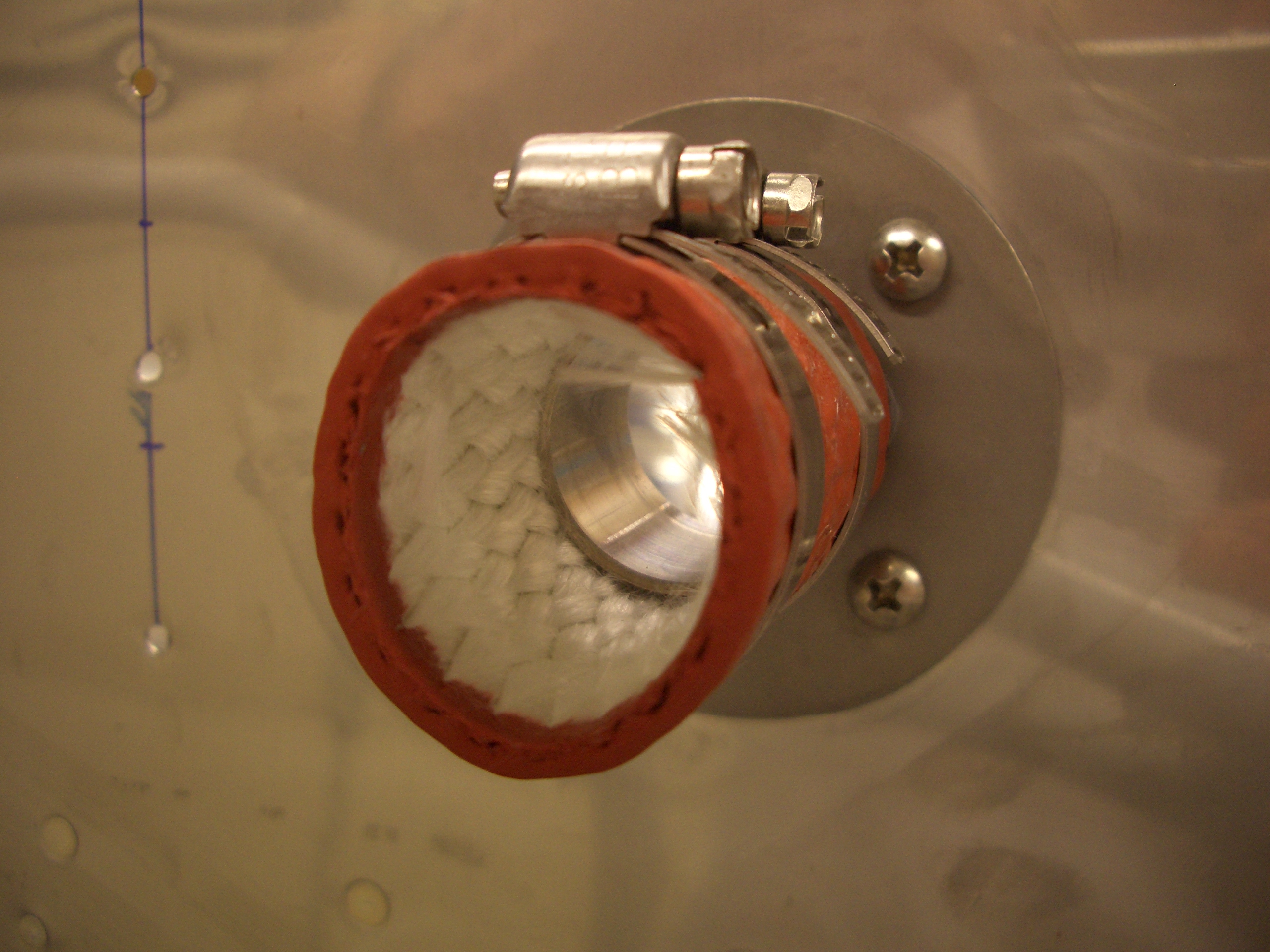
The crate also included a couple of firesleeved oil hoses.  I’ll need to figure out what these are for.

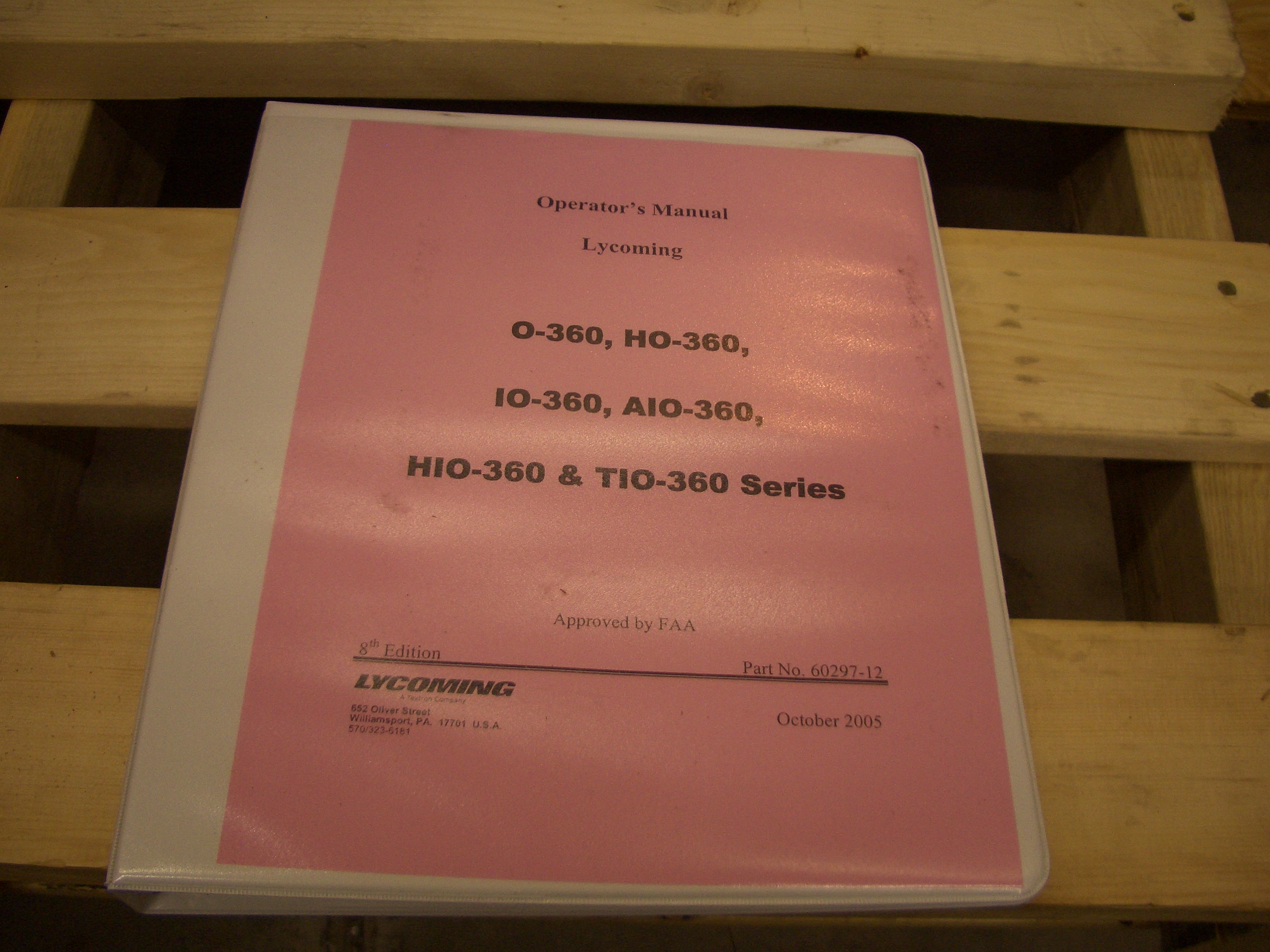
Aero Sport also included a Lycoming operator’s manual.

They also sent a couple of t-shirts which was super nice of them.

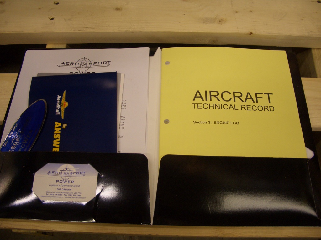
There is also a packet of info from Aero Sport that includes an engine log.

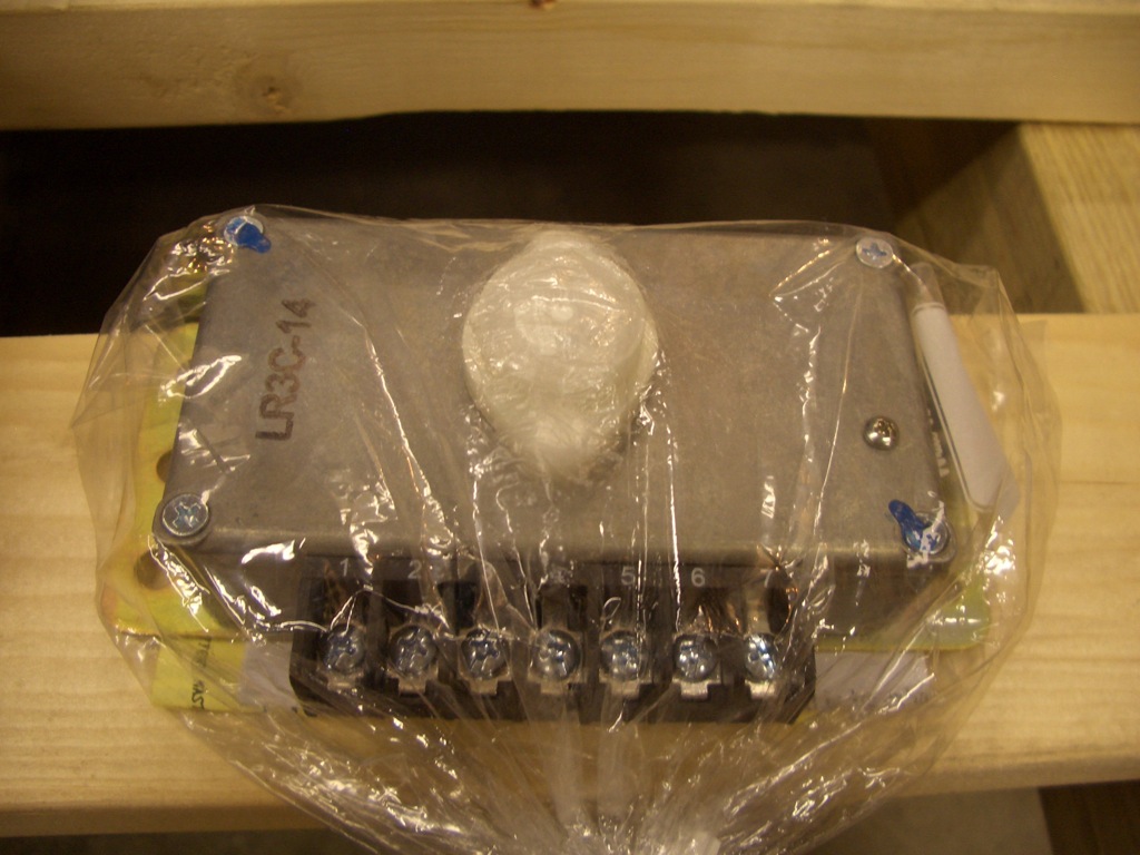
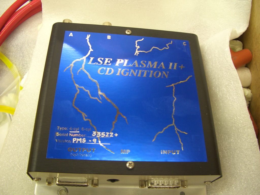
Here’s the brain box for the Lightspeed ignition.  This will mount behind the firewall to keep it away from the heat and from engine cleaners and water.

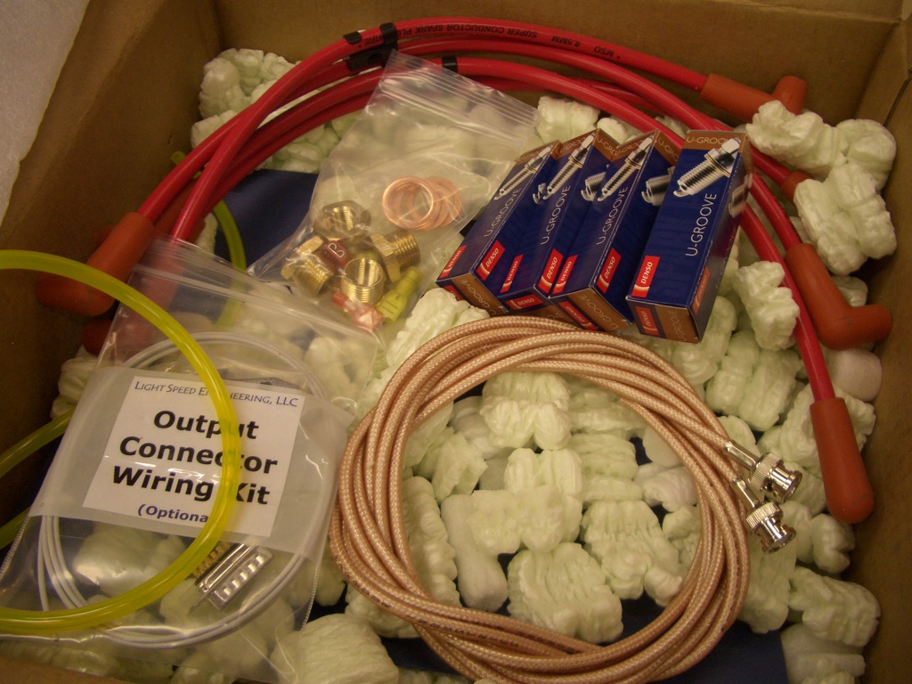
The box from Lightspeed also includes a set of automotive plugs, adaptors, spark plug wires, etc. for hooking up the electronic ignition.

Engine Accessories and Controls

I did some reading today in the manuals that came with the engine to determine where various sensors are installed.  This is the spot for the oil temperature sensor (which is included with the Dynon probe kit).  Fortunately, Aero Sport included the crush washer under the orange cap that was in this spot.  I haven’t torqued this down yet because I’ve been unable to find a torque value for this fitting.

I also took off the cover plate for the prop governor mounting pad.  I put a thin coat of grease on the gasket and installed it on the pad.

Finally, I installed the PCU 5000 X governor on the pad.  I haven’t torqued these either since the cable mounting bracket will have to attach using a couple of these bolts.  It looks like there will barely be enough threads showing without that, so I’ll have to ask about whether I can just back these studs out a couple of turns or not.

I also took the cover off of the back of the magneto and installed the wire harness.  These use T20 screws, and I wouldn’t have had enough room to get my torx driver between here and the firewall if I had waited until the engine was hung.

I also shaved a few thousandths off a couple of AN960-10 washers to allow this center control piece to pivot freely.  The bearings used in the control mounts are very sensitive to side loading.  Even 5-10 thousandths of an inch difference between the mount spacing and the spacing in the control piece was enough to make moving this have some noticeable friction.  It’s completely frictionless now.

Work on Seats, Engine Accessories

I drilled the upper seat back adjustment to the right seat back.

Here is the seat installed temporarily.  I still need to drill out everything to #30, but all of the fabrication is done.

Here is the upper seat back adjustment showing how the flange fits into the notches on the cross member.  Afterward, I knocked out all of the left seat except for the upper adjustment mechanism.

I found out that the new prop governor cable mounting bracket doesn’t attach to these mounting bolts, so I torqued these down and lacquer sealed them.

I also swapped the oil pressure fitting and the plug so that I have more clearance from the engine mount.  This required removing the upper hold down clip from the right mag cover plate so that I could get a wrench on this fitting.

I also installed the fuel overflow fitting.  A rubber tube will be installed here to route any fuel overflow away from the hot exhaust.

Update: This is the sniffle valve and shouldn’t be installed here.  I searched all over the engine and couldn’t find any other fittings that this could screw in to, but the engine was mounted on the palette at the time and I couldn’t see where this should actually mount.  See this entry for where this should actually be mounted.

Engine Fittings, Firewall Pass-Throughs

My order from Avery Tools showed up today. One of the items was a cover for the tach port. This is used for a tach cable if you have a mechanical tachometer. The Dynon will get its RPM information from the Light Speed Engineering electronic ignition box. I safety wired this, but it really can’t prevent this from unscrewing since the center part of the cap is separate from the outer part. At least it would prevent it from falling off though.

I don’t know if the high pressure fuel screen will need to be cleaned frequently or not. If so, I might want to find another place to safety wire this to so that it doesn’t run across the fitting.

My daughter was a big help with this. She kept pointing to parts on the engine and asking “what’s that?”

I also removed the regular 45º fuel outlet fitting and installed a 90º tee fitting. The bottom silver part of the fitting will connect to the fuel injection system. The black fitting has a restrictor inside and will tie into the fuel pressure transducer.

I also got an order from Van’s that included the prop governor cable bracket. After some grinding of the inner radius and elongating a couple of the holes slightly, it fits quite well. I had to cut off the safety wire for all six screw holding this ring on so that I could rotate the head and control arm. I can’t determine the final position of the control head until my prop cable shows up next week.

Here’s the entire bracket. The cable housing attaches to a hole on the left side and the cable passes through the slot in the bracket.

I also got an order from Aircraft Spruce that included some steel fittings to replace the aluminum ones I had installed for the brake lines. I’m trying to use steel fittings for all firewall penetrations if possible.

My order from Avery Tools included a couple of firewall pass-throughs from SafeAir1. These have a stainless steel tube with a spun flange so there are no sharp edges. I installed them with some 2000º fireproof sealant and then installed the outer fire sleeve and clamps.

Here you can see through the pass-through. These each provide a 1″ opening for all of the wires that need to penetrate the firewall. I’ll use the one on the right side for all of the large power wires and the one of the left for all of the engine sensors. After the wires are installed, they’re wrapped tight with another piece of fire sleeving and some silicone tape and then pushed into the tube. The outer piece of fire sleeve is then slipped in place and the clamps are tightened.

Seats, Oil Temperature Sensor

I finished fabricating the seat backs.  I still need to drill all the holes out to #30, but at least all of the fabrication is done.  My son just had to try it out.

I had to increase the angle of the bend for the upper seat adjustment mechanism so that it would slip into either of the slots in the upper seat support.  Here you can see the two different adjustment positions.  The seats can also be leaned all the way back so that the seats simply rest against the upper seat support.

I was not comfortable that the Dynon oil temperature sensor had no provision for safety wiring it to prevent it from backing out.  I purchased this tool to drill a hole in the sensor.  The sensor fits inside and is clamped in place with the black bolt on the right.  I drill is then run through the small hole on the top (the one surrounded by metal chips).

Here is the oil temp sensor fully torqued down and safety wired

Received Exhaust

I got my exhaust from Larry Vetterman today.  On Larry’s recommendation based on my engine and sump, I went with the four pipe system.  This is a little unusual for RV’s as it seems that most people go with the crossover exhaust which ties cylinders 1 and 2 together as well as cylinders 3 and 4 together resulting in two pipes exiting the cowl.  I’m glad I went with this system for a couple of reasons.  First, I just think it looks better with four pipes exiting the cowl.  Second, the cabin heat muff for the four pipe system passes the air over two pipes instead of one, so Larry claims that you get much more heat out of this system.  Here are the pipes as received from Larry.  The upper four pipes have the flanges on them which mount to the cylinders.  The lower four pipes have ball joints which gives the exhaust system some flexibility to prevent cracking.

Here is the cabin heat muff.

I loosely assembled the upper and lower sections for each cylinder.

The instructions call for using sheet metal screws to hole some of the parts together in the cabin heat muff.  The heat muff in our Cardinal is assembled this way and every time we open the cowl, there are a couple of screws missing.  The plans specify that you can optionally install nutplates, so I installed some K1000-06 nutplates and ordered some extra AN526C632-6 screws.

Here is the temporarily assembled heat muff.  The muff will surround the exhaust pipes from cylinders 1 and 3, and the air inlet and outlet are on the top.

Here’s the inside of the muff showing the nutplates on the top and bottom of the end caps and showing the rods that connect the two ends of the muff.  I’ll assemble this permanently once the exhaust is installed on the engine.

Pressure Transducer

I drilled the firewall and rib for the pressure transducer.  I installed a couple of nutplates on the rib and put the various fittings and transducers on the manifold.  I then temporarily installed the manifold on the firewall.  This will have to come off one more time to rivet the rib to the firewall.  I also may have to adjust the fittings and possibly swap out the fuel fitting (lower) for a 90º fitting instead of the 45º fitting that I installed.  Just like all of the other fittings forward of the firewall, I’m using steel here.

On the other side, I installed some brass plugs to cap off the extra ports.

I spent the rest of the night planning out the remaining things that need to mount to the firewall and making sure I had all of the hardware on hand.

Worked on Firewall Components

I needed to install a bunch of things on the firewall before hanging the engine.  Since the engine mount hadn’t been torqued to the firewall yet, I pulled it with the gear still attached to give me better access.

I laid out the ANL current limiter and shunt and drilled mounting holes through the firewall.

Then I laid out for nutplates and some extra rivets to tie the doubler to the firewall.  The nutplate on the right (at an angle) ties the shunt into the firewall reinforcement angle.

I also laid out for the fuel pass through and installed the throttle cable pass through.  As with other firewall penetrations, this is all steel,  It can also swivel up to 50º to accommodate cables that have to penetrate the firewall other than orthogonally.

I then drilled out for the fuel pass through and some rivets for the doubler.

I replaced the AN3C bolts holding the parking brake on with some flush head stainless steel screws.  Where there is nothing attaching on the forward side of the firewall, I’m trying to keep everything flush so the firewall is easier to keep clean.  I still need to install the rivets in the doubler, but it’s too late to make noise tonight.  I also installed the pass-throughs for the mixture and prop cables.

Since the parking brake is in for good now, I installed and torqued rigid lines connecting the parking brake to the firewall pass-throughs.  It looks like the line on the right is touching the right cable pass through, but there’s plenty of clearance.

Hung the Engine!

My buddy Andre came over today.  We set the goal of hanging the engine by the end of the day.  There were still a bunch of things that needed to be done to the firewall before we could do that though.  First up was to drill the firewall for the ground block.  Here is the back side of the firewall showing the “forest of tabs” for grounding all of the items in the plane at the same point.  This helps to reduce (if not eliminate) sources of electrical noise in the aircraft.

Here is the forward side showing where the mounting bolt is relative to the battery.  I positioned it high enough that I can remove the battery without hitting the bolt.

We primed and riveted the doublers for the shunt and ANL current limited and fabricated the bus bars that connect them to the input side of the starter contactor.

Next up, we drilled and mounted the Dynon manifold pressure sensor to the firewall.  Finally, we riveted on a couple of nutplates and the parking brake doubler.  You can also see that we riveted on the forward ribs and then reinstalled the pressure transducer.  Afterward, I reinstalled the engine mount with landing gear and torqued/cotter pinned the nuts.

After dinner, we got started hanging the engine.  I had been planning on having a few guys from EAA chapter 338 stop by and help, but after reading about the experience of a few builders, I thought we’d give it a try.  We turned the plane around so the engine hoist had some smooth concrete to roll on.  Here, we’ve just lifted the engine pallet up off the ground so that I can undo the bolts holding the engine to the pallet.  I actually set the pallet gently back on the engine hoist legs so that it wouldn’t put any load on the bolts as I took them off.

Here I’m getting the engine roughly in position.  It was definitely a little nerve-wracking to have $30k worth of engine hanging 3 feet off the concrete.  You can tell that the angle of the engine and the mount are still way off.  Since I don’t have a load tilter, it’s probably easiest to change the angle of the plane.  And yes, that is a garter hanging from the engine hoist (don’t ask).

We propped the tail up on my adjustable shop stool.  I put some wood blocks under the tailwheel fork so that the wheel wouldn’t roll around.  The spring is strapped to the stool.  It looks precarious, but it’s actually pretty solid.

We’ve just about got the engine in place, but the tail is still too low.  It’s close enough that I can push it into alignment though.

I used a little hillbilly engineering and rigged a tie-down strap to one of the rafters.  I used this to lift the front of the engine enough that the bolt holes came into alignment.

Here, we’ve got the top two engine mounts in place and are positioning the engine and plane to get the holes in close alignment.

Here I’m installing the top two bolts.  These went in pretty quickly and with only a little persuasion.

The third bolt (lower right) was not too much harder and went in with a little wiggling of the engine.  The fourth bolt (lower left) was a little more of a pain.  I had to tighten the other three bolts fairly tight and still needed to use a bullet to move the rubber mount a little when getting it in.

I still need to torque all the bolts, but the engine is hung!  The tail is still up on the stool in this shot which is why the plane looks fairly level.

Here’s a shot from the bottom for no good reason.

Now the tail is back on the ground, so this is the attitude the plane will normally be in.

Here I am posing with my newly hung engine.

The plane is now back in its spot in the garage.  This has been a long day, and I’m beat, but I’m totally stoked to have hit this milestone.