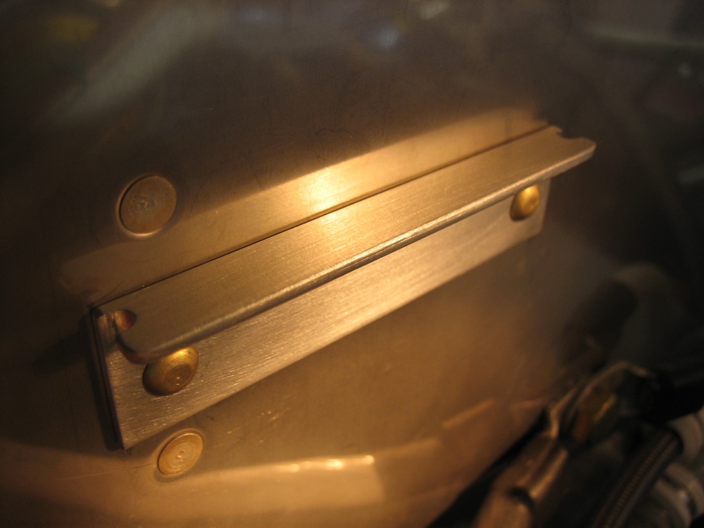
Fabricated Front Air Filter Support Angle

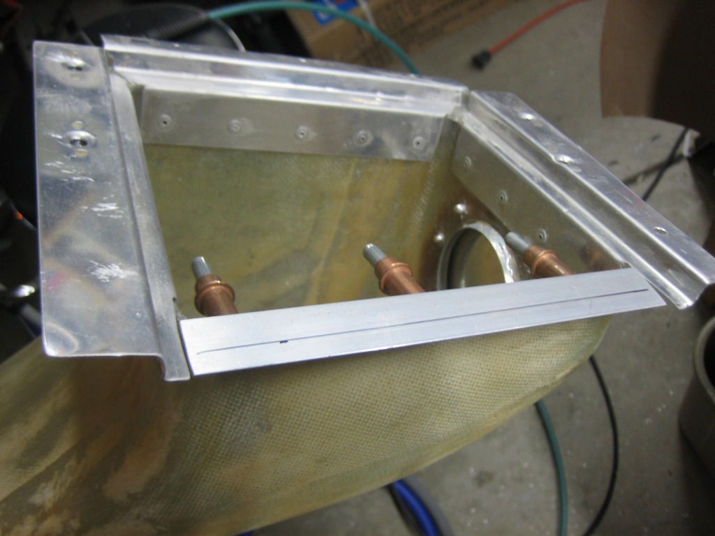
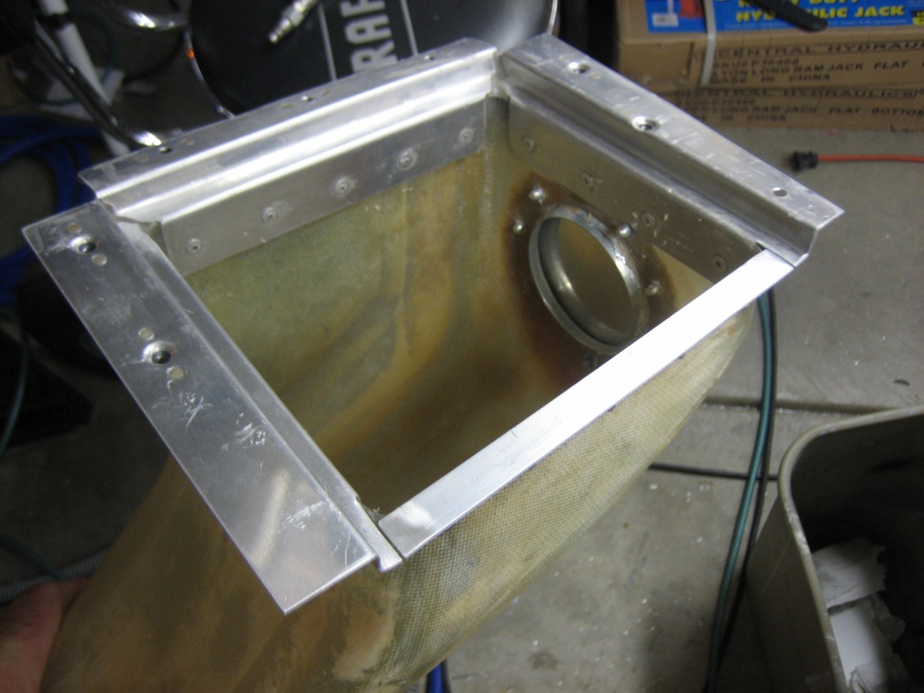
I fabricated the front air filter support angle tonight.  This is fabricated out of 0.063″ angle since it will only sit below the flange of the air filter and won’t wrap all the way around the edge and screw to the bottom of the baffles.  Using the thicker angle allows it to remain stiff enough to support the flange of the air filter.  I’m going to cut it off at the black line which is aligned with the edge of the air filter.  I’ll have to trim the inlet to the cowl back a bit to provide enough clearance to allow it to be installed.

Fabricated Prop Governor Control Cable Attach Bracket

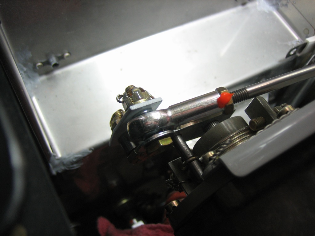
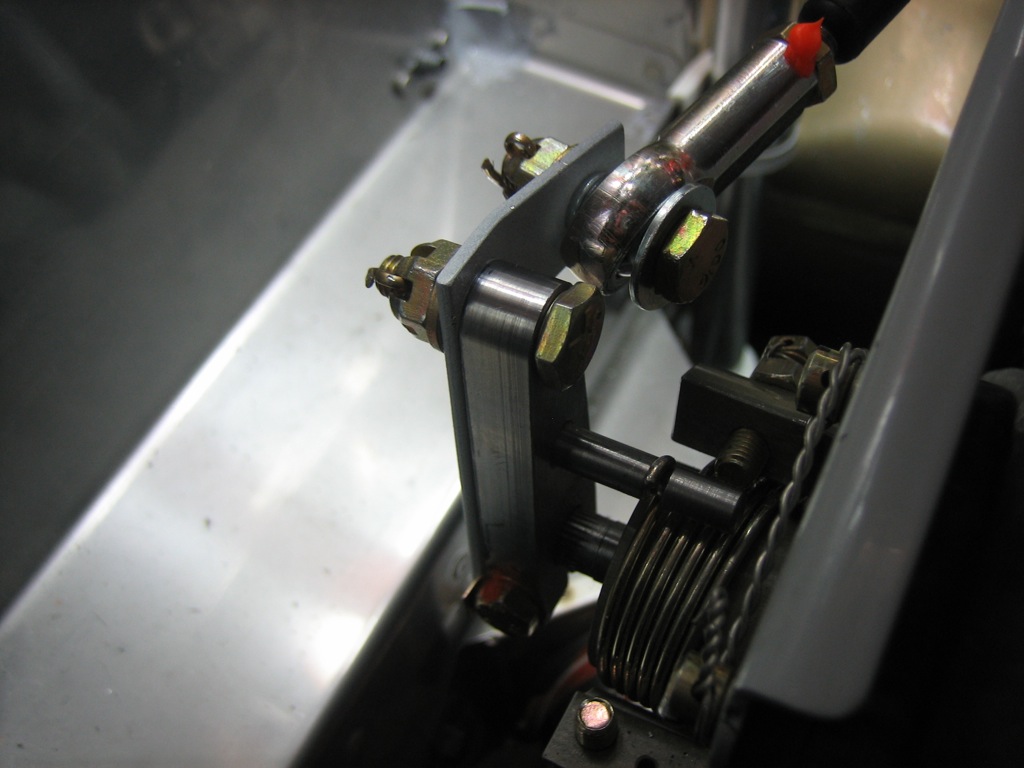
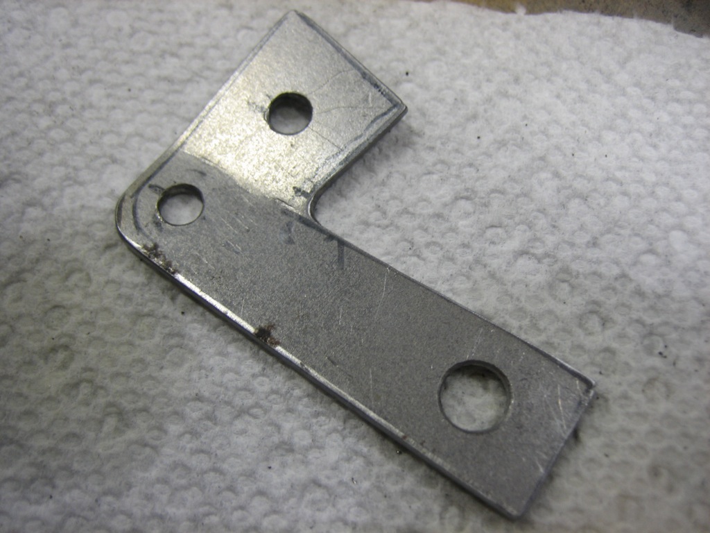
I’ve been trying to decide how I’m going to attach the prop governor control cable rod end bearing to the prop governor arm.  The issue is that the rod end bearing has to be installed with various washers to allow the bearing to have some freedom of movement and some protection in case the bearing fails.  This requires an AN3-11 bolt which is too long to insert from the front side of the arm (between the governor and the arm). Reversing the bolt and installing it from the aft side doesn’t work either because the bolt ends up hitting one of the screws around the perimeter of the governor head.  Van’s specifies an AN3-10A bolt, but that’s still too long and I really don’t think it’s a good idea to use a self-locking nut anywhere related to the engine control cables.  I spoke with John DeJoris at Aircraft Propeller about this issue, and he suggested using one of their adaptor brackets.  None of their stock ones looked like it would work, but it gave me a great idea how to make one.  I fabricated this little bracket from some 16g sheet steel.  It still needs to be cleaned up and powder coated, but this is how it will be installed.  There is a 1/4″ hole that fits over the center shaft to prevent the bracket from shifting.  It’s attached to the arm at the end with a short bolt and castellated nut.  There is a flange that sticks out and has an extra hole for the bolt that attaches the control cable.  This hole is positioned 1.5″ from the pivot point just like the hole in the arm, so the cable throw is identical.  Since this offsets the attach point from the arm, I needed to turn the control head to allow the arm to be moved through the whole range.  While this could probably have been done with the governor on the engine, I decided to pull it off and do the adjustment on the bench.  I’m really glad I did too.  It was pretty trivial to pull and replace, and it was far easier redoing all of this safety wire on the bench.
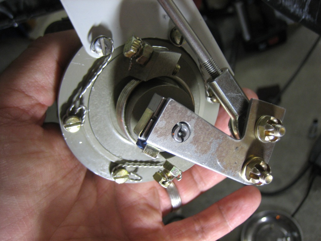
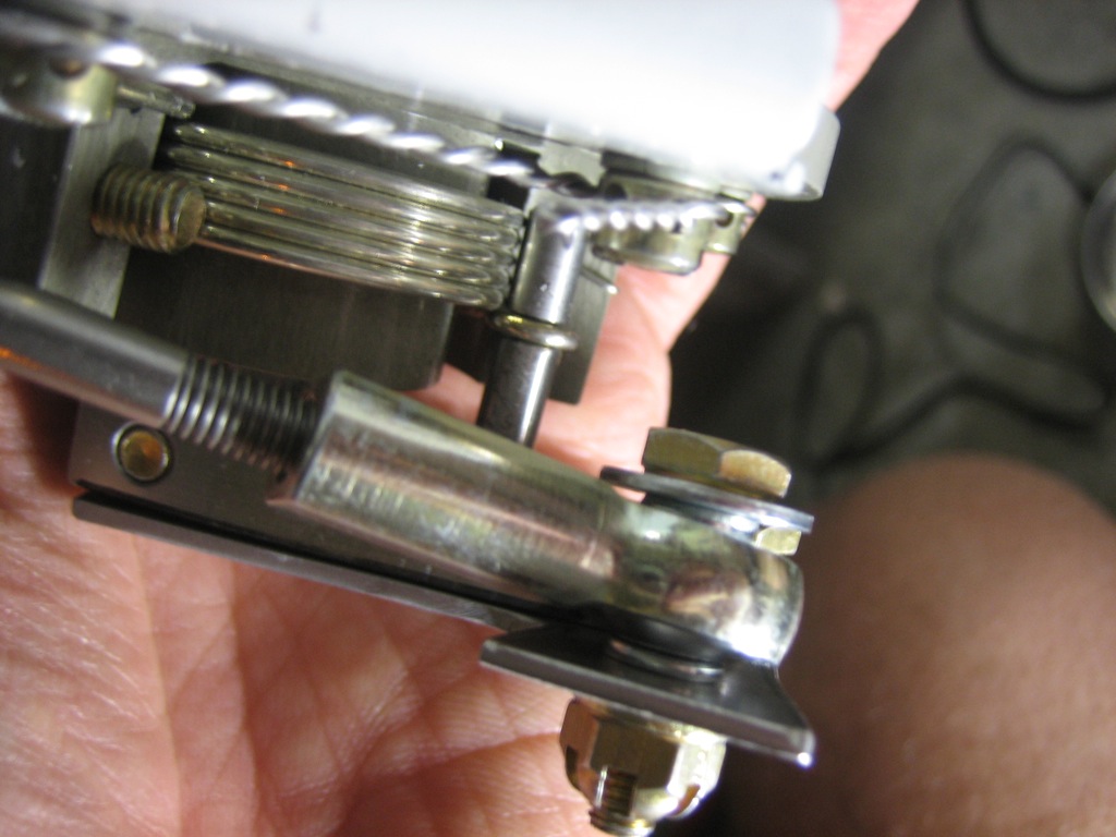
Here you can see that the bracket has a bend in it so that the rod end bearing doesn’t attach at such a steep angle (ignore the bearing alignment here; I hadn’t installed the jam nut to keep it from twisting).
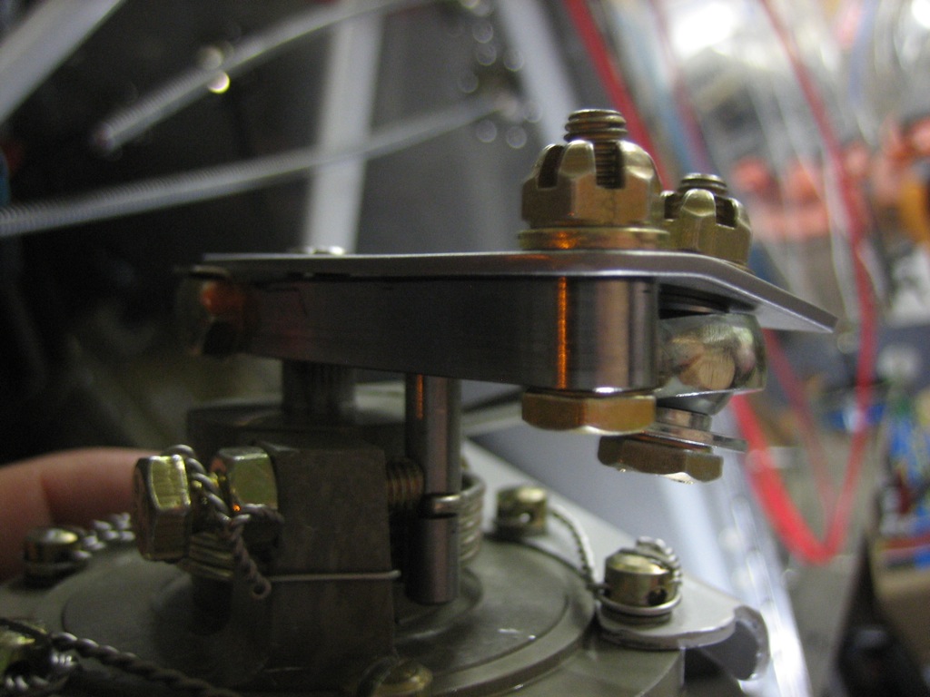
Here’s a good shot of how much better the bearing alignment is with that bend.
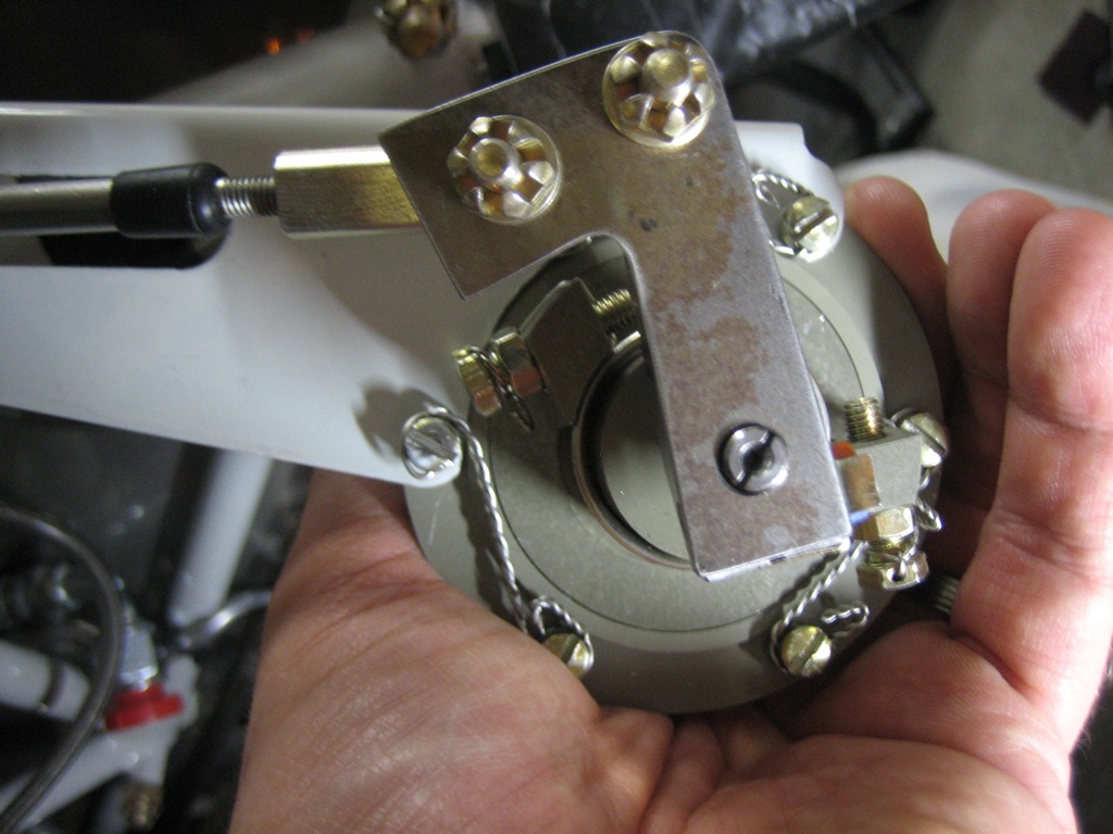
Here’s the control arm at the fine pitch stop.  You can see the arm is a lot farther around (clockwise) than would work if the cable attached directly to the arm.
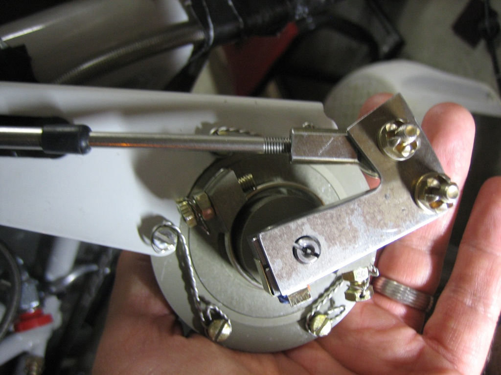
Here’s the control arm at the coarse pitch stop.  You can tell from the last picture and this one that the overall throw is biased towards the fine pitch stop.  This works beautifully because you’re pulling against a spring as you move towards the coarse pitch stop, but you’re gaining mechanical advantage as you pull because the cable and arm become more perpendicular.  This means that the pull feels pretty linear.  When I had the throw more evenly spread, the control cable required a fairly hard pull near the end to get the arm near the coarse pitch stop because you lost mechanical advantage and the spring force was the strongest.
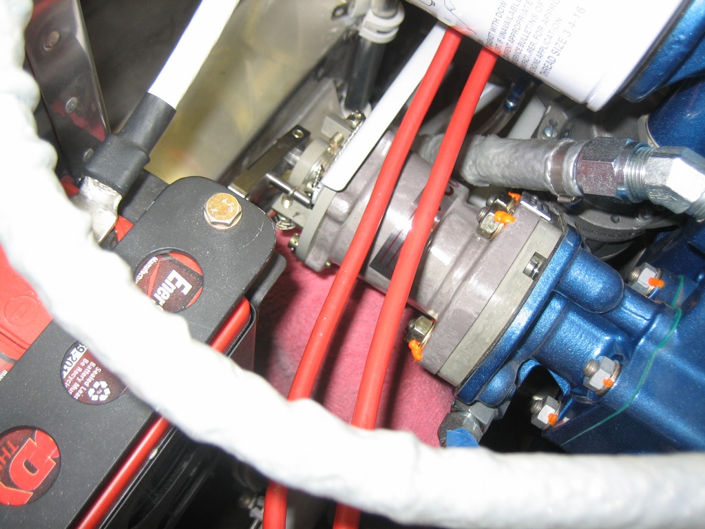
After getting everything adjusted, I reinstalled the governor with new washers and lock washers, and then torqued/sealed the attach nuts.
Here’s the finished bracket.  All it needs now is some cleanup and powder coating.
Added Additional Snorkel Attach Screw

I got back from Oshkosh a few days ago.  I flew with the Bonanzas to Oshkosh group in a buddy’s A36.  The show was great and the flight out there and back was a hell of a lot faster than our flight in the Cardinal a few years ago.  I thought I was done with the major purchases, but Dynon announced a new ADS-B receiver that will ship this fall, so I need to find a spot for that in the plane.

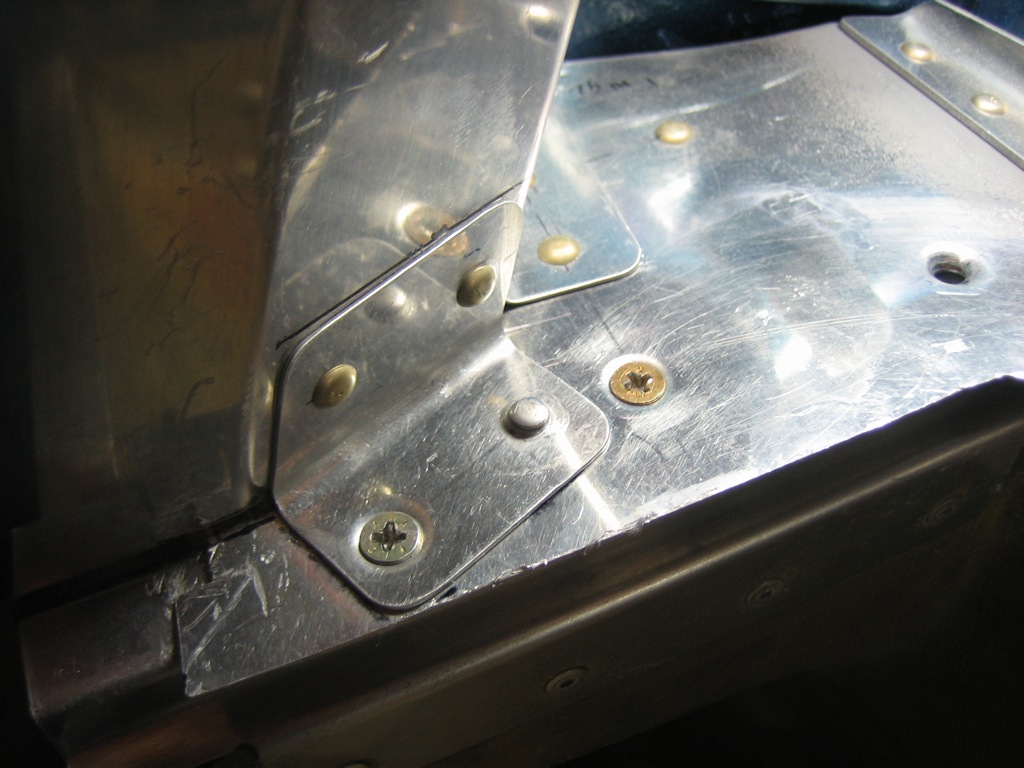
I’m waiting on some hardware to wrap up the propeller governor control cable, so I decided to try wrapping up the snorkel to baffle intersection.  The aft and outer snorkel flanges each have three screws, but the inner only had two.  At the forward end of the inner side, the bracket that ties the baffle floor to the wall surrounding the flywheel was right where the third screw would go.  After taking some measurements, it looked like the forward rivet hole would be fine for an additional screw.  I dimpled the aft hole for a flush rivet (flush on the bottom) and then dimpled the forward hole the other way for a #8 screw.

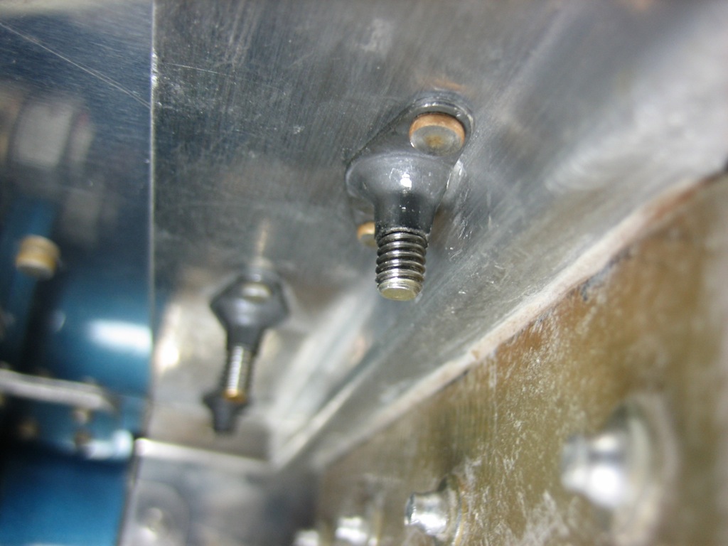
I had to grind away most of the edge of a K1100-08 nutplate to clear the bend in the flange, but this screw tightened up the forward end of the snorkel to baffle connection noticeably.  I now just need to trim the cowl to clear the front edge of the snorkel.

Finished Attaching Propeller Governor Control Cable

I received my parts order from Aircraft Spruce, so I decided to wrap up the propeller governor control cable.  I powder coated the bracket I fabricated and installed it to the governor control arm with an AN3-6 bolt and castellated nut.  I then attached the rod end using an AN3-7 bolt and castellated nut.  Both bolts are short enough to easily be removed without hitting the governor head.  Here’s the arm against the fine pitch stop.

And here’s the arm against the coarse pitch stop.  I’m super happy with this bracket.  It solved all of the issues that builders run into when using the PCU5000 governor with the Van’s bracket.

Resumed Work on Cowl

I haven’t touched the plane in a month, but I have a really good reason…honest!  First, I’ve been really busy at work, but what’s really killed all of my free time is that we bought a new plane!  We’ve finally outgrown the Cessna Cardinal that has been our family plane for a number of years now.  Even though the kids are still small, we’re basically right at gross weight with full fuel and baggage.  It’s also pretty slow and has pretty anemic climb which is important around here.  I’d been thinking about building an RV-10 after I finish the 7, but the ride in my buddy’s A36 Bonanza changed my mind.  I ended up buying a 1/4 share of a 2001 turbo-normalized A36 Bonanza with really low time in fantastic shape.  The search itself took quite a lot of time, but I’ve also been taking the Advanced Pilot Seminars course to learn to fly it lean-of-peak as well as the BPPP course to learn about how to fly the aircraft.  I’ve also been reading books and articles in preparation for the transition training that starts next week.

Anyway, a month is way too long, so I decided to use the long weekend to get restarted.  I prepped the lower side hinges and riveted them to the cowl with some West Systems G/Flex epoxy which will stay more flexible than their 105 epoxy.

I used some AN426A rivets to avoid crushing the fiberglass.  This is very slightly recessed from the side of the fuselage, but that’s perfect because I’m going to add a layer of lightweight cloth over these rivets and then a coat of dry micro so that it can be sanded perfectly flush with the fuselage.

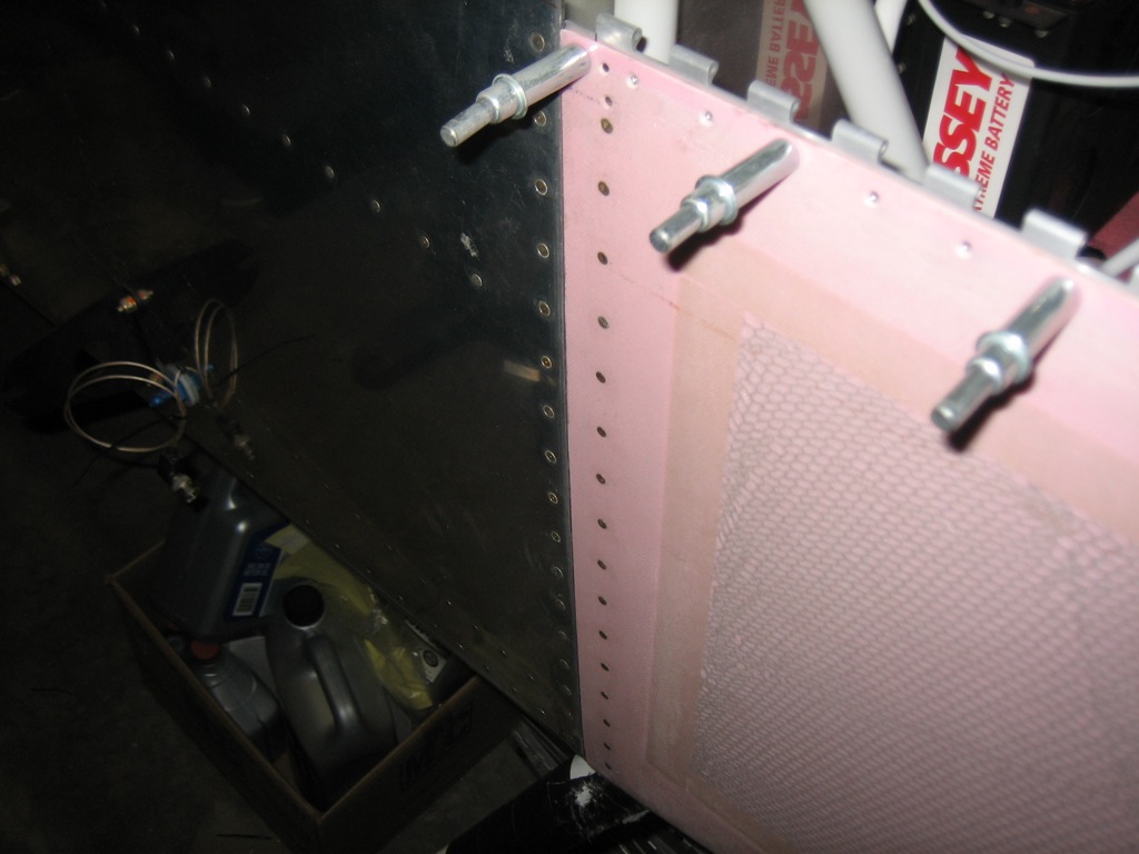
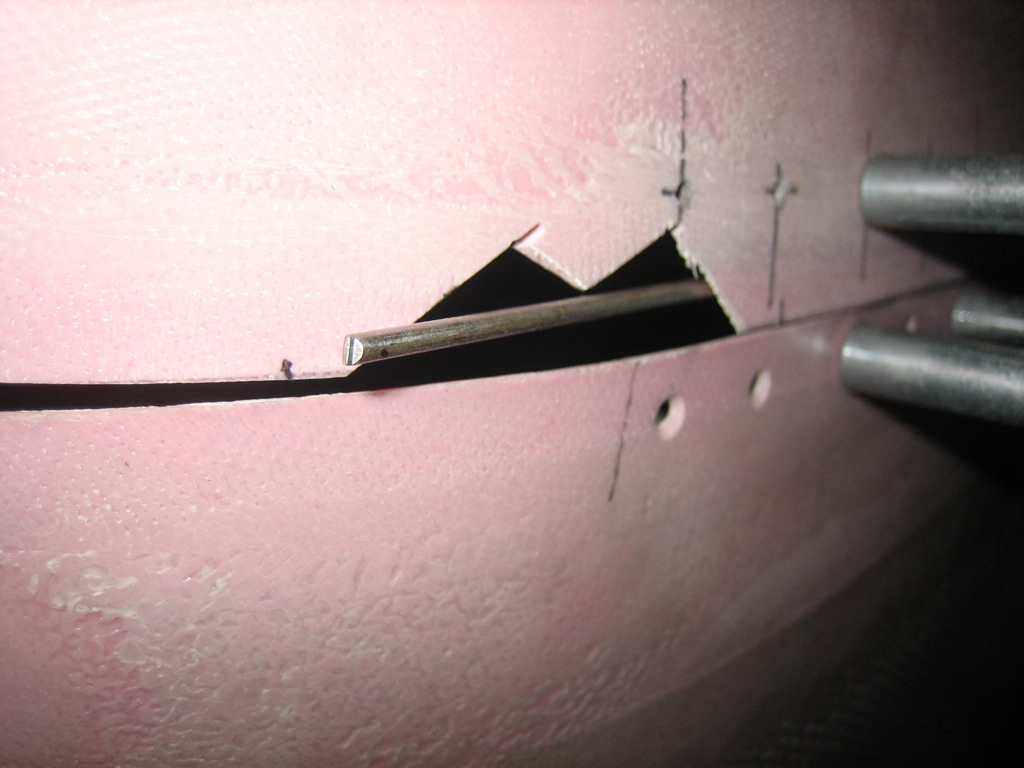
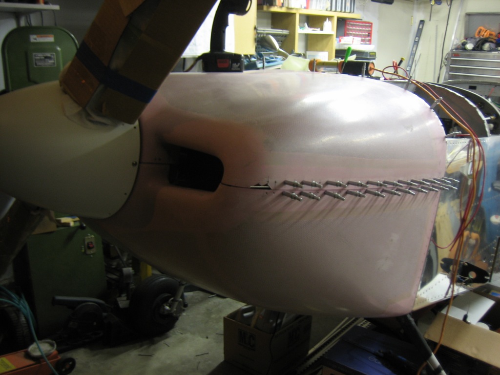
I also made a really rough cut in the side of the cowl to insert the hinge pins that attach the sides of the cowl together.

Here’s a wider shot to show where these pins stick through.

Riveted Side Hinges on Upper Cowl

I riveted the side hinges on the upper cowl this afternoon.  Like all of the hinges that are riveted to the cowl, these are additionally secured with epoxy.

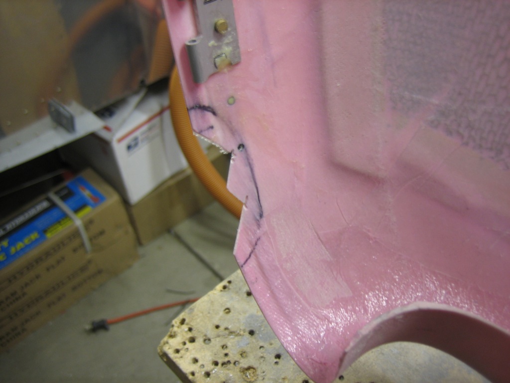
Here’s the other side of that rough cut in the side.  The oval mark is the approximate outline of the covers that will secure (and hide) the end of the hinge pin.  All of that part of the cowl will be cut away, so it didn’t matter that this was such a gross cut.

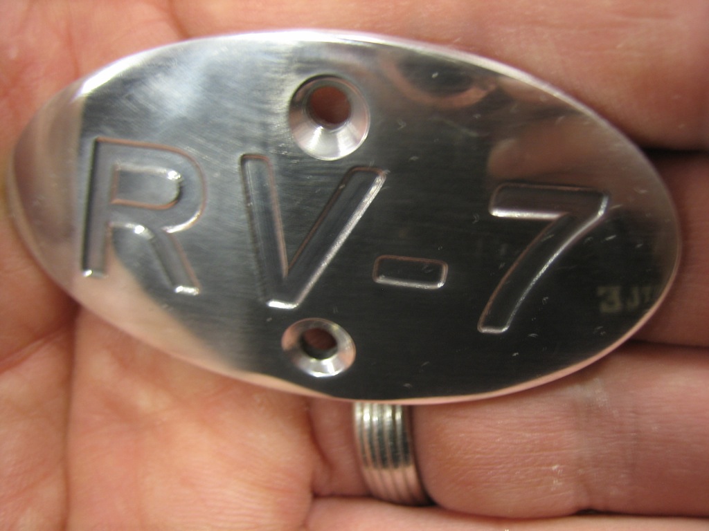
Here is one of the hinge pin covers.  These are made by Aerosport Products and they’re really nicely machined.  They come with a set of blanks that are slightly oversized to use when modifying the cowl to provide clearance for paint.  These will look great when everything is completed.

Prepped Firewall Hinge on Upper Cowl

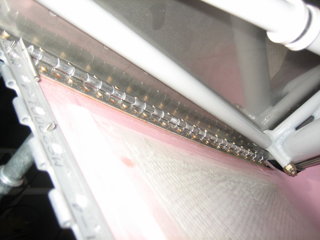
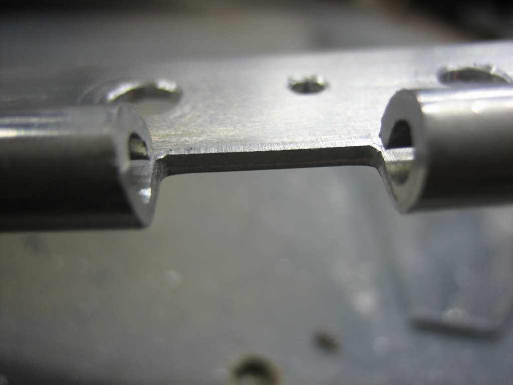
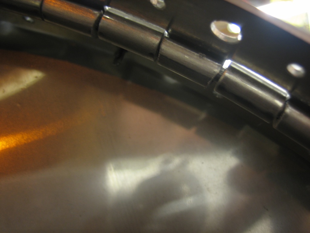
I spent an hour or so tonight prepping the firewall hinge on the upper cowl.  Because of the tight curvature of the cowl in this area, the hinge eyelets bind together.  This wasn’t a problem when fitting the hinge initially, but it has to be corrected before the hinge is riveted to the cowl.  I filed bevels in each eyelet in the region of the hinge with the tight curvature.

Here you can see that the bevels provide clearance between the eyelets.  I only did this to the forward half of the hinge, and only in the last foot or so on each end.

Fabricated Upper Cowl to Firewall Hinge Pins

Up until now, I’ve been using some 0.120″ aluminum hinge pins to keep the hinge halves aligned during the cowl fitting process, but these have to be replaced with stainless steel to provide the necessary strength when flying.  Van’s recommends using 0.090″ stainless steel pins to make it easier to insert them because of the tight curvature, but other builders have complained that this makes for a sloppy fit and that you can make the 0.120″ stainless steel pins work if you bend them right.  I cut some hinge pin stock to length and spent 30 minutes or so getting the curvature right so that it essentially follows the curvature of the firewall without any force on it.  I then sharpened the end of the pin so that is won’t get hung up on the edges of any eyelets.  After putting the bends in the ends of the pins as shown here, it was pretty easy to slide them in and out.  I need to fabricate a little clip on the firewall to retain them and keep them from sliding out in flight, but that should be pretty straight forward.

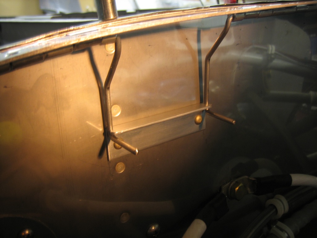
Fabricated Upper Cowl Firewall Hinge Pin Retainer

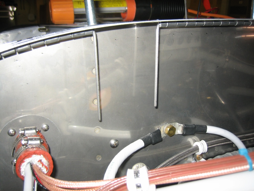
I spent a little more time tonight trying to diagnose the servo issue without any luck.  I put that aside and decided to fabricate a clip to keep the upper cowl to firewall hinge pins from sliding out.  It’s just a simple piece of 1/16″ angle with one leg cut down and some notches filed in each end.

The hinge pins need a few bends to make them run parallel to the firewall and to provide a handle to use to pop these pins in and out of the retaining clip.