Fabricated Front Ramp Brackets

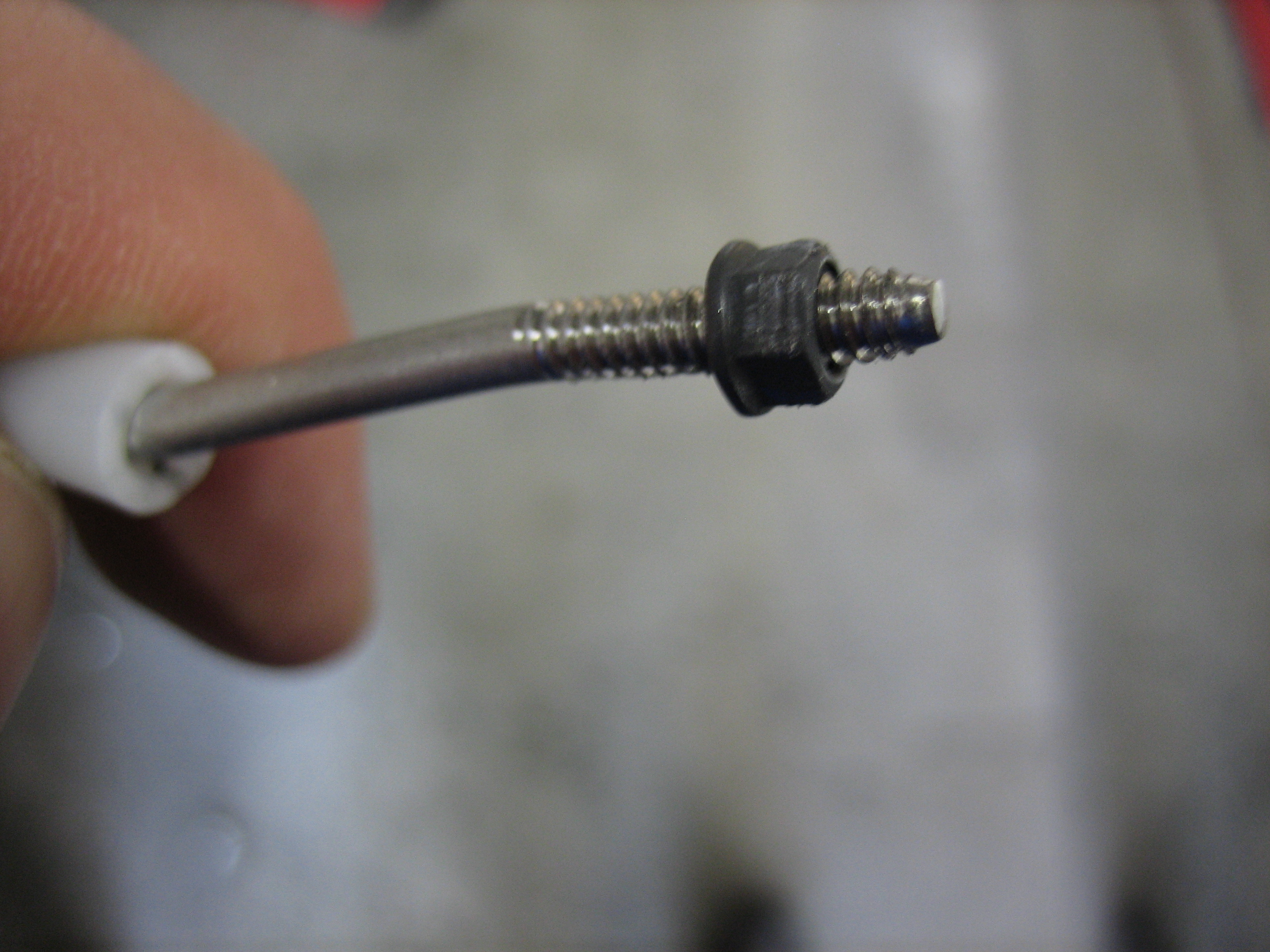
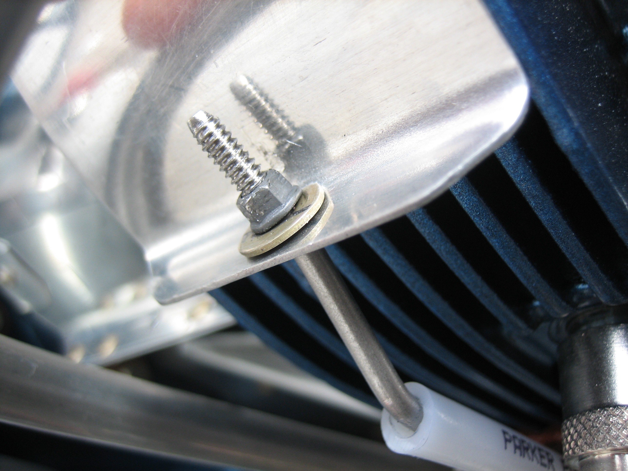
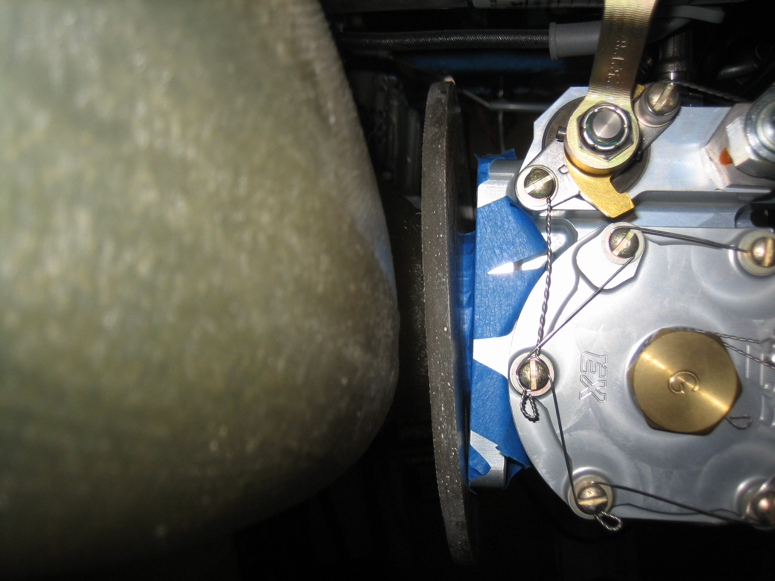
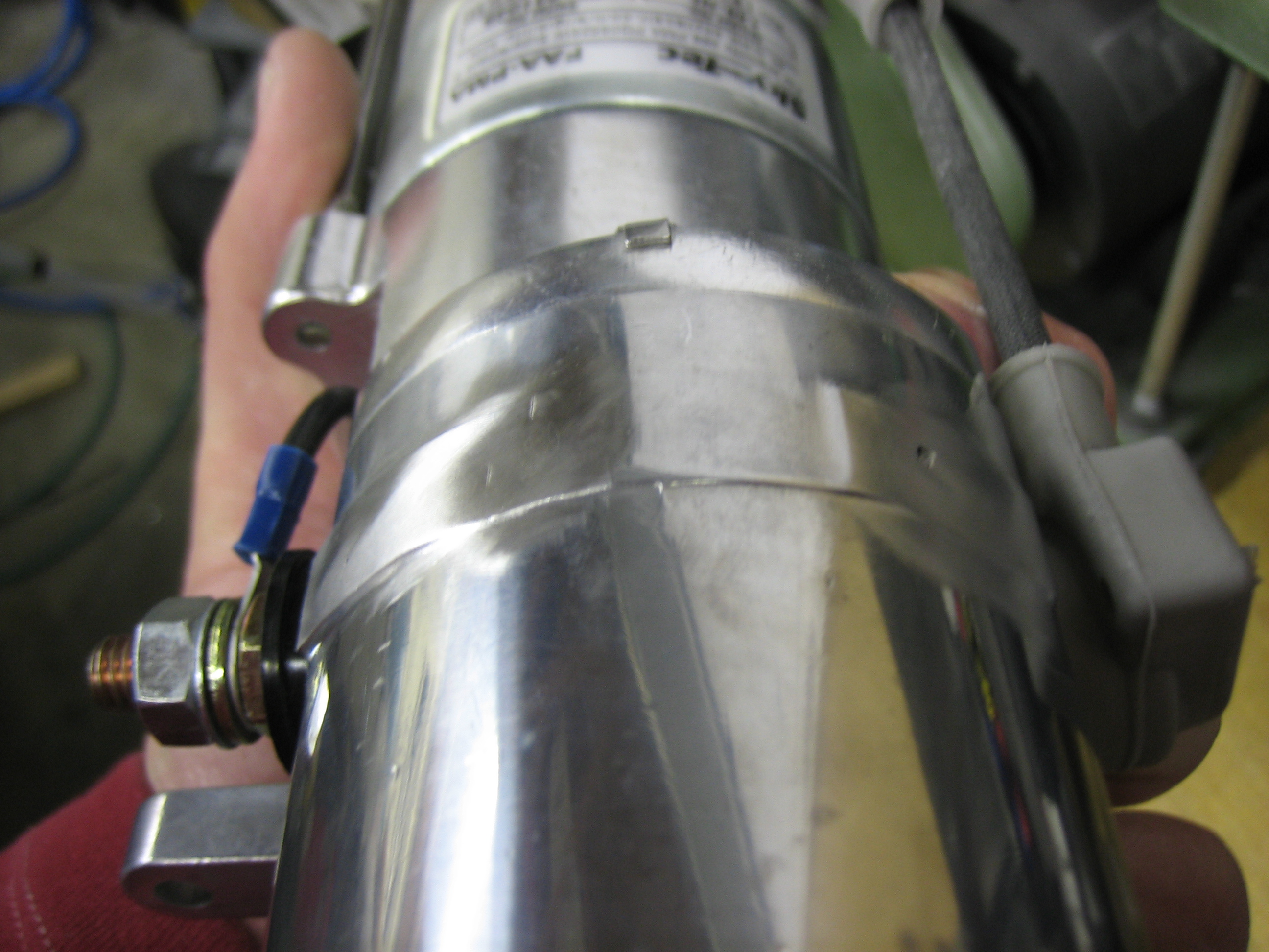
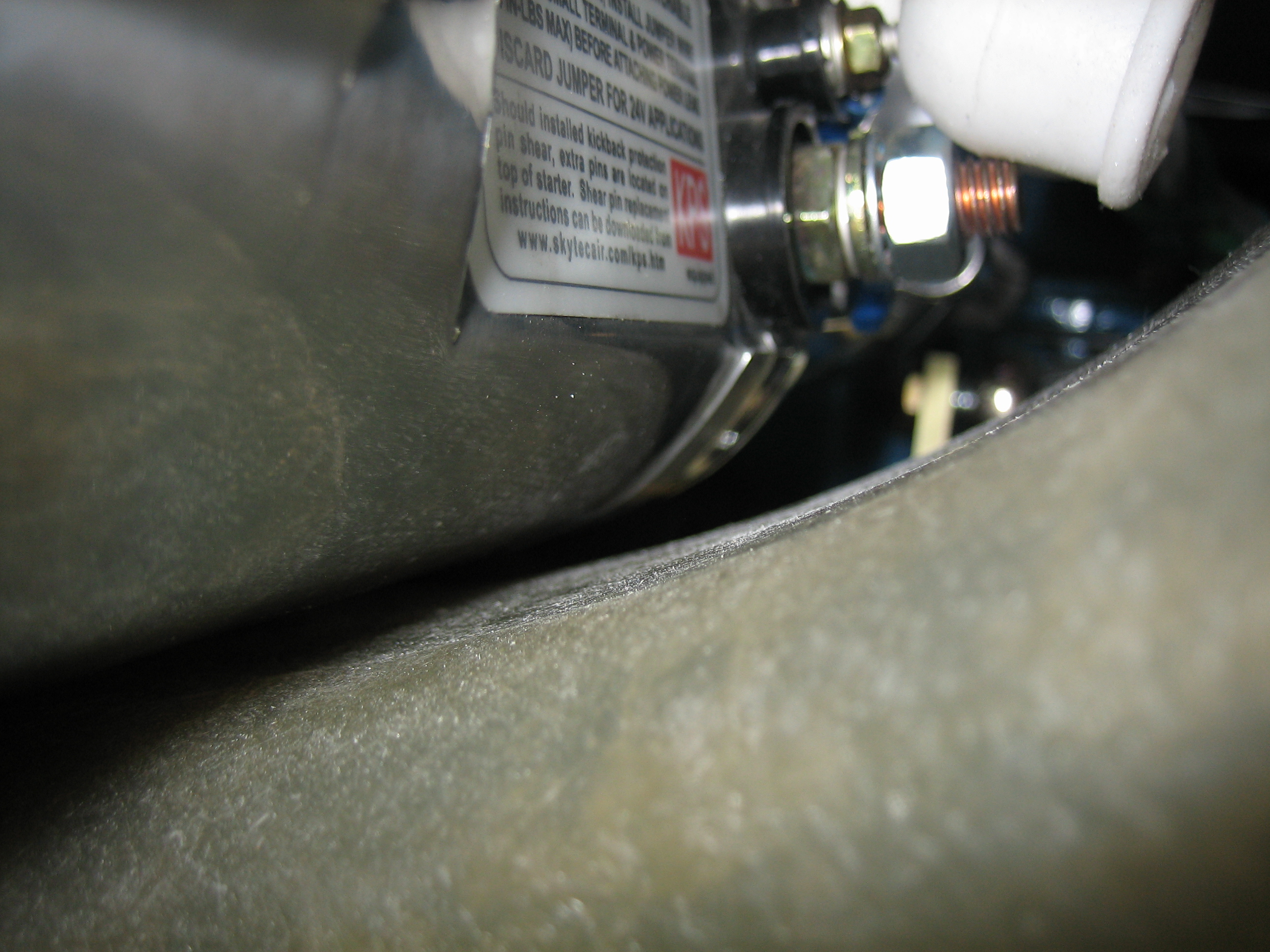
I never liked the old tach cover (see this entry).  Although it was safety wired, that didn’t prevent it from unscrewing and bouncing around behind the engine.  I recently found out that Andair made this nice machined tach cover with integral o-ring.  I swapped it out and safety wired it to the same spot on the engine.  There’s no way this is coming off.

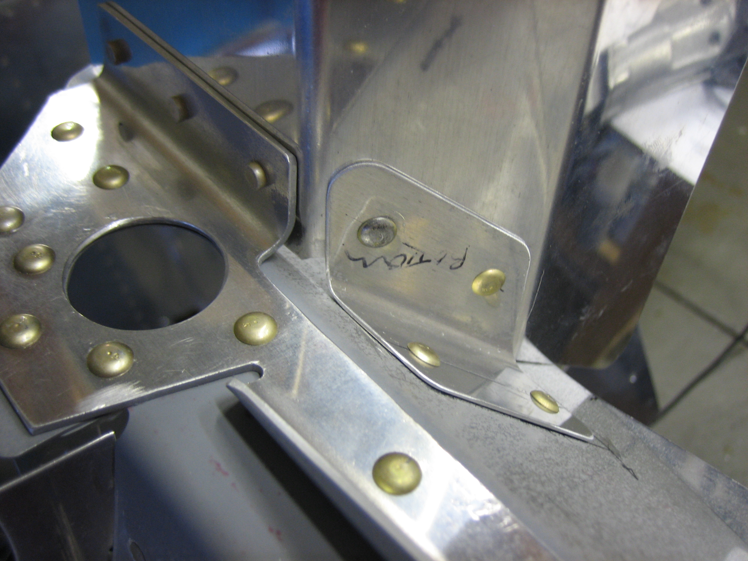
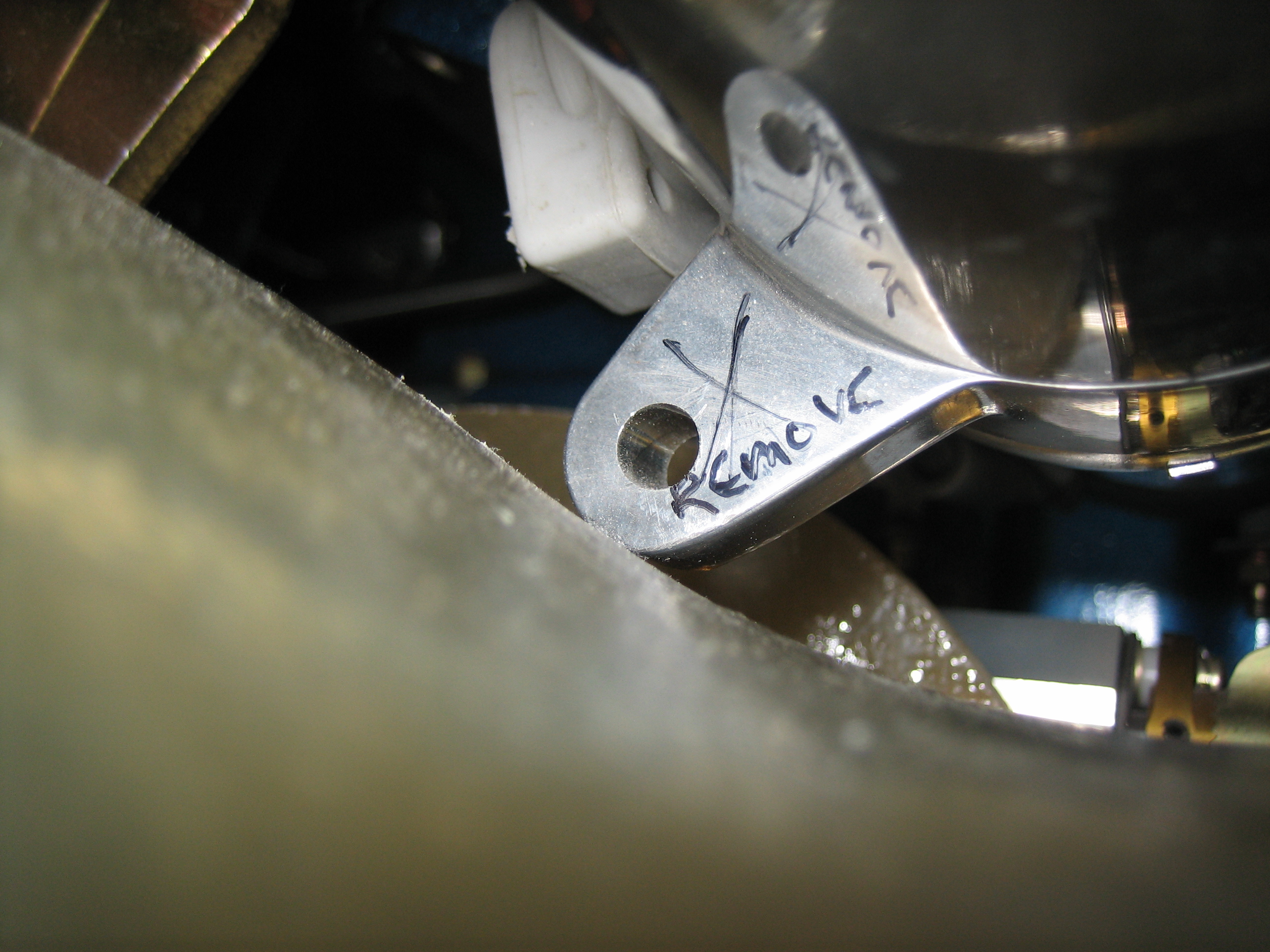
I fabricated the three front ramp support brackets.  This is the one that ties the right ramp to the right center baffle.  I left the bottom flange long on both ends until I know the left-right position of the vertical face.  I’ll then drill this to the right ramp and cut the ends of the flange parallel with the angle on the left.

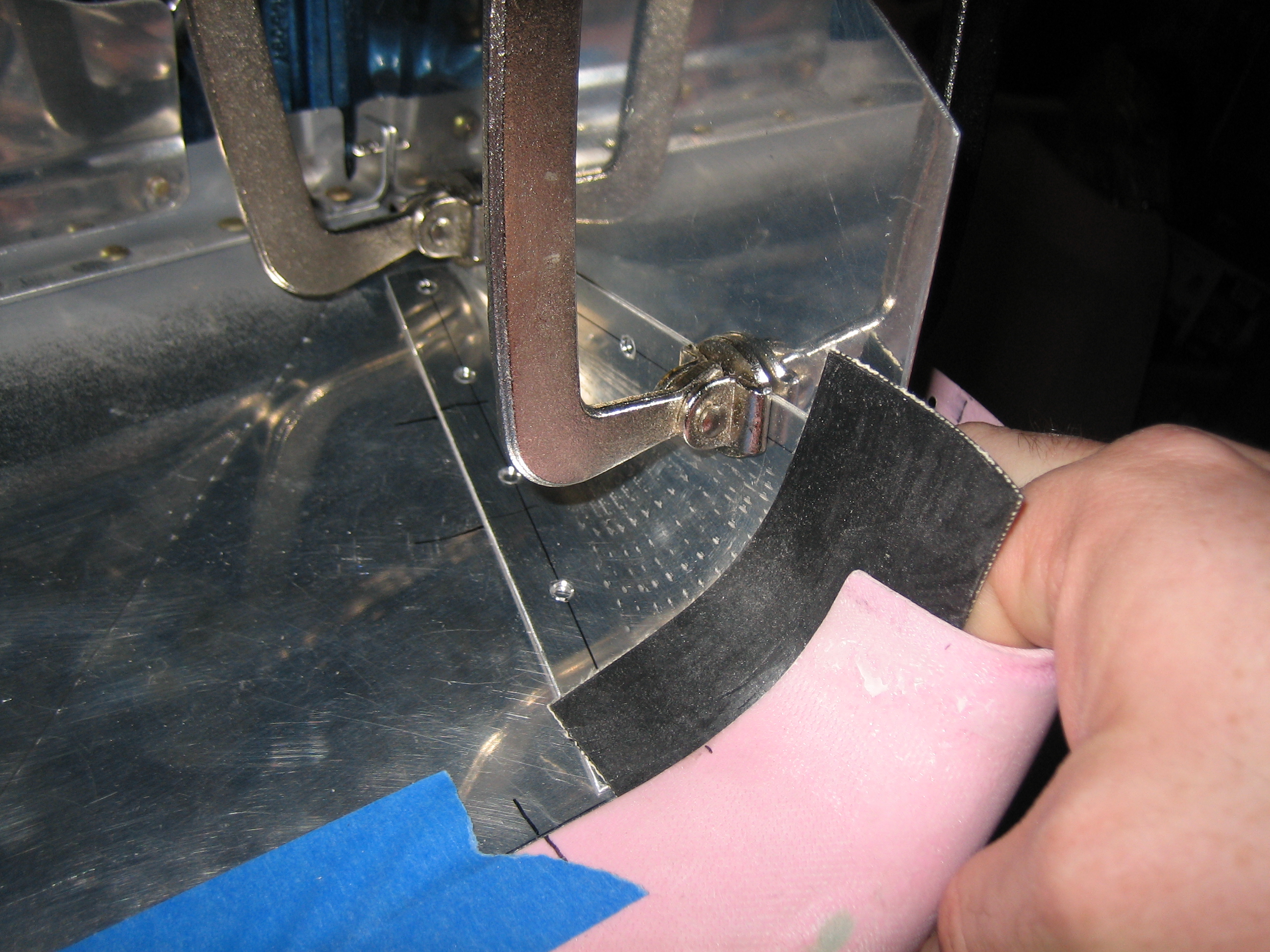
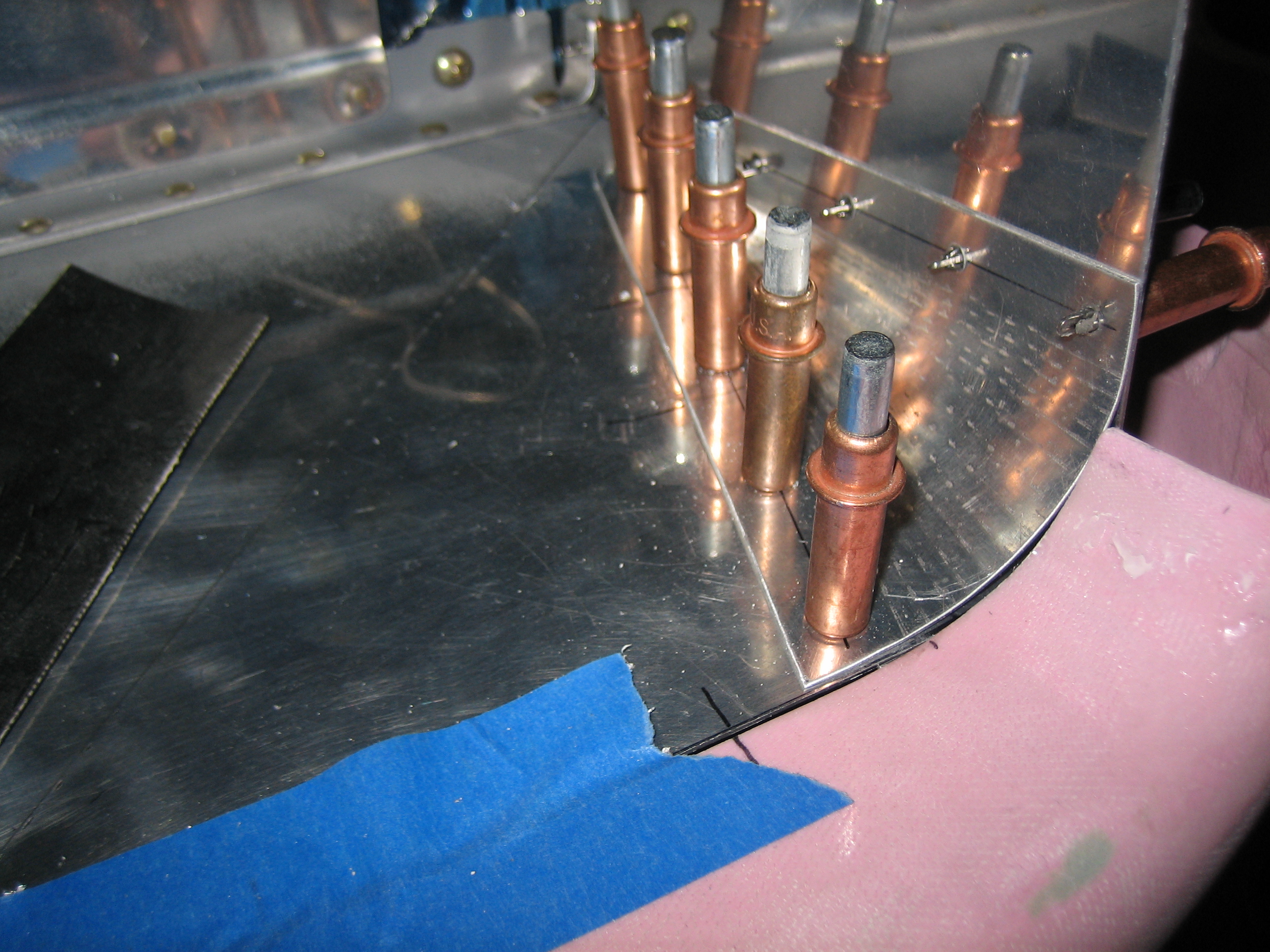
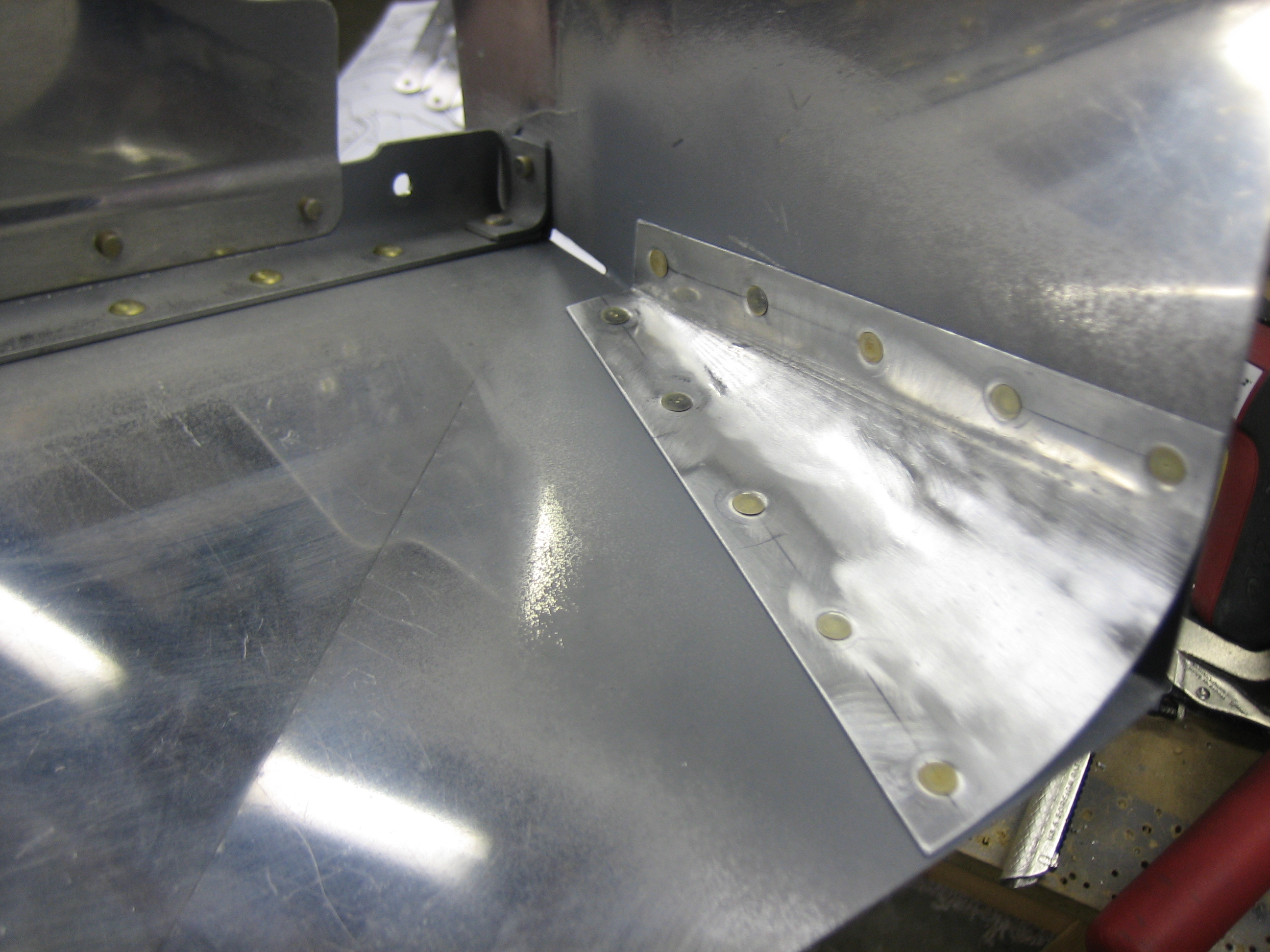
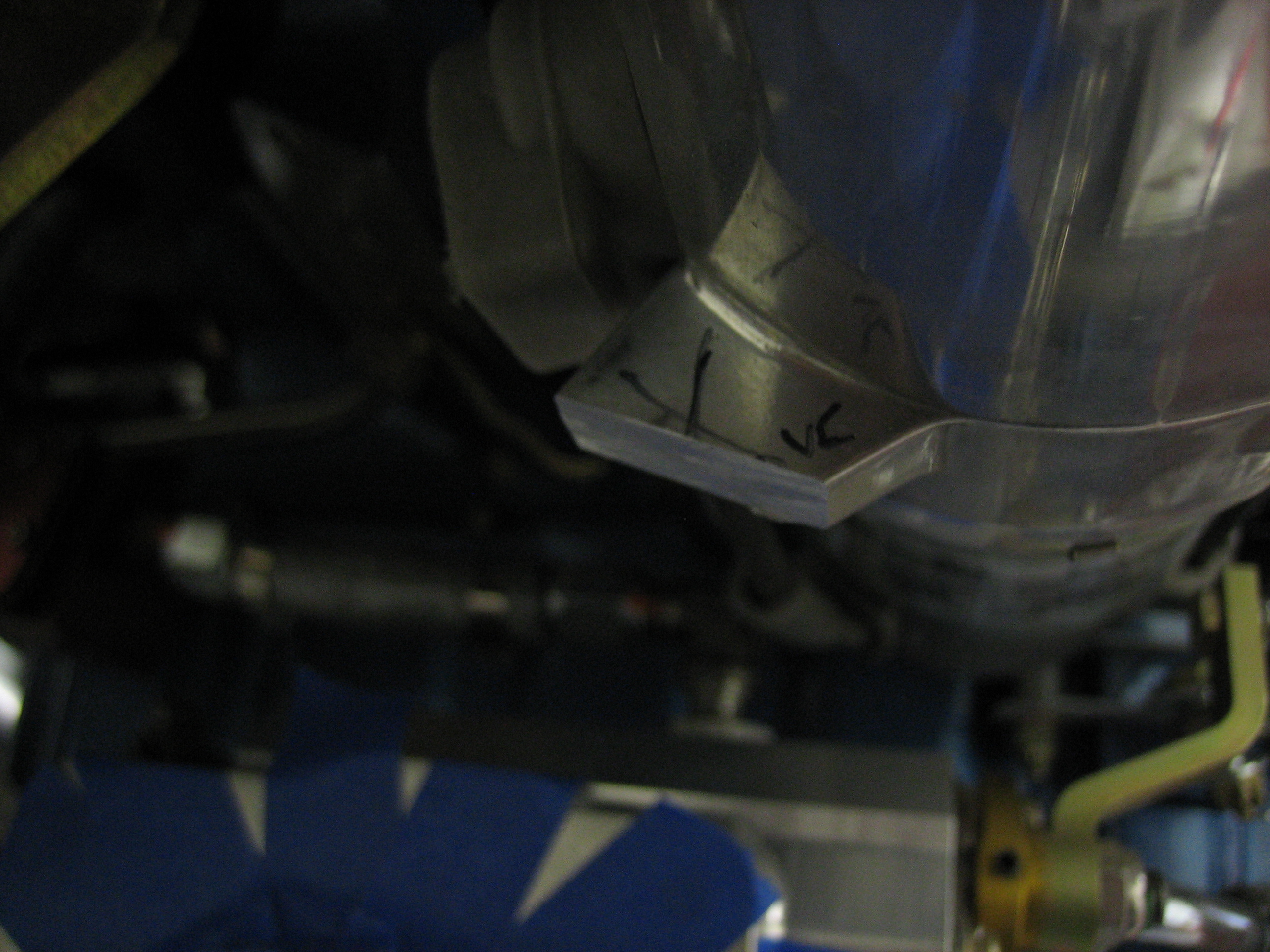
These are the brackets that tie the left ramp to the left center baffle.  I positioned the vertical face against the side of the lower cowl inlet (with a piece of baffle seal between them) and then drilled the support on the left to lock in the position.  I then pulled the lower cowl and back drilled the support on the right through the existing hole in the ramp and support that sits just under the ramp.  I then pulled the bracket and drilled two more holes in line with that hole and then match drilled them to the ramp.  Getting all of this in the right position was a little tricky until I figured out the order, but everything worked out nicely.

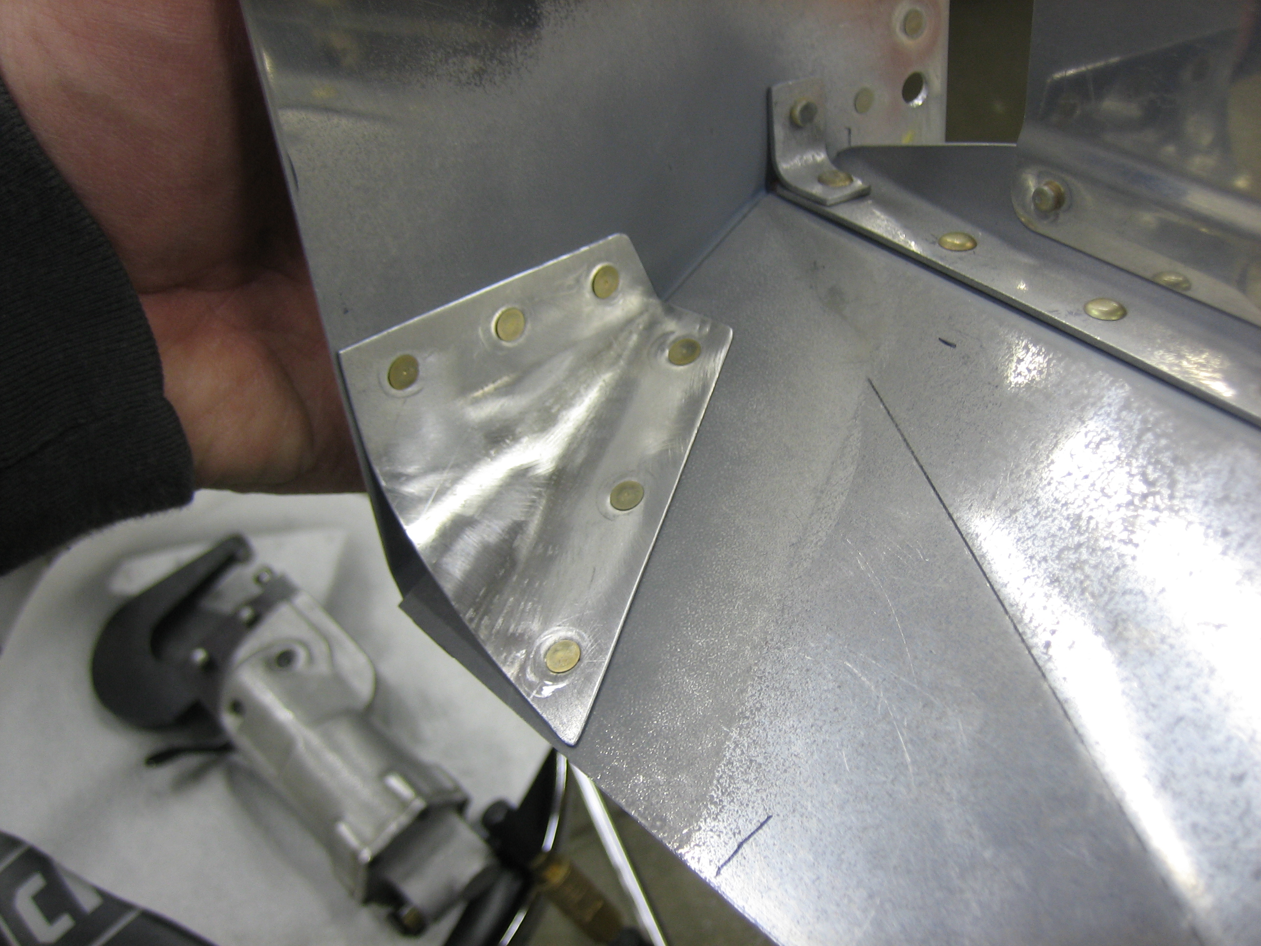
I deburred everything and riveted the support brackets to the ramps and front center baffles.  The plans call for universal rivets here, but I might have to swap the rivets on the left bracket out for a flush head since the baffle seal material will rest here.

Here’s the bracket for the right ramp.

Riveted Conical Gussets

I finished drilling the side baffle flanges to the ramps and then deburred and dimpled everything.  After a quick priming of the mating surfaces, I riveted the conical gussets in place.  Here’s the right gusset.  I also riveted the little clip in the upper right of the picture to the side baffle.

Here’s the right conical gusset.  These ended up fitting really nicely.  There quite a bit harder to install now since they’re so big.  They wrap from the centerline of the engine just behind the prop around the side of the engine and back past the front-most cylinders.

Worked on Baffle Connecting Rods

The bottom of the baffles need to be tied together to keep them tight against the cylinder fins.  You can either do this by using safety wire through some washers (to keep the safety wire from sawing through the aluminum baffles) and a piece of plastic tubing (to keep the safety wire from sawing through the cylinder head oil return lines.  I’m sure this works fine, but it seems pretty cheesy.  The other suggested approach is to use some stainless steel rod, bent to clear the cylinder head oil return lines and threaded for 6-32 nuts on each end.  I got started by fabricating the left outboard connecting rod.  This needed to be a little longer than the plans specified, and the angle of the bends at each end differs from the plans to make the threaded ends sit perpendicular to the baffle flanges.  I installed the optional plastic tubing to ensure that there would be no abrasion if this contacted the oil return line.  I tried threading the end, but the shitty Harbor Freight tap and die set I have is really junk.  I basically stripped the threads on the 6-32 die.  This junk is okay for creating threads on aluminum, but I need a decent tap and die set to do stainless steel.

Started Threading Baffle Connecting Rods

I picked up a much better tap and die set from Sears today and was able to easily thread the ends of the stainless steel rod I bent yesterday.  Unfortunately, the die cuts the threads a little deeper than a typical 6-32 screw, so the all-metal self-locking MS21042 nut spins freely.  I’ll have to further distort the threads in a vice to ensure these are self-locking.

Finished Fabricating Outer Baffle Connecting Rods

I finished fabricating the outer baffle connecting rods.  Here’s the one on the left side of the engine.

I put a fairly healthy curve in the rods.  This way they stay fairly straight even under tension.

Here’s the one on the right side of the engine.  Both outer rods touch the cylinder head oil return lines, but the curve I put in the rods causes it to just touch the oil line, not put pressure on it.  That plus the plastic cover on the rods should eliminate any abrasion on the oil lines.

Finished Baffle Connecting Rods and Started Snorkel

I finished up the inner baffle connecting rods.  Here’s the one on the left side of the ending.  Getting to the nut on the aft end of this rod is probably the toughest part of installing these.

And here’s the inner connecting rod on the right side of the engine.

Next, I got started fitting the snorkel.  The engine air inlet on this engine is in the front left ramp.  The air will flow through an air filter and then down through the snorkel and into the fuel injection servo here.  I took off the cover plate and measured the size of the hole.

The hole in the snorkel is 2.400″.  I took a roll of electrical tape and added some masking tape until this was just under that size.

I then taped the roll of tape to the front of the servo so that I could temporarily fit the snorkel.

The aft face of the snorkel isn’t sitting flush with the face of the fuel injection servo.

This is part of the problem.  The lower right lug on the starter is interfering with the snorkel.

And this is the rest of the problem.  Because of the shape of the snorkel, it interferes with the alternator mount.

I took a cutoff saw and removed most of the offending starter lug.  I’ll probably end up pulling the starter and removing the entire lug or lugs once I know for sure which ones need to be trimmed.

I also roughed out the cutout that needs to be made to clear the alternator mount.

I ended up having to cut even more from the snorkel to clear the alternator bracket.  I’ll cover this with glass once I know the final shape.

Finally, I spent a little time trimming the top of the snorkel.  I still have a bit more to do to shift the opening far enough inboard to clear the conical gussets.

Modified Starter

I pulled the starter off the engine and filed off the two lower lugs to provide clearance for the snorkel.

You can see here that with the snorkel in place and the lugs gone, there is right at 1/8″ of clearance between the starter and the snorkel.  This is the minimum clearance specified by the plans, and I needed to get it this tight to allow the snorkel to swing up far enough to place the inlet in the best part of the ramp.

Fit Snorkel to Fuel Injection Servo

With the snorkel in it’s final location, I marked the flange along the edges of the servo and cut them off.

I then drilled the flange for some 1/4″ hardware and temporarily bolted the snorkel in place.  I still need to do some trimming at the upper end to provide room for the filter.

Fit Air Filter Mounting Flanges to Snorkel

I trimmed the air filter mounting flanges and drilled them to the snorkel.  The 3/8″ clearance turned out to be perfect if you tuck the closest bend on the flanges up against the top edge of the snorkel.  This provides just enough room for the flanges to sit below the inlet ramp and lay flat.  The inlet ramp will need a bunch of modification before this can be fitted.  I hadn’t read through the snorkel instructions before fitting the left side conical gusset.  It turns out that this isn’t supposed to be used when installing the snorkel.  I’m going to leave it in place though since the alternate design won’t seal tightly against the cowl inlet.

Here’s how the air filter will sit in the top of the snorkel.  I’ll need to cut most of the inlet ramp away to allow air into the filter.