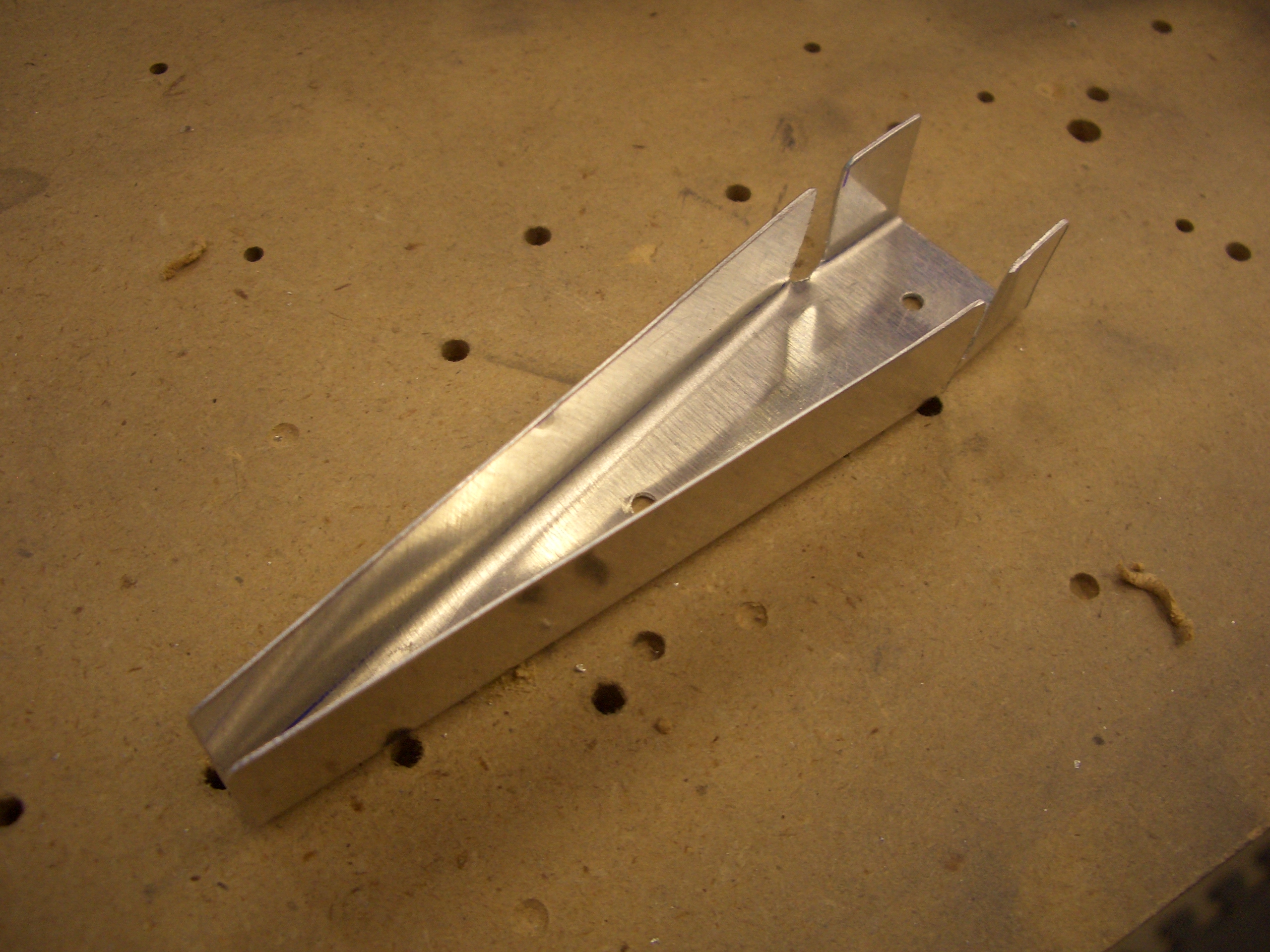
After researching this issue on vansairforce.net, I decided not to follow the plans again when it comes to the trim tab. The trim tab and left elevator skins come with little ears that are supposed to be folded together to close in the end of the surfaces. The problem is that many (most?) people end up not happy with these bends and either redo them (which would be expensive with the elevator skin) or live with it. The consensus seems to be to just cut off the ears and fabricate little riblets to fit in there. If you’re not happy with how these come out, you’re only wasting a few cents worth of scrap aluminum.
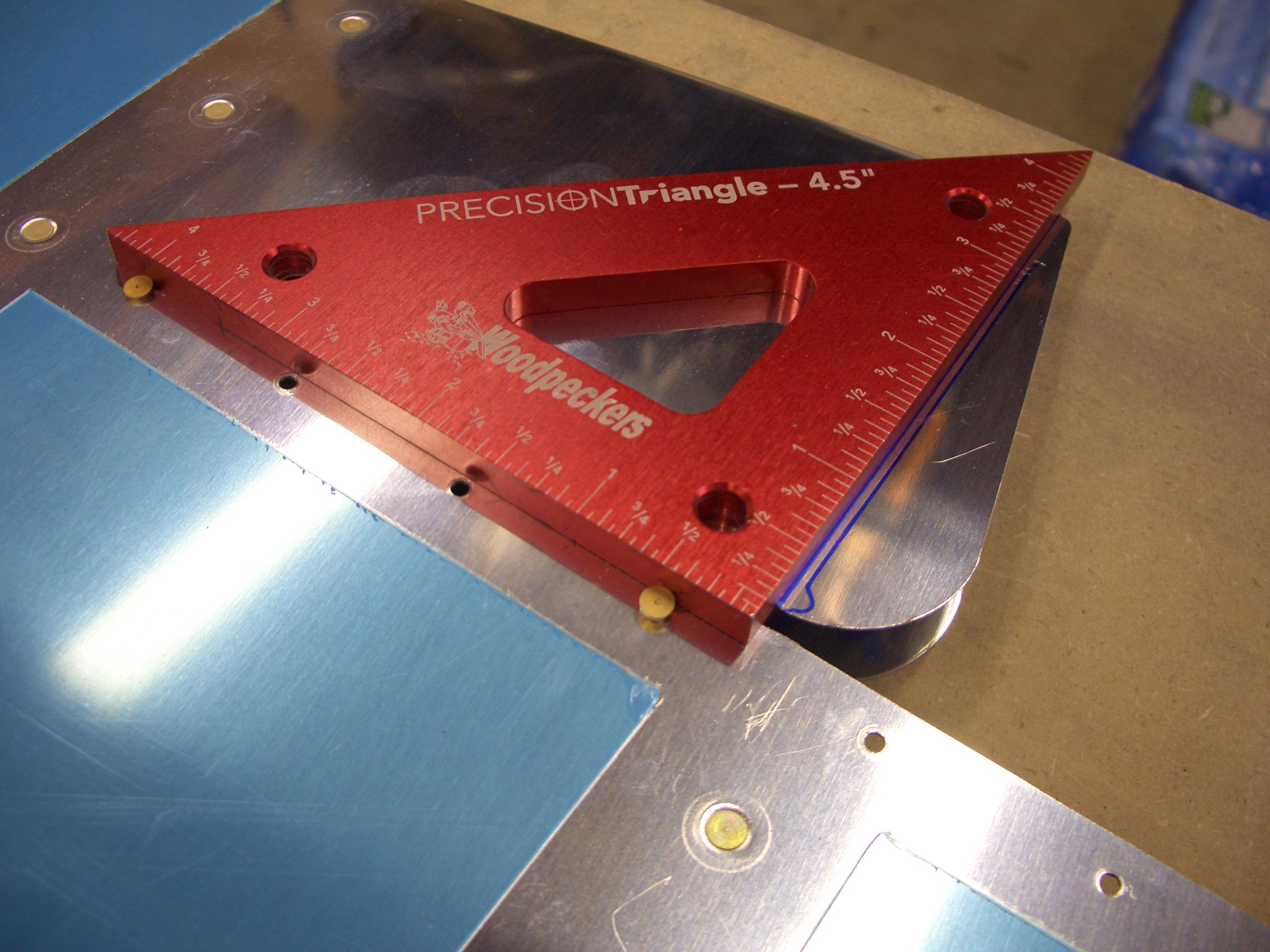
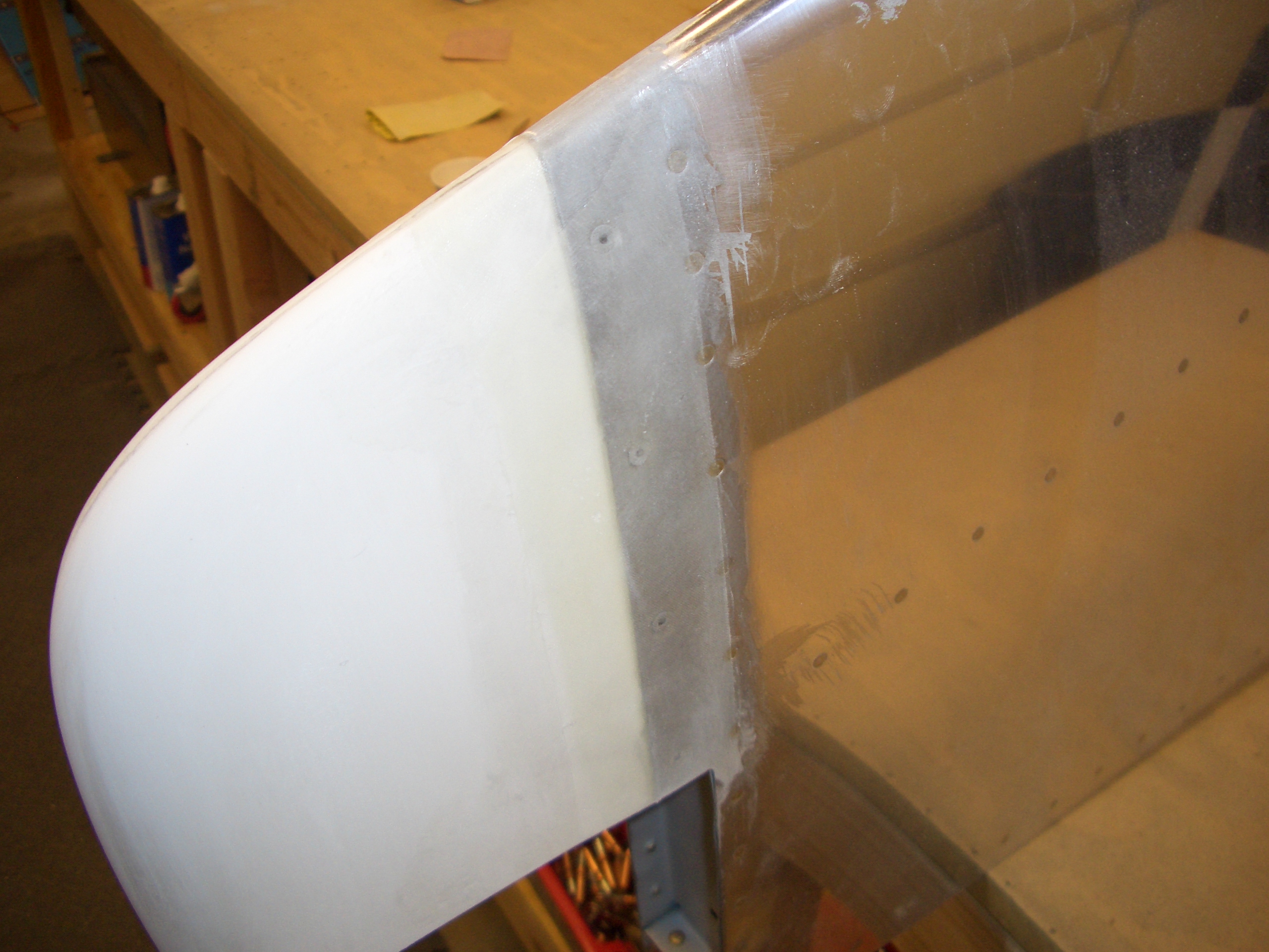
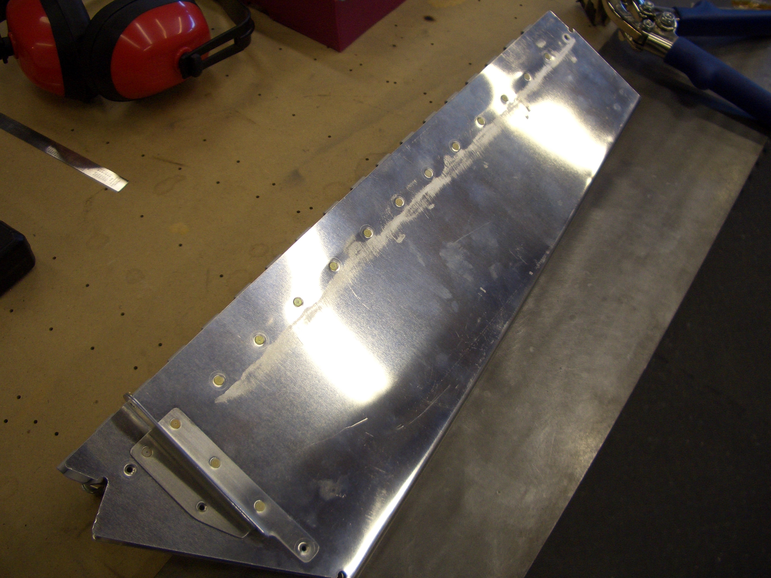
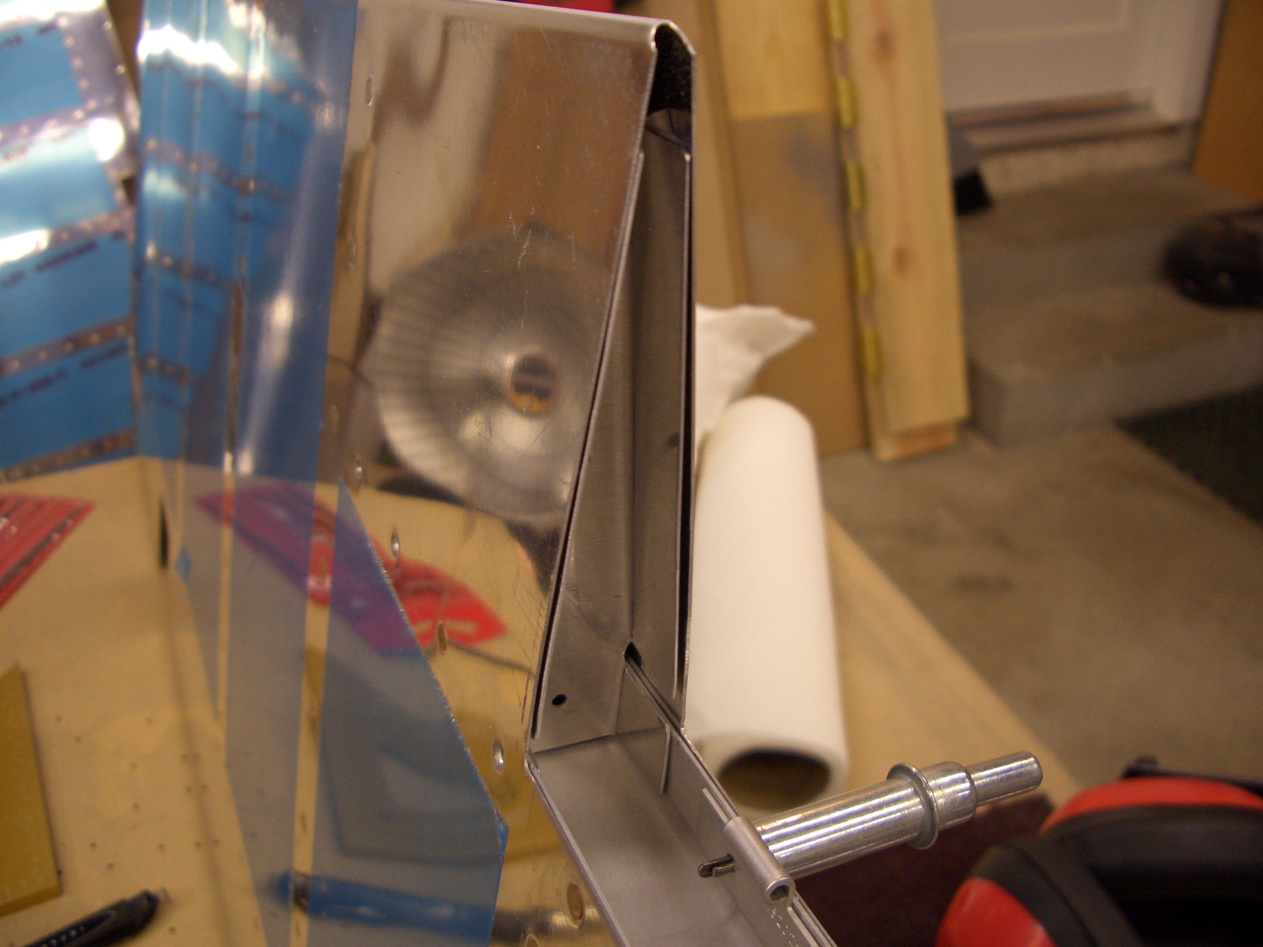
Here, I’ve cut off the ears on the trim tab and I’m ensuring that the cut line is perpendicular to the trailing edge.

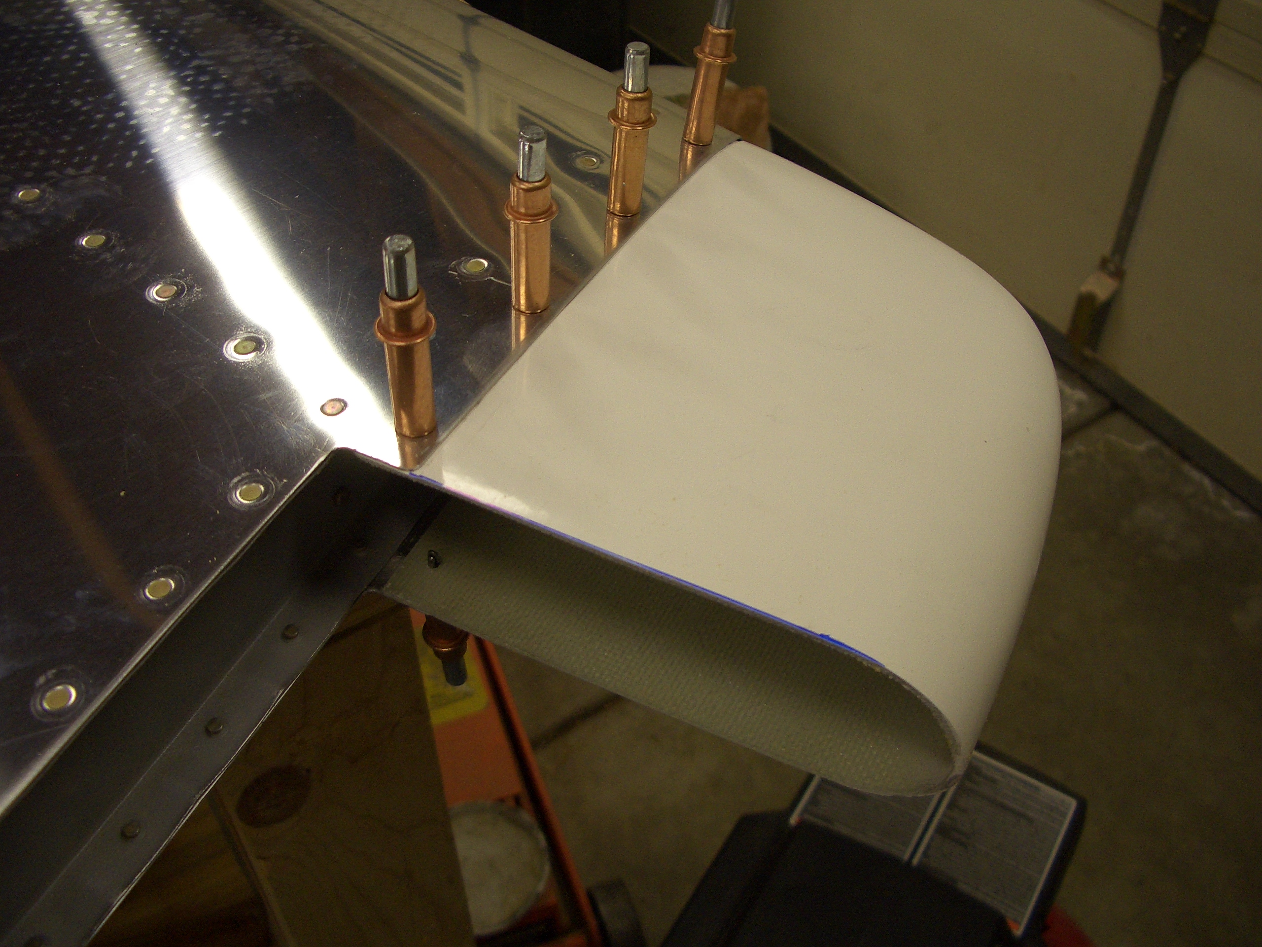
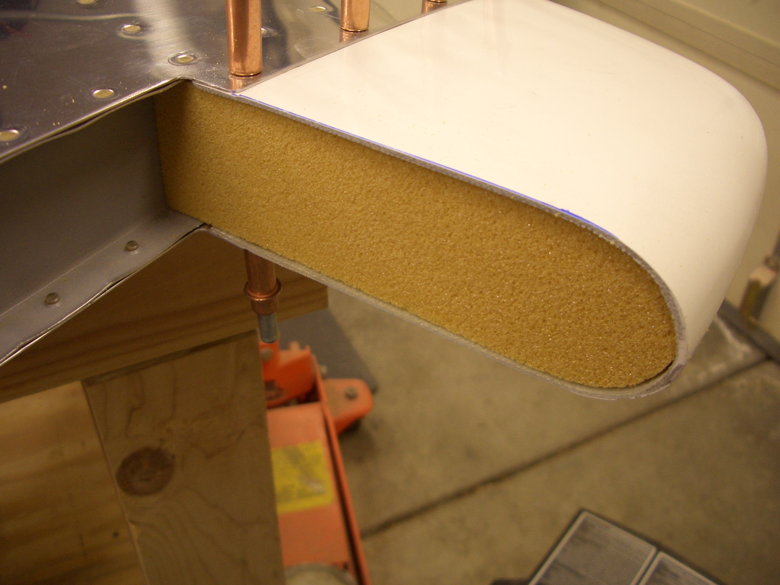
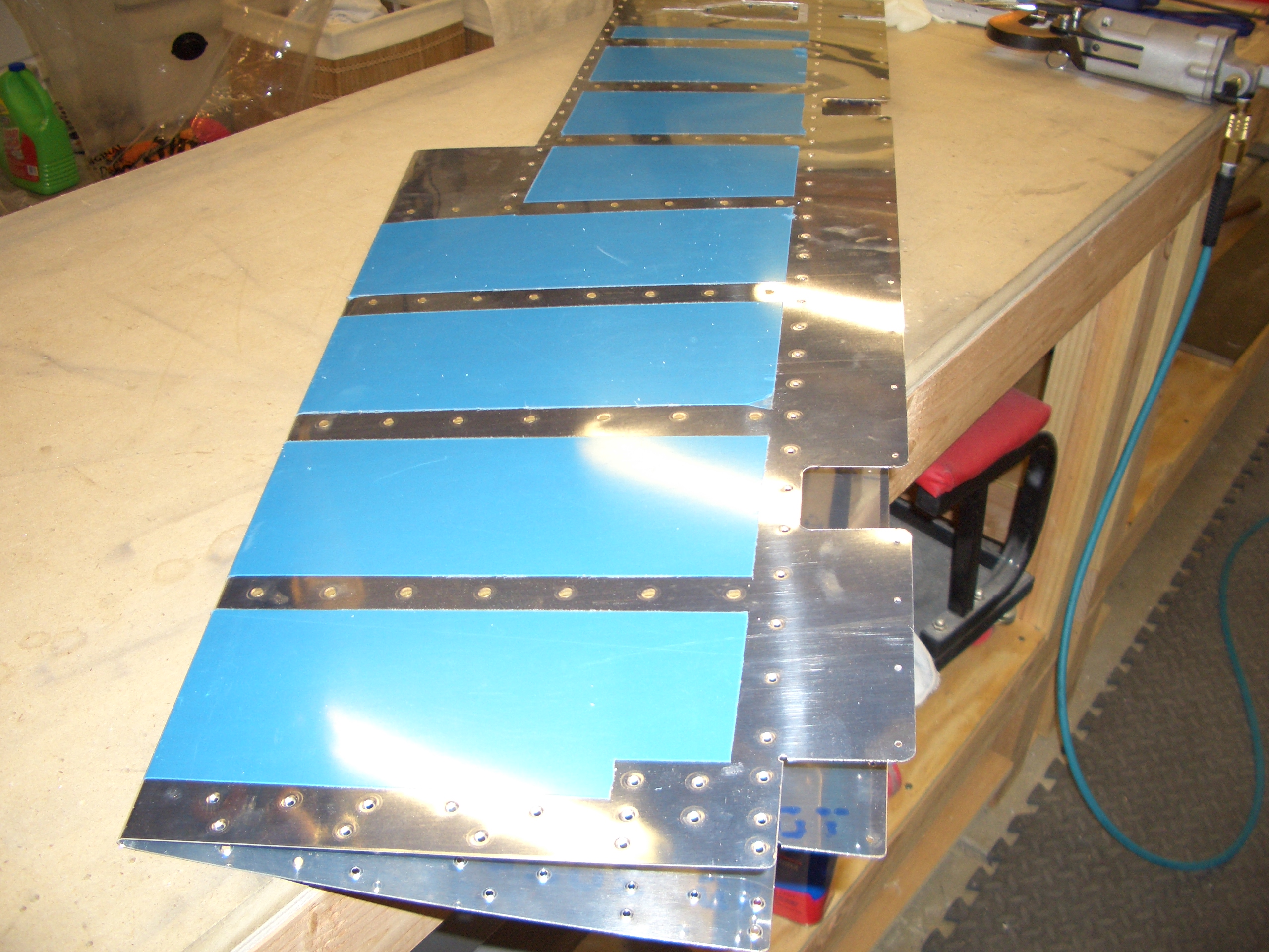
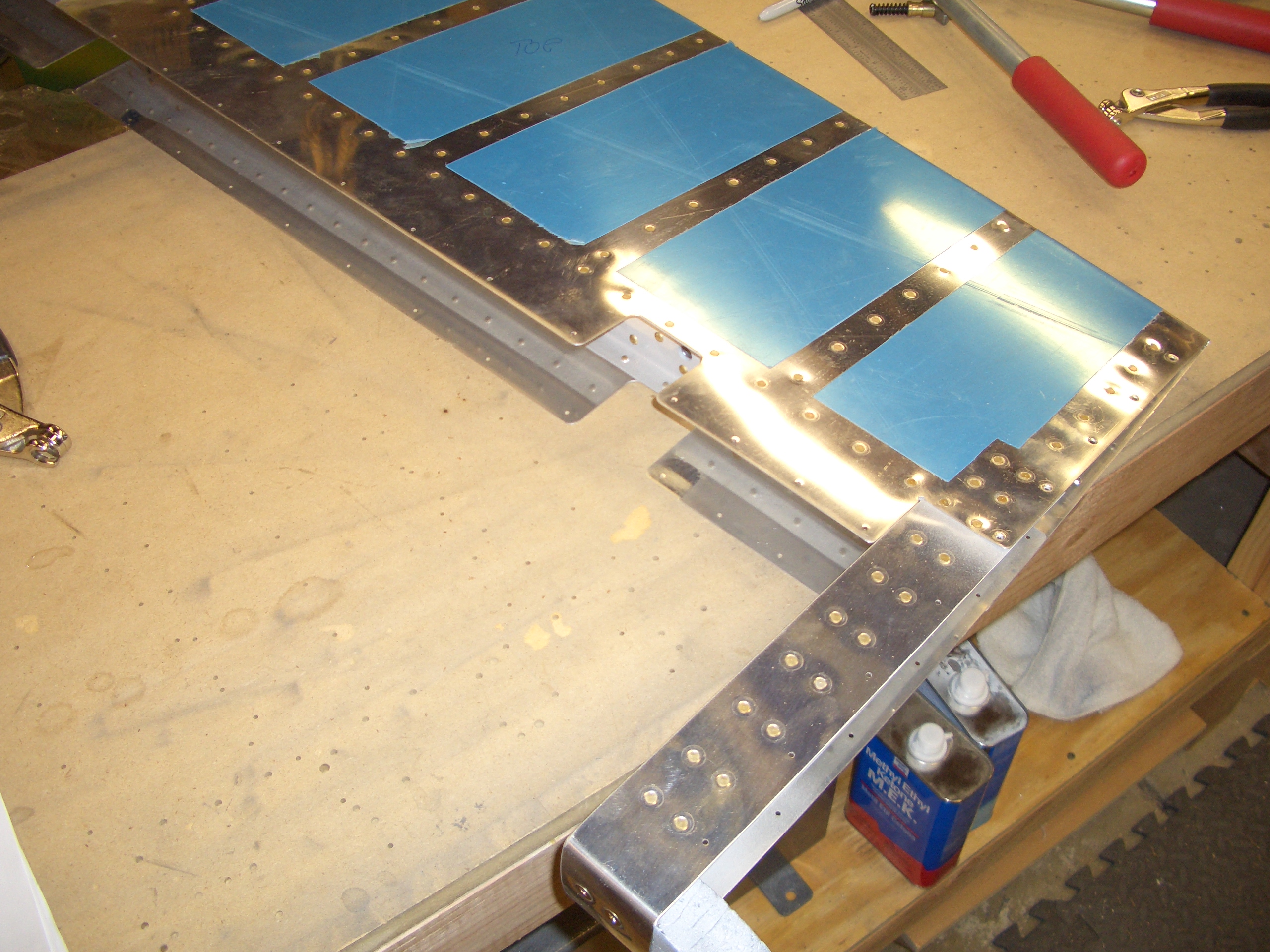
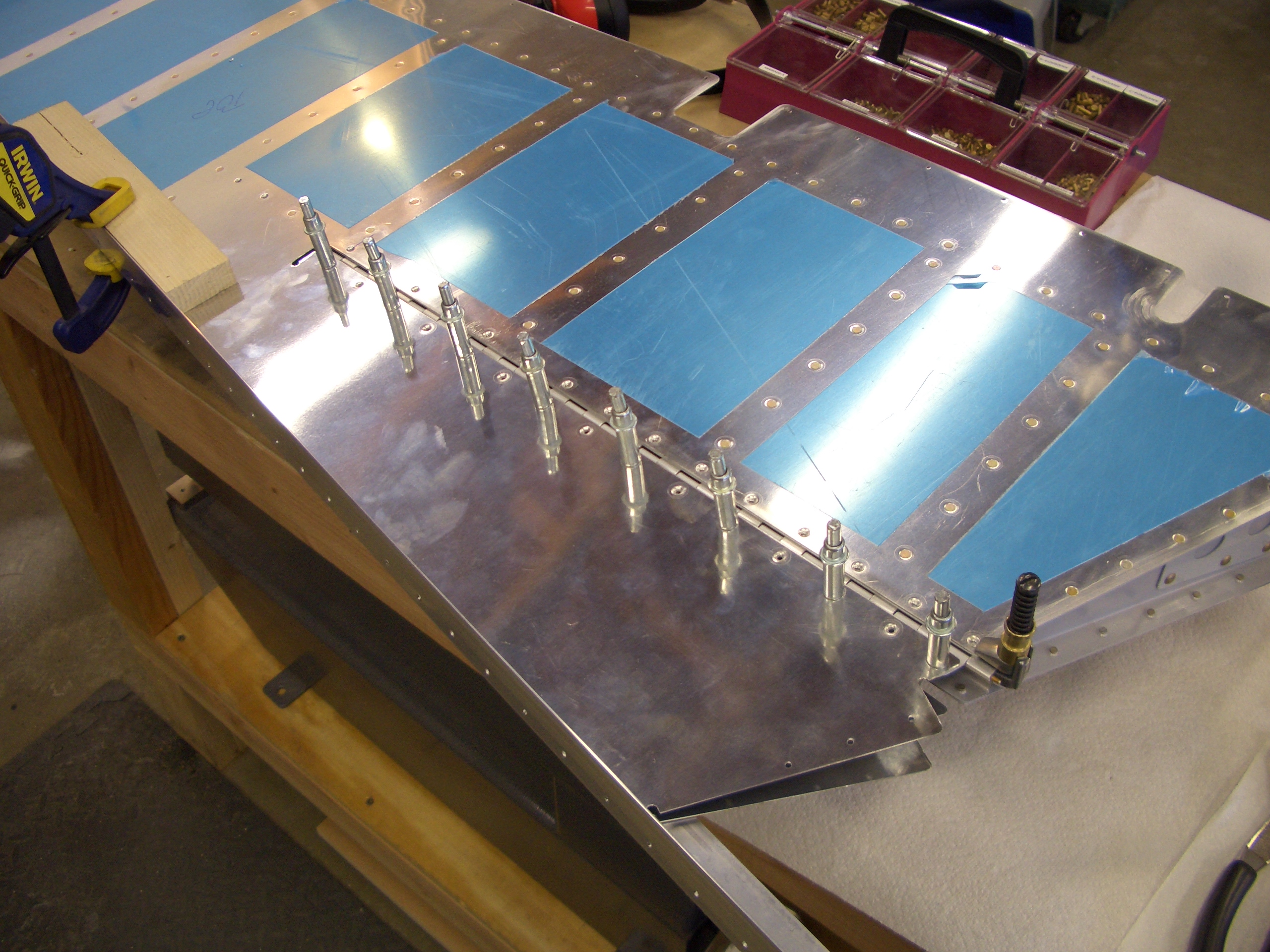
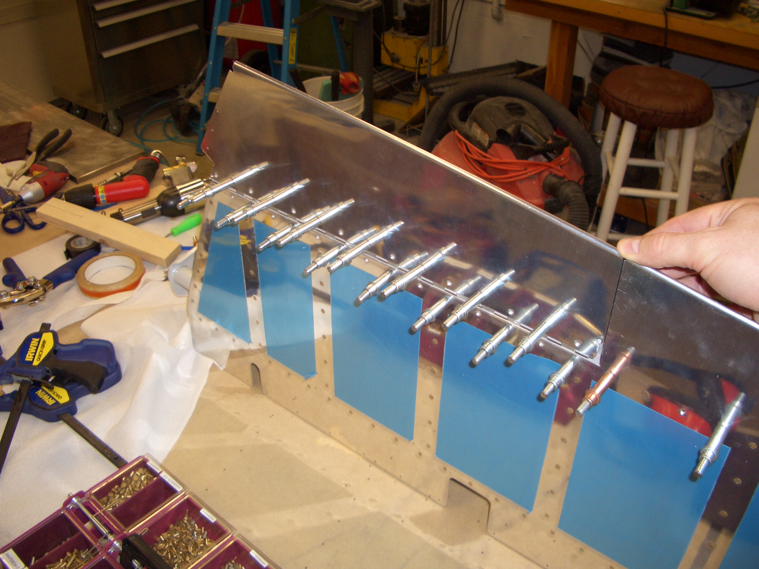
I clecoed the top of the trim tab to the bottom of the elevator to mark where the cut line should be on the elevator skin.
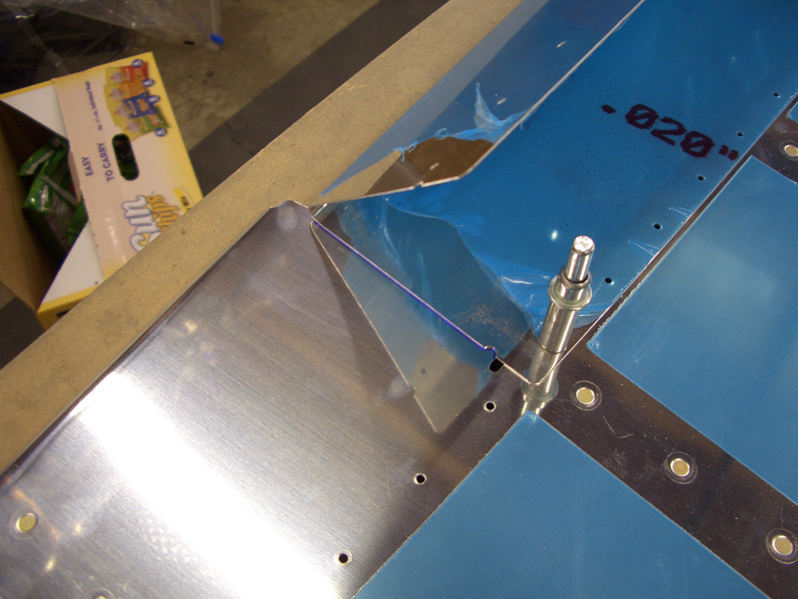
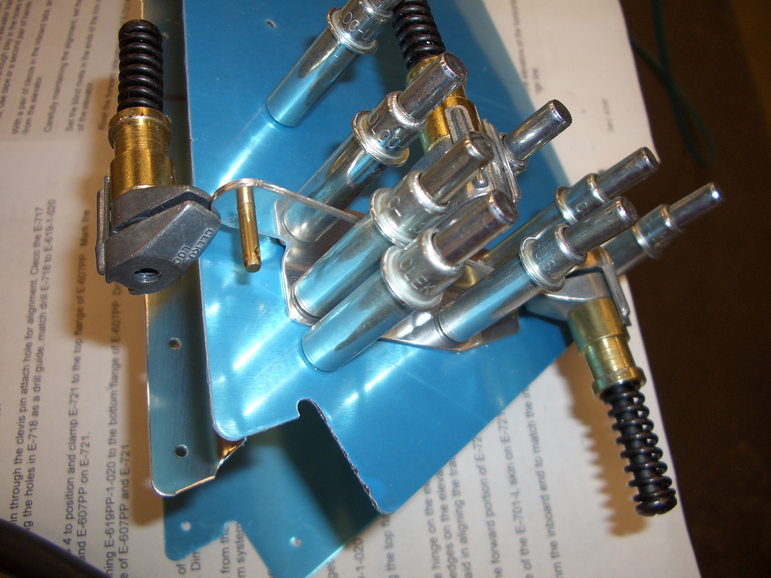
Then moved 3/32″ away (the minimum gap between the trim tab and elevator), and marked the elevator skin. You can see that I stuck a couple of extra rivets loosely in the holes for the trim spar to ensure these lines stayed perpendicular to it.