Prepped Elevator Skins for Riveting

I back-riveted the trim access reinforcement plate to the left elevator skin.


I also prepped the trim cover plate and attached it with AN507-6R6 screws.


Finally, I deburred, dimpled and put rivets in all of the skin holes where they are riveted to the stiffeners.  It’s too late to rivet these tonight, but I can knock these out quickly tomorrow morning.


Here’s the left elevator skin ready for back riveting the stiffeners.

Finished Rudder

My buddy Andre stopped by tonight to help me rivet the trailing edge.  It turned out great.


Here you can see that it’s completely straight.  One of the things Van’s really cautions you about is that setting these rivets can cause a hook in the trailing edge.  Using the sealant helps ensure this won’t happen.  I did get some very slight puckering between the rivets, probably due to slightly overdriving them.


We also got the leading edge rolled and riveted.  This was probably by far the hardest part of the rudder.  Despite how thin the skins are, these things are a bitch to roll.


I also got the rudder hinges installed.  Van’s uses rod end bearings for hinges on the elevator and rudders.  These are just screwed in to a specified distance from the spar web (or reinforcing plate in this photo).

Riveted Elevator Stiffeners

Since I couldn’t rivet last night because of the noise, I got up early and riveted the elevator stiffeners on before work this morning.  Here’s the left elevator.


And here’s the right.  Near the trailing edge, it was difficult to get the skin bent out of the way enough and still keep everything flat on the back rivet plate.  I ended up having to drill out a couple of rivets that didn’t end up flush with the skin.

Bent Elevator Trailing Edges

I fabricated a simple bending brake out of a 2×8 and a bunch of hinges.  I’ve heard other builders complain that they didn’t get a crisp bend between hinges, so I went a little overboard on the hinges.  They were on sale for 96¢, so it didn’t cost much.


After reading the experiences of others on vansairforce.net, I put the trailing edge up against the hinges and bent the skins basically flat (until the stiffeners were touching the opposite skins).  They spring back to roughly where they will sit once the spar is attached.  You have to put a surprising amount of force on this.  I basically climbed up on top of it and bounced (and I weigh 230lbs).  The whole process for both skins only took about 5 minutes.


Here’s what you’re looking for.  The skin stays flat right up until the trailing edge radius.

Prepped Elevator Skeleton for Drilling

I clecoed the counterbalance rib to the end rib and attached both to the spar.  Getting the last holes in the spar flange to line up with the holes in the counterbalance rib was a real pain and required several iterations of adjusting the bend of the counterbalance rib flange for that last hole.


Here is the counterbalance skin clecoed on with the counterweight in place.  I drilled through the holes in the end for the counterbalance weight attach bolts.


Here is the elevator skin clecoed on.  This is the left elevator.


And this is the right elevator.


While I was at it, I clecoed the elevator horns on so that they could be drilled at the same time.

Drilled Elevator Skins

These pictures look the same as yesterday, but all of the holes have been drilled.  Here’s the left elevator.


And the right…


For a little diversion, I fit and drilled the elevator trim mounts to the trim cover plate.  Ignore the left/right measurements in the plans, just visually center the trim servo arm over the cutout and clamp it in place.

Misc Elevator Work

A few of the holes in the elevator spars have to be countersunk, but the spar flange is too close.  I took one of my extra countersink cages that I picked up on eBay and ground off part of the foot to allow it to get up close to the flange.


I didn’t like the idea of routing the trim servo wires through the hole on the left since the servo shaft (which is threaded) extends through this hole in the full nose-up trim condition.  I’d much rather avoid the potential for chafing and drill another hole.  Since there was already a lightening hole in the elevator horn, I just drilled a 3/8″ hole in the center of that.  I’ll put a snap bushing in that hole later.

Prepped Elevator Skeleton for Priming

I haven’t had much time to work on the plane the last few days because work’s heating up.  We’re working 7 days a week to get the new iPhone 3.0 software out the door.  I need a little break though, so I managed to get a few of the elevator parts ready for priming.  Here’s the counterweight skin.  I beveled the side and back edges where the main skin overlaps to prevent a bulge in the skin at this spot.


There’s not enough room between the trim spar flanges (partly visible in the upper left) to get a normal squeezer to dimple the rivet holes, so I tried the pop rivet dimple dies.  I only got one done before the nail broke (expected at some point).  The female portion of the die shot off with blinding speed and it took me about 5 minutes of searching the garage to find it.  I think I’ll look for another way to dimple these holes.

Primed Elevator Structure

The right elevator counterweight (shown here on the left) has to get trimmed because the right elevator is lighter (the left elevator contains the trim system, so the counterweight needs to be heaver to balance the left elevator.  Trimming this was a pain.  I tried the bandsaw, but the counterweight jammed in the blade (and bent the blade).  I also tried a hacksaw, grinder, chisel, and file.  Nothing worked great, but I eventually got all the metal removed.


Here are all of the parts cleaned and primed, ready to be assembled.  I have no idea why Van’s has you build the elevators separately.  It’s going so much faster to just build them at the same time.

Riveted Right Elevator

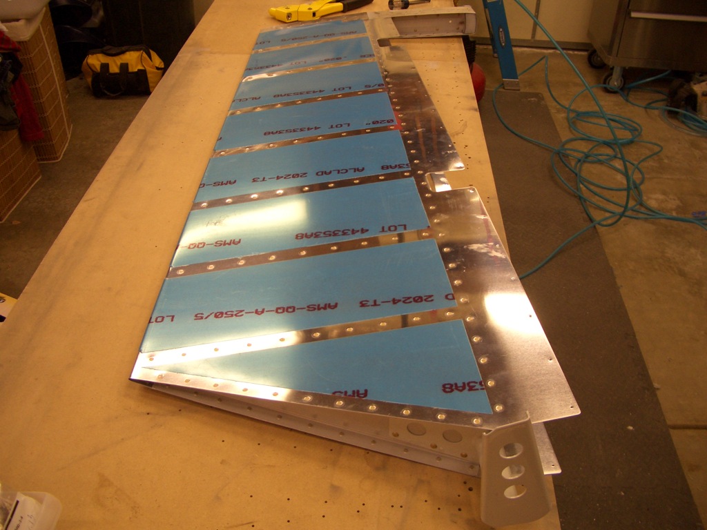
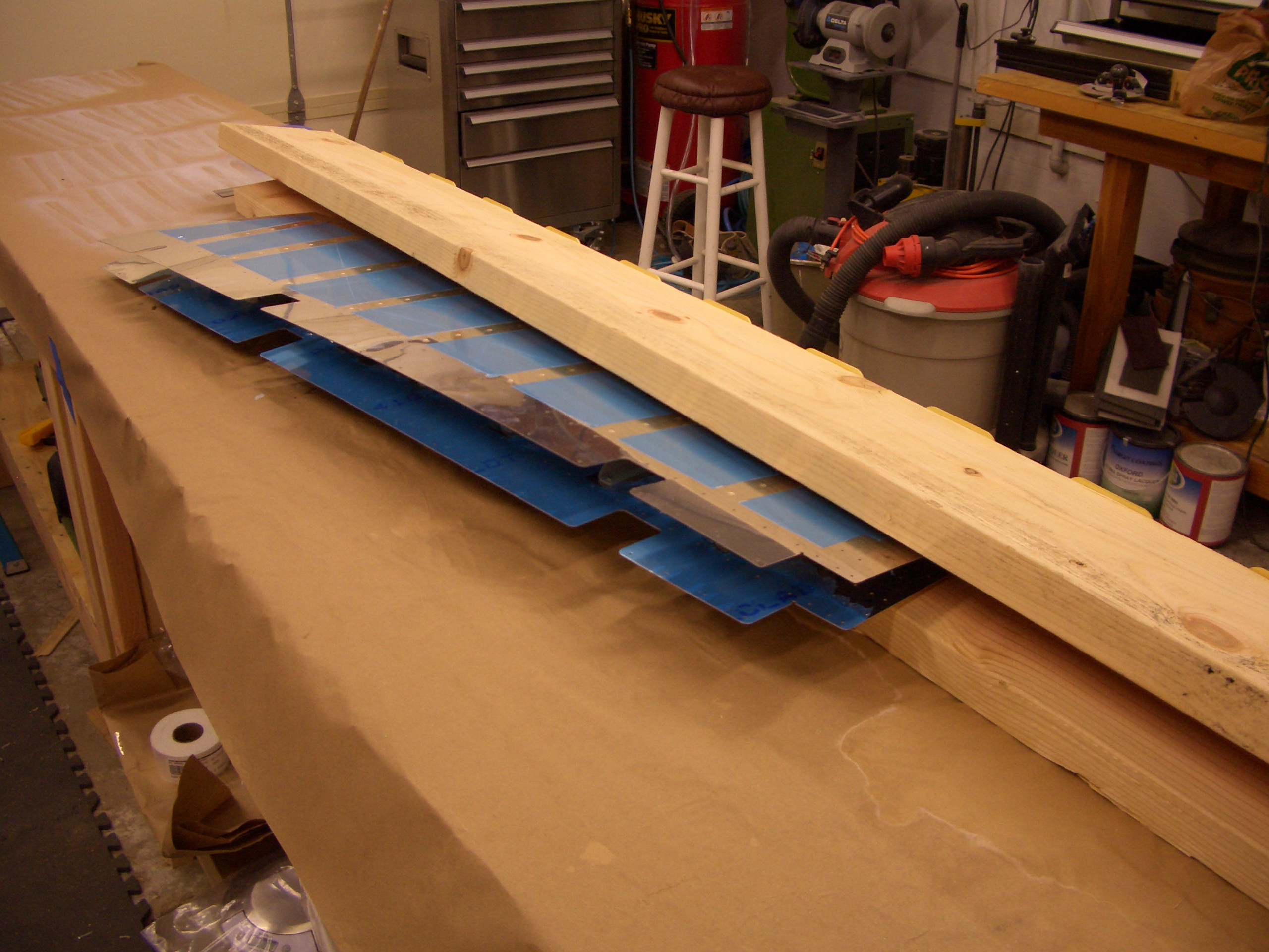
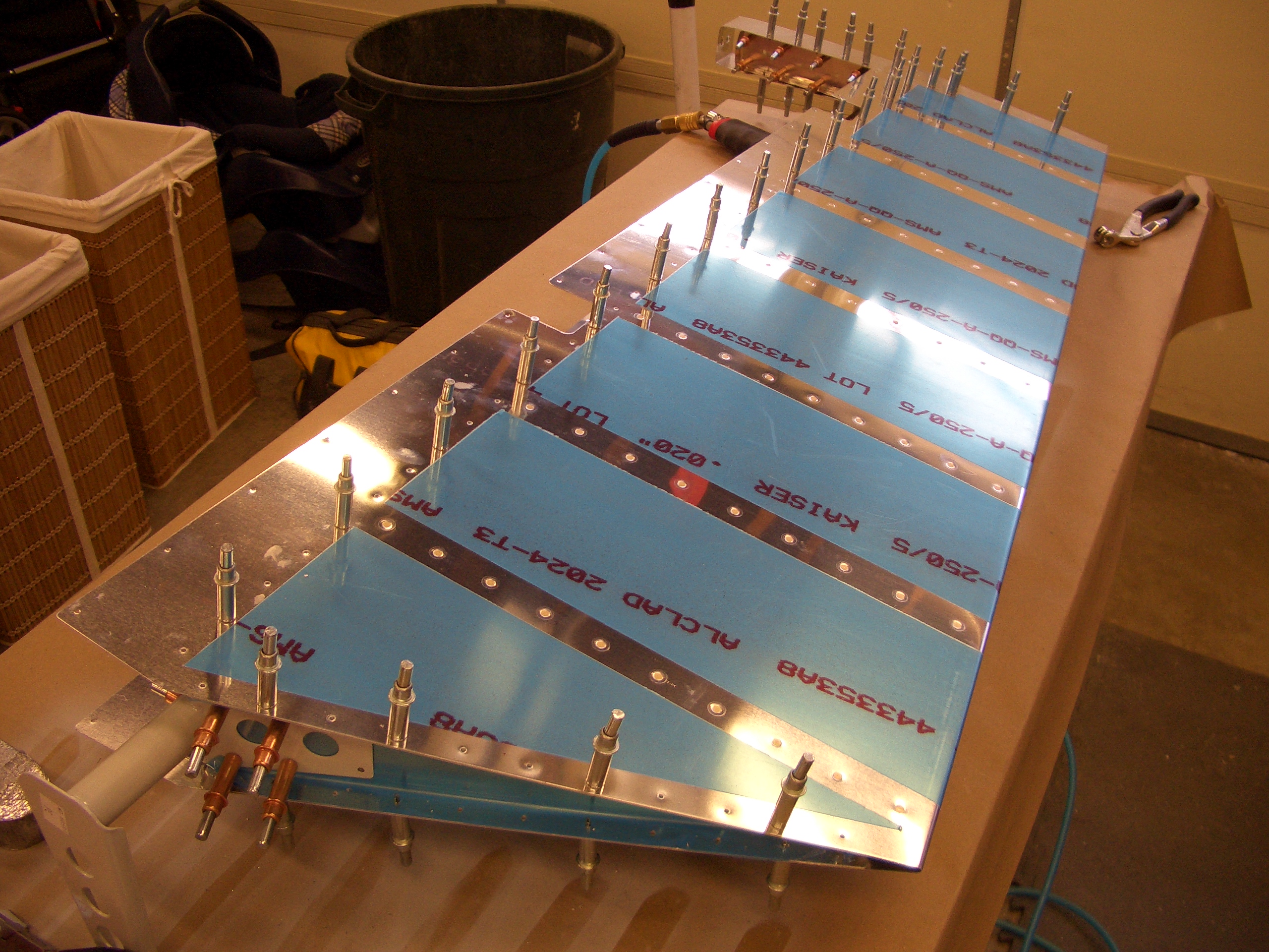
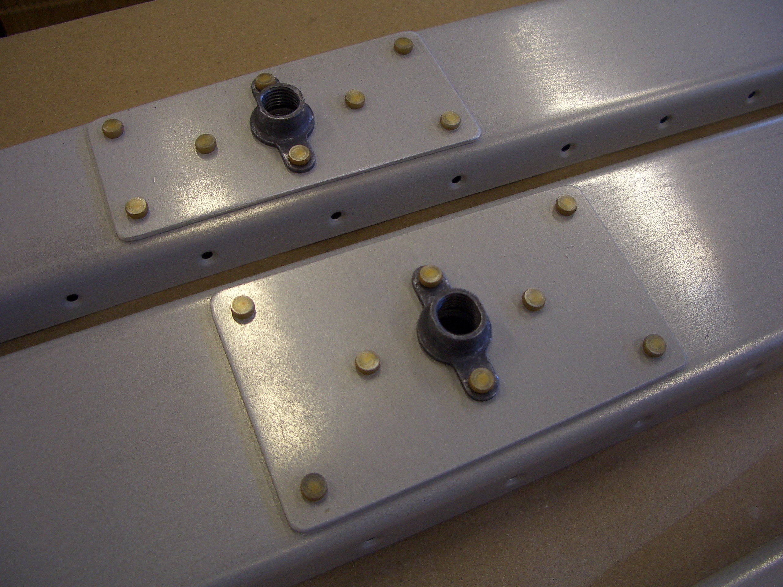
I started by riveting the hinge reinforcement plates and platenuts to the elevator spars.  I’m still working on both elevators to save time.


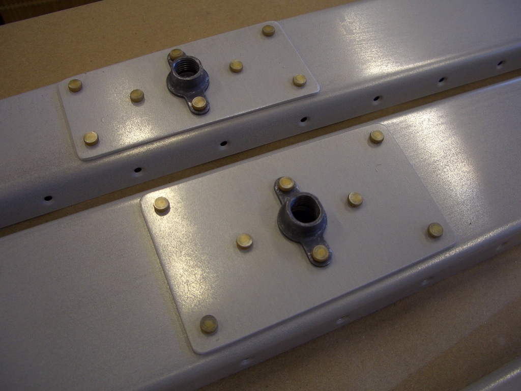
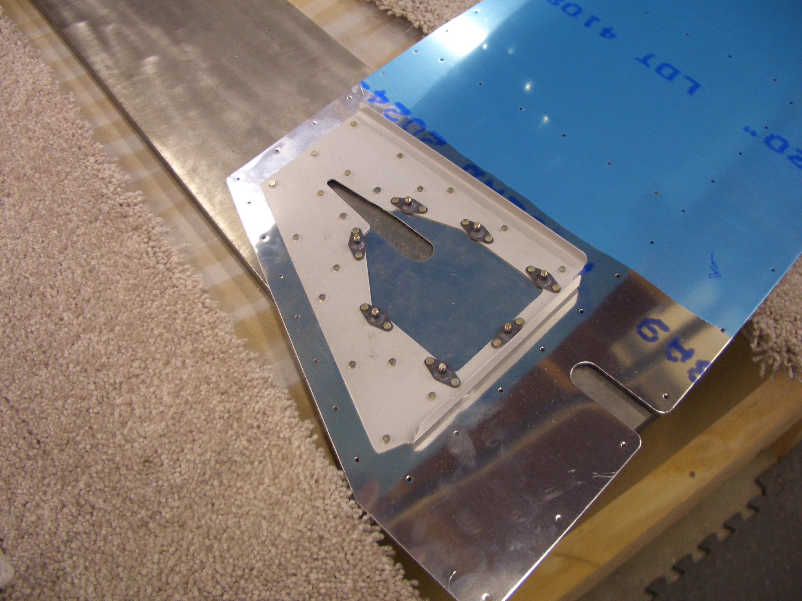
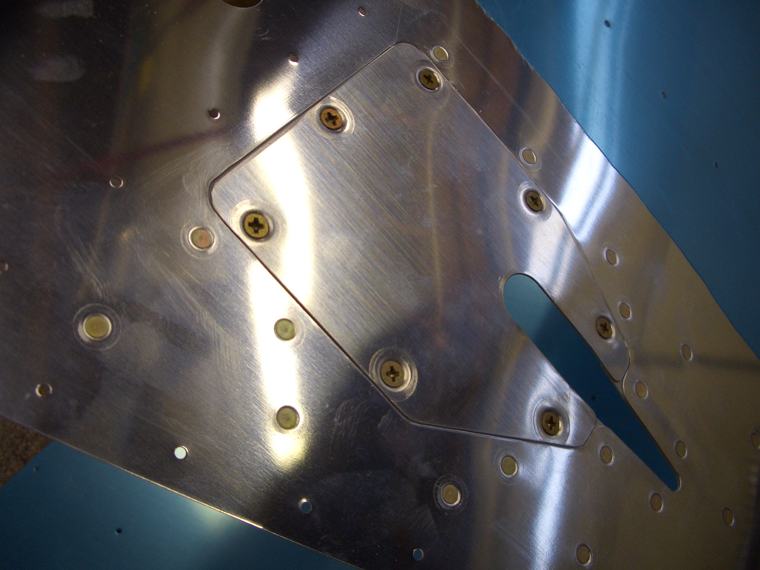
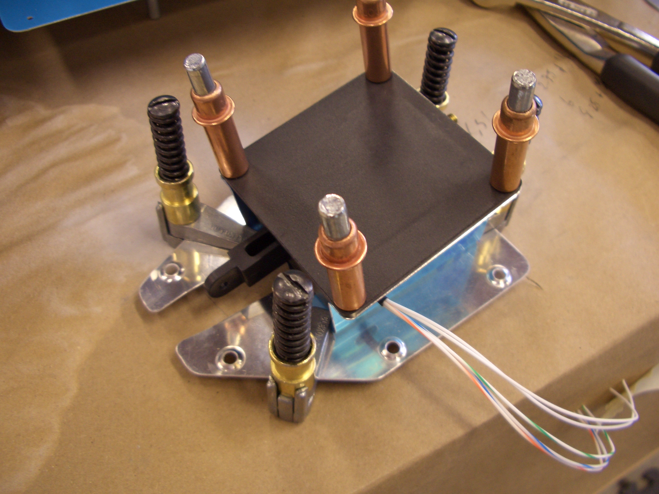
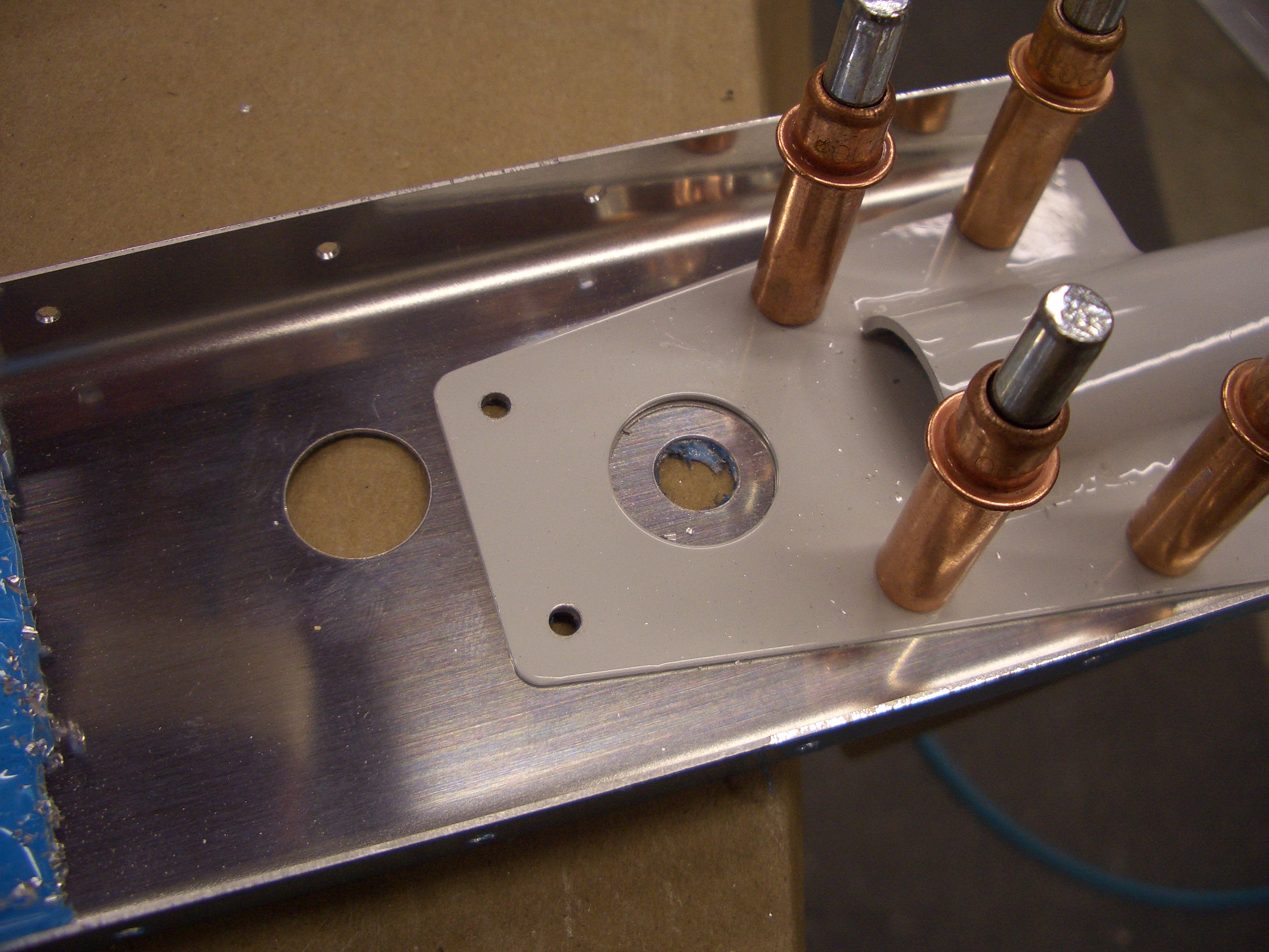
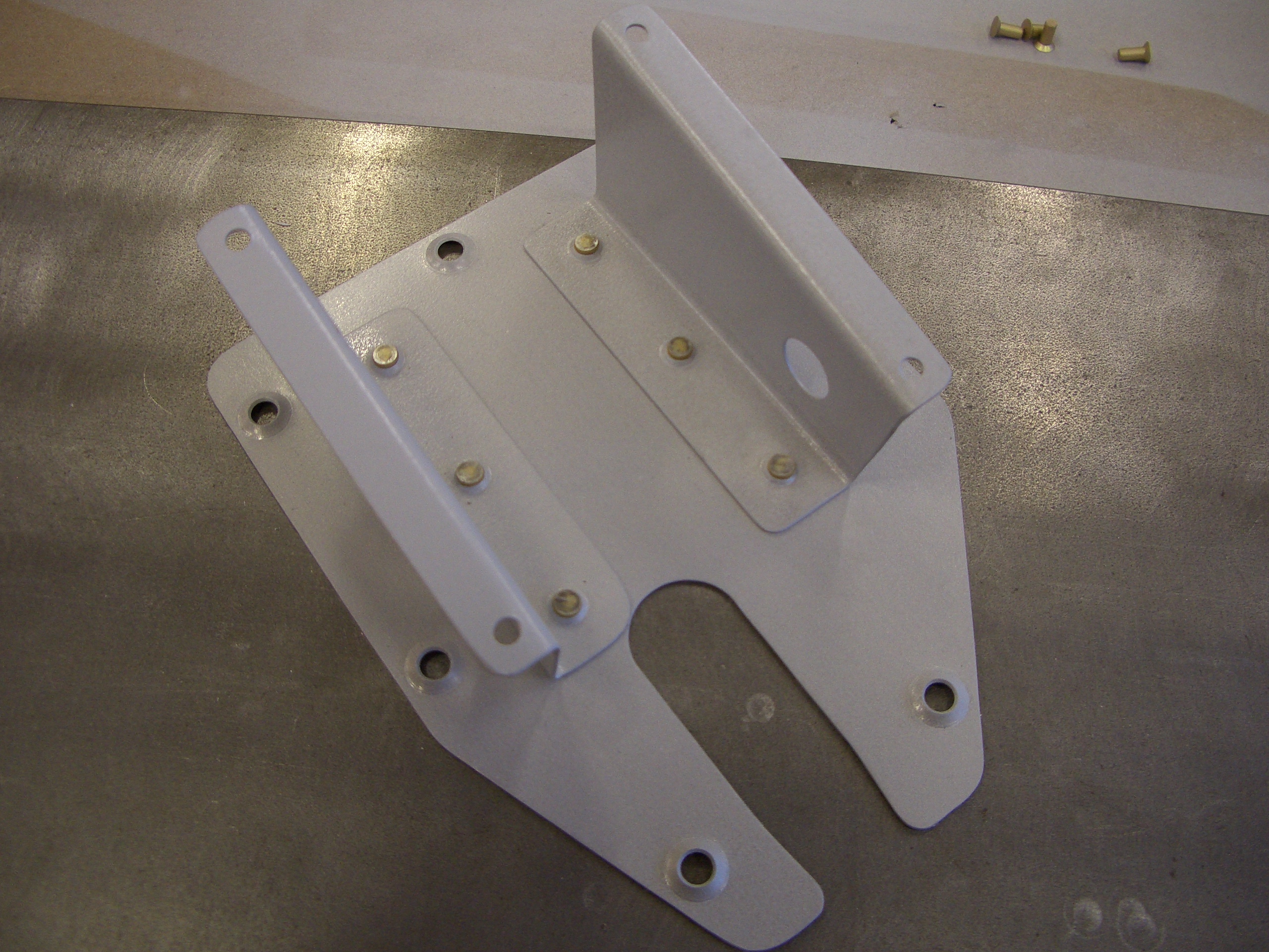
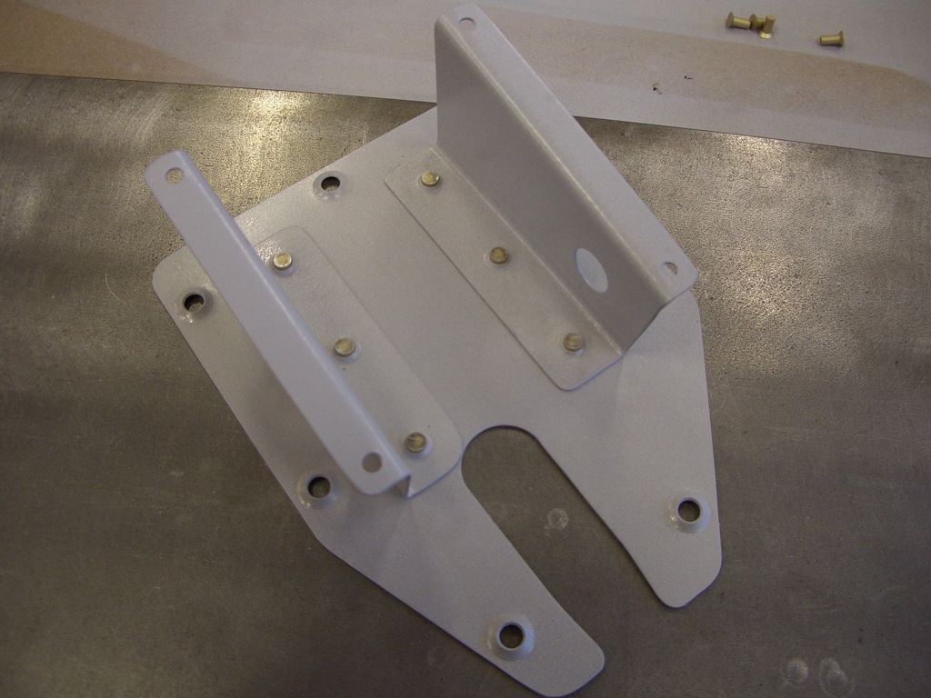
Here is the trim servo supports, back-riveted to the trim cover plate.


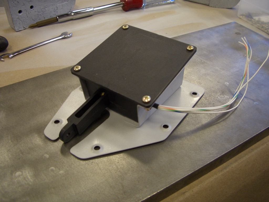
And here is the servo, mounted to the supports.


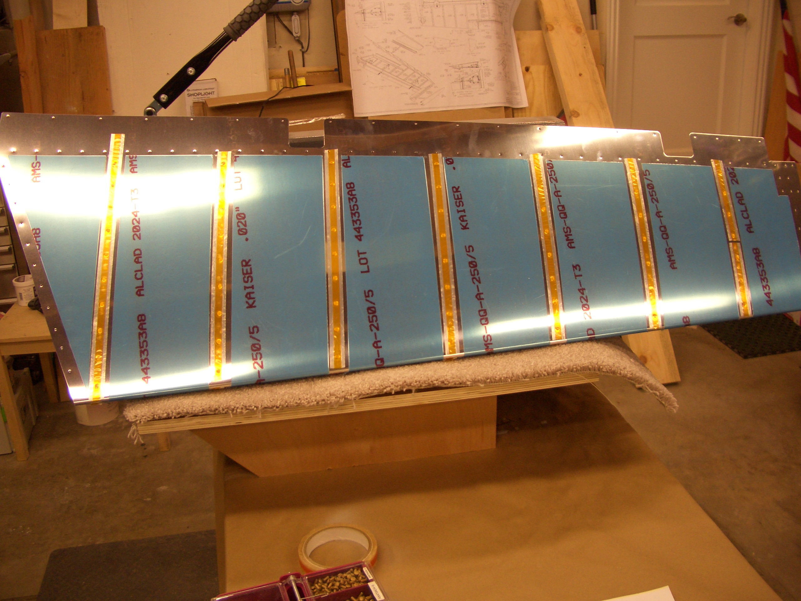
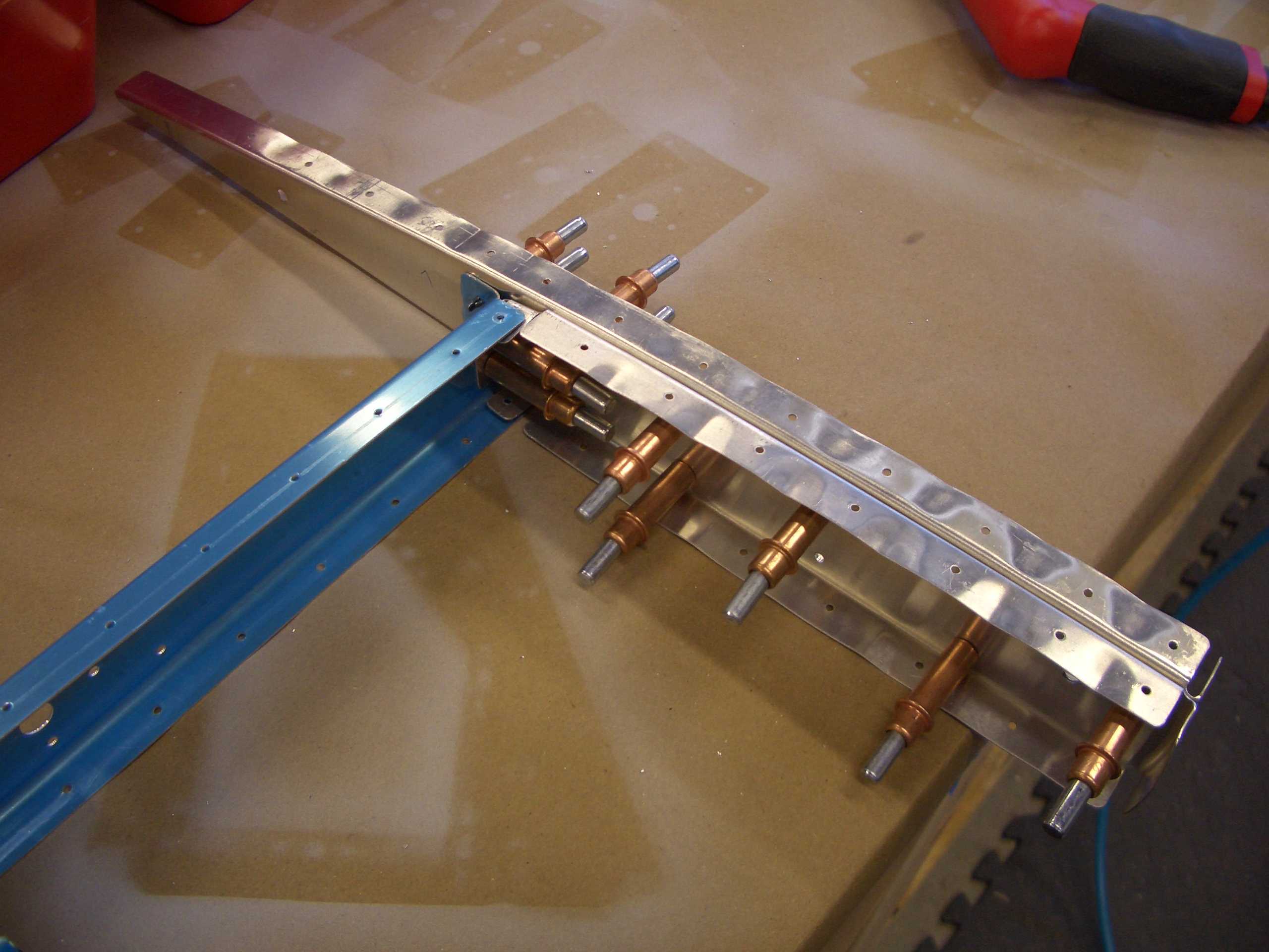
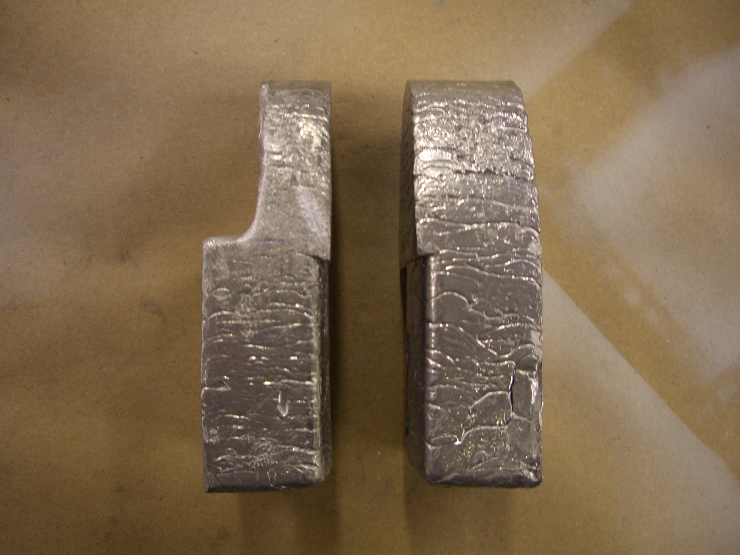
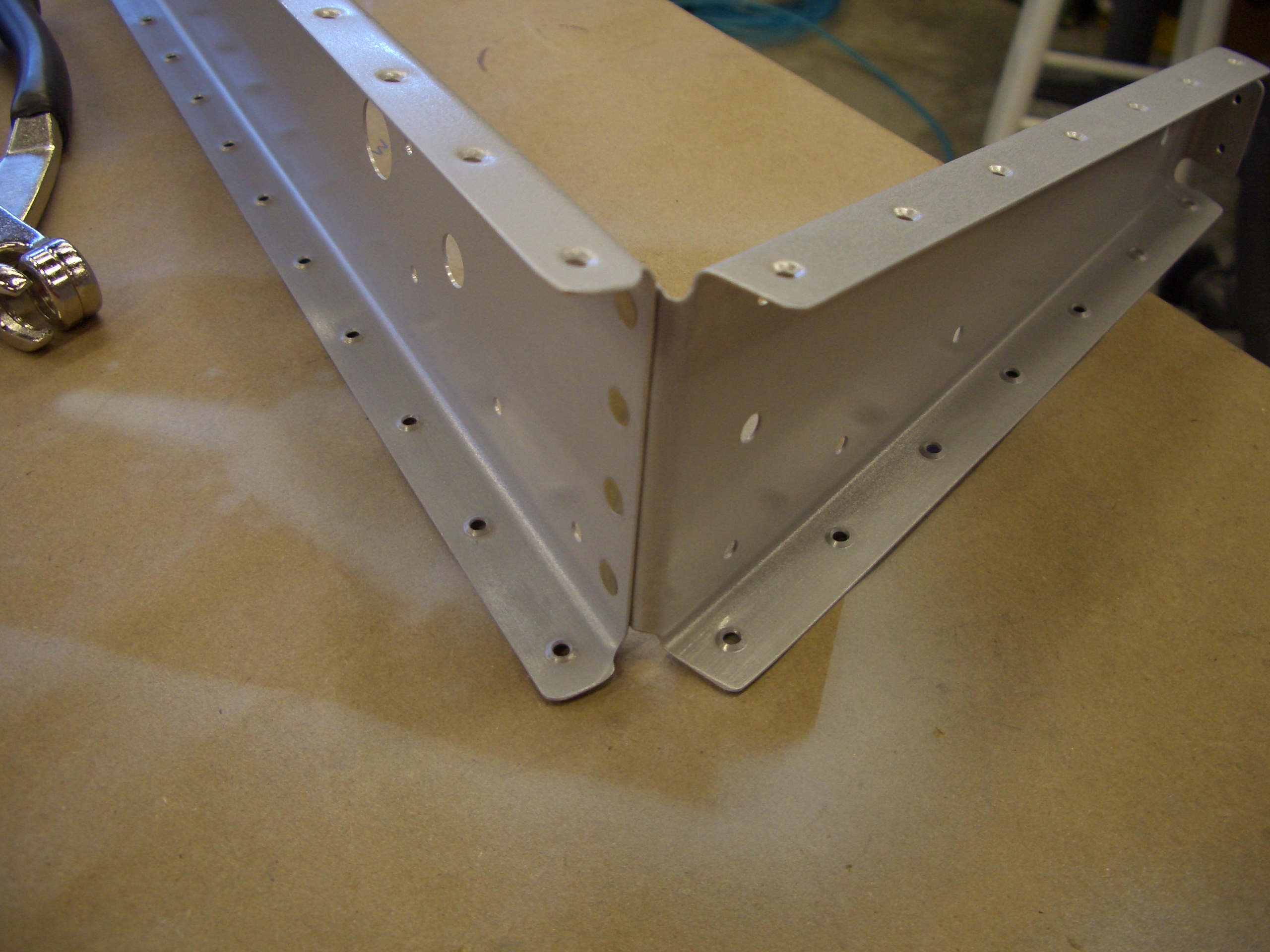
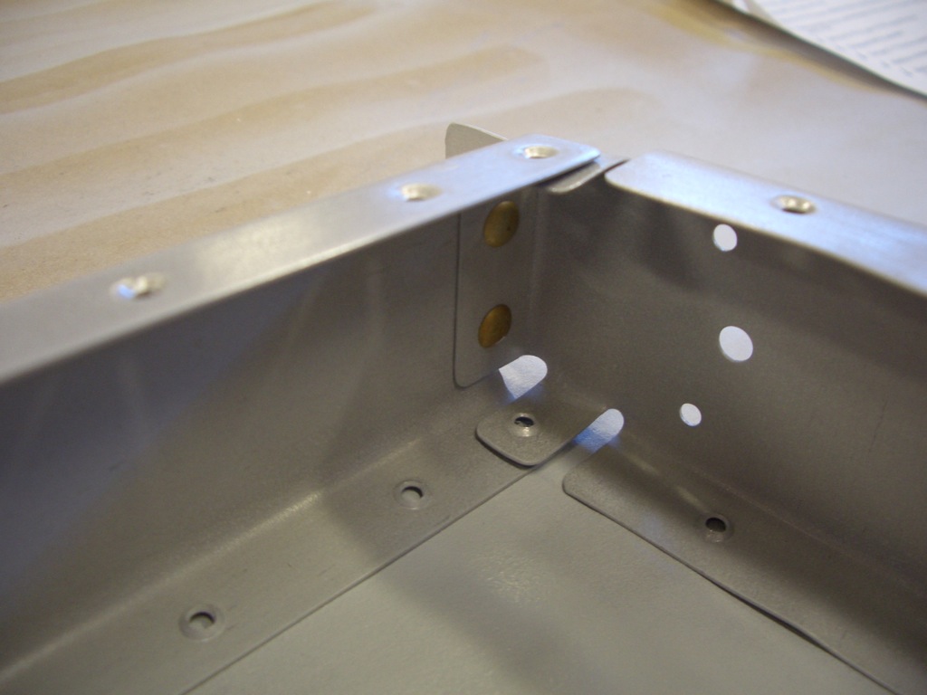
I riveted the root ribs onto the spars.  This is the root rib for the left elevator.  You can see it has a blunt end where the trim spar attaches.


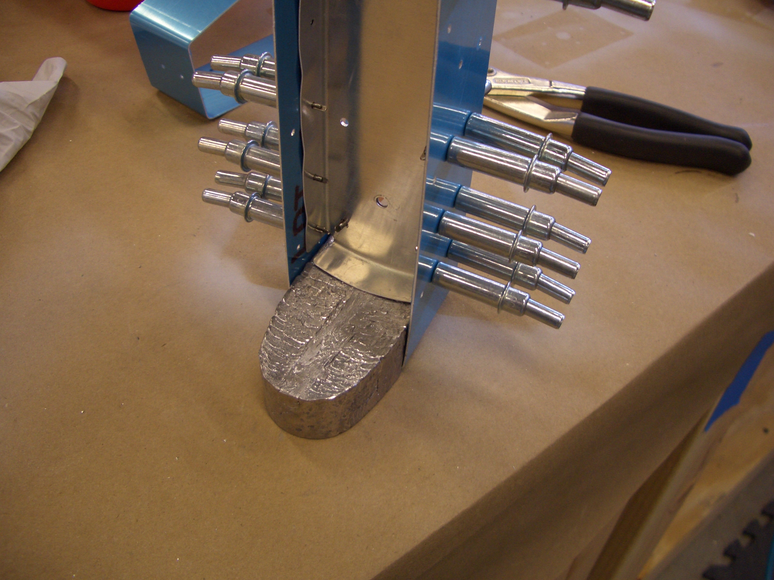
The instructions are definitely not in the best order here.  They have you rivet E-703 (end rib) to E-704 (counterbalance rib) before riveting them both to the spar.  The problem with that is that these rivets can’t be squeezed if you do that and must be shot/bucked (probably with a double offset set).  Instead, I squeezed these now while they’re easy to reach.


And then squeezed the rivets holding E-703 to E-704.


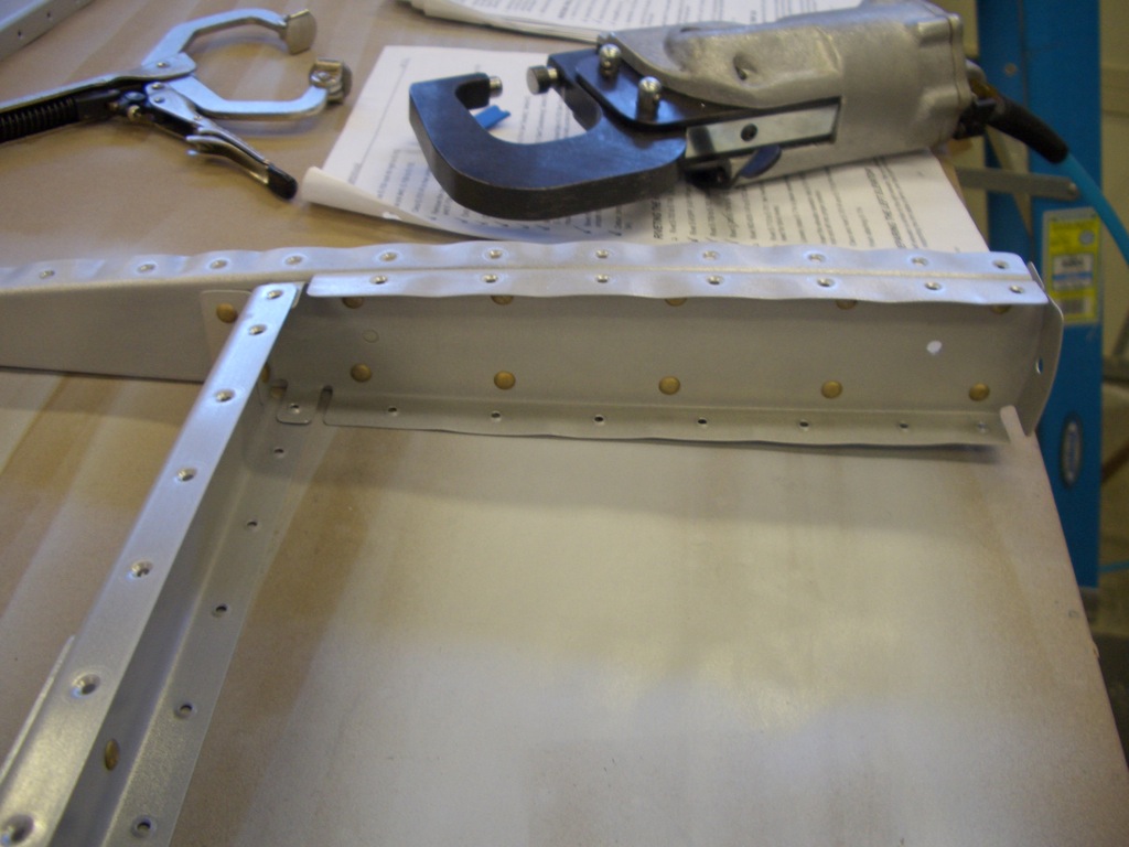
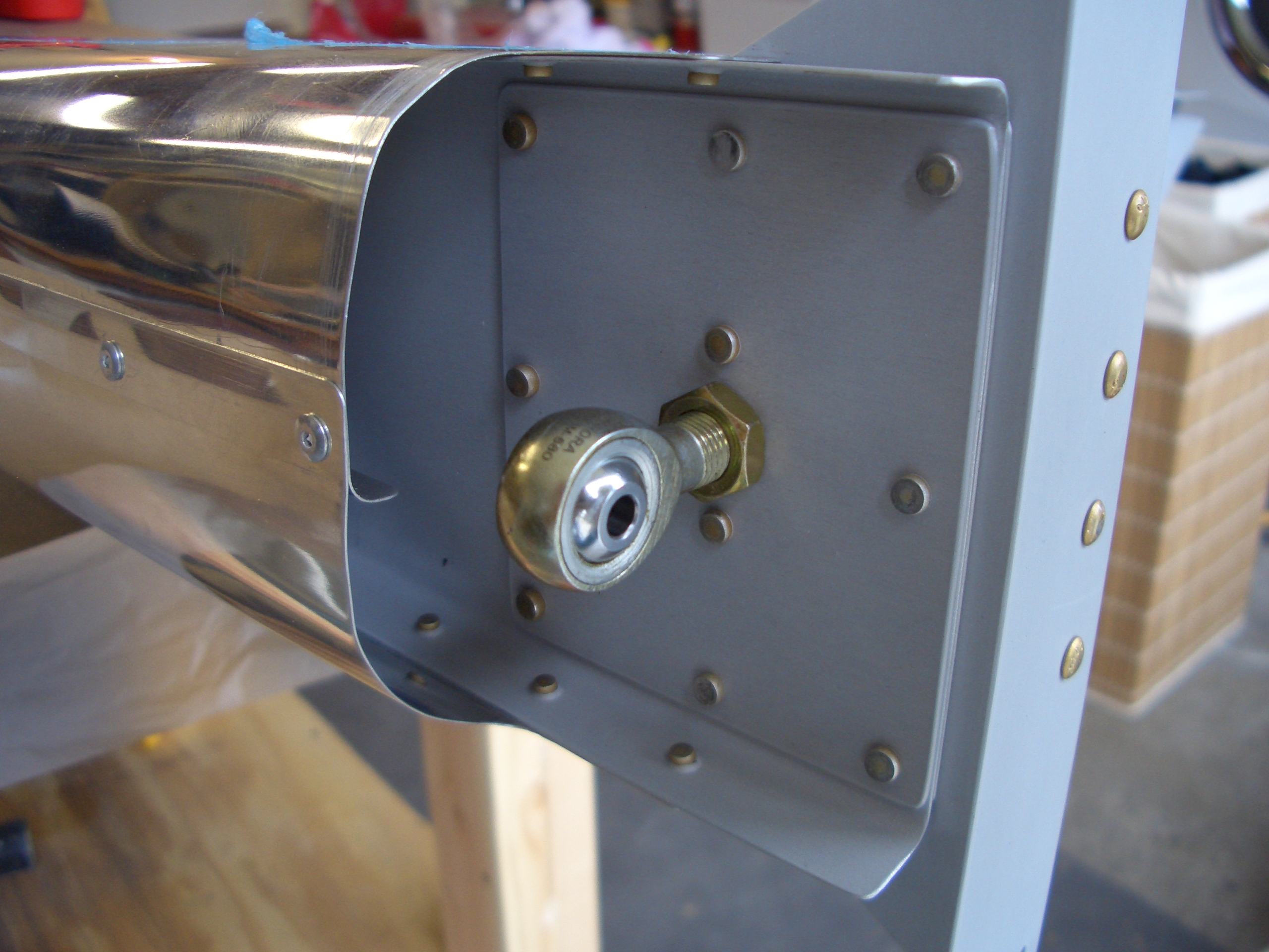
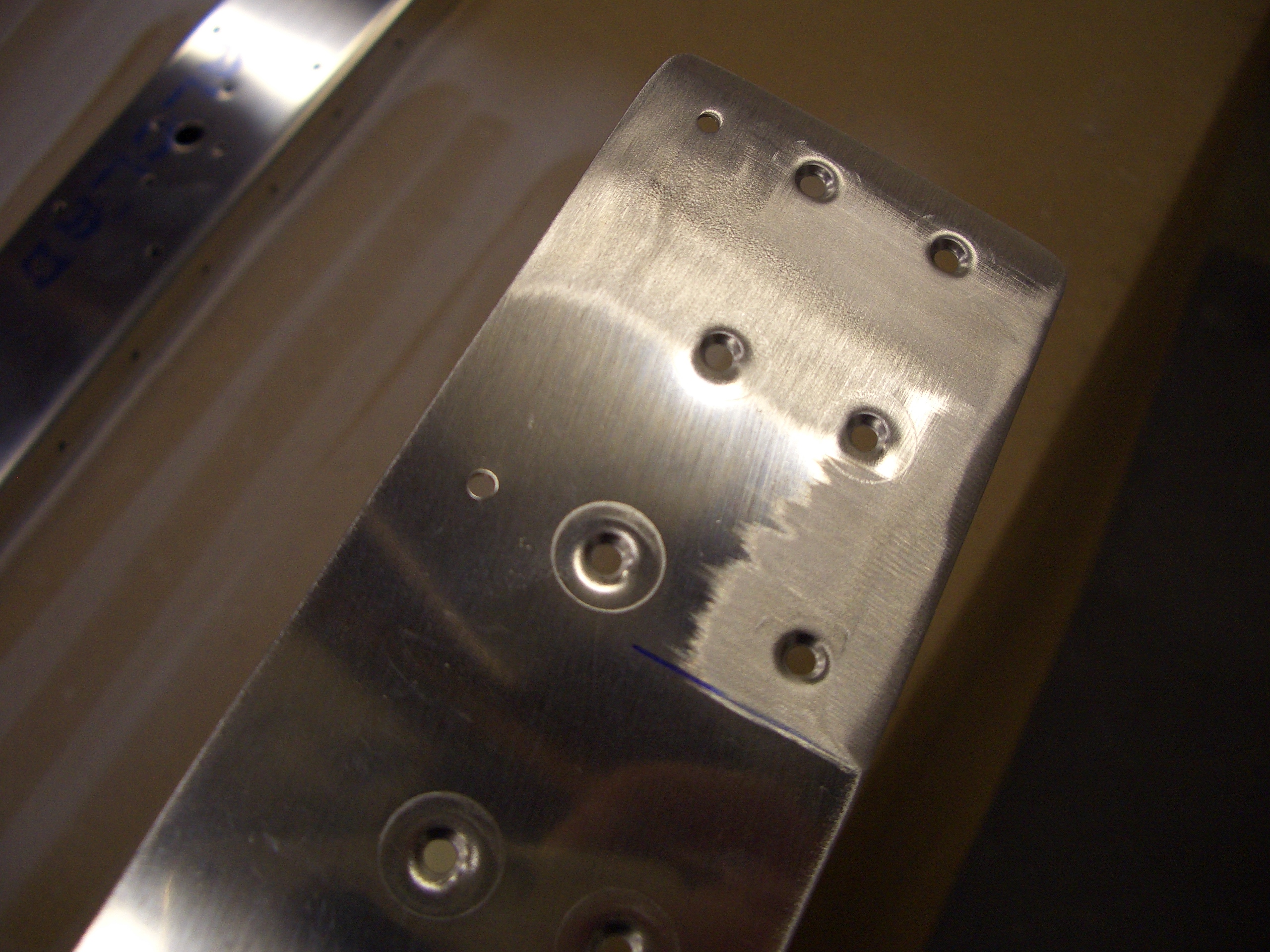
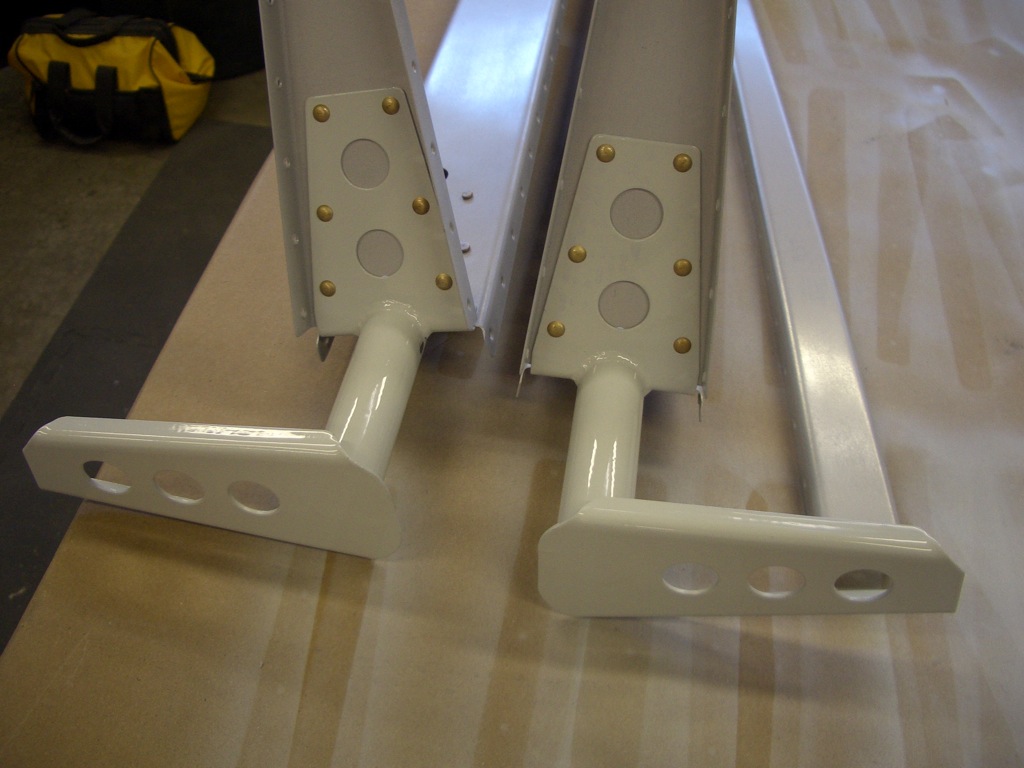
The elevator horns can now be riveted on.


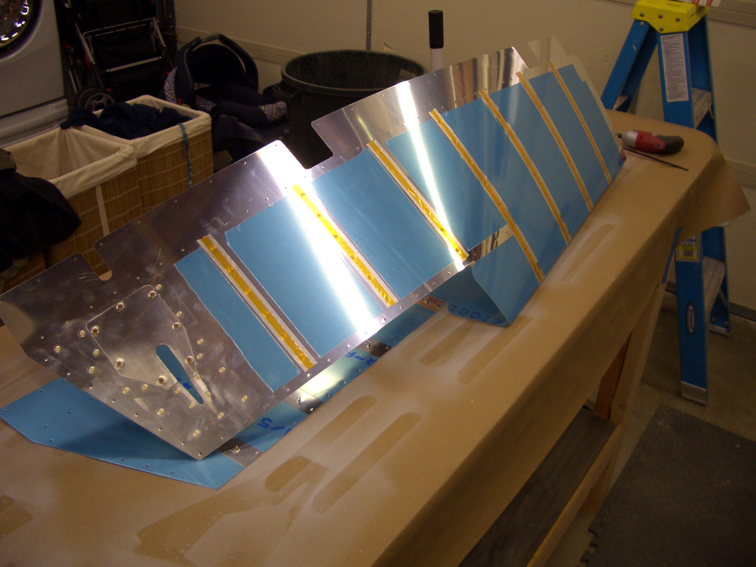
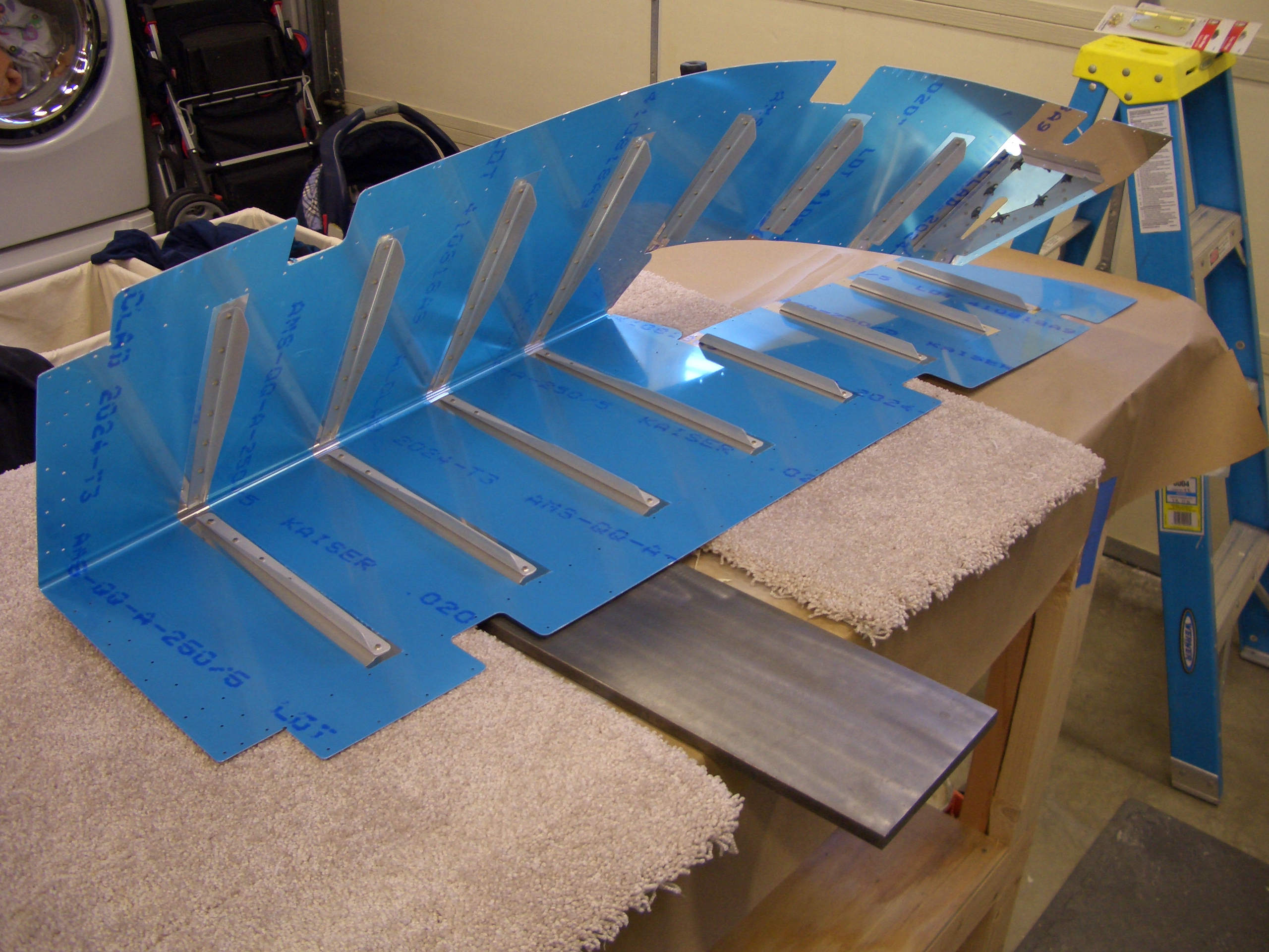
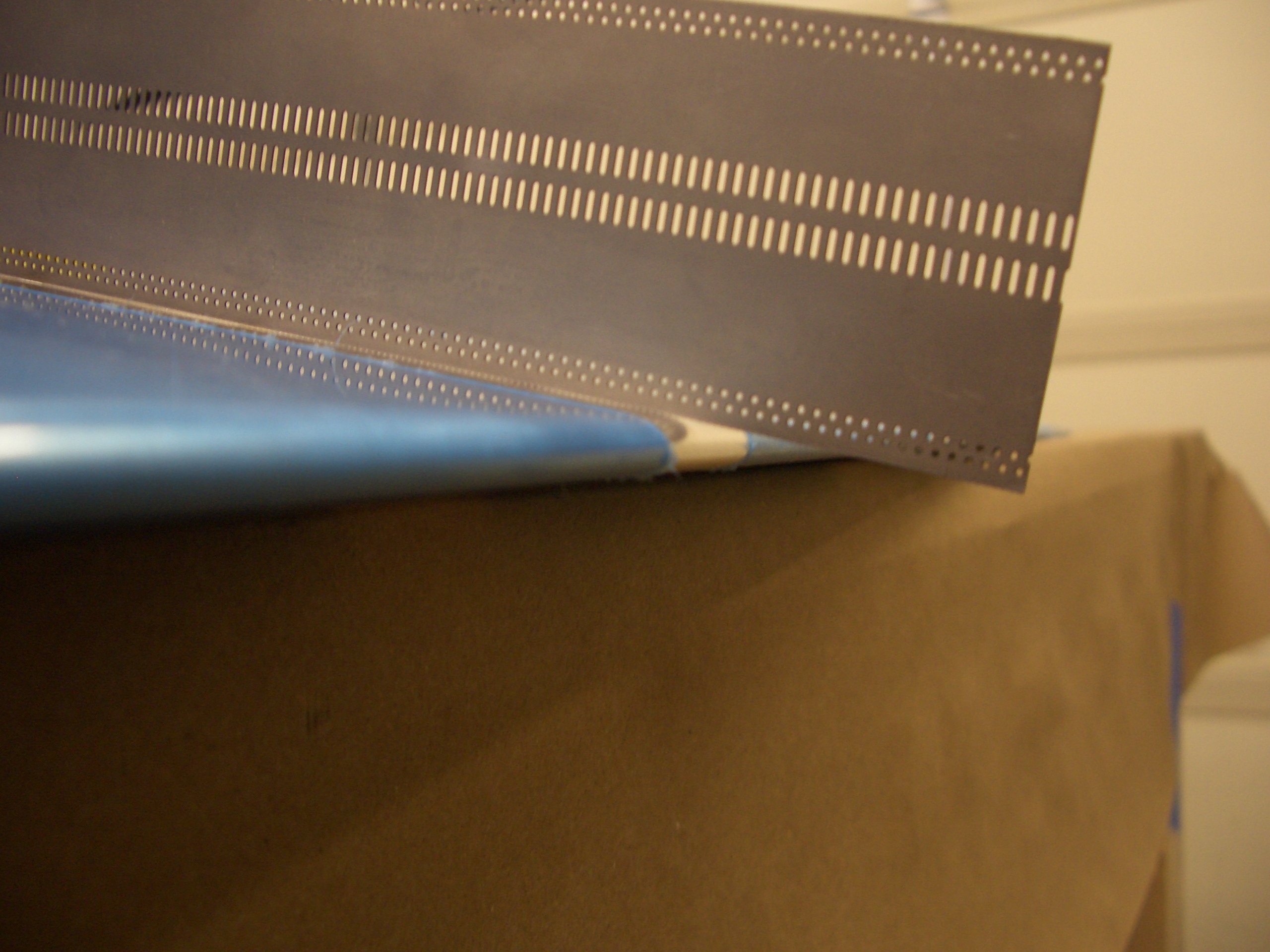
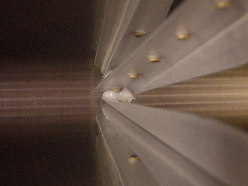
I added a dab of RTV to the back end of each stiffener pair to tie them together.  This helps prevent cracking here according to Van’s.

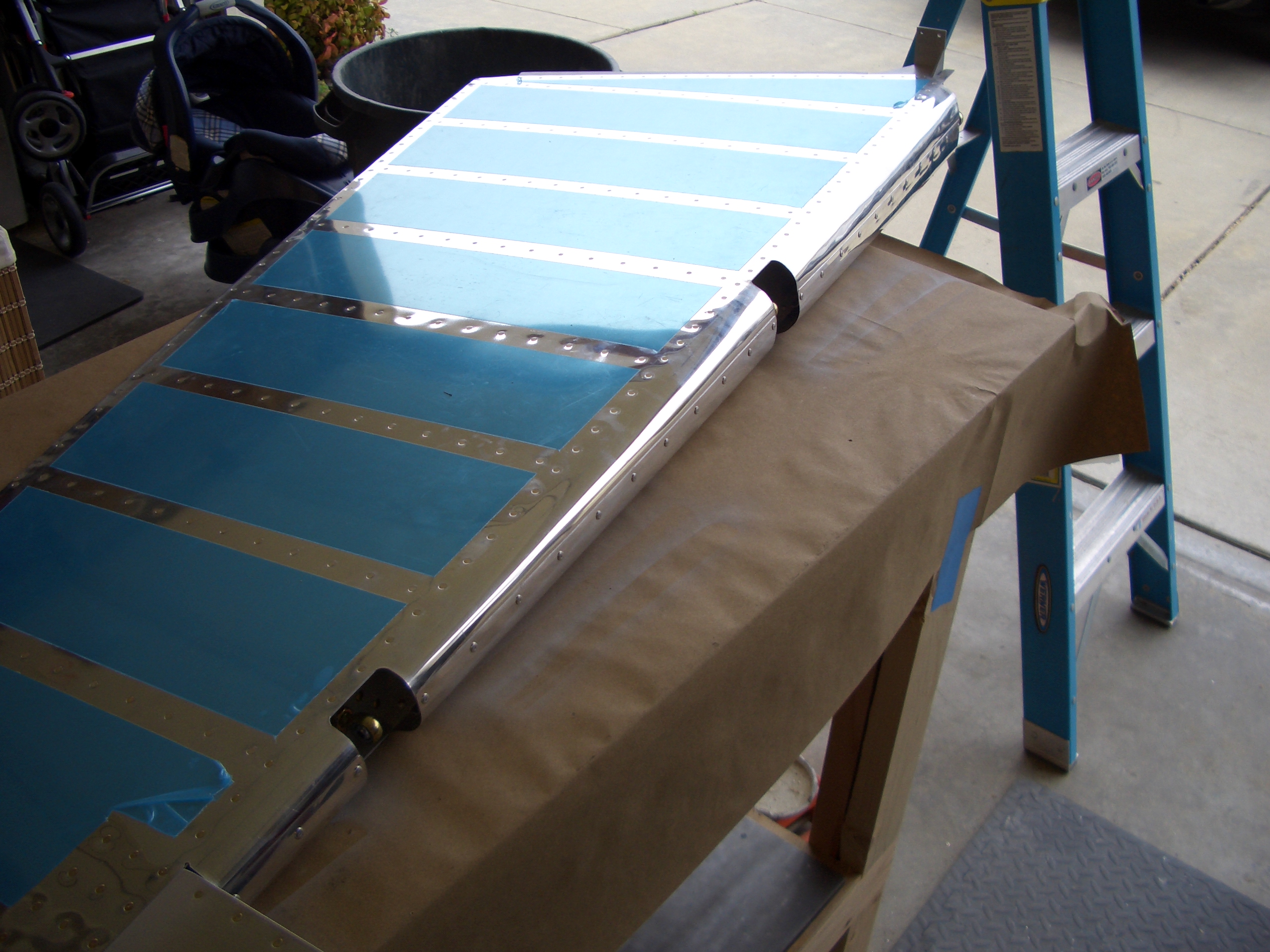
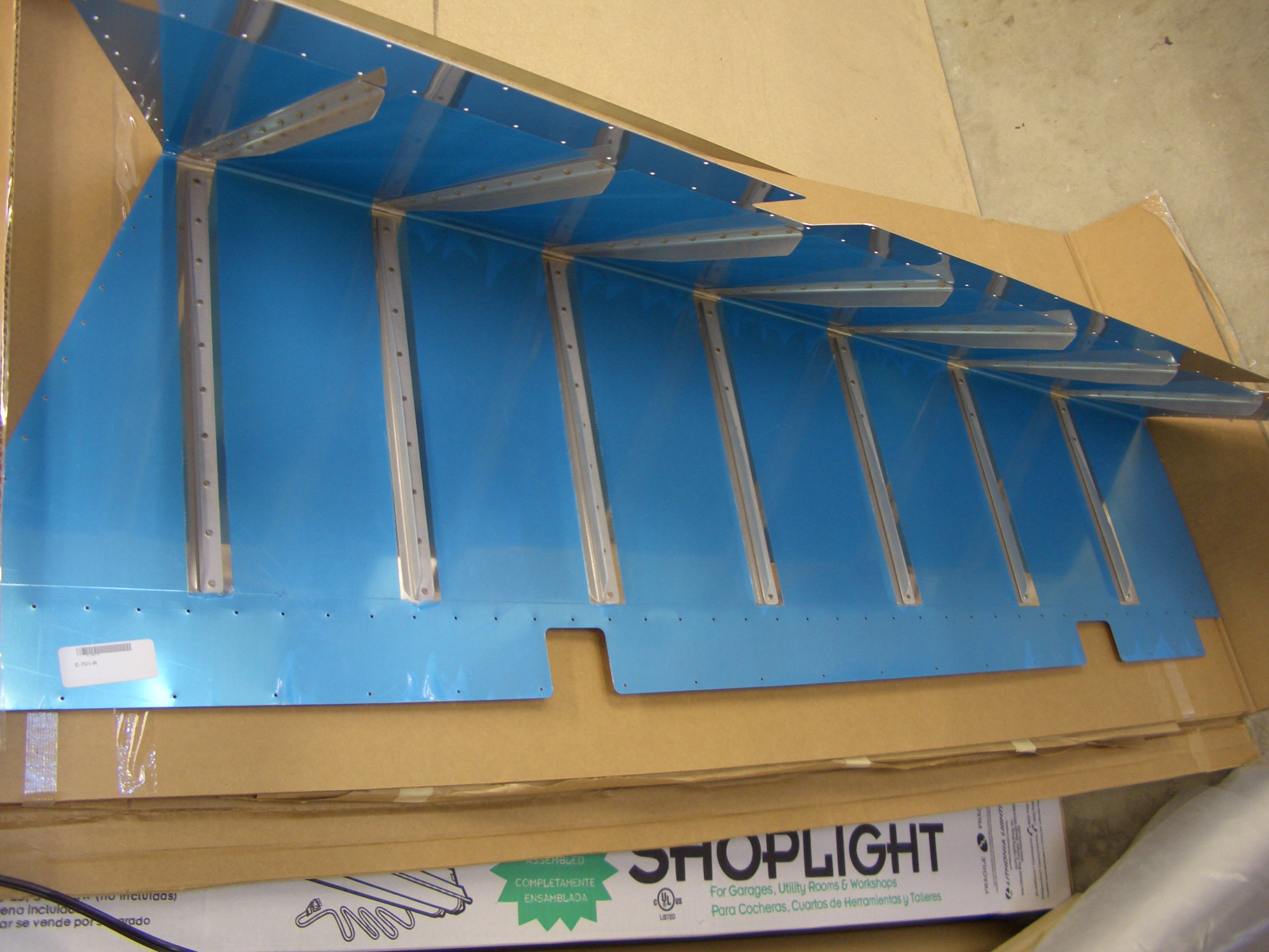
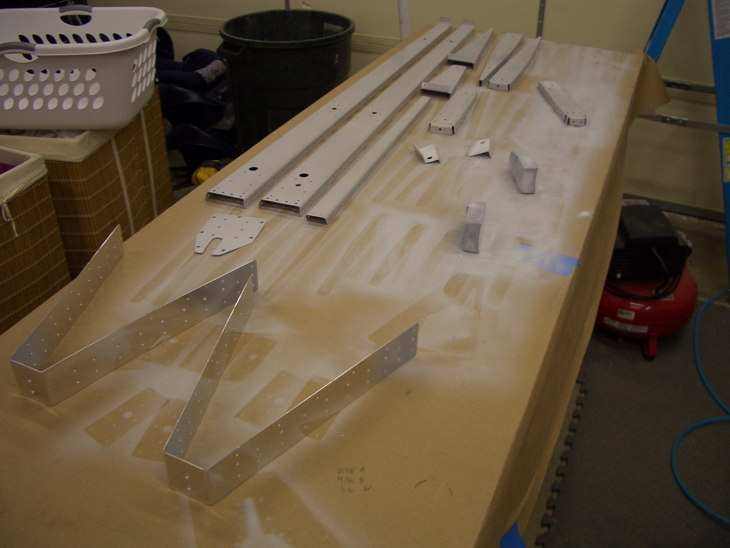
And the right elevator is complete except for the leading edge rolling.