Tidied Up Wiring

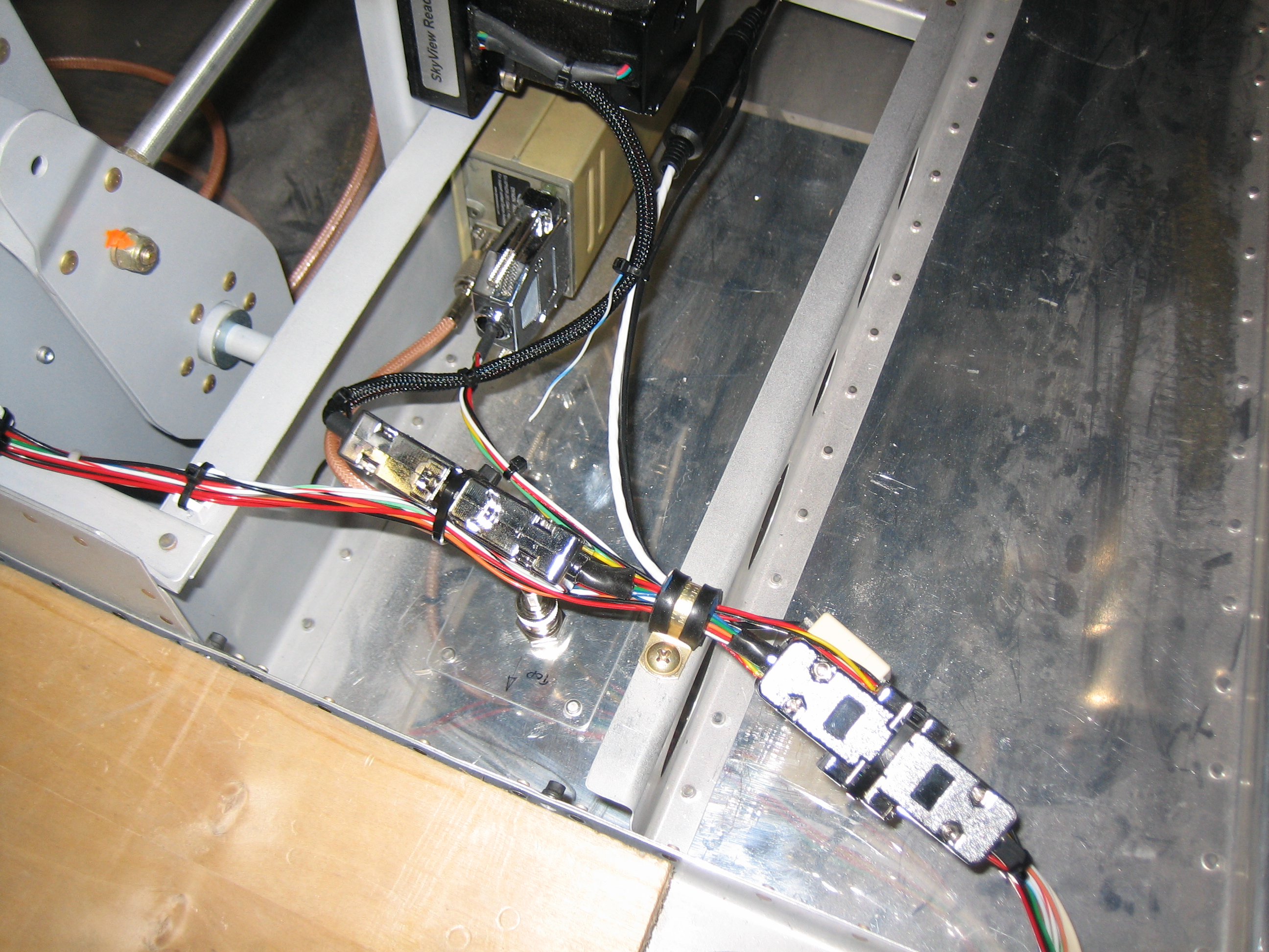
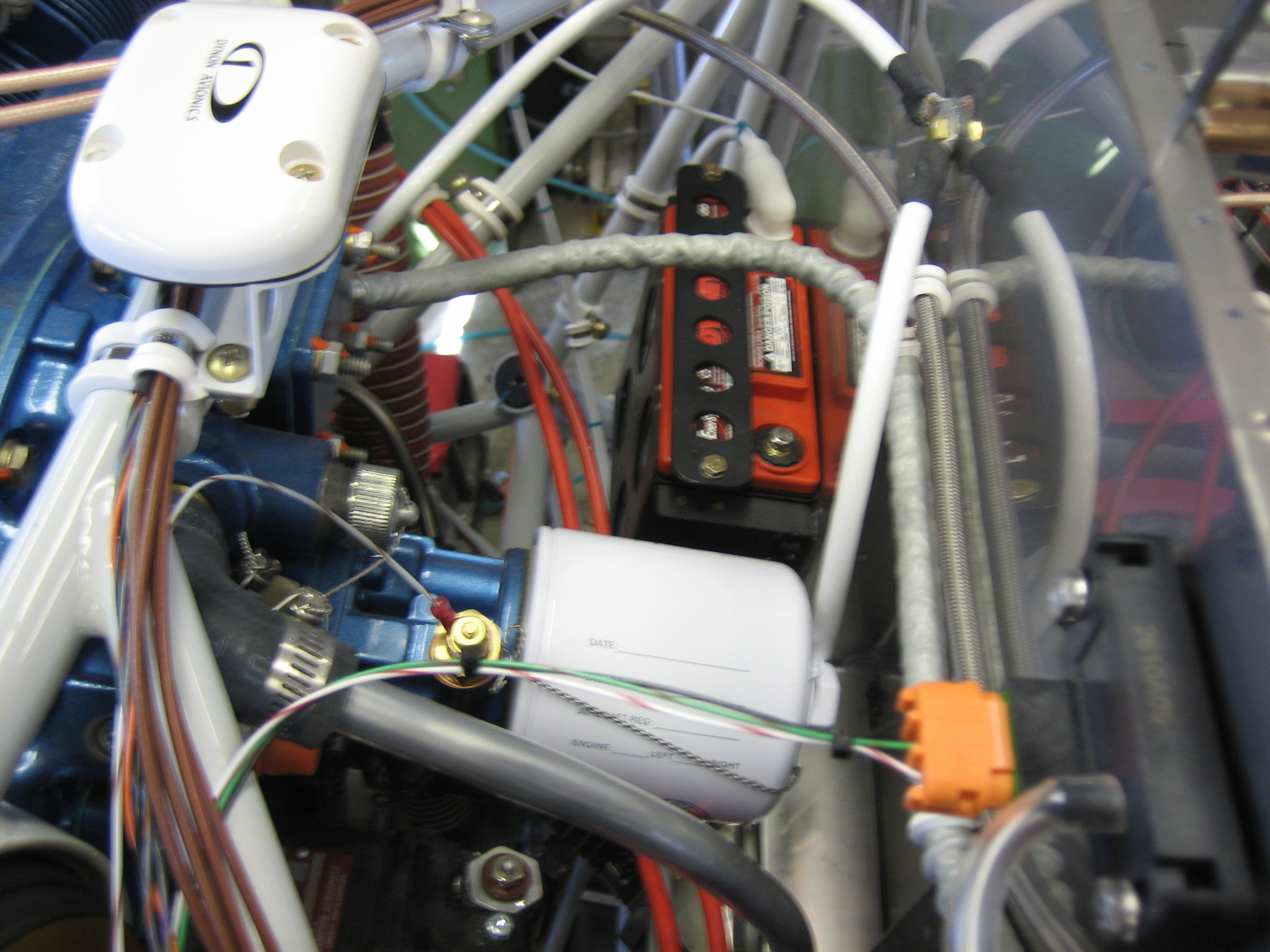
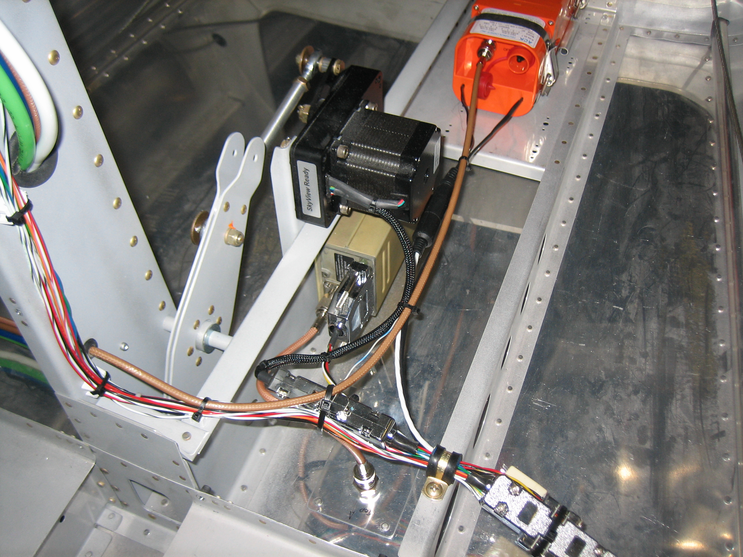
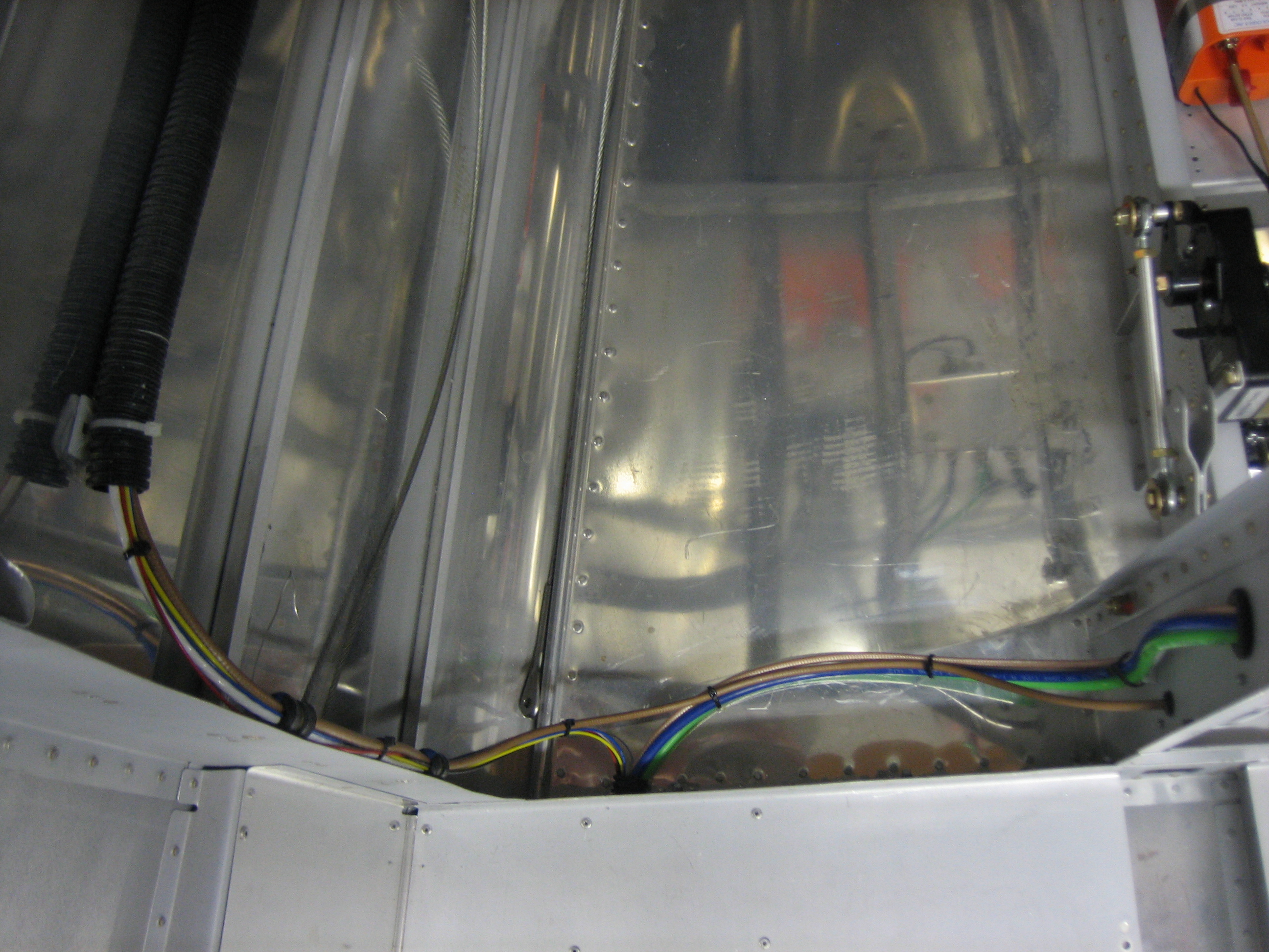
I spent a little time tonight tidying up some wiring runs under the seats.  I installed an adel clamp on the wires to the left of the center tunnel.  I haven’t tightened either of these down fully yet since I want to wait until the GPS antenna cable is adjusted to length and I still need to run the wires for the control sticks.

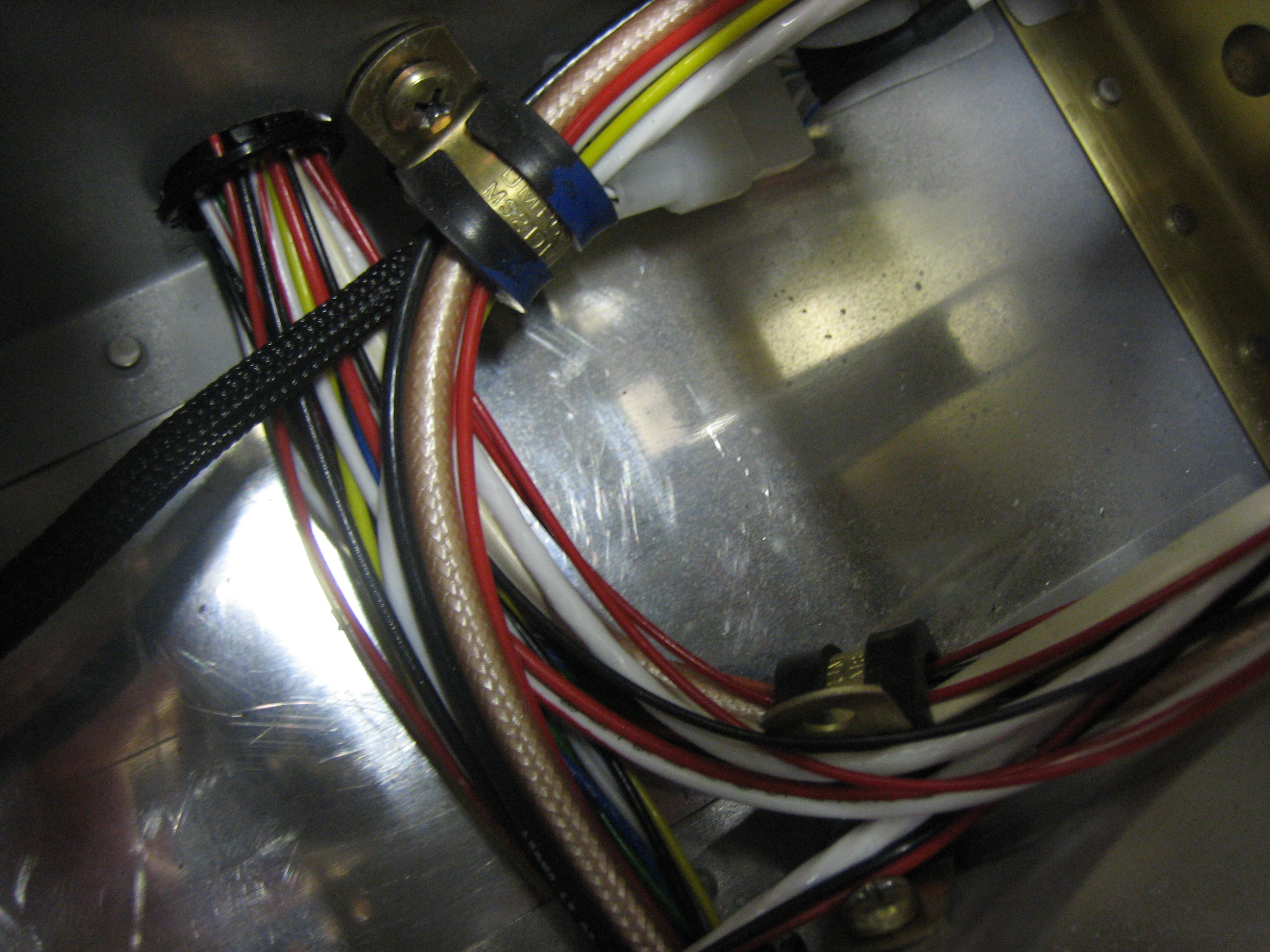
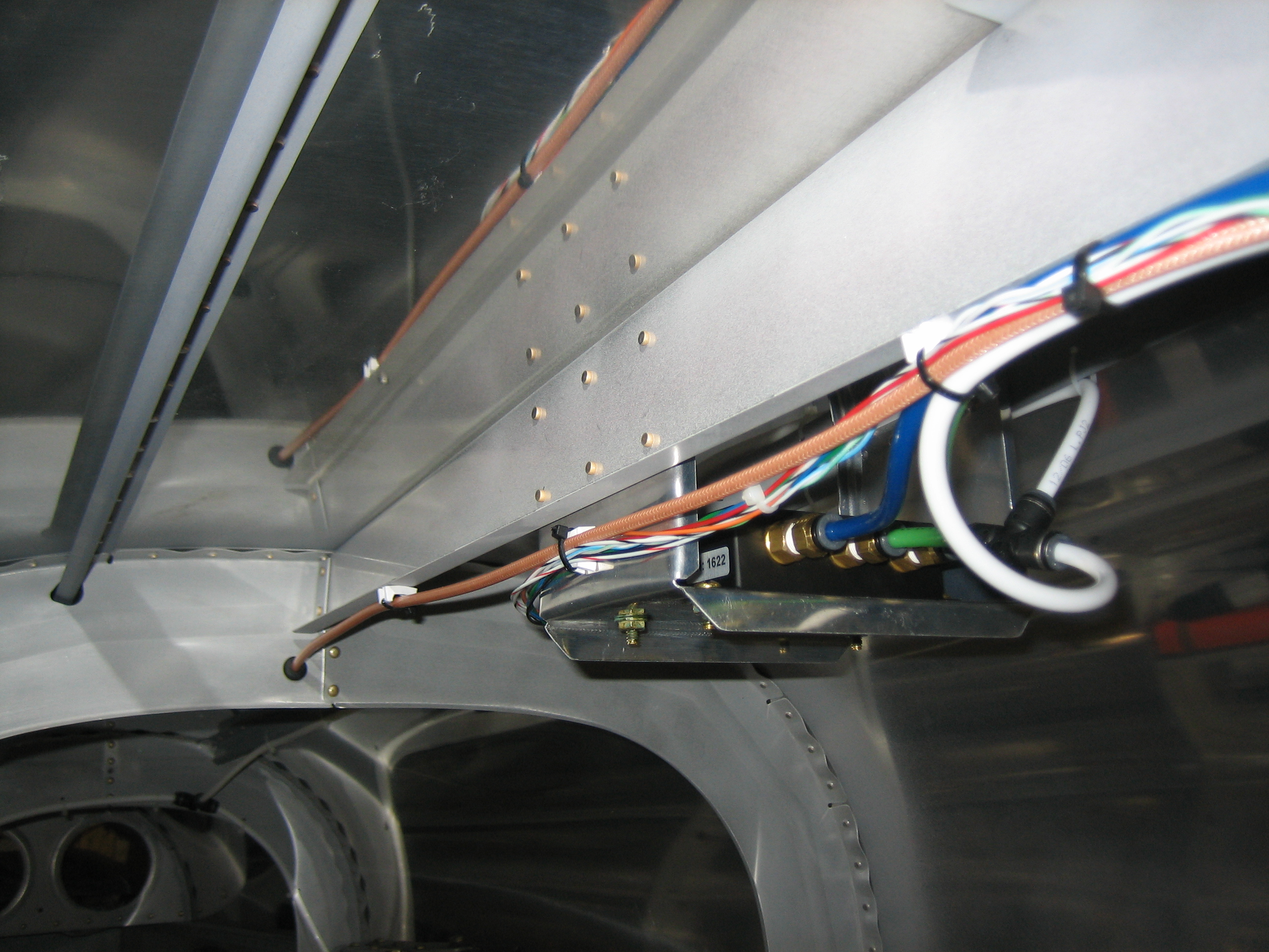
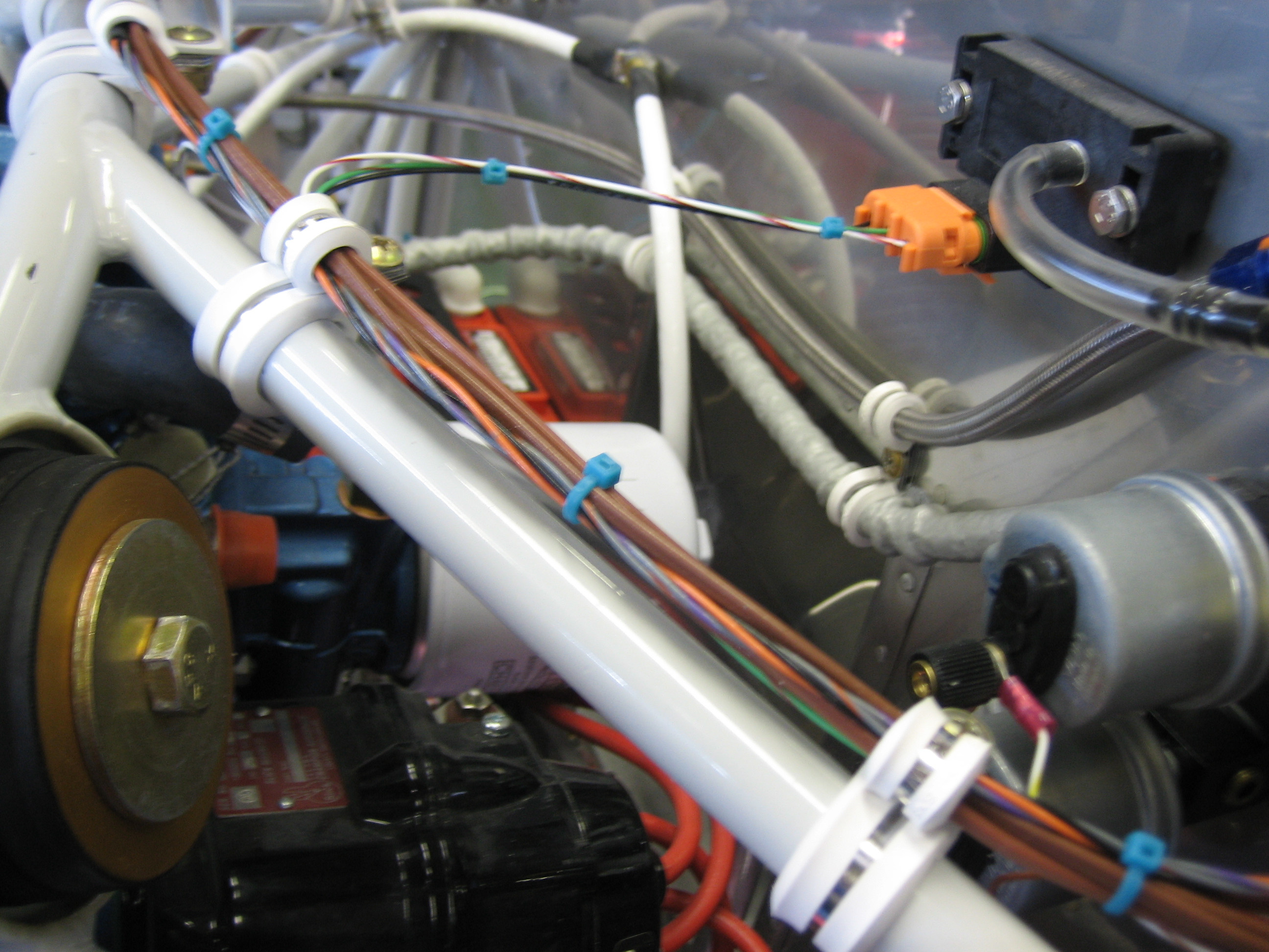
I installed the adel clamp supporting the wires coming out of the left conduit and added a couple of zip-ties to tie everything together.  It’s amazing how solid these wire bundles become when zip-tied together.

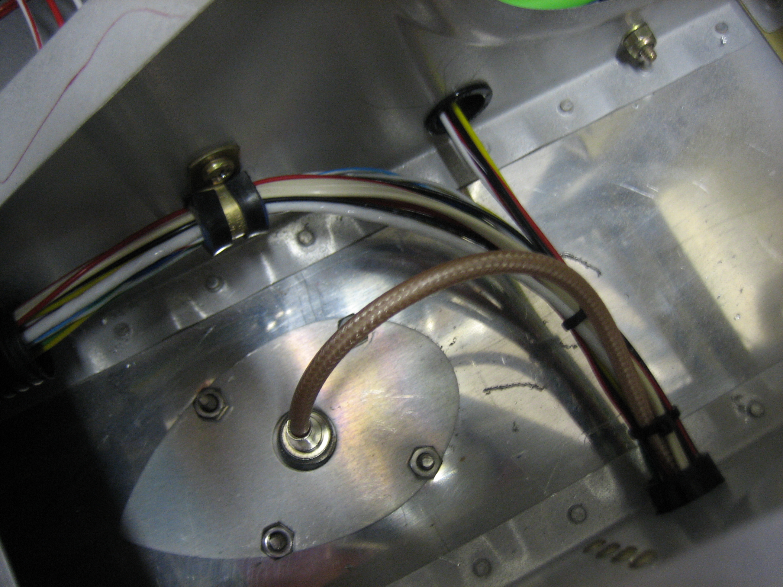
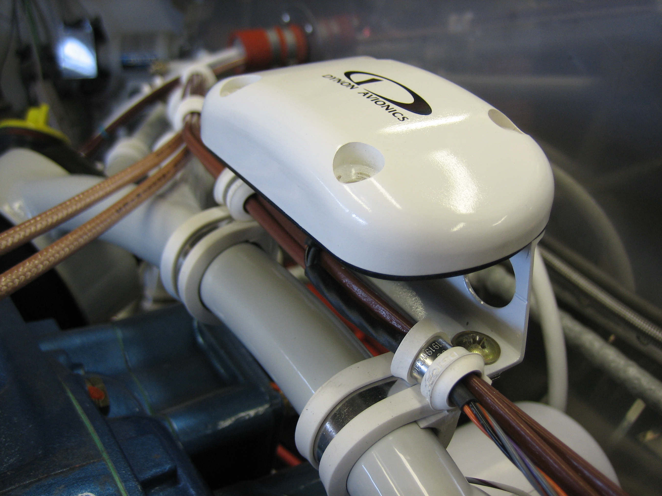
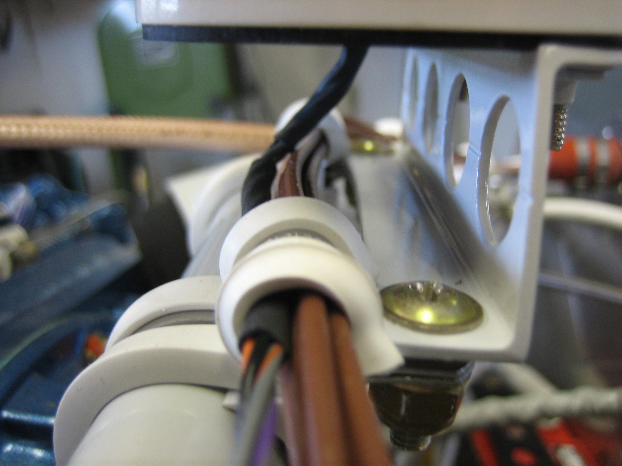
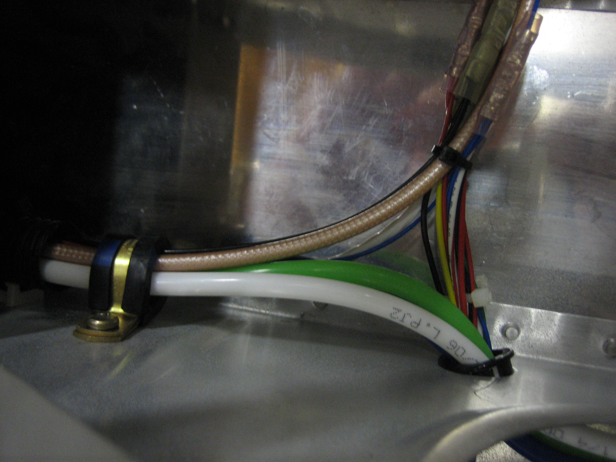
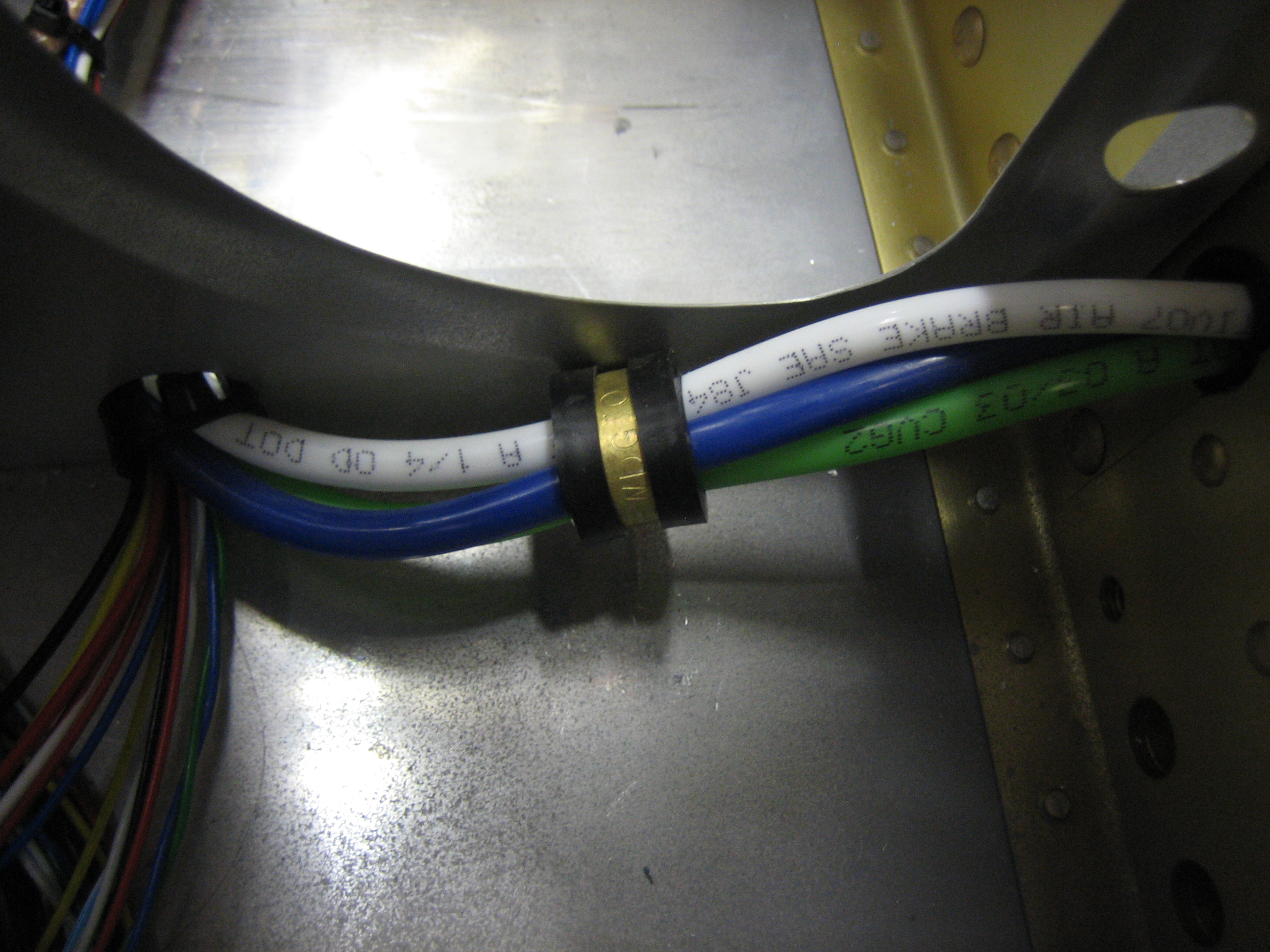
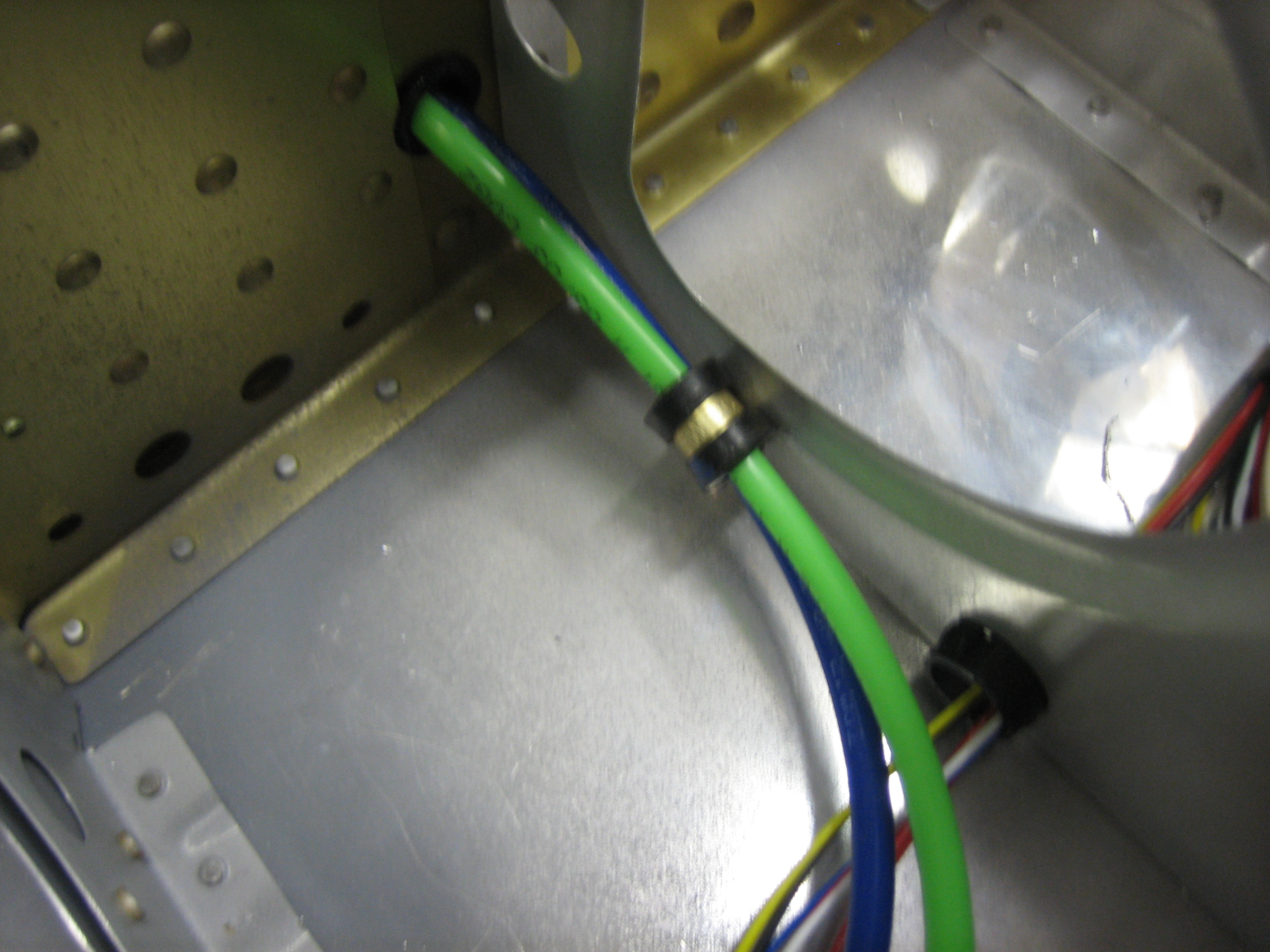
I added an adel clamp to keep the pitot/AOA lines held down to avoid interfering with the aileron push tube.  I might have been able to use a zip-tie base attached with a pop-rivet, but I really don’t want there to be any possibility of anything coming loose around the flight controls.  You can also see at the top of this picture that I took all of the snap bushings out of the forward holes in each seat rib.  I have no idea why Van’s has you drill holes here.  It’s a really poor place to put them since they’d have to snake around the control stick brackets.

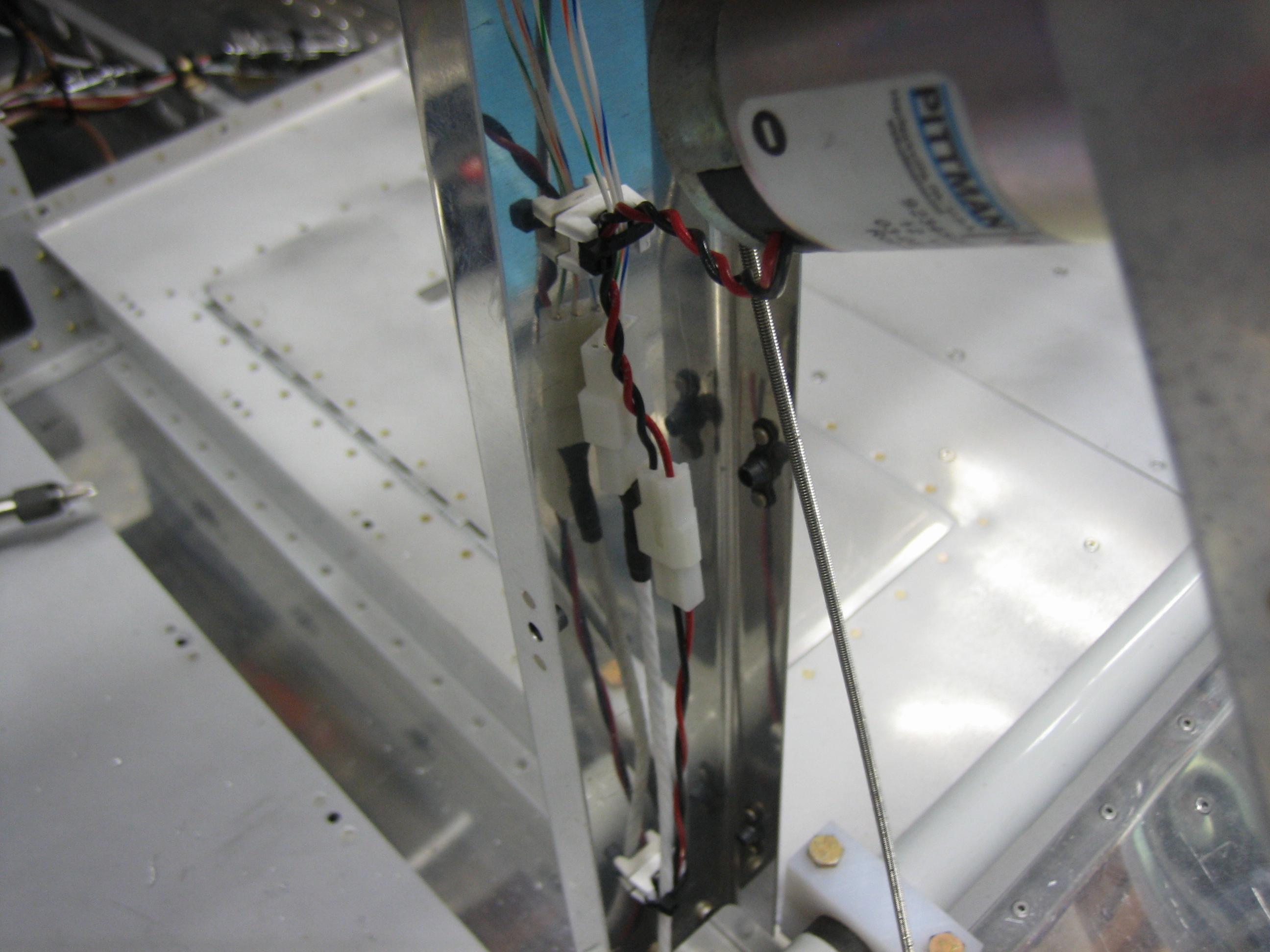
I also tidied up the wiring aft of the baggage bulkhead.  Everything is firmly secured and well supported.

Installed Garmin GTN 635 Antenna

I stopped by my avionics shop over lunch today and picked up the GA 35 antenna for my GTN 635.  Dynon recommends installing any GPS antennas at least 1′ from the ADAHRS, and Garmin recommends installing the GPS antenna with at least 7.5″ ground plane all the way around the antenna.  These two recommendations necessitated moving the antenna behind the F-707 bulkhead.  I fabricated a doubler from 0.040″ aluminum that matches the outline of the antenna and then installed it to the fuselage.

Here’s where the antenna is relative to the aft window.  The ADAHRS is roughly under the aft edge of that piece of paper, putting it roughly 18″ from the GPS antenna.

Afterward, I crimped on a TNC connector and ran the antenna cable along the underside of the upper rib next to the Dynon network cable.

Installed GPS Mount and Started Instrument Panel

With the mounting bracket painted, I installed it on the engine mount.

The EGT and CHT wires from cylinders 1 and 3 run under the bracket and pick up the GPS wires.

There is still plenty of access to the back of the engine for oil changes and maintenance.  I like this approach so much better than the shelf that many builders go with.

I then finished up securing the wires along the top left engine mount tube.  This bundle picks up the oil temperature sensor, manifold pressure sensor, oil pressure sensor and fuel pressure sensor wires along the way.

I’ve been working on my panel layout on and off for many months.  I’m happy with it now, so I started transferring it to the panel this afternoon.  You can’t see much here, but my computer model was perfect.  Everything fits exactly as it should with the clearances I determined in the computer.

Here’s a rendering of the panel from the modeling software.  The only thing not pictured here is the hobbs meter.

Ramp Crossing Bends and Instrument Panel Prep

I trimmed the forward ends of the ramps to within 1/2″ of the final dimension and them marked them for the crossing bends.  These bends allow the ramps to follow the slope of the cowl inlet.  The ramp on the left side is pretty deep since the air filter will be installed here.

The ramp on the right side is quite a bit shorter since the #1 cylinder is farther forward.

From the back side, you can see that the ramp follows the slope of the cowl inlet.  The ramp will get trimmed to be exactly flush with the inlet and a piece of baffle seal material will bridge the gap to prevent air from leaking.

I also trimmed off 1/2″ from the top of the Experimental Air throttle bracket so that I can have a little more knee room.

I’m going to have this TIG welded to the bottom of the instrument panel, flush with the front of the panel.  I’ll grind the weld flat so that this will be a seamless transition once painted.

Finished Tailcone Wiring (For Reals)

I thought I finished all of the tailcone wiring a couple of weeks ago, but I had forgotten about the OAT probe and ELT antenna cable.  I drilled a new hole in the vertical rib for the antenna cable to avoid too tight of a bend radius.

On the right side of the fuselage, the cable follows the tubing run and then jumps over to the tailcone wire bundle and follows it into the conduit.

I also installed a couple of adel clamps under the seat.  This one supports the wires and tubing as they come out of the front end of the right conduit.

I installed another one on the other side of the same rib to keep the tubing from interfering with the aileron pushrods.

I also installed a couple of zip-tie bases in the aft flap cover to support the flap motor and position sensor wires.  There are not installed permanently right now, but I wanted to anchor them so that I could determine the final wire length.

Finally, I recreated my upper left switch layout with some scrap aluminum to make sure I was happy with the spacing.  I spent a few minutes playing with it and I think it’s perfect.  The spacing I settled on was 1 1/4″ horizontally and 1 9/16″ vertically.

Received Avionics Stack

I picked up my avionics stack from Aerial Avionics today.  They’re a local company, but they were willing to match a price quote from I got from Stark Avionics.  I got a PS Engineering PMA 8000BT audio panel and a Garmin GTN 635 GPS/COM.

They built the wiring harness as well.  I went through the whole thing so that I could fully understand all of the interconnects.  Other than installing an unnecessary marker beacon antenna cable (which I removed), everything looks perfect.  Despite what looks like a rats nest, these are nicely organized and grouped together according to where they need to be routed in the airplane.  The only mistake I made was forgetting to request that they use red wires for power and black for ground like I’ve done with all of the other avionics in the plane.

Fabricated Avionics Stack Mounting Brackets

After carefully aligning the trays, I drilled some 1/16″ angle to them so that they can be mounted to the instrument panel.

The 1/16″ angles are set back by the thickness of the instrument panel.  Using a piece of scrap here the same thickness, you can see that the faceplates of the radio will be flush with the front of the panel once installed.  Next up will be to cut the hole in the panel and subpanel for the avionics stack.

Started Cutting Panel

I wanted to get started cutting the panel tonight.  First up though, I needed to fill two of the holes that are normally used to attach the panel to the ribs.  Since I’m moving the ribs inboard, these will no longer be used.  The top holes on each side (and the one in the middle that is normally used for the canopy ejection handle) all fall within avionics cutouts, but the bottom holes on each side will be visible beneath the SkyView screens.  I countersunk the holes and installed AN426AD5-4 rivets in them.  When I prep the panel for paint, I’ll sand/fill this so that it will be invisible.

I then cut out the hole for the avionics stack.  The hole is really tight vertically now (and just right horizontally).  I’ll extend the bottom edge of the hole down 1/16″ or so to make a little more room.

Along the side, you can see that the avionics are completely flush with the panel.  Once I move the stack down a tiny bit, I’ll line up and cut the holes for the SkyView panels.

Cut Holes for SkyView Screens

I extended the hole for the radio stack downward by 3/32″ and then cut the holes for the SkyView screens so that the top edges of the screens are aligned with the top of the audio panel.  The holes need a little more filing since the screens are a pretty tight fit right now, but they’re close.  Once I’m happy with the fit, I can drill the mounting holes which will simultaneously lock in the position of the SkyView screens and radio stack mounting rails.  Everything else will be mounted relative to these items.

Mounted SkyView Screens

After enlarging the SkyView screen holes slightly, I clamped a straightedge along the top of the radio stack and made sure it was aligned with the bottom edge of the panel, then pushed the SkyView screens up against the straightedge and moved them as far inboard as they could go.  I used a couple of wood blocks to hold the SkyView screens in position while I drilled a couple of the mounting holes to lock in the final position.  You can see I used some extra tape and a paper towel to keep any metal shavings out of the avionics.

I fit the panel in the plane to determine where the ribs need to be mounted.

I’m going to use some 1/16″ angle to attach these ribs to the subpanel.  Some additional 1/16″ angle on the other side of the subpanel (mounted horizontally) will be used to box in the hole in the subpanel to strengthen it.

A few minutes with various nibblers and snips and I have this hole in the subpanel.  The sides and bottom edge are aligned with the sides and bottom edge of the radio stack hole in the panel.  The top edge is 5/16″ lower than the top edge of the hole in the panel since the audio panel tapers down in the middle and is pretty short.  Only the wiring harness will need to go through this hole.

I installed #6 nutplates in the outer SkyView mounting holes.  You can also see in this picture that I filed a radius into each corner of the screen cutout to avoid a stress riser.

For the radio stack, the nutplates are installed in the mounting rails.

I test fit the panel in the plane.  The hole in the subpanel is a little right, but it’s in exactly the right spot.

You can see how tight the sides are, but the opening on the top will be perfect for the wiring harness to slip through.

The clearance on the front side of the subpanel is great.  Plenty of room for the connectors to stick out and for the wiring harness.