Cabin Lights and SkyView Wiring

I received some interior lights from pilotlights.net.  They were great to work with and even through in a couple of small bonus products with my order.  I’m trying to use all dual color (white/green) interior lights.  From the research I’ve done, everyone is moving away from the old standard of red for cockpit lighting at night.  Although it did fine at preserving your night vision, it makes reading maps really hard.  The military has moved to green, but research has shown that a really dim white light is actually best for preserving night vision while still giving you the best visual clarity.

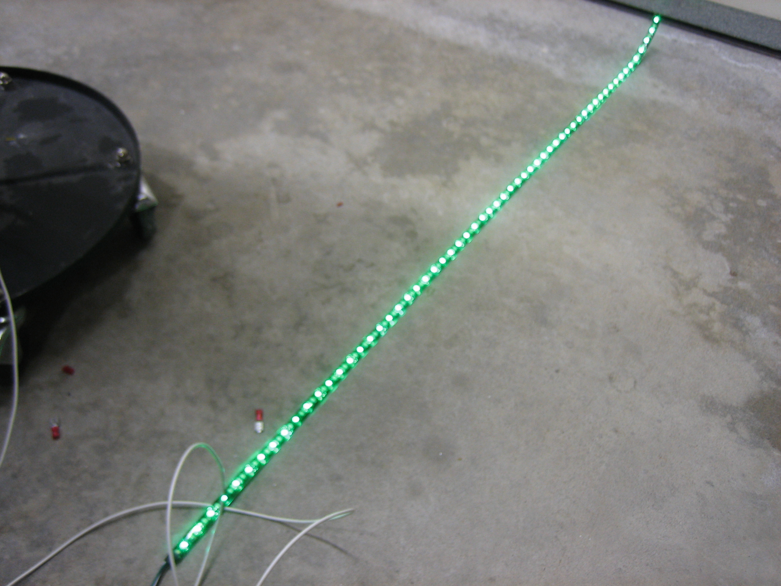
Here’s the LED light strip I’m going to use under the glareshield (this is the 12V, high-power, dual-color white/green strip).  This is with just the white LEDs illuminated at full power.  It’s hard to capture with a camera, but this is definitely more light than you’d need in a cockpit.

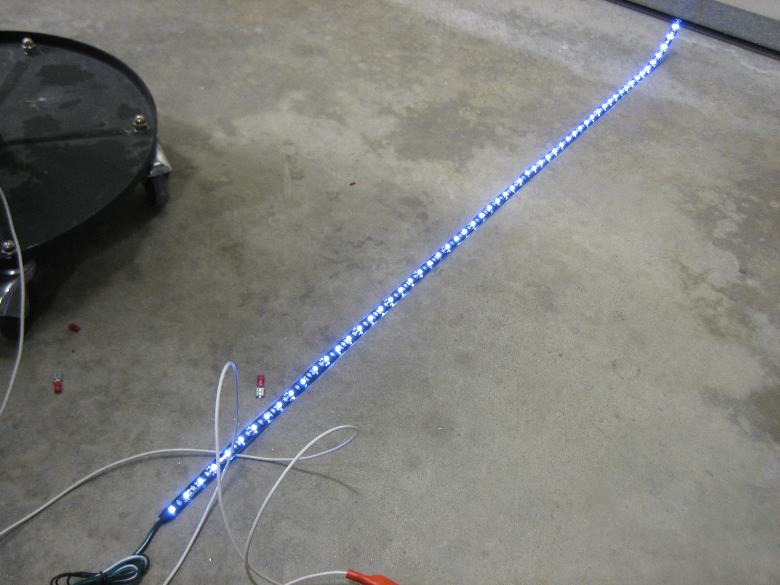
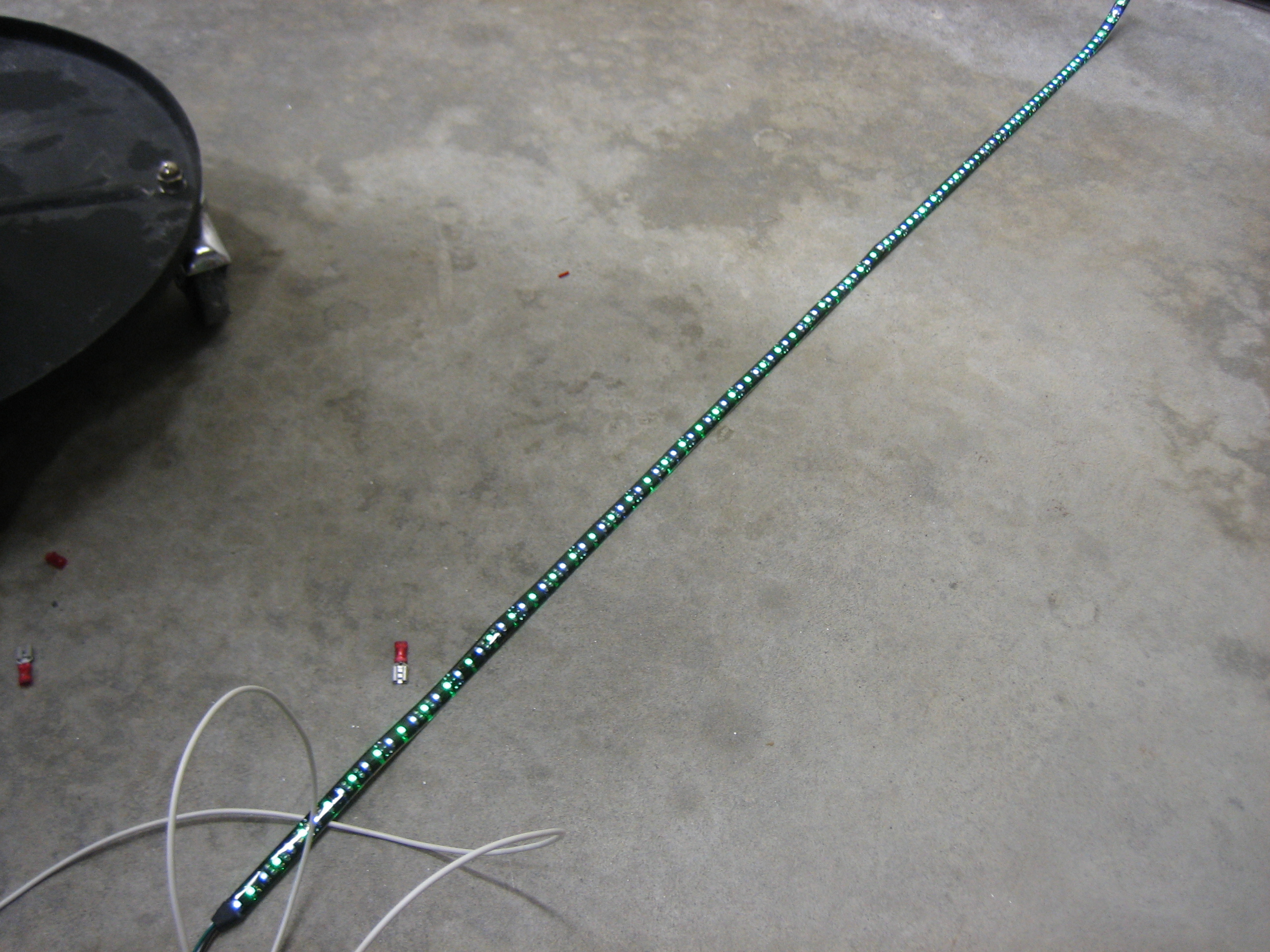
Here it is with just the green LEDs illuminated.

And here it is with both (although I’m not going to wire it in the plane with the ability to light both colors at the same time).

Using one of the PWM dimmers (also from pilotlights.net), you can dim the light down pretty far, but not quite far enough.  A dropping resistor of 150? or so makes the range just about perfect.  You can dim almost down to off and the brightest setting is still plenty bright.

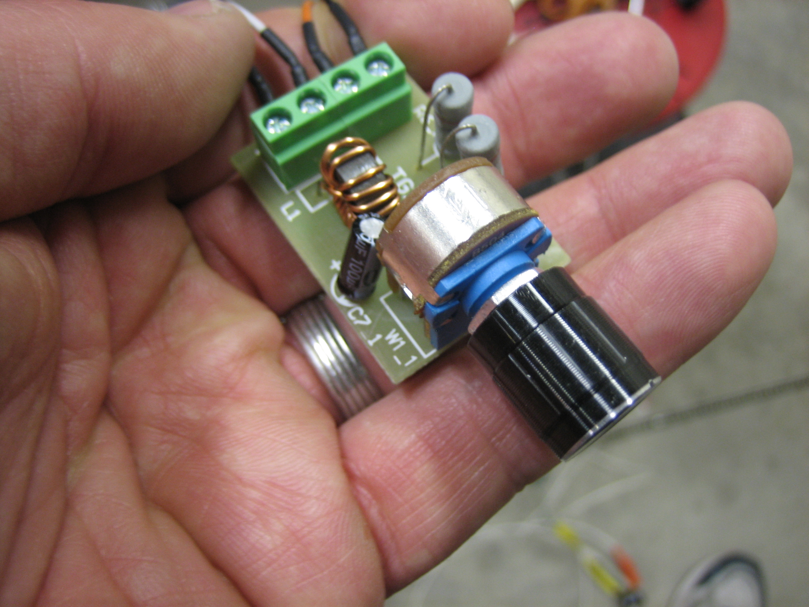
Here’s the PWM dimmer I’m using.  I bought three of these to replace the ones I purchased from periheliondesign.com.  The more I played with those, the less I liked them.  The lights flickered as you ramped up and down through the brightness range and putting the resistors to cap the low and high voltages wouldn’t expand the range of the dimming knob which means you would have to turn the knob a bit before it would come off the low dim setting and you’d hit the bright setting long before hitting the upper end of the knob’s range.  These PWM dimmers ramp smoothly across the whole range of the knob.  They also come with a much nicer machined aluminum knob instead of the plastic one on the dimmer from periheliondesign.com.

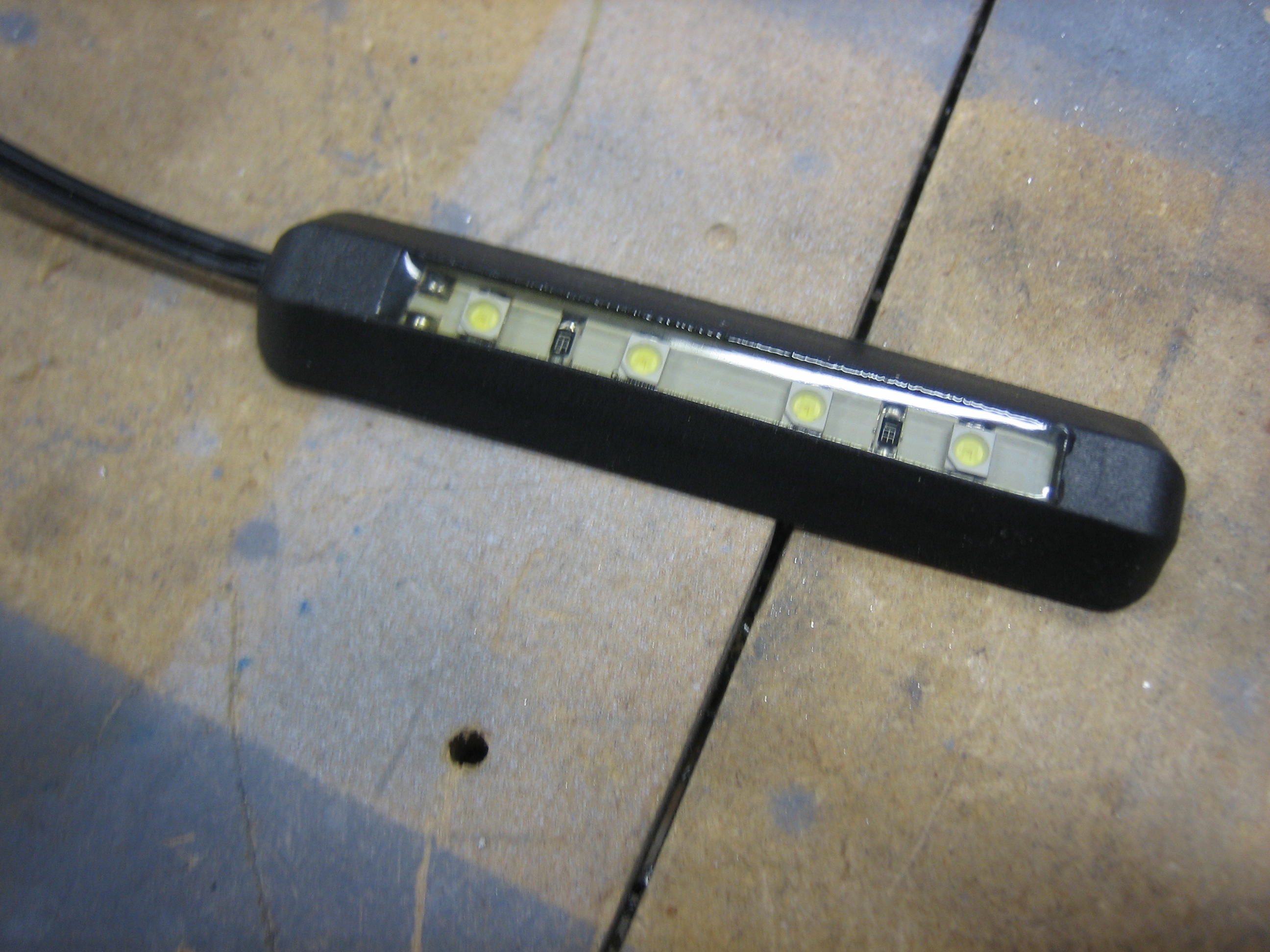
I also picked up this little four LED white light.  I’m going to put a dropping resistor on this and use it to cast a very dim light in the footwell.

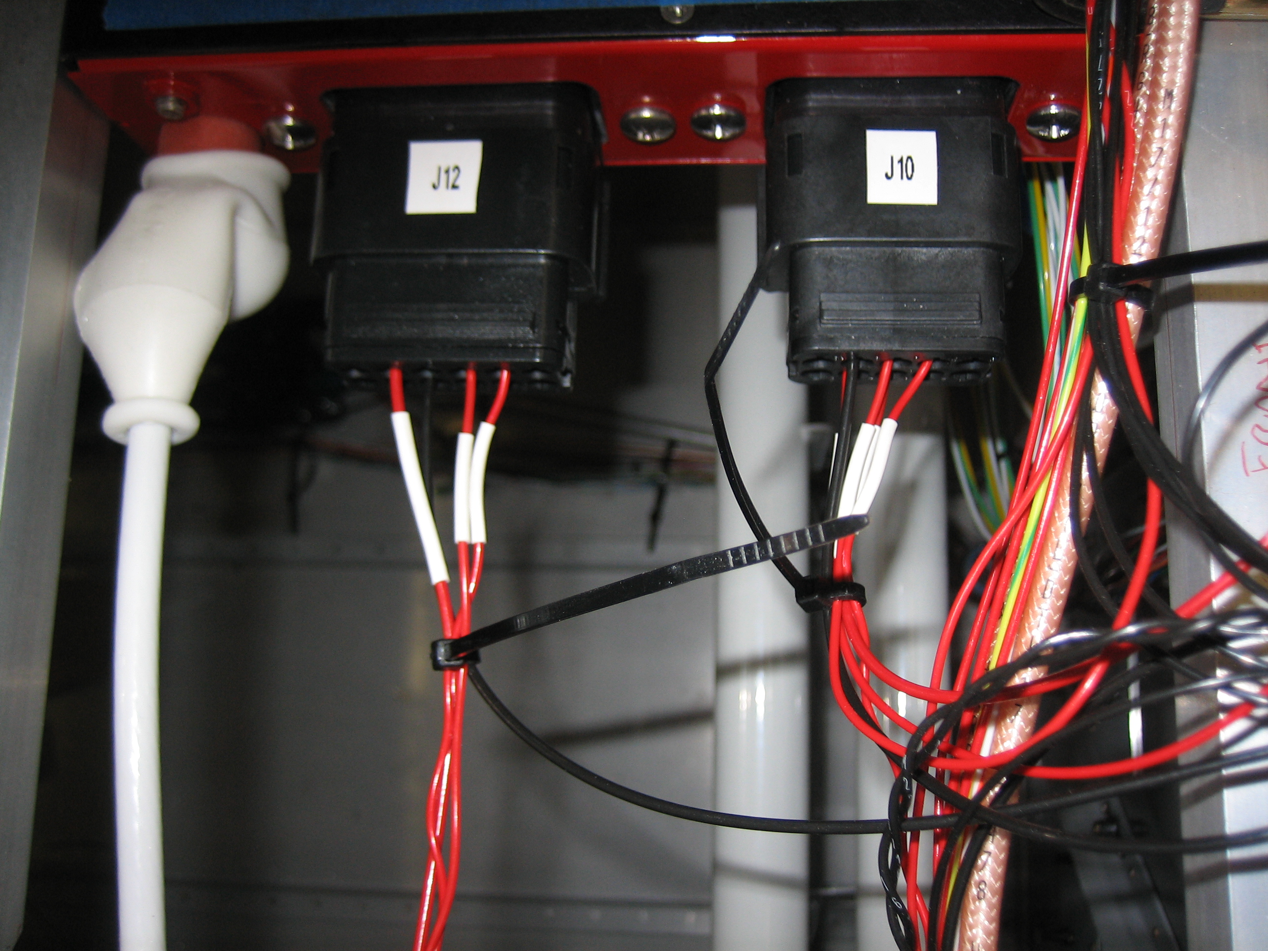
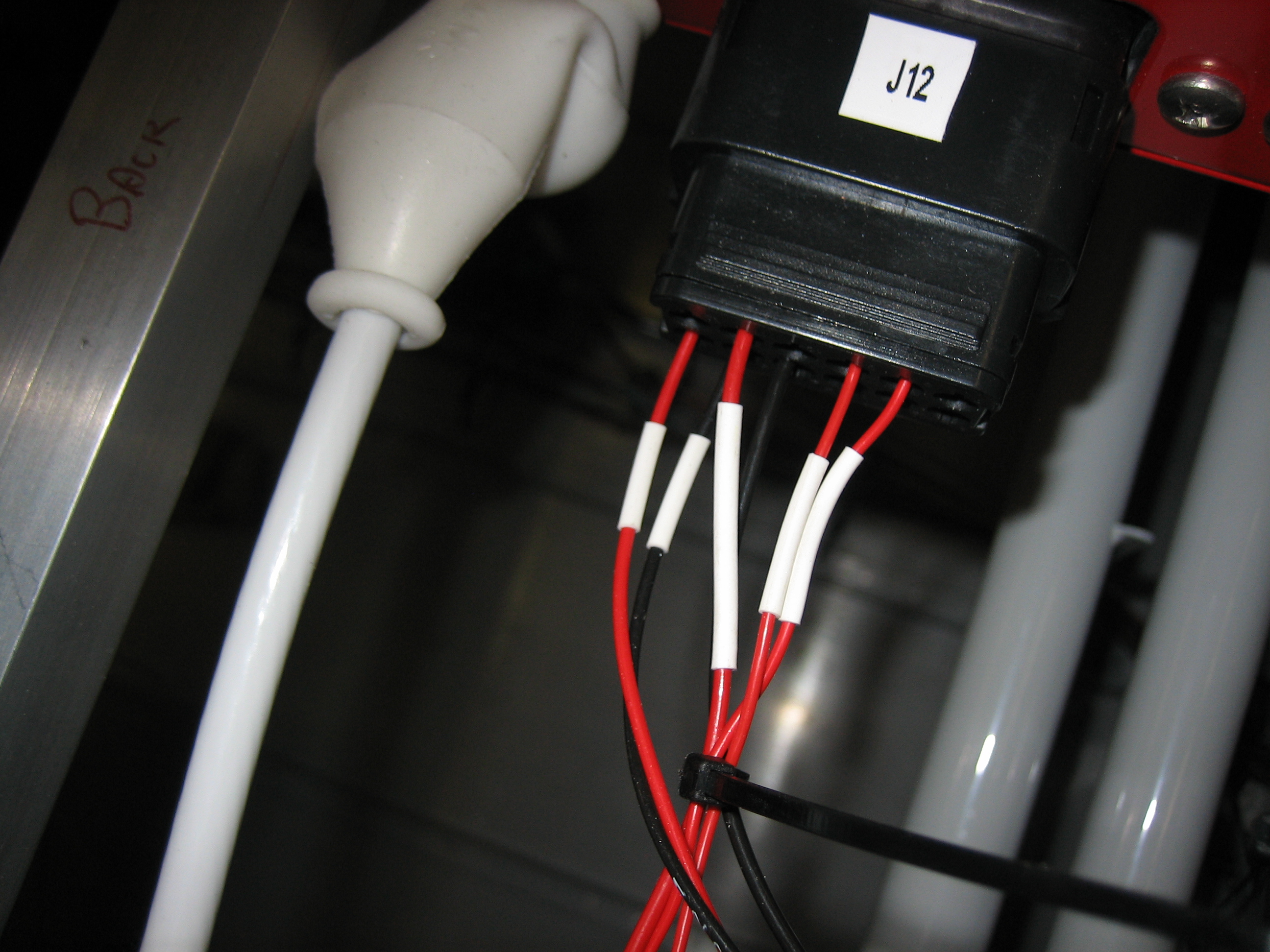
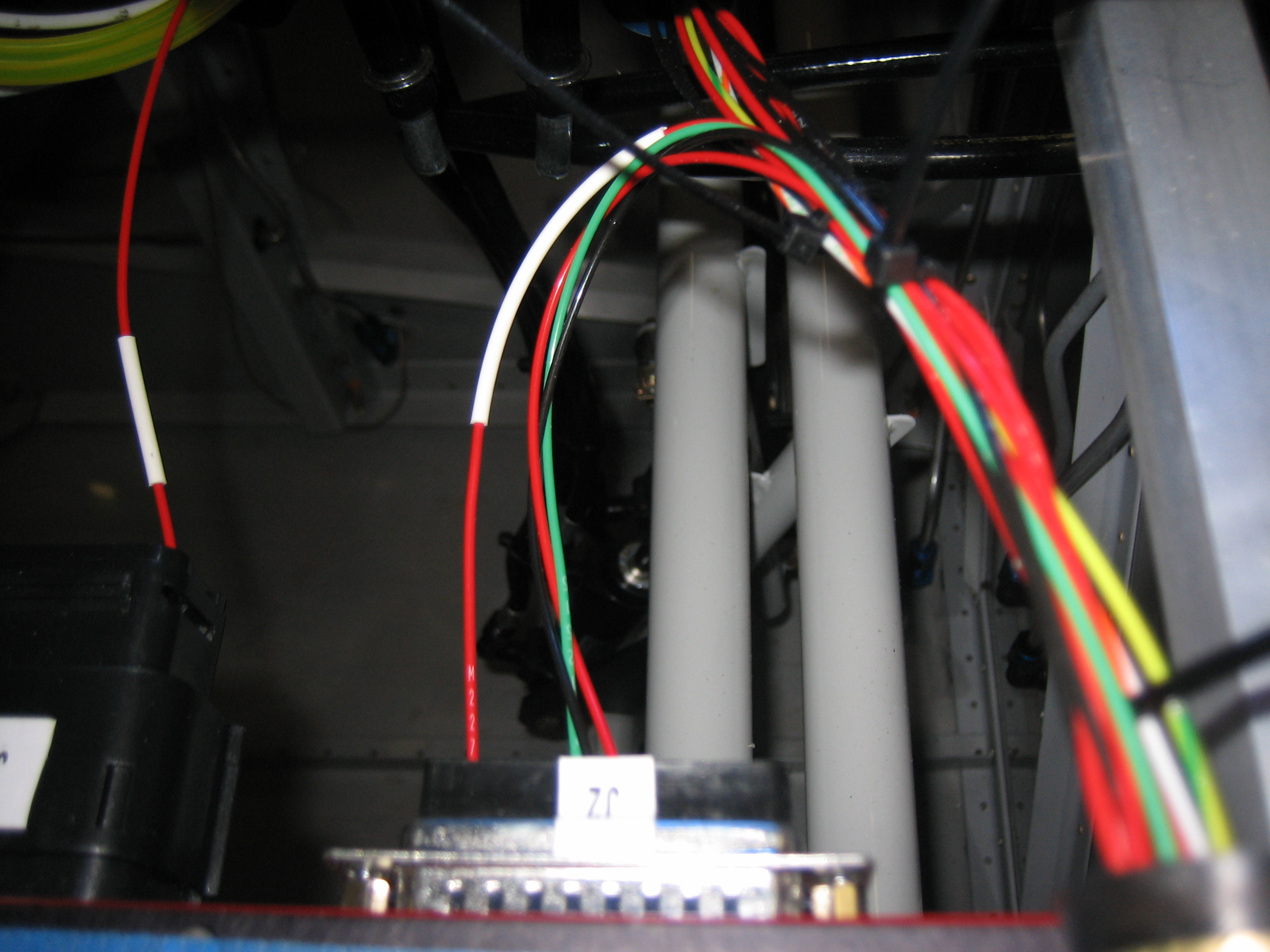
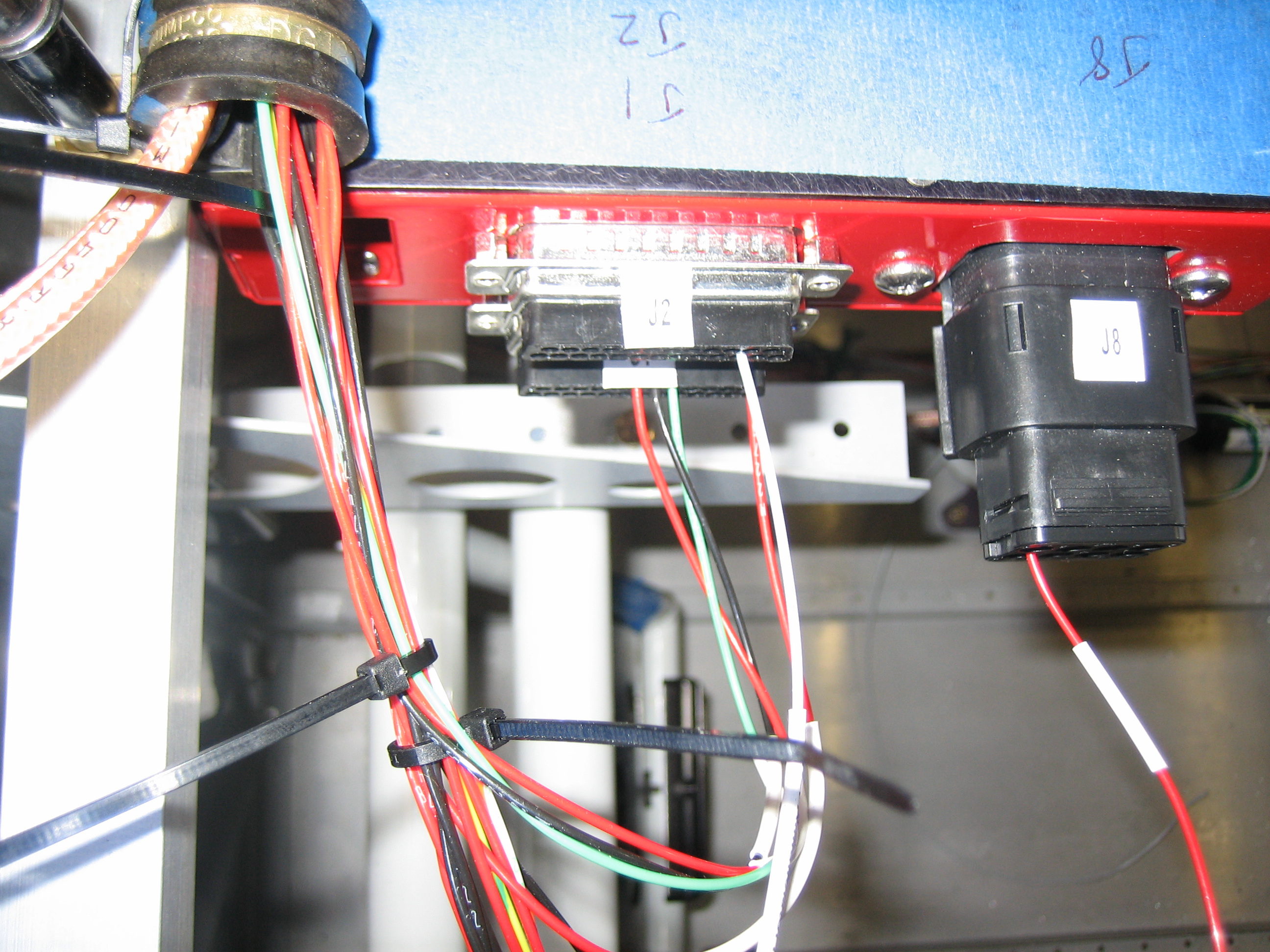
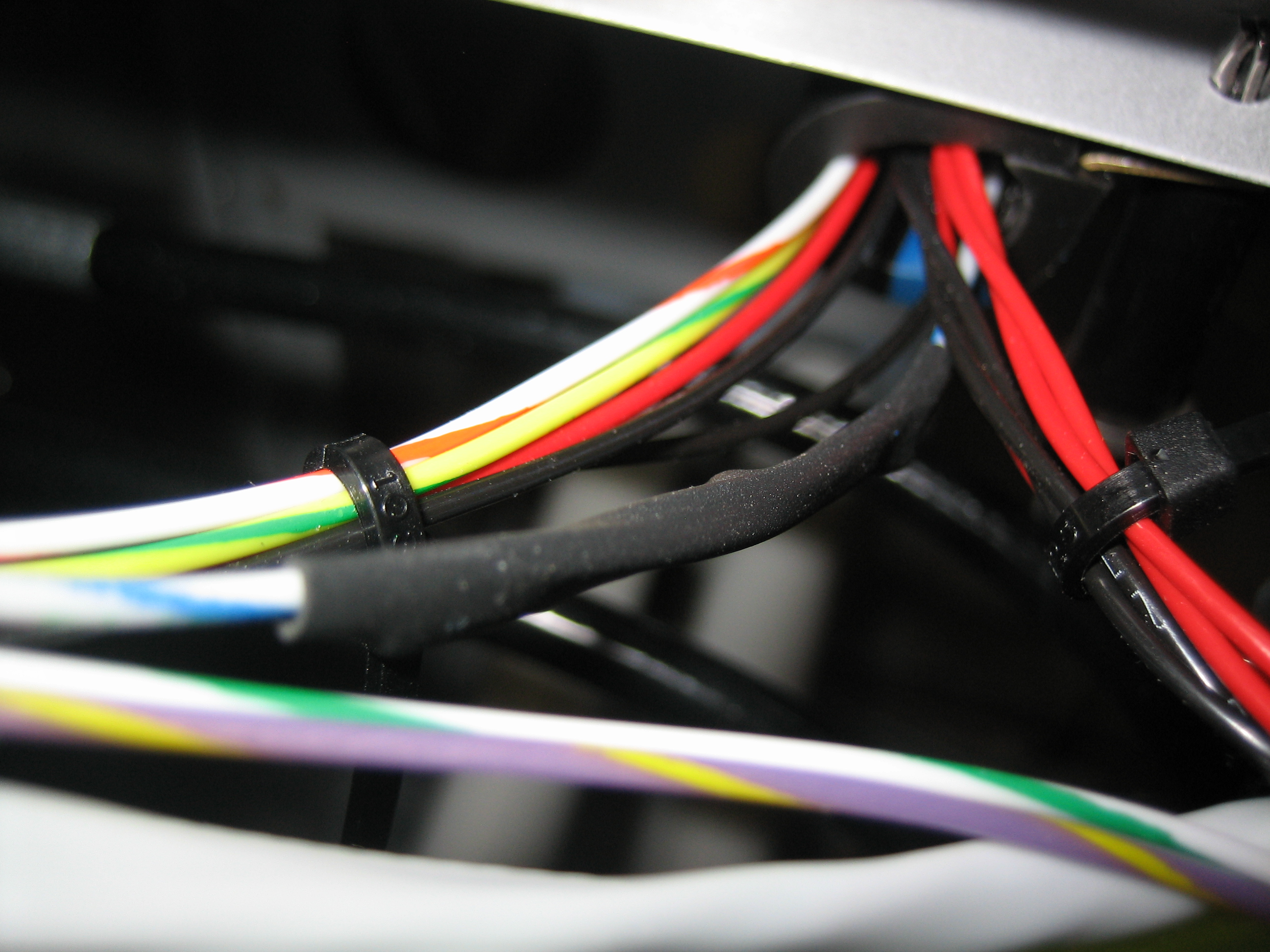
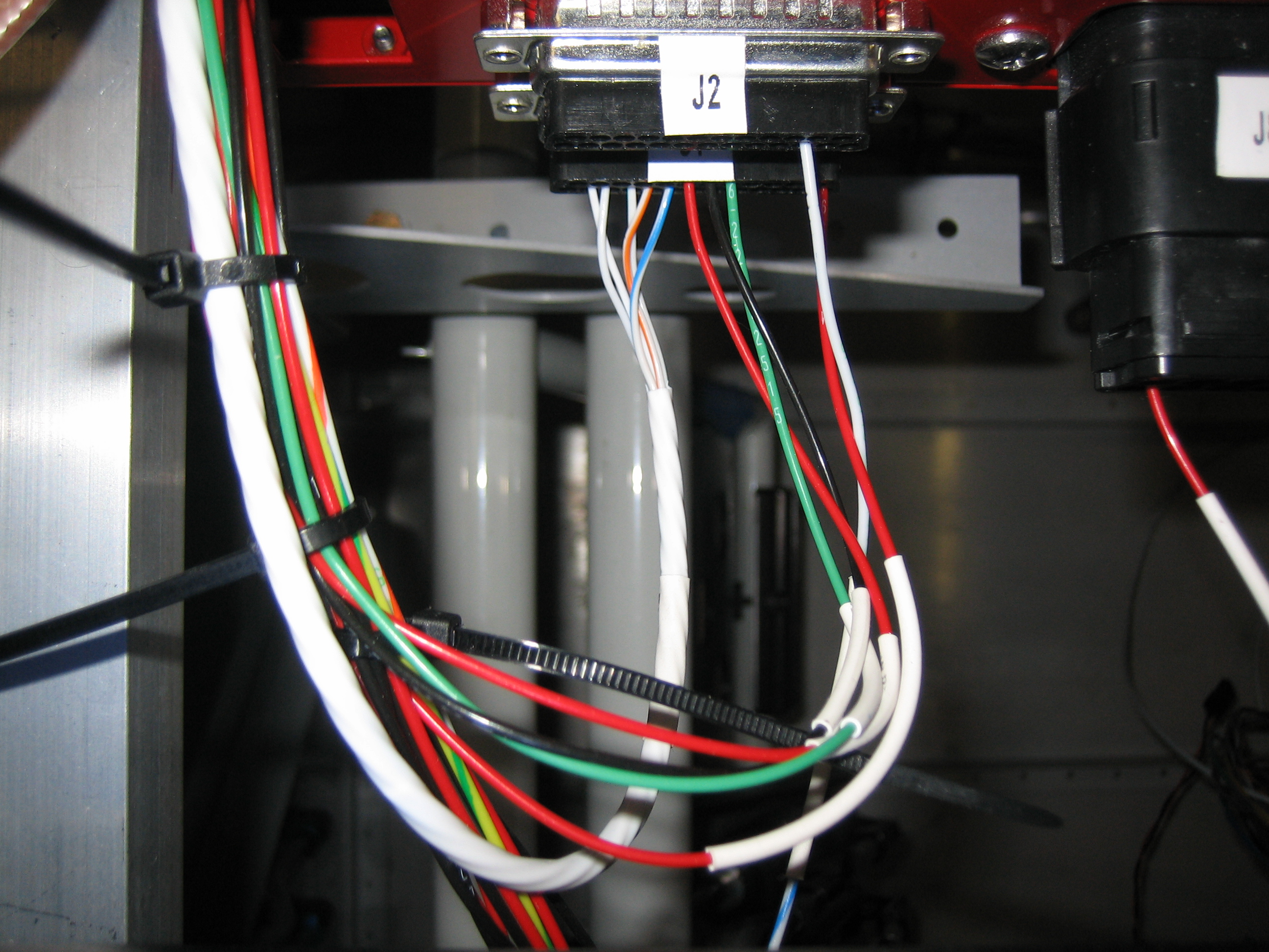
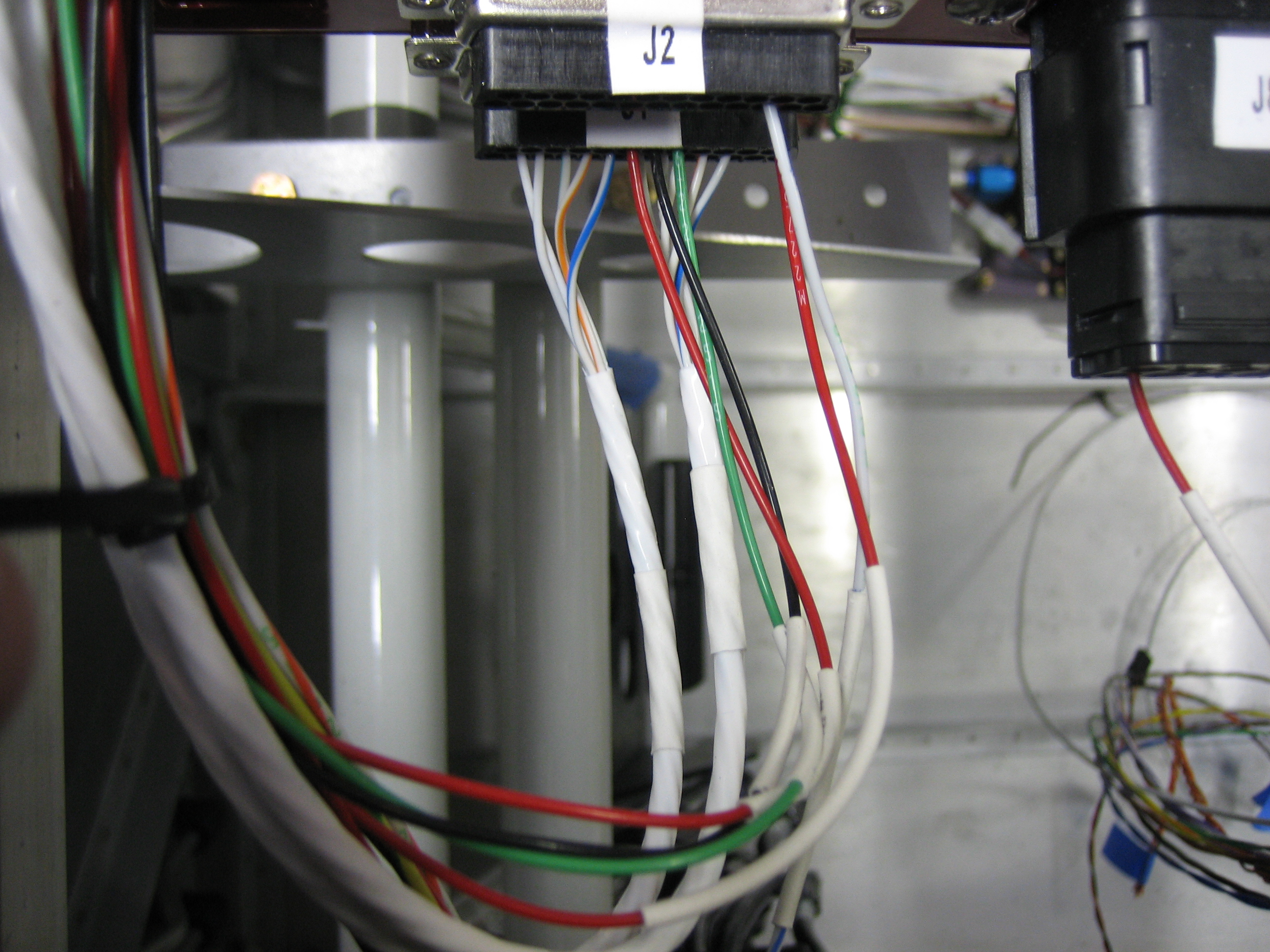
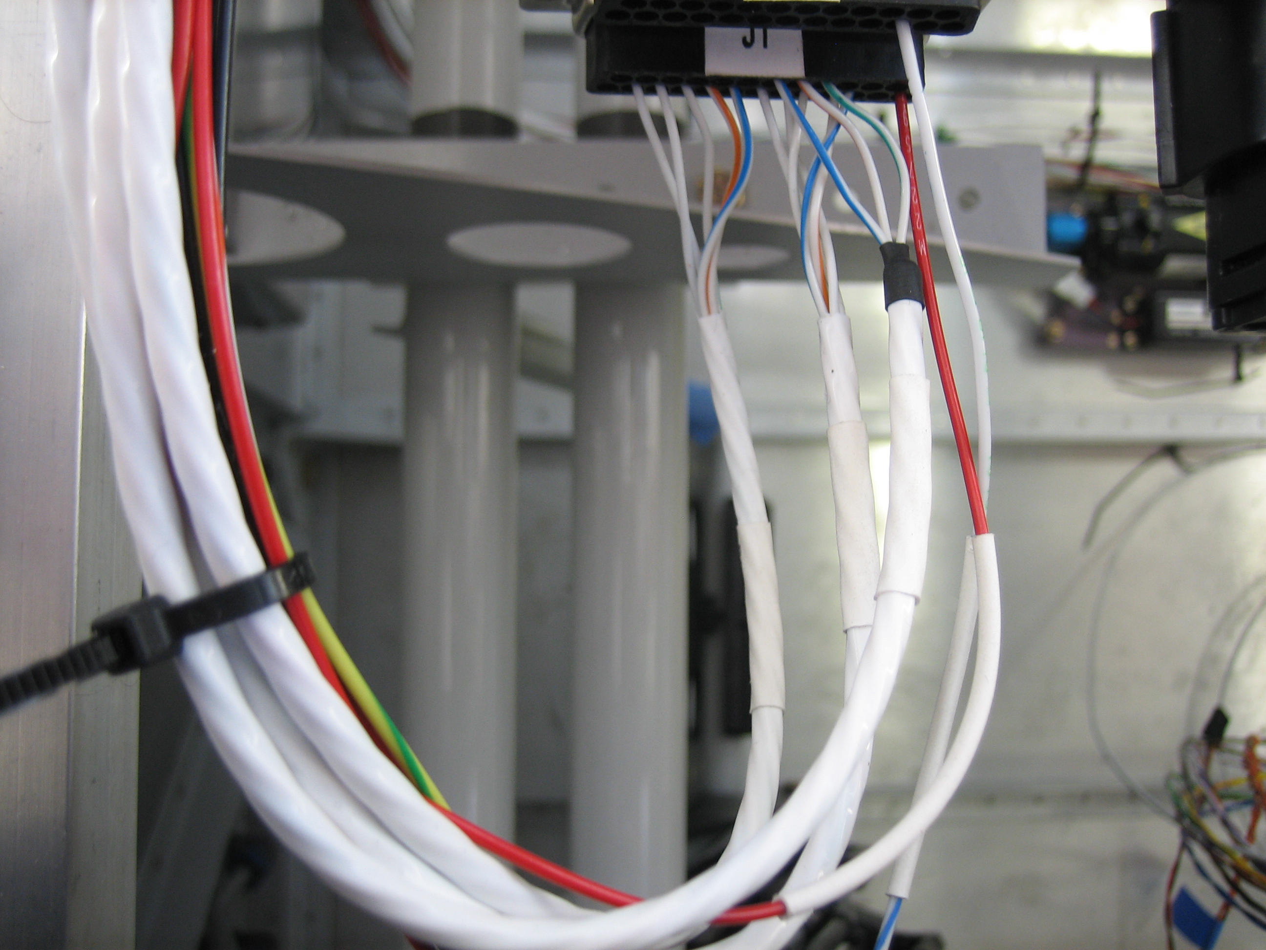
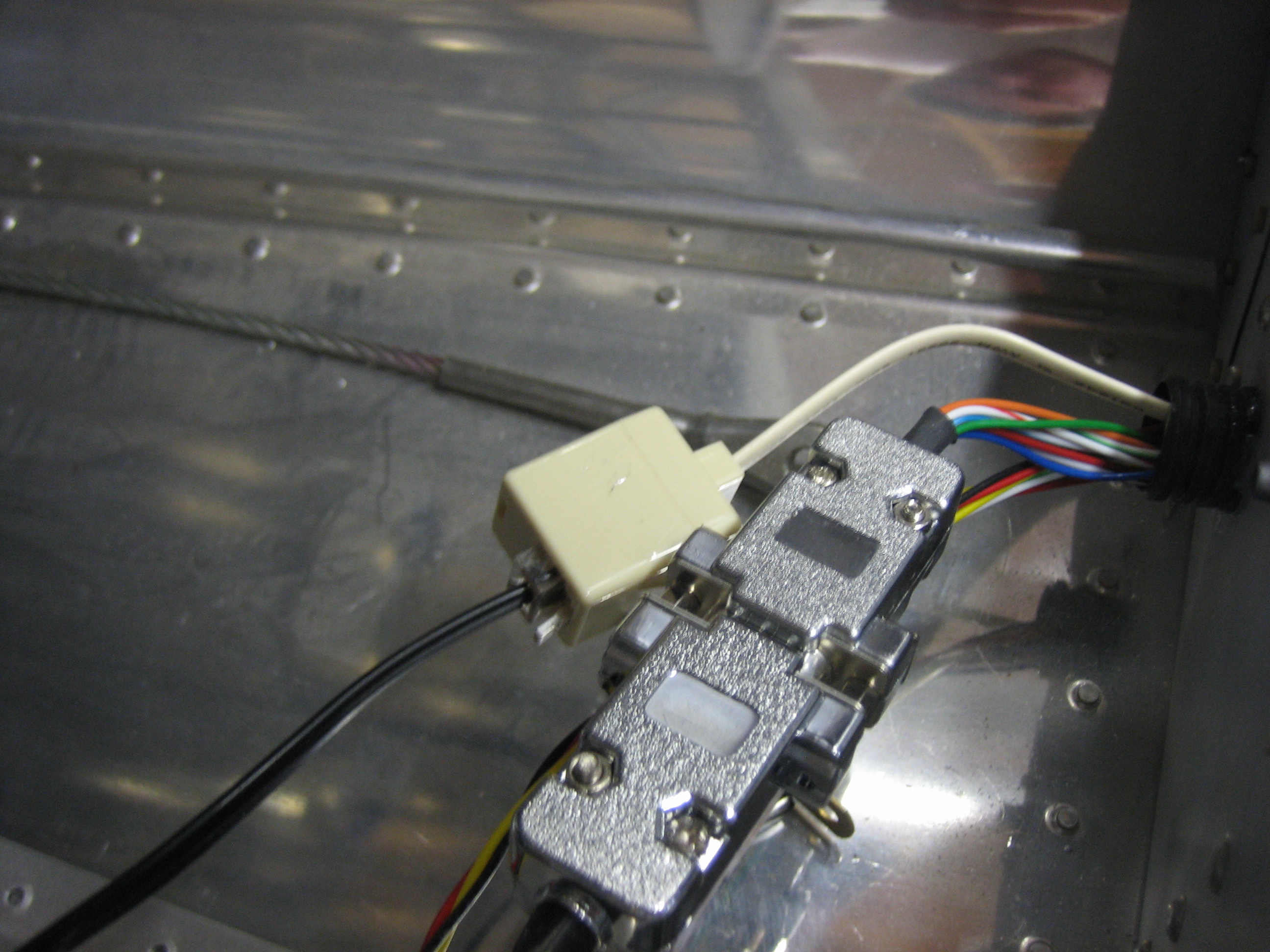
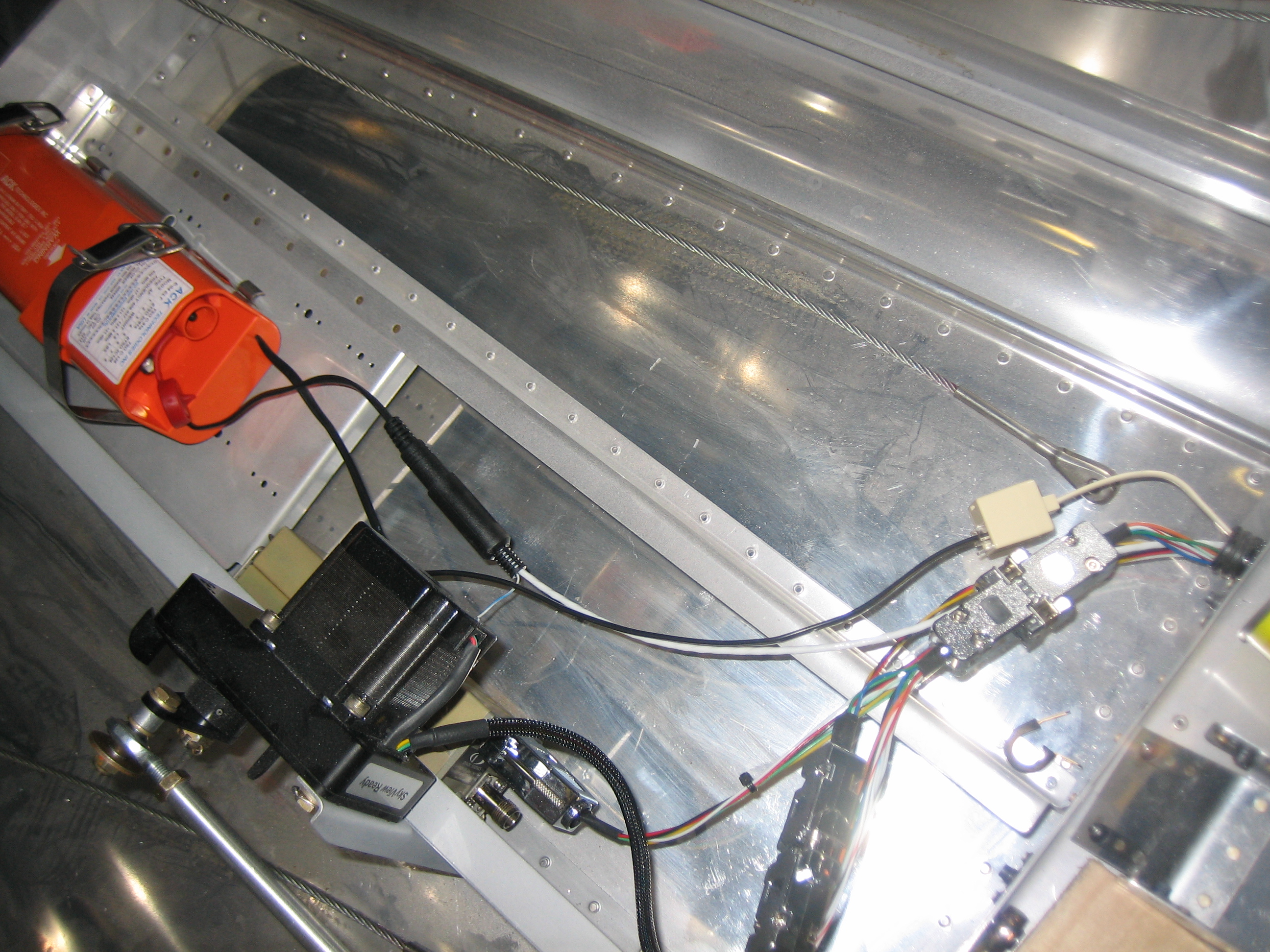
I also went ahead and hooked up the four SkyView power wires to various pins on J10 and J12.  Each SkyView has one power wire going to bank A and one going to bank B for redundancy.

Wired Flap Position Sensor

I’m working quite a lot of hours at work now, so I’m not getting much time on the plane, but I want to make some progress on the plane every day that I can.  Since I got the flaps wired up last night, I decided to wire up the flap position sensor tonight.  These will be the last wires that need to run down the center tunnel.  I installed a three position molex connector for the position sensor.  I’m still not sure how I’m going to anchor these to the rear cover.

I didn’t want the wires from the position sensor to rub the screws that attach the side covers to the flap housing, so I used a small drop of E6000 to secure the wires to the side of the position sensor.

I also swapped out the four position molex connectors on the fuel senders for three position connectors.

I attached the two flap wires to J12, pins 5 and 6 (the lower left red and black wires).

And the three flap position sensor wires to J1, pins 17, 18, and 19.

Wired Flap Motor

I ran the wires to the flap motor tonight.  I put a two position molex connector on the wires so that the motor can be easily disconnected if it needs to come out.  There will also be a second connector here for the three pins from the flap position sensor.

I cut away a chunk of the forward end of the aft tunnel cover (basically the part that will be inside the flap motor housing.

This lets the wire that runs down the flap tunnel pass through the rear spar before coming up behind the flap weldment.  All of this will be secured by some wire tie mounts to keep it from coming in contact with the weldment.

Installed Starter Annunciator Input to VP-X

I spent most of the day working, but I had a little time so I snuck out to the garage for a bit. I cleaned up some of the wire runs and installed the wire from the starter contactor to the VP-X so that I’ll get a “starter engaged” annunciation on the EFIS.

I put a 1kΩ resistor inline with the wire.  Unfortunately, I didn’t see the note that this was to protect the wire and should be close to the contactor, so I’ll have to replace this wire.

Installed Cable Clamps and Aileron Trim Connector

I got an order from Avery Tools today with some cable clamps that can be attached with screws or pop rivets.  I’m using these in lieu of the adhesive cable clamps in areas where the detachment of the clamp could interfere with the controls.  I’ll likely end up installing these in any spot where it’s fine to drill a hole through the structure.  I really wish I knew about these back when I installed the conduit under the seats and baggage floors instead of the adhesive cable clamps.

I installed several of these along the forward center tunnel to keep the flap motor and flap position sensor wires away from the elevator pushrod.  Jeez, do I need to vacuum in here or what?

I also installed a set of these up the center baggage wall support to secure the network cable to the ADAHRS.

Finally, I slipped some sleeving over the wires to the aileron trim servo and installed a five position molex connector I picked up at Fry’s this morning.

Tech Counselor Visit, Elevator Trim Wiring, Exhaust Heat Shields

My tech counselor, Brian Dal Porto, stopped by tonight to check out my progress.  The last time he stopped by was near the end of the wing construction which was about 19 months ago (holy crap, has it really been that long?).  He checked out my fuselage construction, as well as engine installation and wiring.  He said everything looks good and there wasn’t anything I needed to change which is great.

After he left, I took care of a couple of small tasks before heading in to get some work done for my day job.  First up, I ran a cable for the elevator trim.  This is a 5-conductor cable from Ray Allen that is specifically meant for wiring their trim systems.  It contains five 26AWG wires that match the colors of the wires coming out of the trim and position sensor boxes.  I was hoping that one 25′ cable would be enough to do both the aileron and elevator trim wiring, but it was quite a bit short.  I’m going to replace my flap position sensor wires with another piece of this, so another 20′ should be plenty for the aileron trim and flap position.  Here’s the wire where it comes out of the J1 connector on the VP-X (the five small wires that come out of the connector and go into the larger white cable.  You can’t see it, but there is a heat shrink label on the cable.

The cable runs down the forward center tunnel and under the copilot’s seat and through the right conduit and comes out here behind the baggage bulkhead.  There will be an adel clamp here securing this to the bulkhead as it runs up to the tail conduit (along with the tail position/strobe wires).

There’s a few extra feet of wire back here.  I’ll cut it to length when I mount the tail.

I also received a couple more 4″ exhaust heat shields.  I mounted one on the #4 pipe to protect the wires running through this area.

I also mounted two on the #1 pipe.  The first is just above the heat muff to protect the throttle cable.

The second is a little farther up the pipe to provide some protection for the alternator wires and fuel flow sensor.

Installed Manifold Pressure Restrictor and Aileron Trim Cable

One of my old college buddies Matt was in town this weekend to visit.  I was hoping we’d have more time to work on the plane, but at least we had a little.

I received this brass restrictor fitting from Wick’s Aircraft today.  It has a 0.040 hole drilled in the middle to dampen out the pressure changes so that the manifold pressure sensor reading doesn’t fluctuate wildly.  Wick’s has a $15 minimum order, so I had to pay an extra $5 fee since this is all I ordered.  I was going to add a couple of other parts onto the order that I need so that I didn’t need to pay the fee, but their prices are substantially higher.  Companies with minimum order sizes piss me off anyway, so this will be the last time ordering from Wick’s if I can help it.

I also got an order from Aircraft Spruce with some more Ray Allen servo cable for the aileron trim.  Matt helped install the connectors on the ends and I wired it to the VP-X alongside the pitch trim cable.

Under the seats, I installed a 5 position molex connector to attach the cable to the aileron trim servo.

Replaced Flap Position Sensor Wiring and Worked on Air Vent Bracket

Since I had some extra trim servo cable, I replaced the three wires from the VP-X to the flap position sensor.  I’m trying to keep all wires color coded where possible and these were three wires that didn’t match up with the colors on the sensor.

Now the only wires that need to go up into the flap housing are the two flap motor power wires and the trim cable.

I also worked a bit on the air vent brackets.  I ended up just cutting these off straight across instead of stepping down.  I had Classic Aero Designs ship me the side panels so that I can cut them to fit snugly around these brackets since they’ll be shorter than stock.

Fit ELT

My ELT showed up yesterday from Gulf Coast Avionics.  I drilled the mounting plate to the shelf and installed nutplates so the mounting plate can be removed in the future if necessary.  There are three connections necessary for the ELT: a telephone cable that connects the ELT to the audio alert box and remote interface, an insulated four-conductor wire for power, ground, and GPS serial input, and the antenna cable.

I connected the telephone wire and snaked the other end through the conduit and up behind the panel.  I had to cut the RJ12 connector off of the end so that it would fit through the conduit, but that just gave me an excuse to buy another tool so that I could crimp a new connector on the other end after I was done :-).  Even if I hadn’t needed to cut the end off to route the wire, I would probably have done so anyway so that I can make the wire the exact length necessary instead of coiling up the extra wire.

Prewired ELT

I received an order from Aircraft Spruce today with some three conductor shielded wire, so I attached it to the female mini din connector.  This is really a stupid connector to use.  The solder cups are way too small even for 24AWG wire, but I eventually got everything soldered together and used some shrink tubing to stabilize the wires.  The connector is then filled with E6000 to further stabilize the wires and the sleeve is slipped over it.  The other issue with this connector is that it doesn’t positively lock together, so it can vibrate loose.  ACK’s instruction manual says to use some tape to keep the two halves together which is a little cheesy.  The extra wire coming out of the connector is used during installation to monitor the signal received from the GPS.

I then ran the shielded wire up to the front of the cabin.  I still need to secure the wires in this area, but that will have to wait until I rivet this shelf in place.