Received Avionics Interconnect PCB

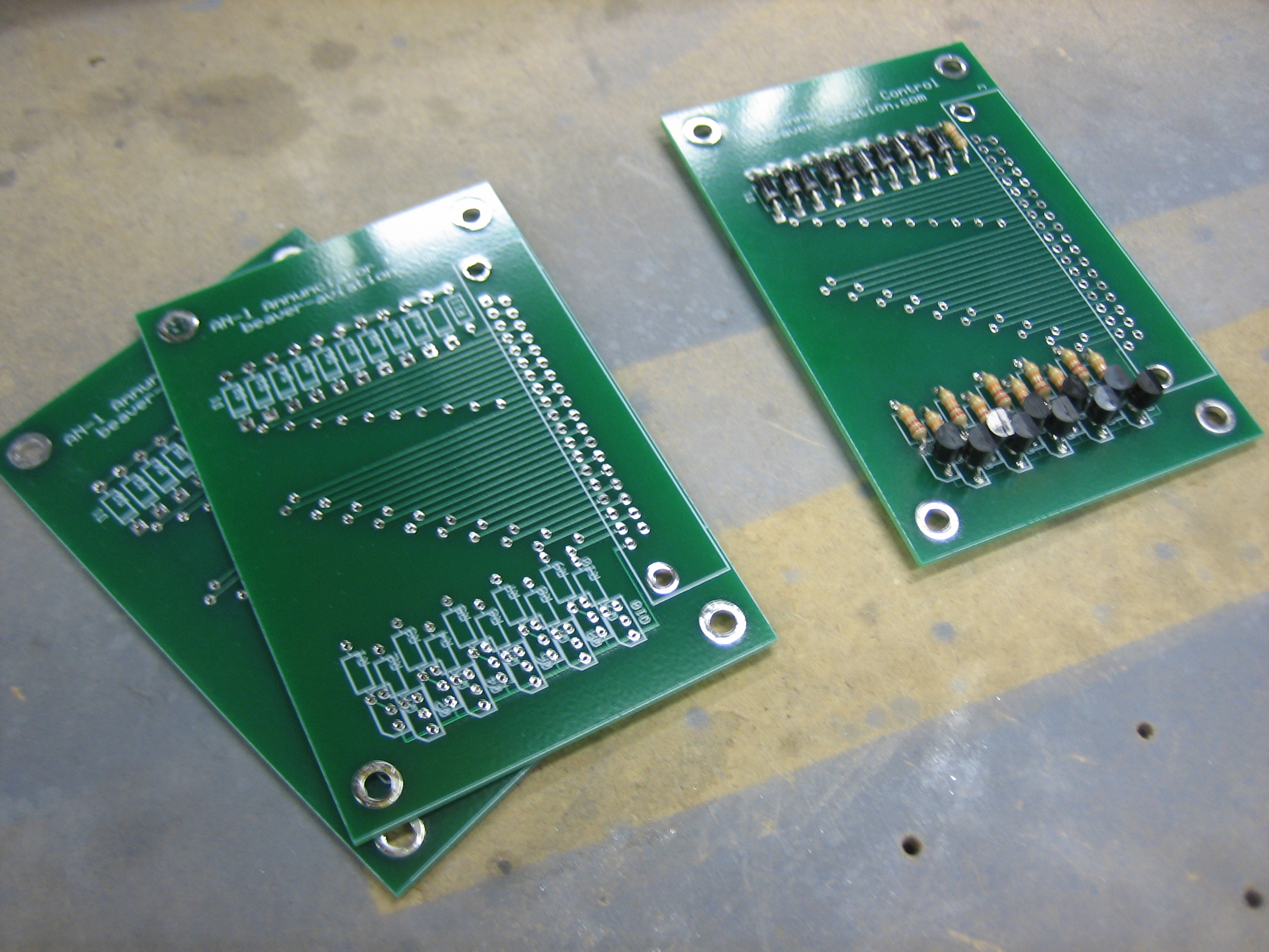
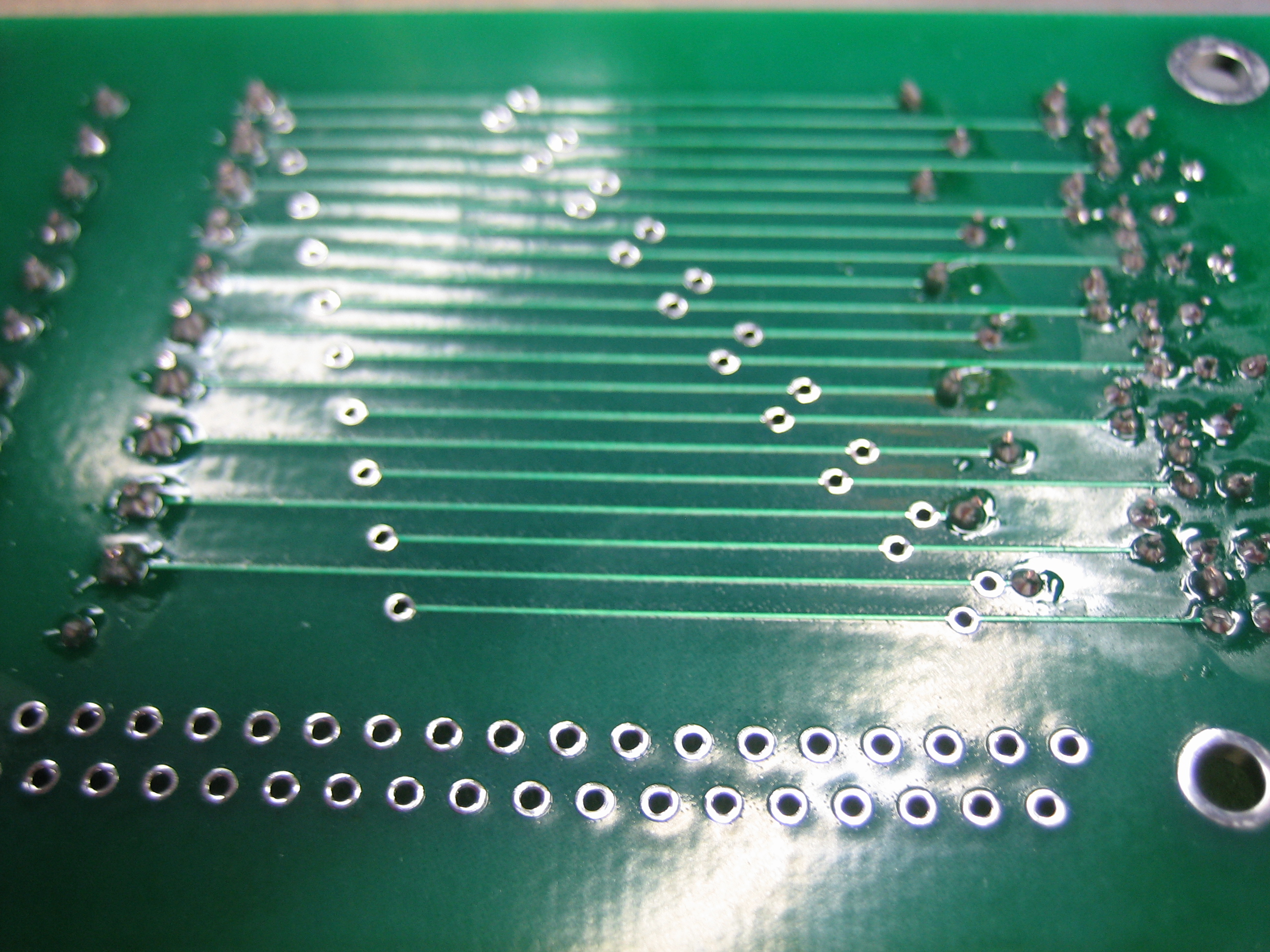
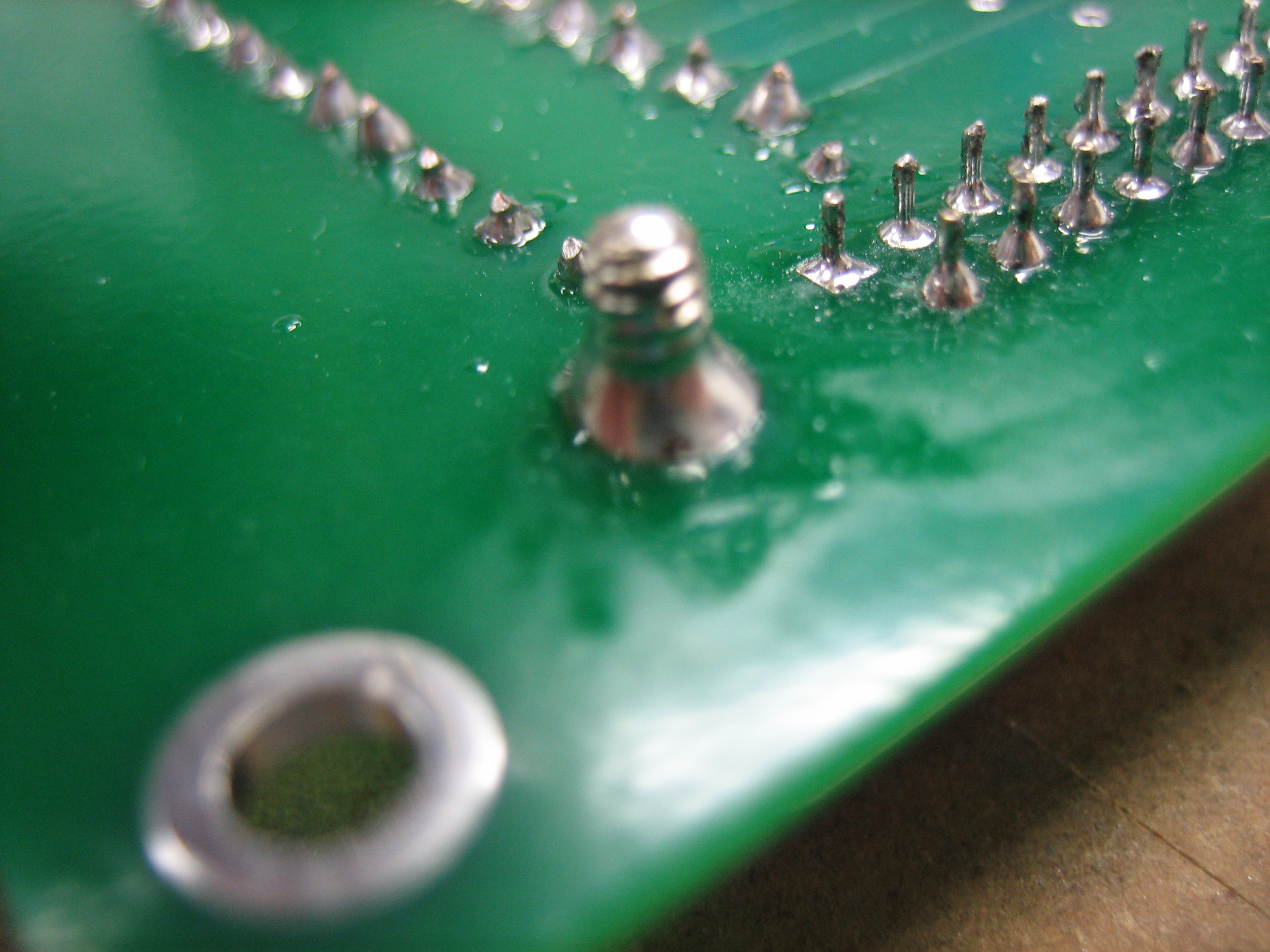
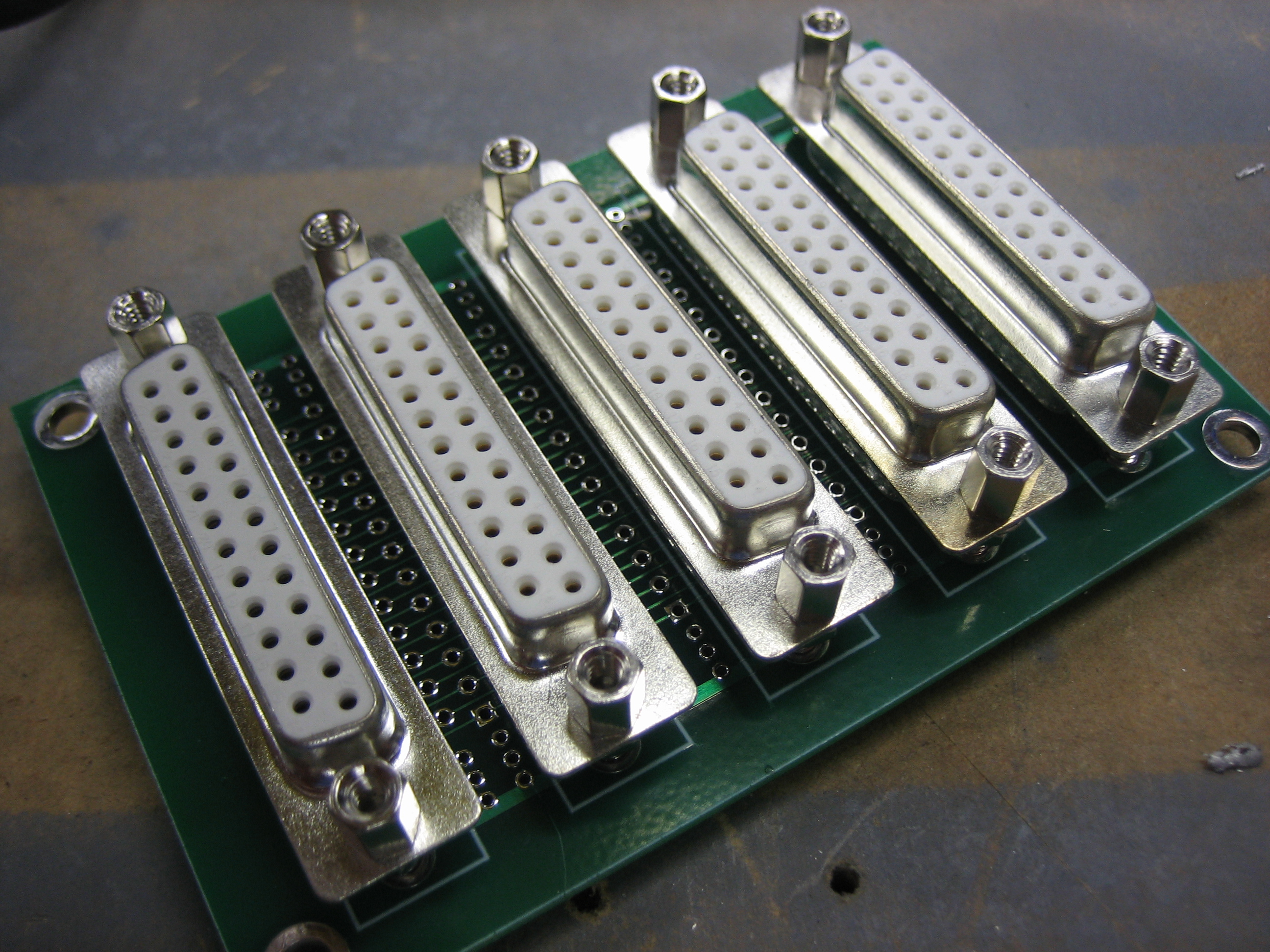
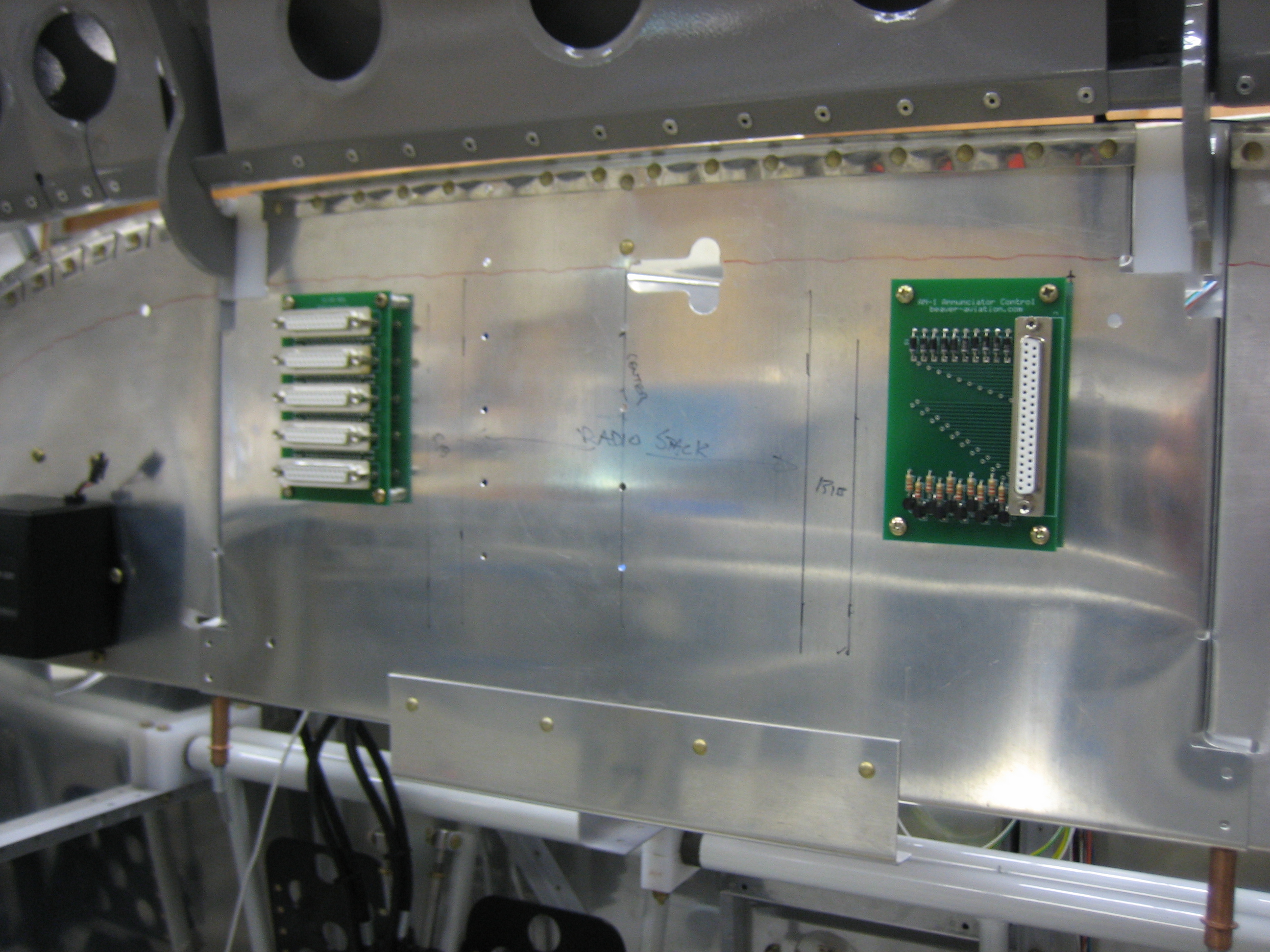
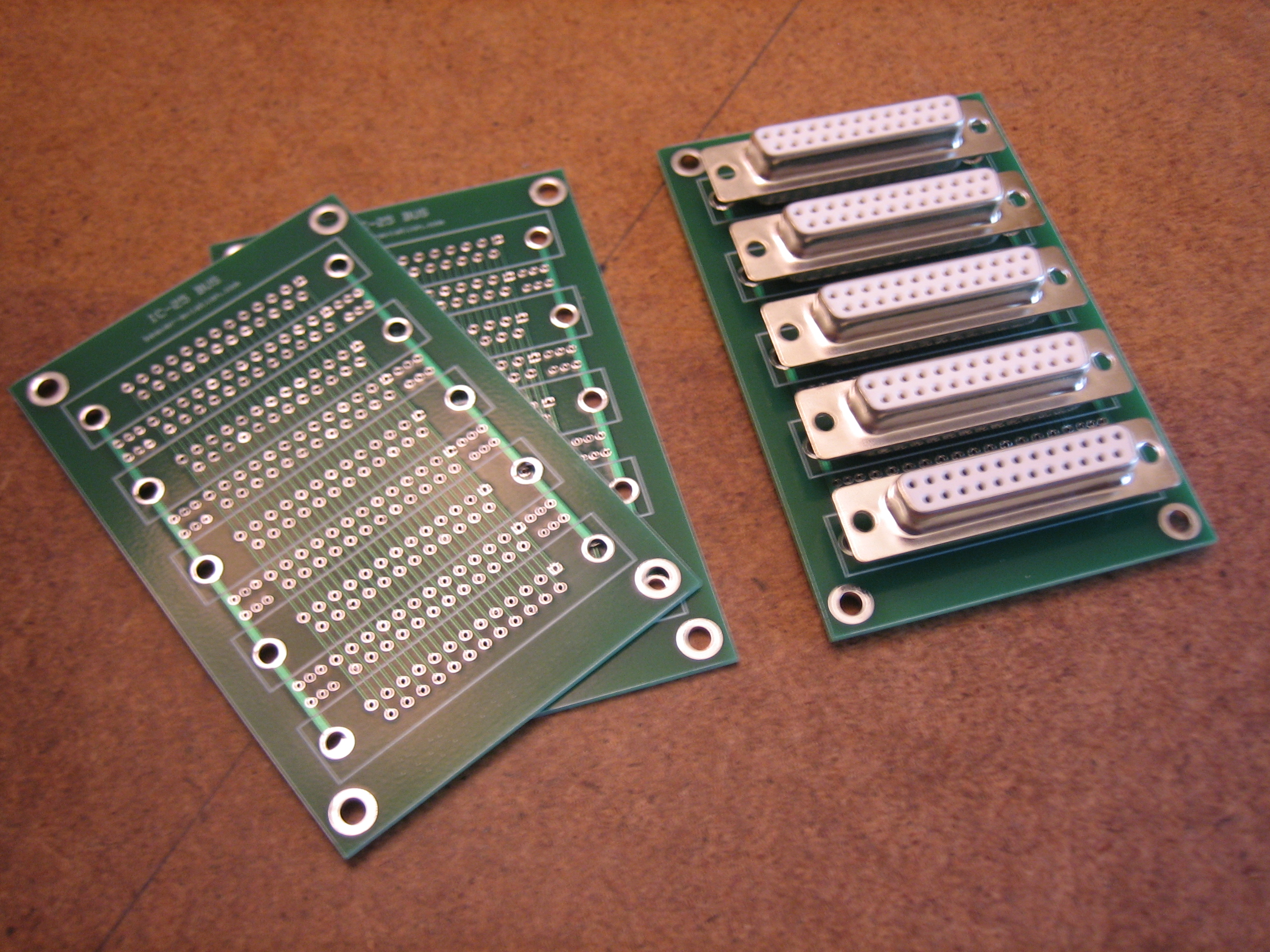
I received an order from ExpressPCB today with three PCBs that will be used to establish all of the interconnects between the avionics.  I installed 5 female DB-25 connectors in one of the boards, soldered the 125 contacts, and verified continuity between all the connectors.

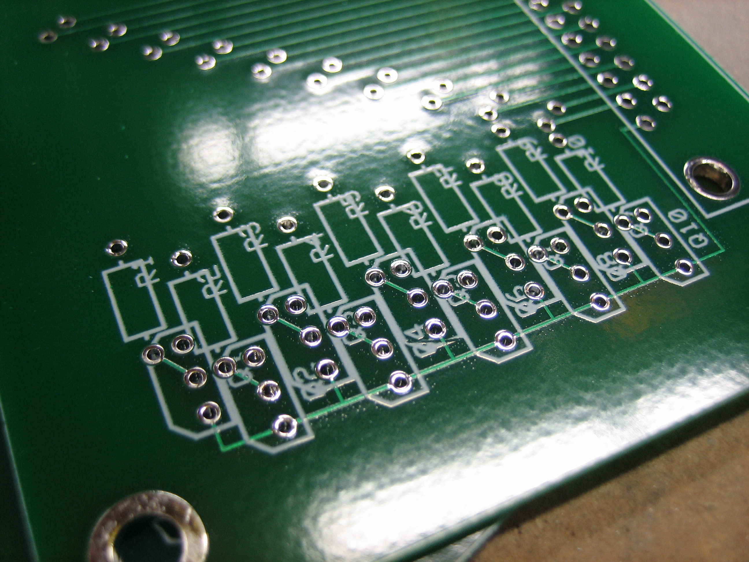
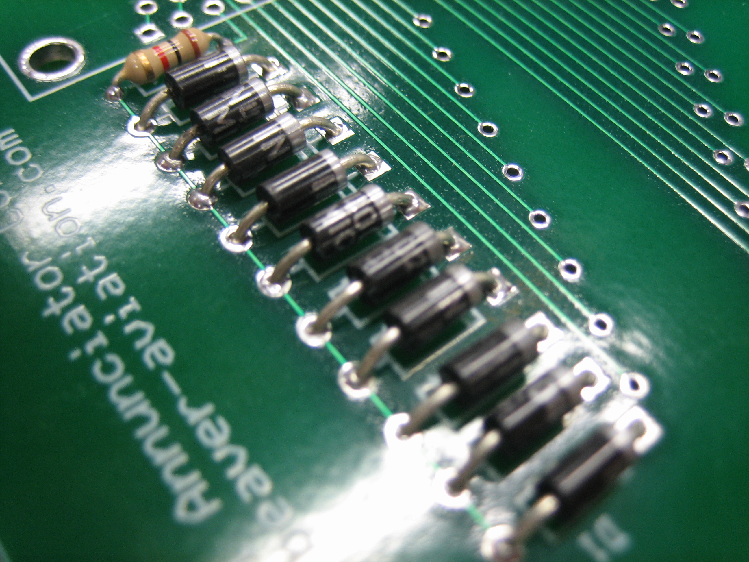
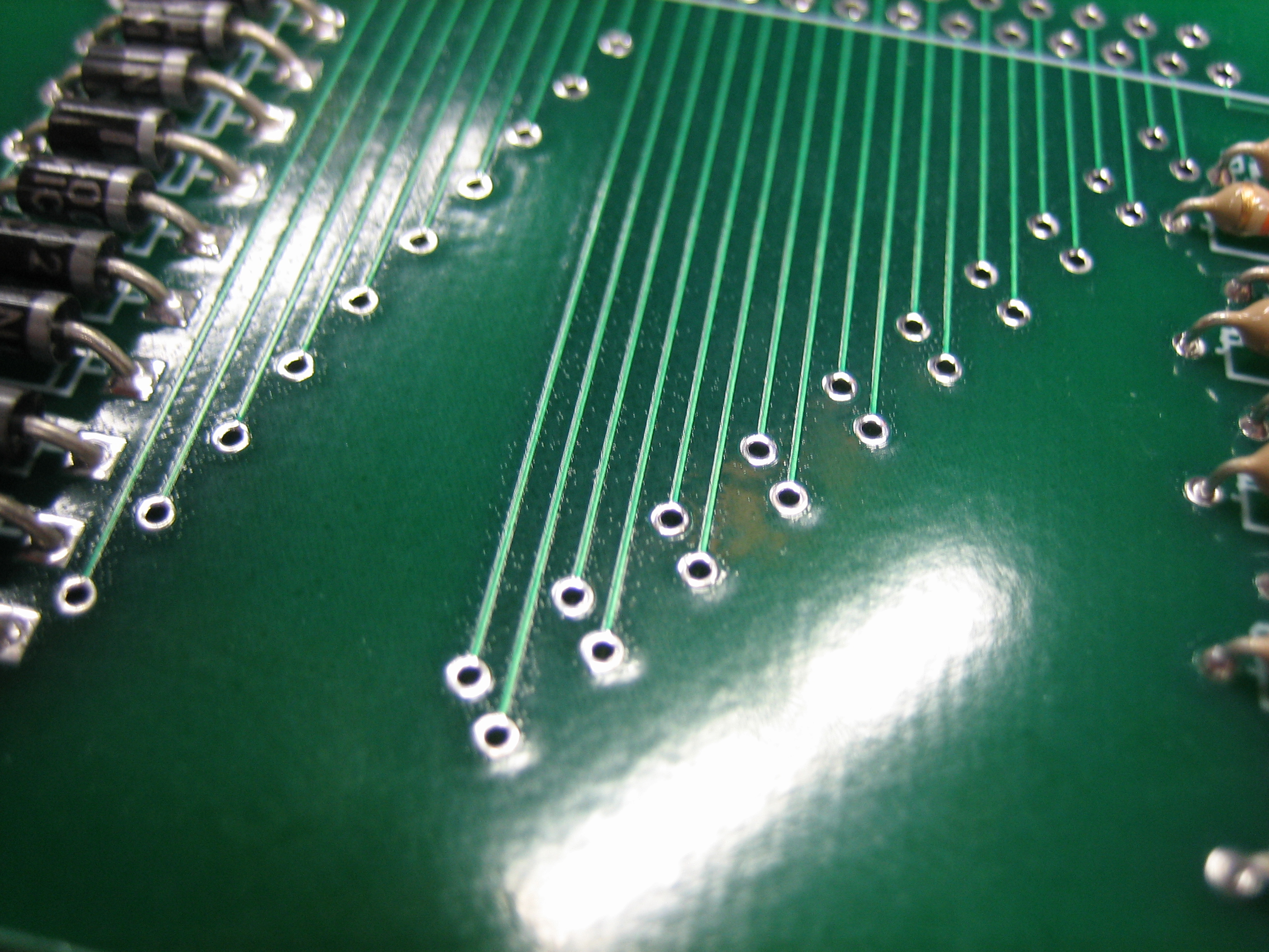
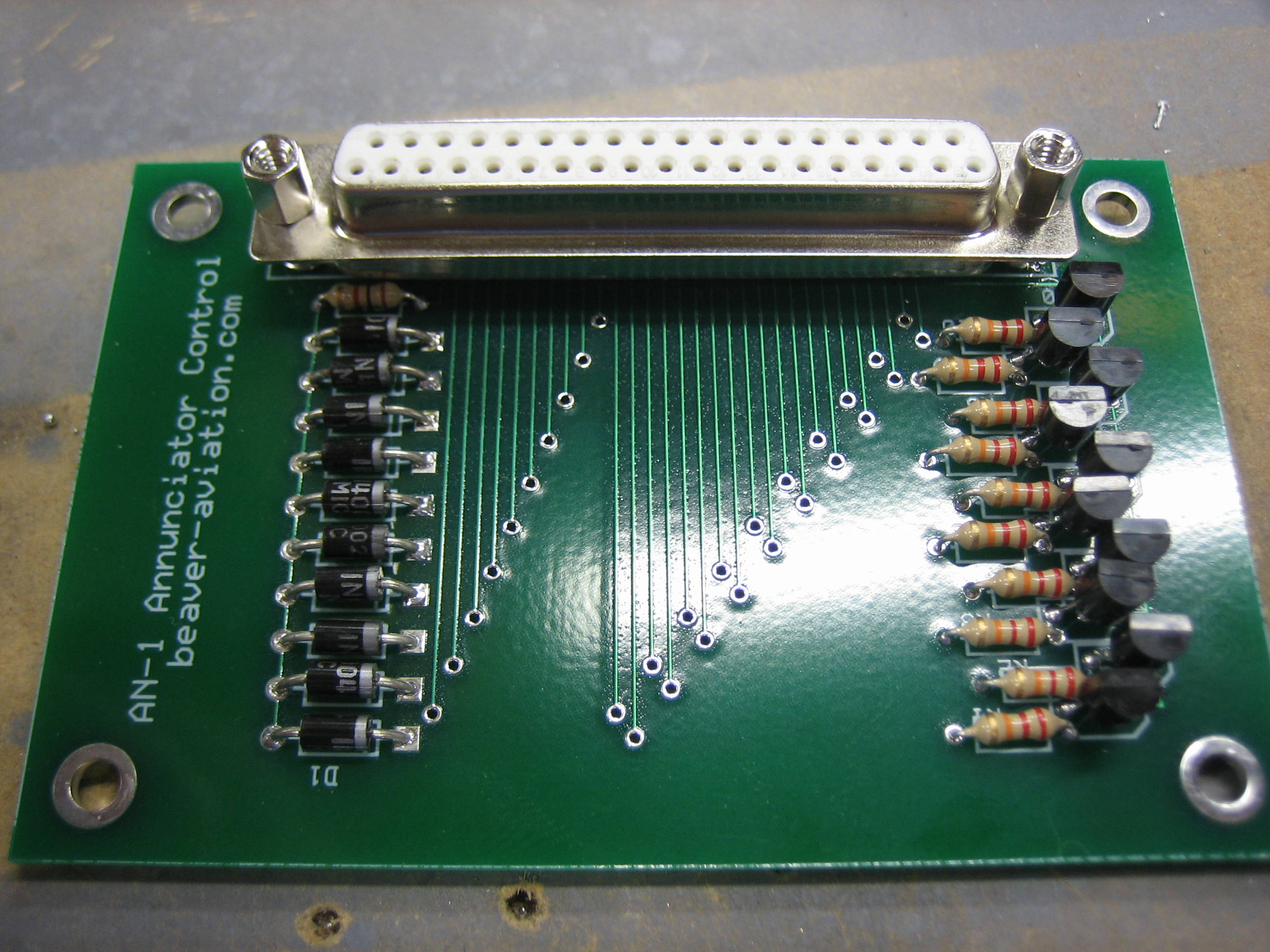
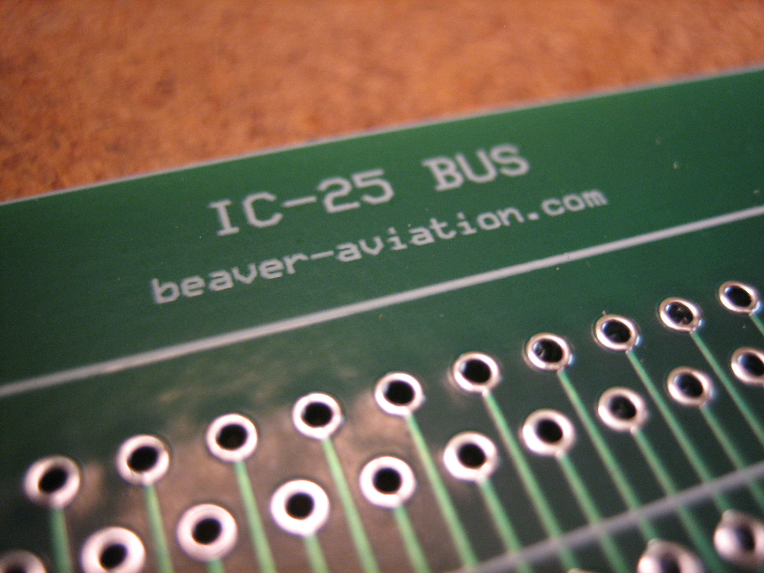
Here’s a closeup of one of the PCBs.  You can see that all of the DB-25 connectors are connected in parallel.  There are also extra solder pads between each connector in case there are components that need to connect various traces (e.g. resistors, diodes, etc.)  There are also even more extra pads off to the side that are unconnected that can be used for various purposes.  I don’t think I’ll need any of these features for my avionics interconnects, but I figured I’d add these in to make the PCB more flexible.

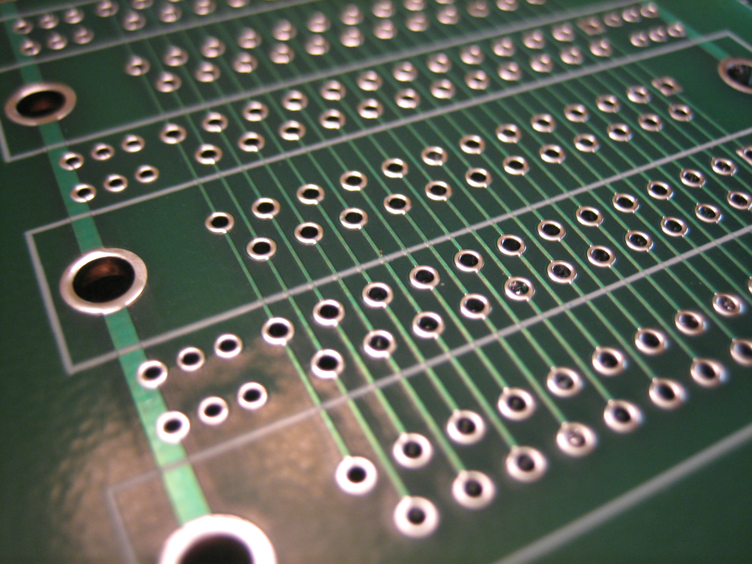
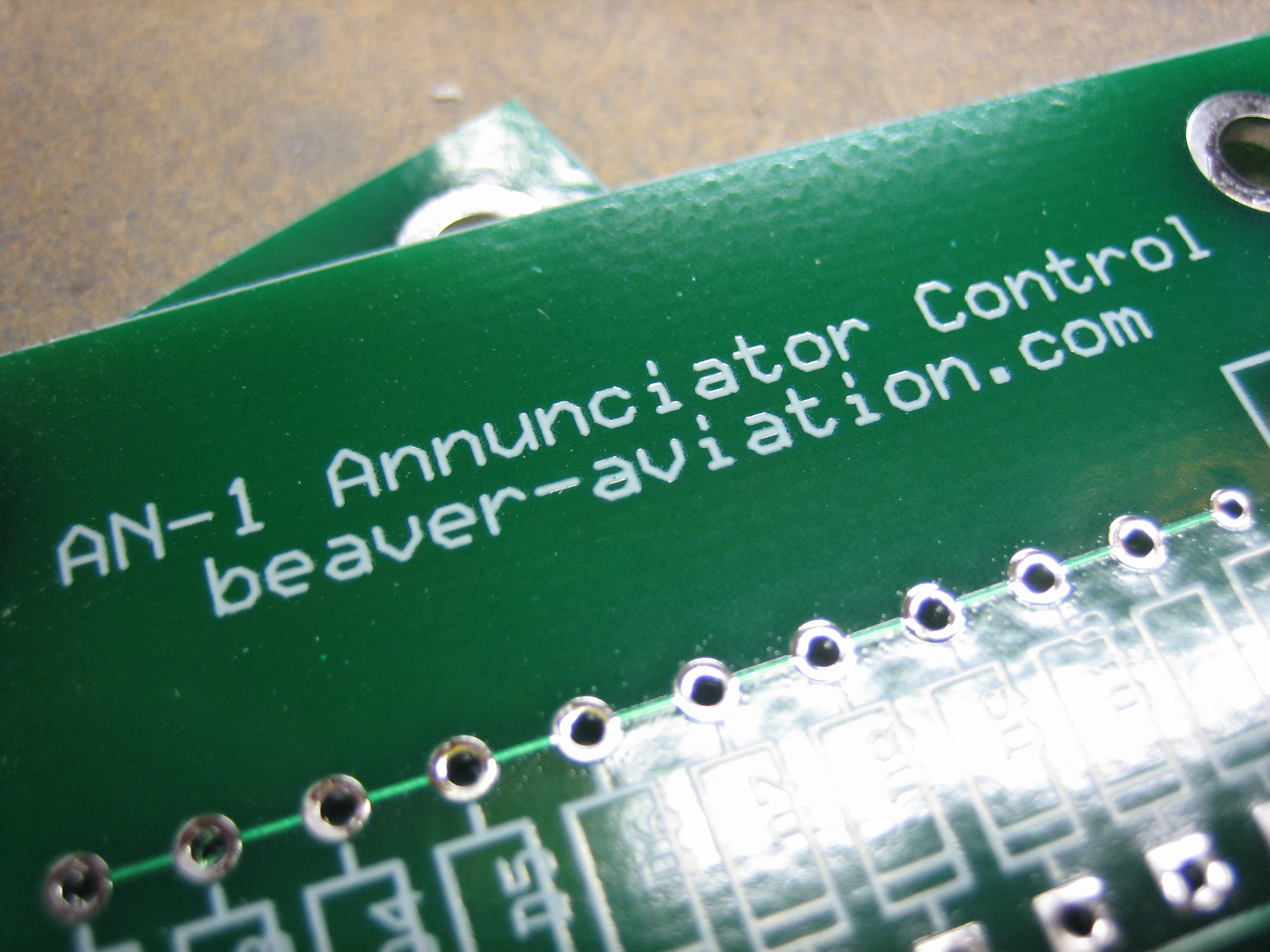
I figured I’d go ahead and name the circuit and throw a web address on there.  Since I ordered three, I have two extras for sale; let me know if you want one of them.  If there is enough demand, I may start offering these for sale.

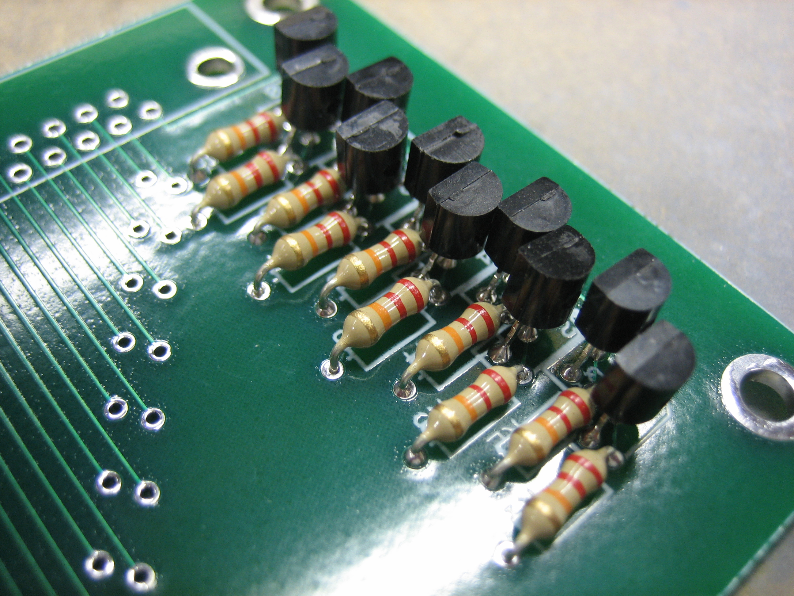
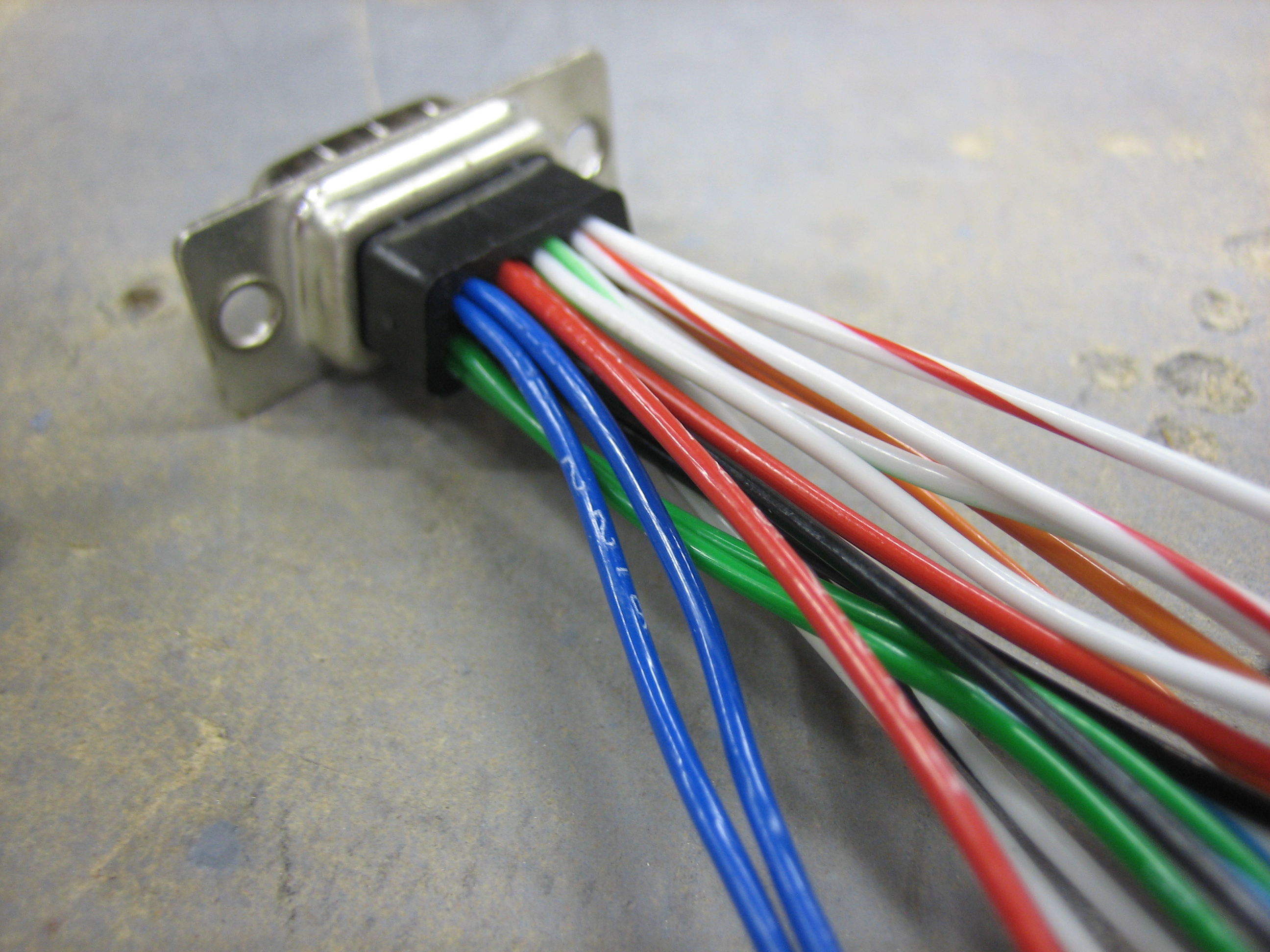
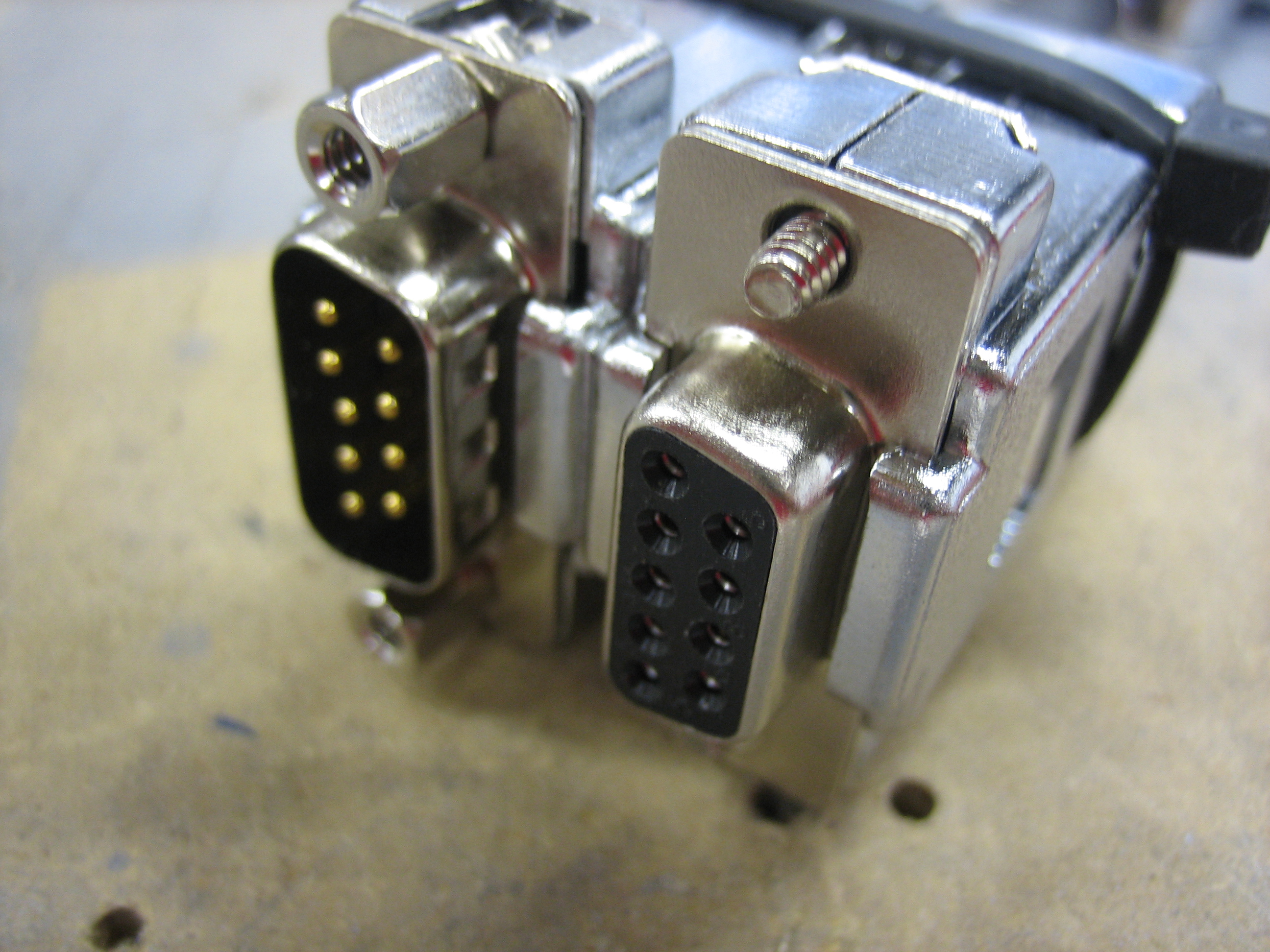
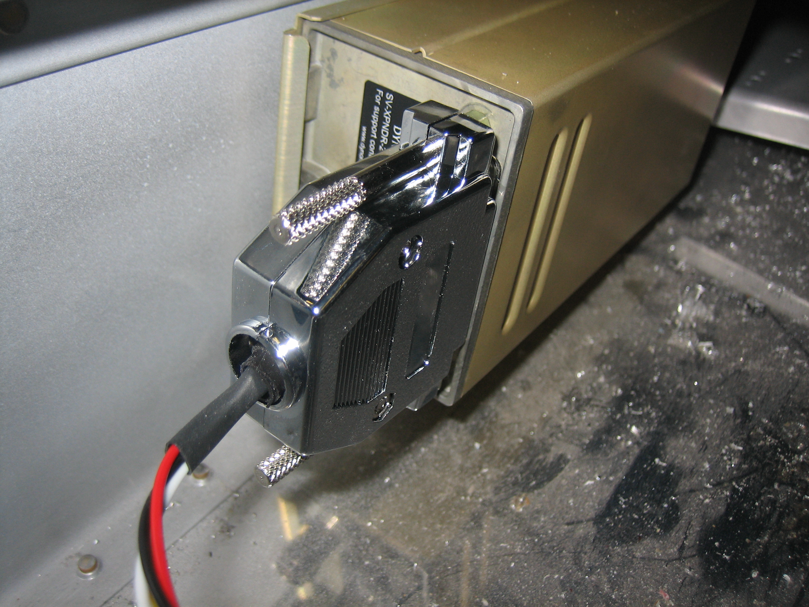
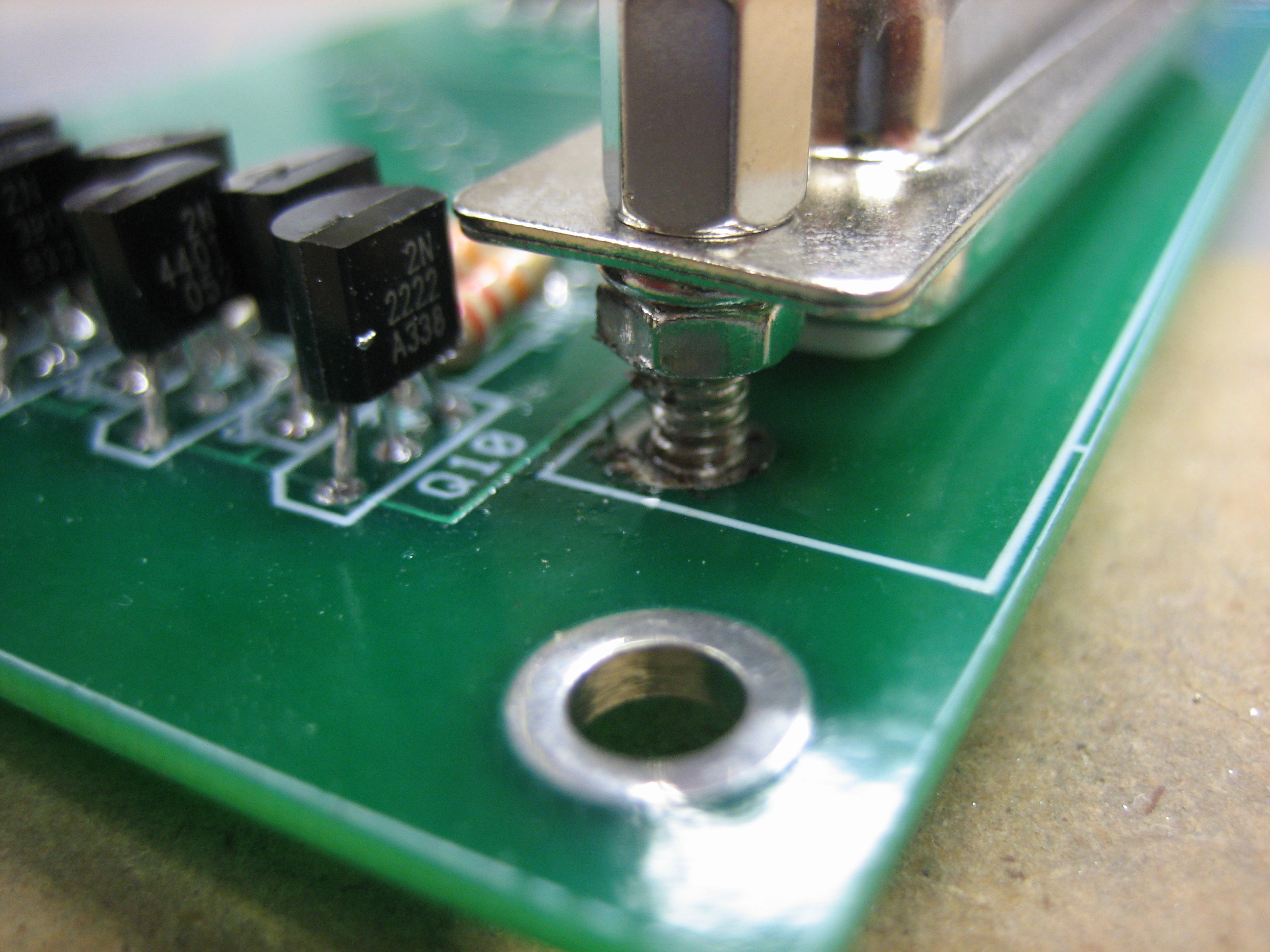
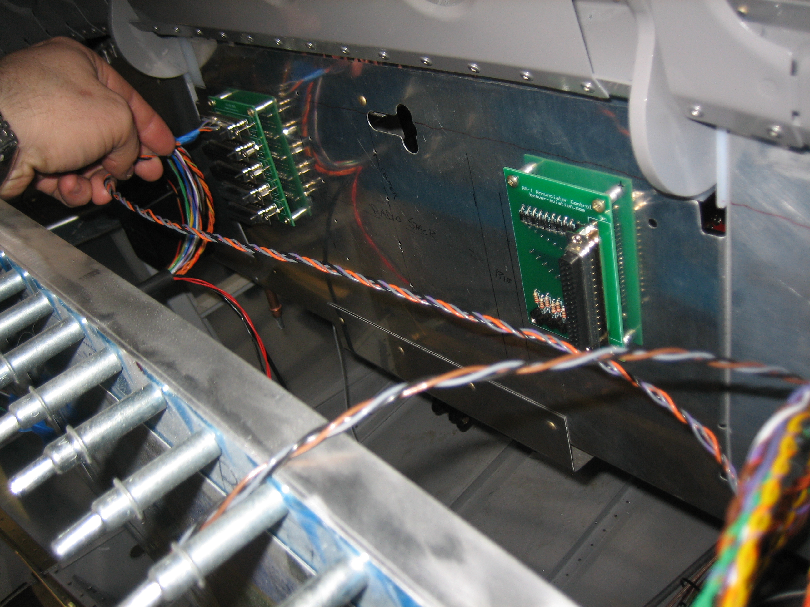
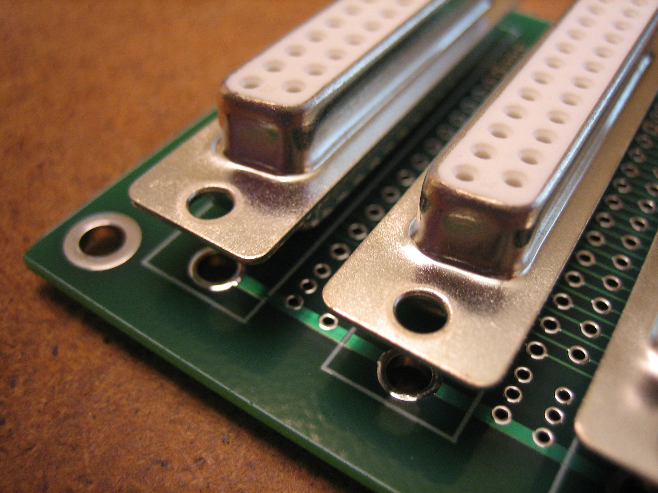
Here’s a closeup of the female DB-25 connectors.  I’ve got some 1/2″ jack screws on order that will be used to anchor the connectors more firmly to the PCB.

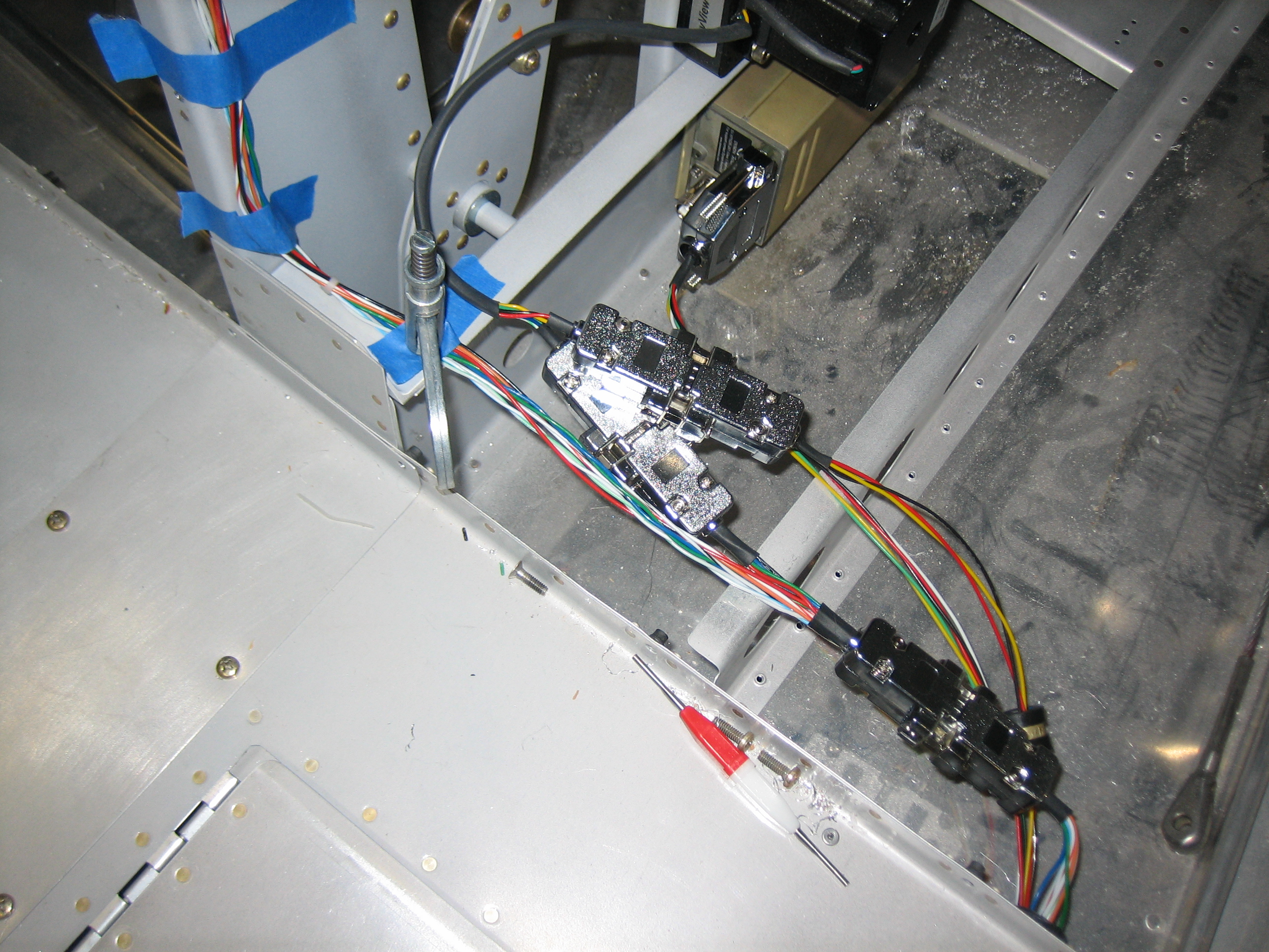
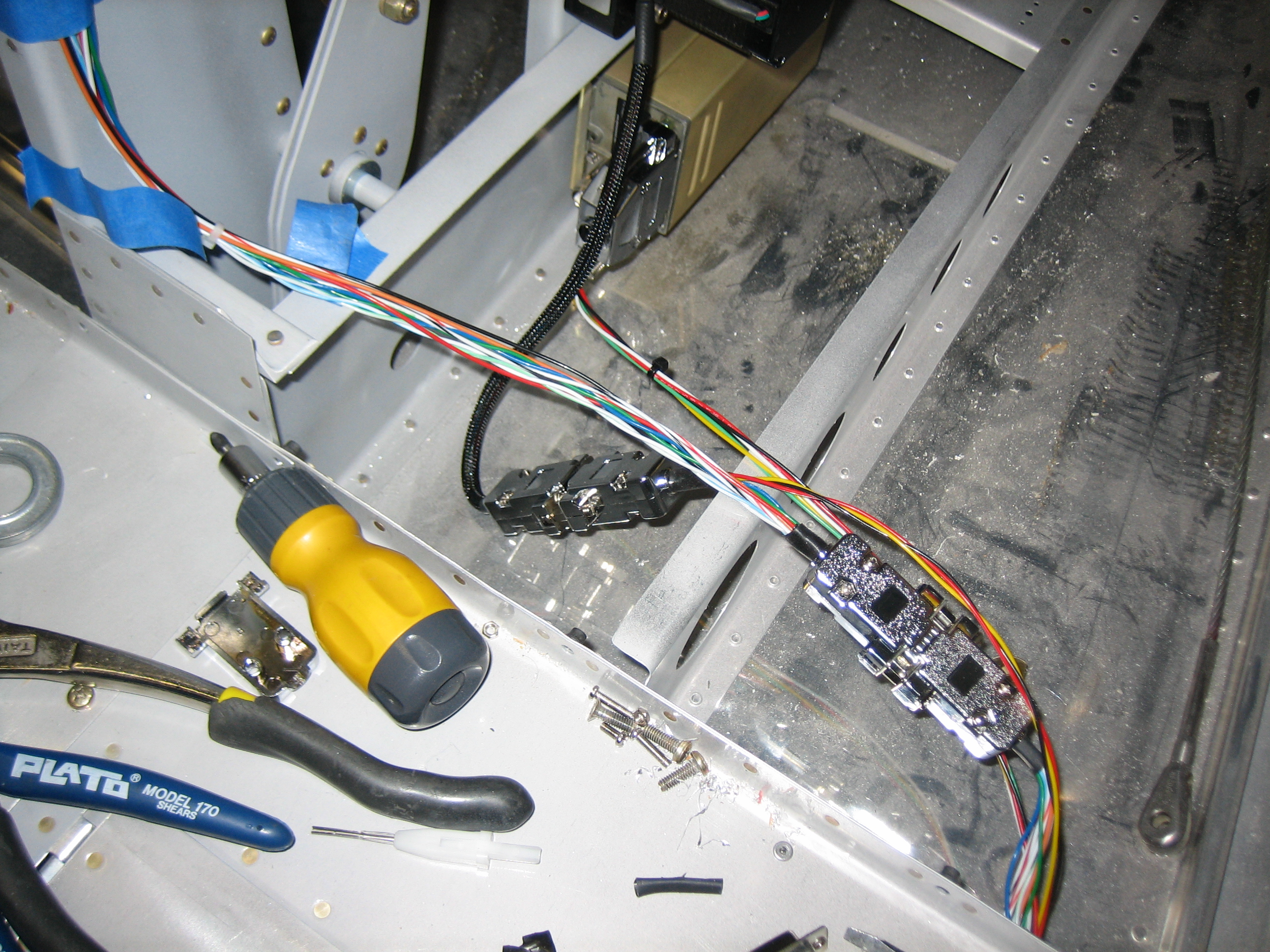
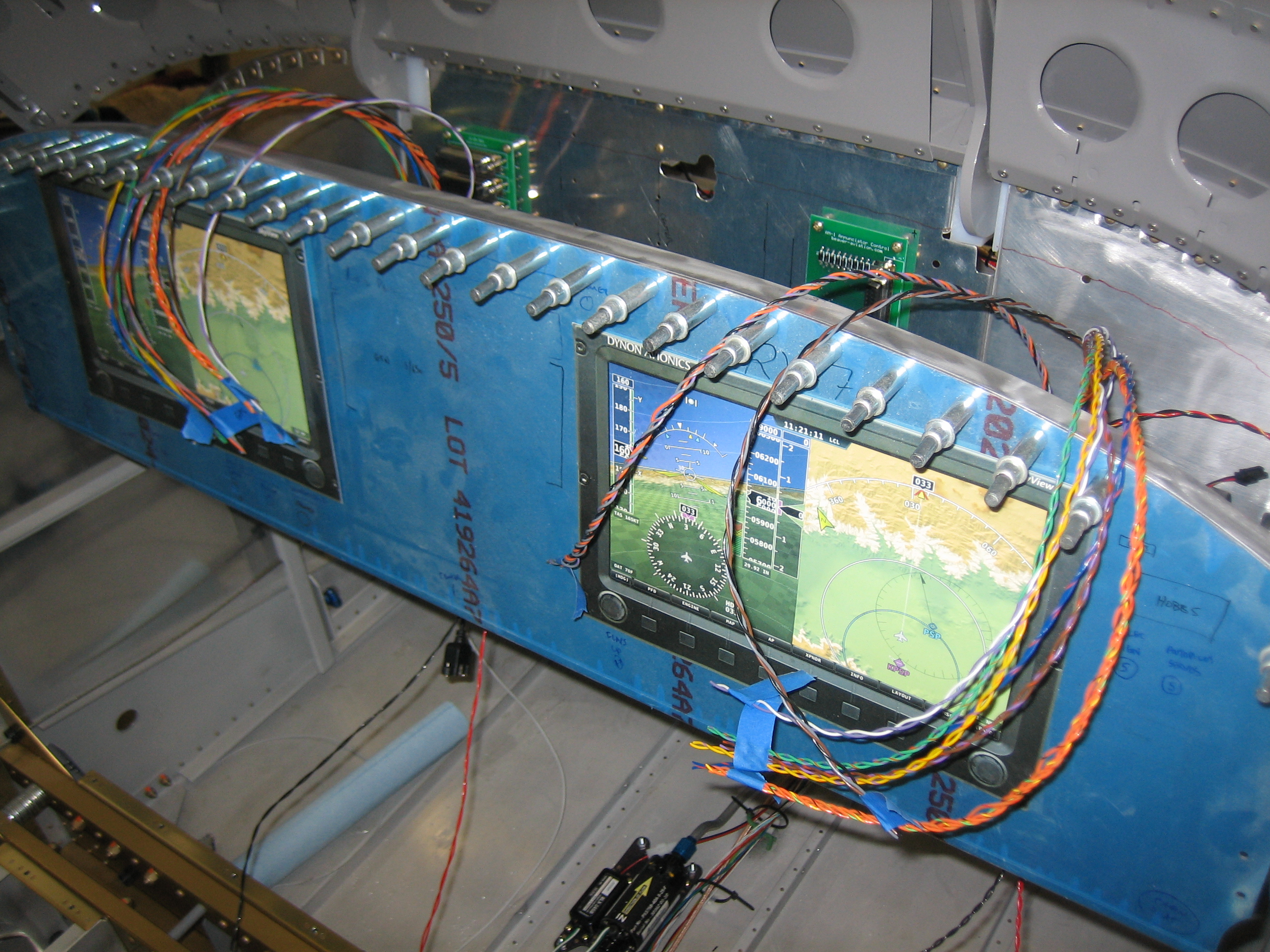
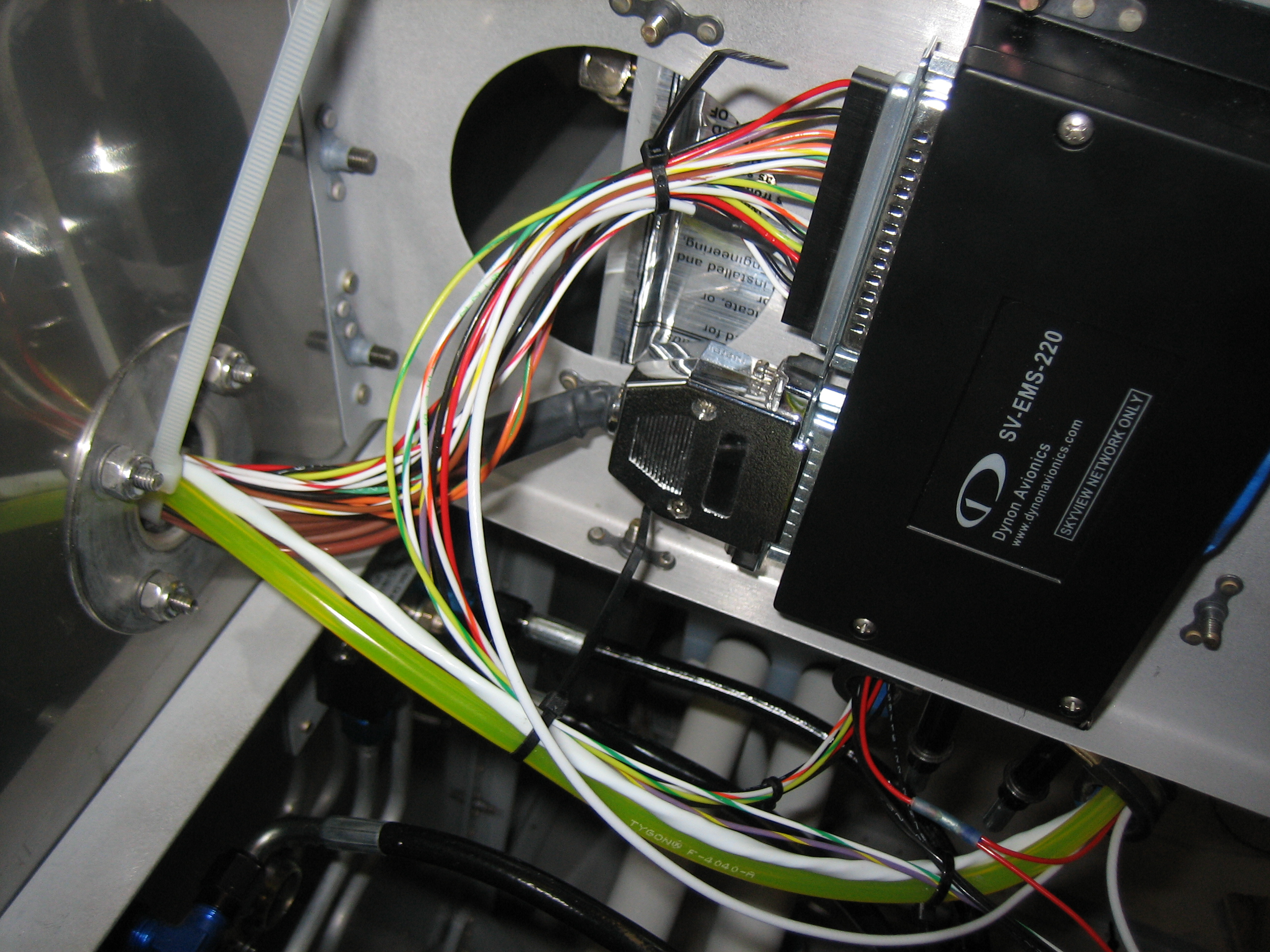
I’ll post a schematic later showing how these will be used, but the basic idea is that all of the serial and audio lines from the left SkyView screen will go to one connector and the serial and audio lines from the right SkyView screen will go to another connector (on the same pins since the SkyView requires they be connected together).  The serial lines from the Dynon transponder and GPS will go to a third connector (connected to the appropriate pins so that they can communicate with the SkyView screens).  The Garmin GTN-650 serial lines will go to a fourth connector to talk to both the SkyView screens and the transponder (to support the ADS-B out mandate).  The audio panel will connect to the final connector to get audio alerts from the SkyView and GTN.  I may also use this circuit to connect the dimming lines from all of the avionics.  This will be so much easier to wire and maintain than connecting all of the wires together directly in the harness.

Received Annunciator Control Circuits and Worked on Network Cables

I received my annunciator control boards from ExpressPCB.

Here’s a closeup of the driver end of the circuit board.  I had to stagger the parts to get everything to fit with enough clearance around all the solder pads.

Just like the Avionics Interconnect circuit from yesterday, I threw a part number and website on these in case I start selling them.  I’m definitely selling the other two, so email me if you want one.  These can drive up to 10 annunciator lights triggered by either 12V or ground and include a facility for a push to test function and an external dimmer.

Here’s the driver end of a populated board.  I don’t have the PCB mount DB-37 connector yet which is why that isn’t present.

Each annunciator light driver has an isolation diode to allow the push to test function.  The extra resistor is to protect the diodes against shorting one of the high triggers to ground.

I didn’t forget to attach components here, these are plated through holes that allow these traces to connect to traces on the other side of the board.

Here’s where those traces come through.  These route signals to the resistors driving the base of each transistor as well as the collector side of each transistor.  The emitters of all transistors are connected together and grounded.

I’m trying to wrap up the tailcone wiring before installing the rear window for good.  I fabricated a custom length SkyView network cable to go from the ADAHRS down to the pitch servo.  There will be a splitter mounted there that allows the ADAHRS and pitch servo connectors to join to the network cable that will be routed under the floor to the area under the pilot’s seat.  To fabricate the splitter, I cut two short sections of SkyView network cable and installed one end of both sets of wires into a single male DB-9 connector.  It’s pretty challenging, but you can install two 22AWG wires into a single crimp pin.  Getting all of the strands to slide into the pin before crimping is definitely a pain, but is doable.

Worked on Avionics Wiring

I prepped the wires for the transponder harness.  The white wire has a 1.2k? resistor inline.  The wires overlap the resistor on each side to support the resistor.  I added a layer of heat shrink over the resistor after I took this picture.

I added the wires to the transponder connector.  The red and black wires are power and ground respectively.  The green and yellow wires will connect to one of the SkyView serial ports.  The white wire (under the heat shrink) will connect to the serial TX line of the Garmin GTN-635 to provide location into to the transponder.

Here’s the connector attached to the transponder.  I’m generally avoiding using the thumb screws on DB connectors for weight reasons, but it would be pretty tricky to get a screwdriver on the lower screw, so I used them here.

I ended up deciding not to use the splitter I built yesterday since it ended up introducing extra connectors for no good reason.  I still ended up with 3 pair of DB-9 connectors since I split the servo power, ground, and Control Wheel Steering (CWS) line out into a separate connector.  I realized this was unnecessary, so I rewired this for the third time.

Now there are only two DB-9 connector pairs.  The SkyView network cable comes out of the conduit and into a female DB-9.  The male connector it attaches to splits out the two serial TX and RX lines into a second female DB-9 connector on the left.  The servo power, ground, and CWS lines come out of the conduit and also go into this connector.  Now there is only one male DB-9 for all of the servo attach wires.  The other wires coming out of the first male DB-9 connector (on the right) go up to the ADAHRS.

I added an adel clamp where the wires come out of the conduit to keep the wires from pulling on the conduit.

Here’s the next bay to the right (where the pilot’s stick goes.  There is a pair of DB-9 connectors here to provide another point for the network to split.  The red, black, and yellow wires are for the servo power, ground, and CWS wires.  The power and ground wires will connect here to another pair of wires that will run forward to the VP-X and ground block.  The yellow wires will connect together and go the CWS button on the pilot’s stick.

I also used the thumb screws here since it would be a pain to get a screwdriver on these screws.

The next bay to the right of that contains the two output connectors for the splitter in the previous bay.  I used one male and one female connector here since these aren’t electrically identical.  The male connector is a standard SkyView network connector and it is connected to a cable that runs up behind the instrument panel.  The other side of the splitter (the currently unconnected female DB-9 connector) only contains the two serial TX and RX lines as well as the servo power, ground, and CWS lines.  Another connector will attach here and go out to the right wing to hook up to the roll servo.

I also added another adel clamp to help stabilize the wires where they cross under the elevator push tube.

I hooked up the transponder power and ground wires.  You can also see the yellow, green, and white serial lines as well as the SkyView network cable routed through here.

Installed Cable to Roll Servo

I fabricated and installed the cable to the roll servo in the right wing and hooked it up under the pilot’s seat.

I ran the wire under the passenger seat and coiled the wire in the outboard bay.  I’ll drill the hole and then pull this out to the servo when the wings are attached permanently (or add a connector in the wing root; I haven’t decided).  I previously ran some servo wire in the wing that I bought from SteinAir, but I’m going to swap that out for the harness wire I purchased from Dynon.  I’d like to keep all network wires the same color throughout the aircraft so that it’s easier to maintain things down the road.

Installed Remaining Connectors on PCBs

I received an order from L-Com today with a bunch of additional connectors, shells, etc.  I installed the female DB-37 onto the annunciator control board.  After installing this, I hooked up a couple of annunciator lights and the dimmer and verified I could trigger the lights on both high and low signals as well as verified that accidentally grounding the high trigger or putting +12V on the low trigger had no effect.  Everything tested out perfectly.

I also installed some longer jack screws in the connector.

I soldered the other side of the jack screws to the circuit board to provide some additional support to the connector.  This thing is very strong now.

I also installed jack screws in the avionics interconnect circuit and soldered them to the board.  These circuits are ready to install.

Worked on Power Wiring

I got an order from Aircraft Spruce today with some 6AWG wire, so I fabricated the wire from the output side of the alternator current limiter to the Vertical Power VP-X.  Here’s the alternator current limiter end of the wire (protected by the boot).  All of this metal down here is hot when the master contactor is closed.  I need to research if it is necessary to shield all of this in case something were to inadvertently connect any of this to ground.

Here’s how the wire is routed up to the firewall pass-through.  You can see that the wire to the battery bus (the one that forms a U shape right in the center of the picture) also follows this wire up.  Behind the VP-X wire is also the alternator field wire.  I’ll be installing a few more adel clamps and some high-temp zip-ties (replacing the cheap zip-ties currently installed).

Here’s where the main VP-X wire comes through the firewall and drops down under the subpanel support rib through an additional adel clamp I installed just for that wire.  Being 6AWG, it’s fairly heavy (especially when pulling 6 Gs), so I want it well supported.  You can also see that I installed the main battery bus with some hardware that also showed up from ACS and connected the battery bus supply wire.  You can also see the alternator field wire (the small white wire in the upper right) has been cut and connected to the voltage regulator.  Finally, I connected the voltage regulator ground wire (the black wire in the upper right.  I could have taken a short-cut through the rib lightening hole and made the wire substantially shorter, but I’m trying to keep all the wire bundles neat and organized instead of running them haphazardly around the plane.

The VP-X supply wire has a short straight shot from the bottom of the subpanel support rib to the VP-X power post.  I installed a boot on this end of the wire as well.

Wiring Voltage Regulator and SkyView

I wired up the voltage regulator (except for the wire going to the annunciator control circuit for the low voltage light).

The two power lines (red) are connected to separate pins on the VP-X.  The larger (18AWG) wire on the top provides power for the alternator field.  The voltage regulator takes power from this wire and sends it out the white wire to regulate the alternator.

I installed the second SkyView battery on the right side in the same spot as the one on the left.

I also laid out when the radios will penetrate the subpanel, then installed the custom circuits on either side of that.  The IC-25 Bus is on the left and the AN-1 Annunciator Control circuit is on the right.

I fabricated 1/4″ aluminum spacers to keep the back of the circuits from contacting the subpanel.

I measured where the SkyView connectors will sit on the back of the panel and taped them in place so that I could start wiring them.

I separated out all of the wires and labeled them.

All of the wires from the right SkyView display that need to connect to the bus will reach across the panel.  They will need to be run across the top of the audio panel and through the two panel support ribs.  I can’t run any of these now since I don’t have the radio stack yet.

Installed Princeton Capacitive Fuel Senders

I received my capacitive fuel senders from Princeton Electronics.  They don’t have a website, but you can reach them at (616) 243-8800.  They have both 2 level and 5 level senders.  Both convert the capacitance range from 0-5 volts, but the 2S model only has calibration points for empty and full.  The 5S model has three intermediate points which is important if you want a linear movement on an analog gauge.  Since I’m using the SkyView which has numerous intermediate calibration points, it doesn’t matter if the sender is linear or not, so I’m just using the 2S sender.  I cut most of the wires off and installed some four position molex connectors on each sender so that they can be easily removed if necessary (well, except for the cable with the BNC connector).

I installed the senders on the aft side of the subpanel since they need to be accessed during calibration.  This is the left sender.

The right one is in the same relative position.

The cable to the fuel tank will get routed down the vent line, but I’m leaving it loose for now until I nail down the overall routing.

I drilled 1/4″ holes just above the vent bulkhead fitting and ran the cable with the BNC connector out through it.  This will get connected to the BNC fitting on the fuel tank which is wired up to the capacitive plates inside the tank.

Wired Up Fuel Senders and Finished EMS Wiring

I finished up the fuel sender wiring by running some wires from the other side of the molex connector.  The red and black wires go to power (VP-X) and ground respectively.  The striped wire is the included wire from the EMS running directly from the necessary pin.

I’m using a single pin on the VP-X (J8 connector) to power both senders.  The wire comes out of the connector and through the adel clamp on the right.  I then used a solder sleeve to split this wire into two: one that runs directly forward to the left fuel sender and one that goes through the left adel clamp and across the plane to the right fuel sender.

I grounded the two fuel senders as well as both SkyView screens (the two twisted pairs of the wires).  I’m down to 11 available spots on my grounding block which seems pretty tight.

I was down to just a handful of unconnected wires on the EMS, so I decided to finish that off tonight.  Two of the wires ran to the fuel senders.  One more ran over to the annunciator control circuit (not connected yet).  Another ran forward and will connect to the left ignition switch to get an RPM reading from the magneto.  Finally, I hooked up the low voltage RPM pins to the Lightspeed Ignition to get a second RPM source.

Here’s a closeup of the Lightspeed Tach line coming into the DB-37 connector.  It’s a shielded 22AWG wire.  I split the shielding out and put heat shrink over it and the split point and wired the center conductor to pin 35 and the shield to pin 16.