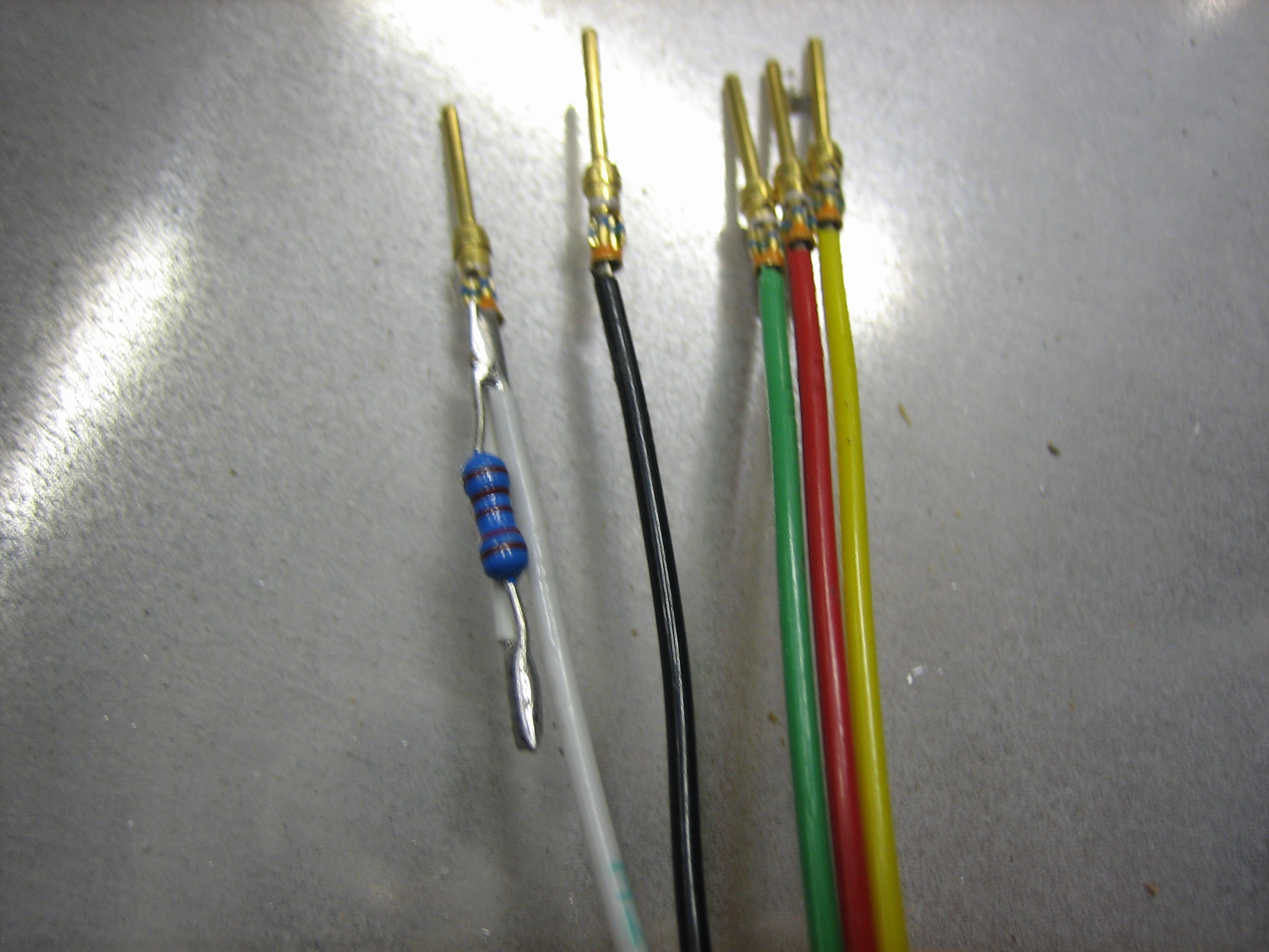
I prepped the wires for the transponder harness. The white wire has a 1.2k? resistor inline. The wires overlap the resistor on each side to support the resistor. I added a layer of heat shrink over the resistor after I took this picture.
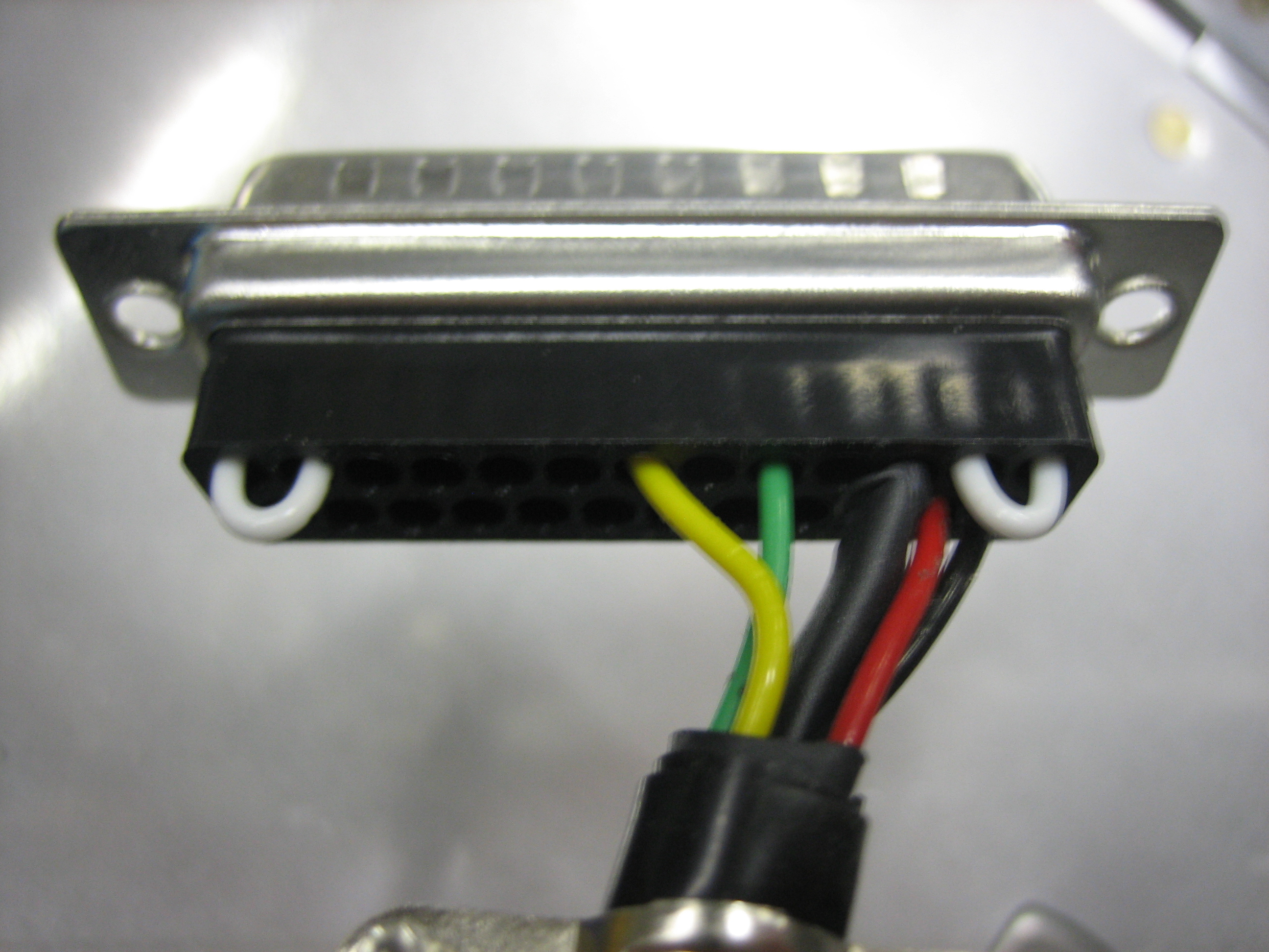
I added the wires to the transponder connector. The red and black wires are power and ground respectively. The green and yellow wires will connect to one of the SkyView serial ports. The white wire (under the heat shrink) will connect to the serial TX line of the Garmin GTN-635 to provide location into to the transponder.
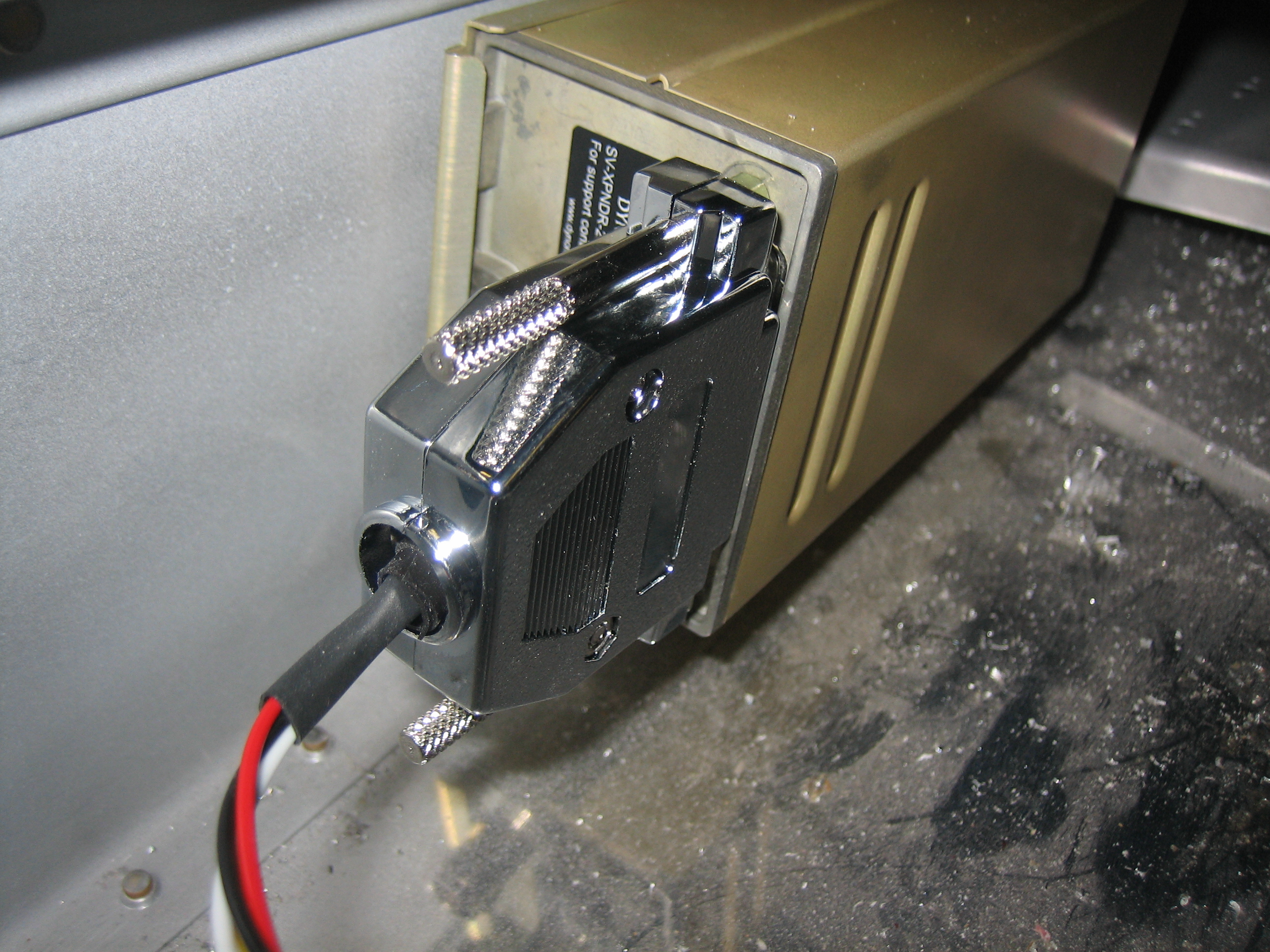
Here’s the connector attached to the transponder. I’m generally avoiding using the thumb screws on DB connectors for weight reasons, but it would be pretty tricky to get a screwdriver on the lower screw, so I used them here.
I ended up deciding not to use the splitter I built yesterday since it ended up introducing extra connectors for no good reason. I still ended up with 3 pair of DB-9 connectors since I split the servo power, ground, and Control Wheel Steering (CWS) line out into a separate connector. I realized this was unnecessary, so I rewired this for the third time.
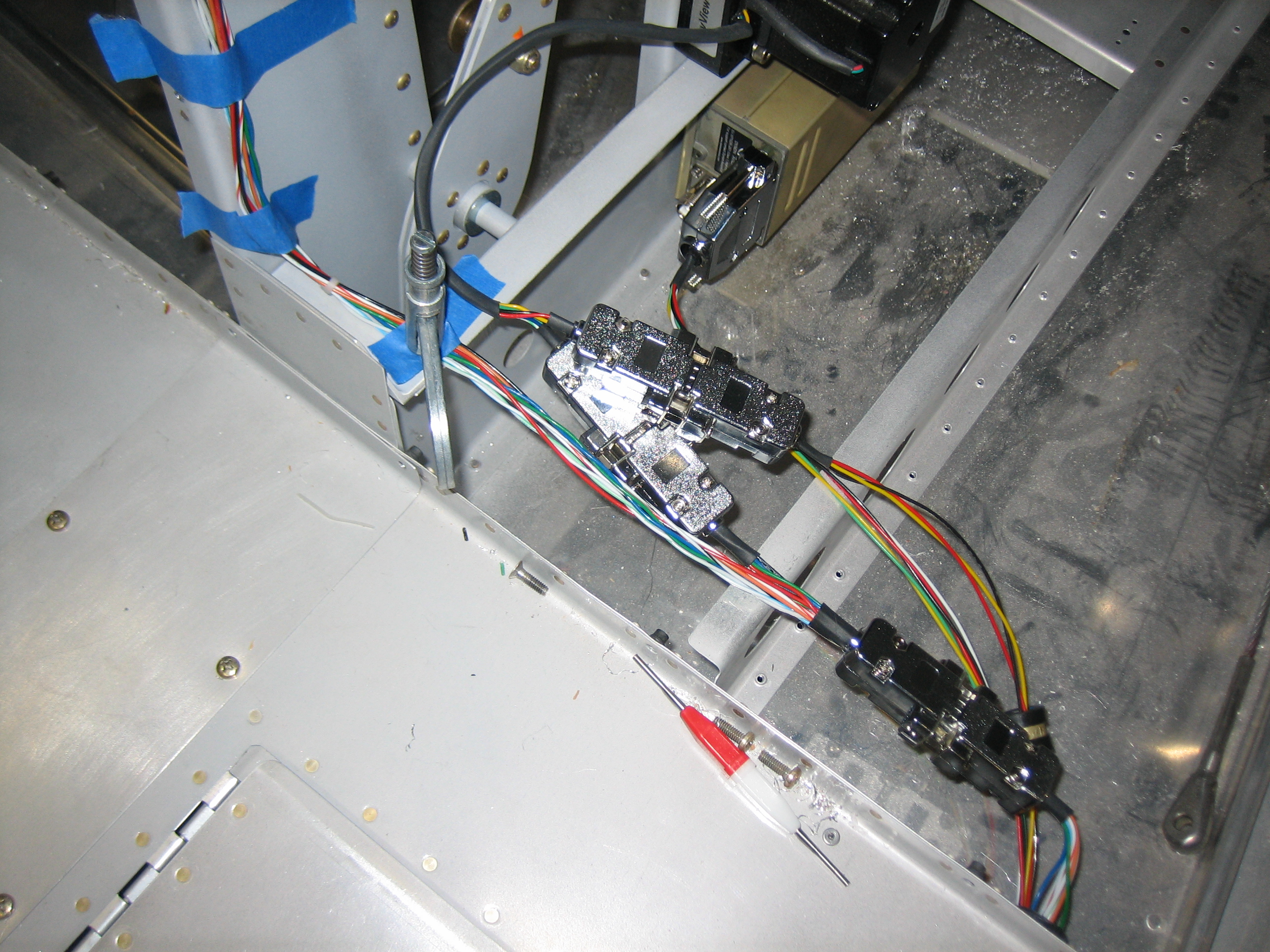
Now there are only two DB-9 connector pairs. The SkyView network cable comes out of the conduit and into a female DB-9. The male connector it attaches to splits out the two serial TX and RX lines into a second female DB-9 connector on the left. The servo power, ground, and CWS lines come out of the conduit and also go into this connector. Now there is only one male DB-9 for all of the servo attach wires. The other wires coming out of the first male DB-9 connector (on the right) go up to the ADAHRS.
I added an adel clamp where the wires come out of the conduit to keep the wires from pulling on the conduit.

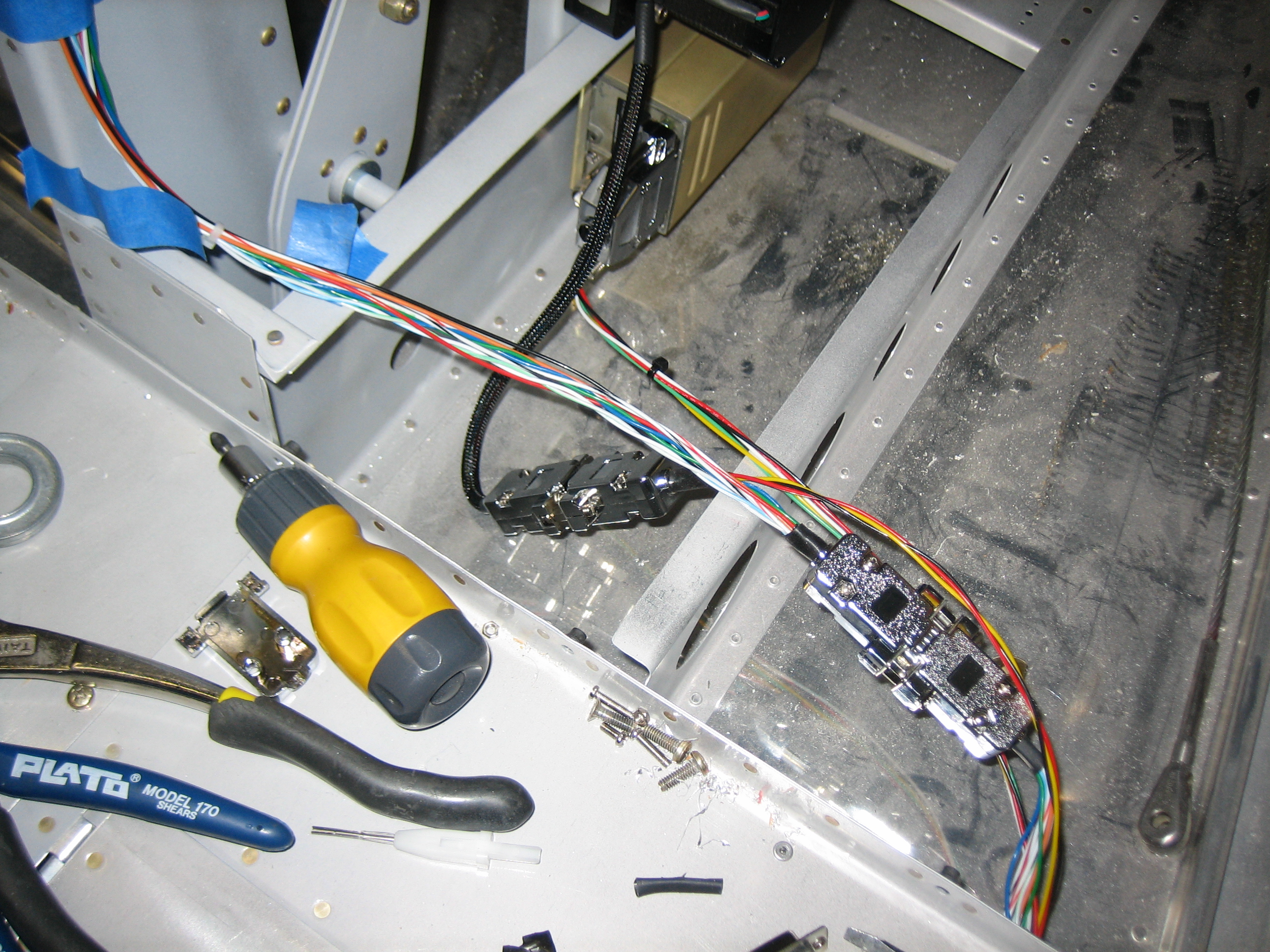
Here’s the next bay to the right (where the pilot’s stick goes. There is a pair of DB-9 connectors here to provide another point for the network to split. The red, black, and yellow wires are for the servo power, ground, and CWS wires. The power and ground wires will connect here to another pair of wires that will run forward to the VP-X and ground block. The yellow wires will connect together and go the CWS button on the pilot’s stick.
I also used the thumb screws here since it would be a pain to get a screwdriver on these screws.
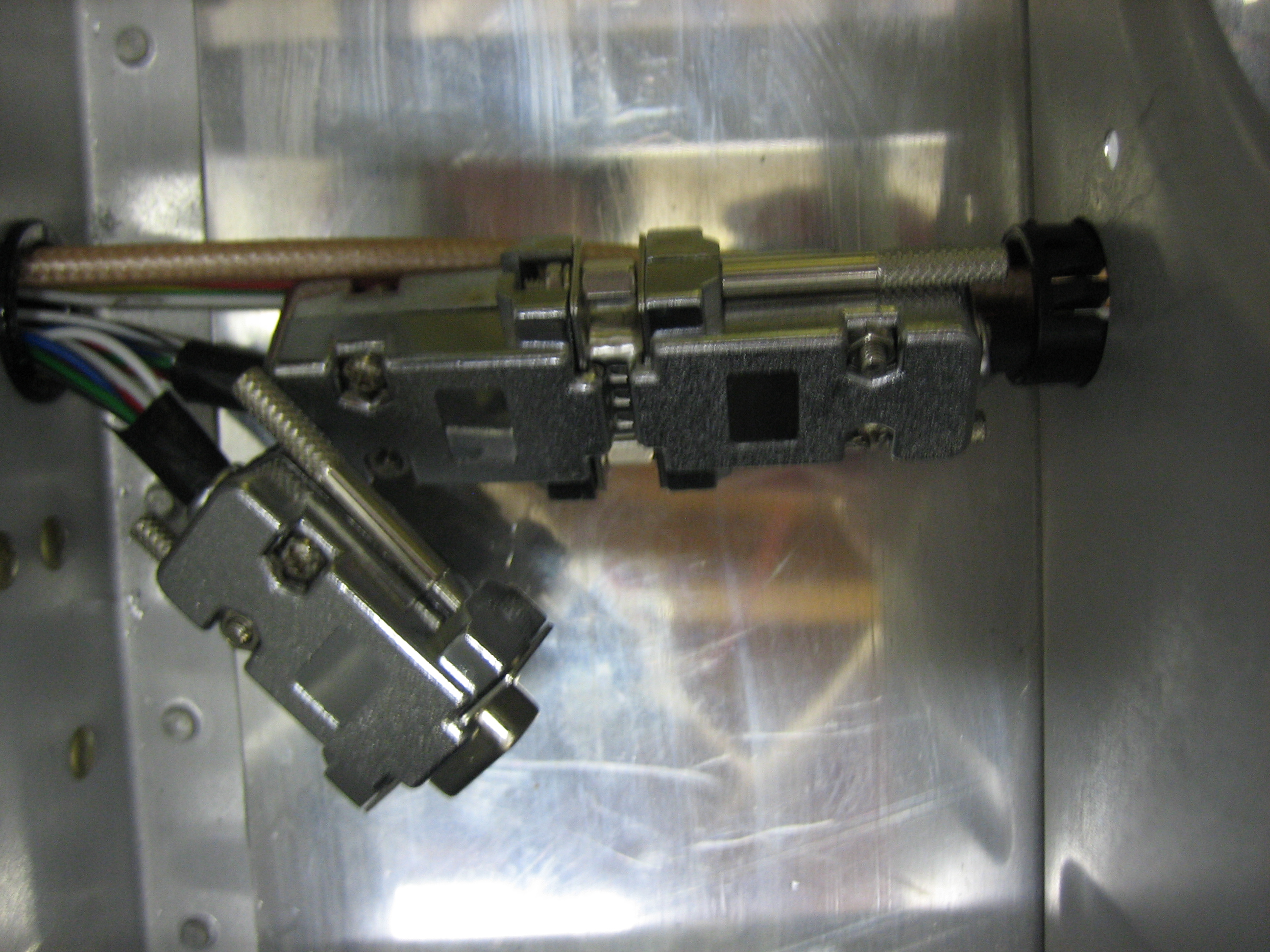
The next bay to the right of that contains the two output connectors for the splitter in the previous bay. I used one male and one female connector here since these aren’t electrically identical. The male connector is a standard SkyView network connector and it is connected to a cable that runs up behind the instrument panel. The other side of the splitter (the currently unconnected female DB-9 connector) only contains the two serial TX and RX lines as well as the servo power, ground, and CWS lines. Another connector will attach here and go out to the right wing to hook up to the roll servo.
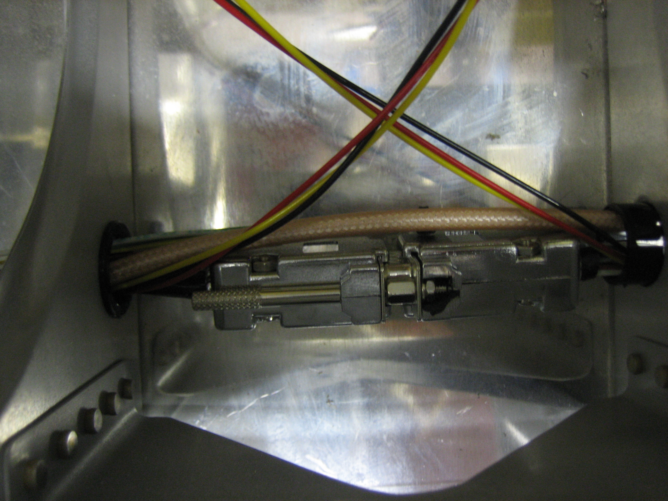
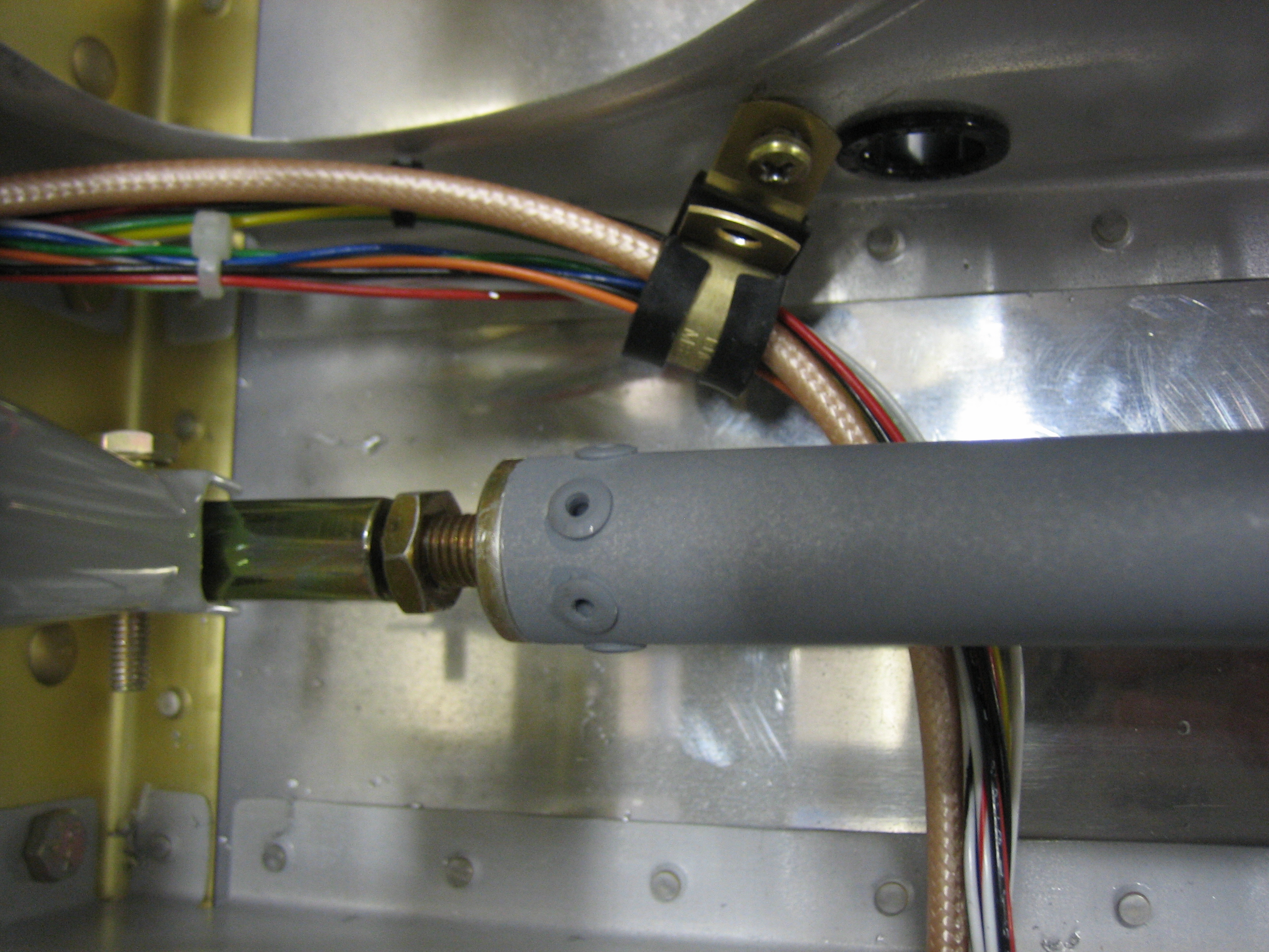
I also added another adel clamp to help stabilize the wires where they cross under the elevator push tube.
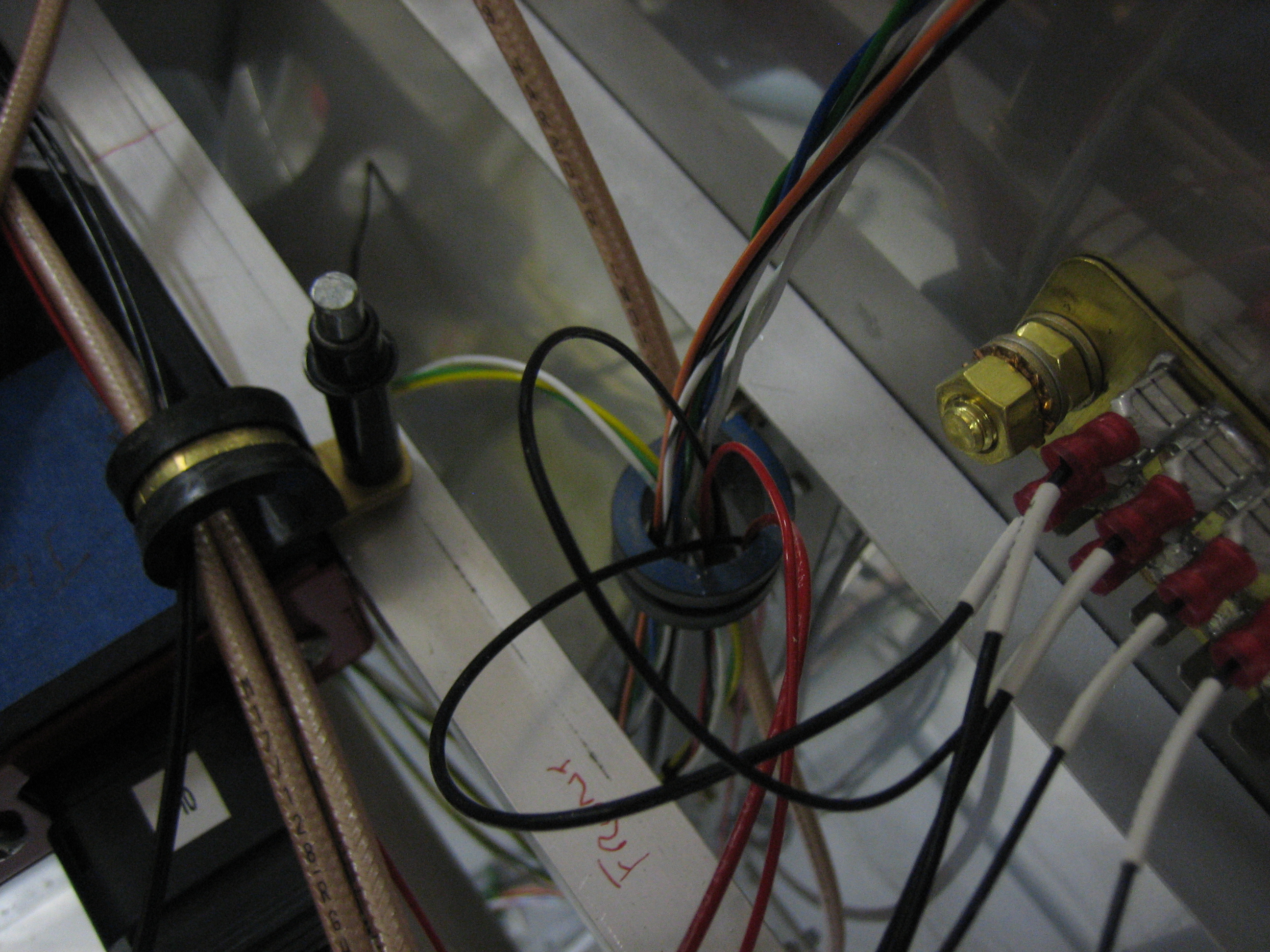
I hooked up the transponder power and ground wires. You can also see the yellow, green, and white serial lines as well as the SkyView network cable routed through here.