Wired Copilot’s Headset Jacks

I wired the copilot’s headset jacks tonight.  I wired the pilot’s side weeks ago, but for some reason didn’t get around to the copilot’s side until tonight.

On this side, I routed the wires over the duct like I meant to do on the pilot’s side.  I’ll secure these wires a little better later.

Installed GTN 635 Serial In Lines

I realized a couple of months ago that I needed one of the serial input lines on the GTN connected so that the SkyView could share traffic with it.  The avionics shop mailed me a few extra wires with high-density d-sub pins crimped on, but I’ve avoided installing them because it is such a pain to remove the connectors.  Anyway, I decided to bite the bullet and do that tonight.  It wasn’t too bad.  I had everything back together and the wire harness zip-tied in under an hour.  I went ahead and hooked up three serial in lines in case I ever need to hook anything else up.

Hooked up GTN Serial Input

No pictures tonight, but I hooked up one of the GTN serial inputs to one of the SkyView serial outputs so that the SkyView can share traffic information with the GTN.  I configured the SkyView to output TIS traffic, but it wasn’t clear how to configure the GTN to receive the traffic. I tried configuring it as a GTX with TIS, but then it wanted to put a transponder control box on the screen (though it had a red X through it).  I’ll need to ask on the Dynon forums to see if anyone has any ideas.

Installed Avionics Interconnect DB-25 Shells

I installed the last few wires in the avionics interconnect connectors and then installed the shells.  Afterward, I tidied up the wiring bundles a bit.  The loops of extra wires there are the other two (currently) unused GTN serial input lines and the dimming bus wires from the GTN and audio panel in case I choose to hook them up to the SkyView at some point.

Installed Aileron Pushrod Boots and Gemini Pitot Tubing

One of the biggest sources of air infiltration in the RV is the large hole in the side of the fuselage that allows the aileron pushrod to exit the fuselage.  When flying at high altitudes, ice cold air comes in through this hole and then comes up through the seat belt attach holes, stick boot hole, etc.  It also makes the seat pans really cold which can make sitting in the plane really uncomfortable.  The solution to this is to install boots around the pushrods to block the air.

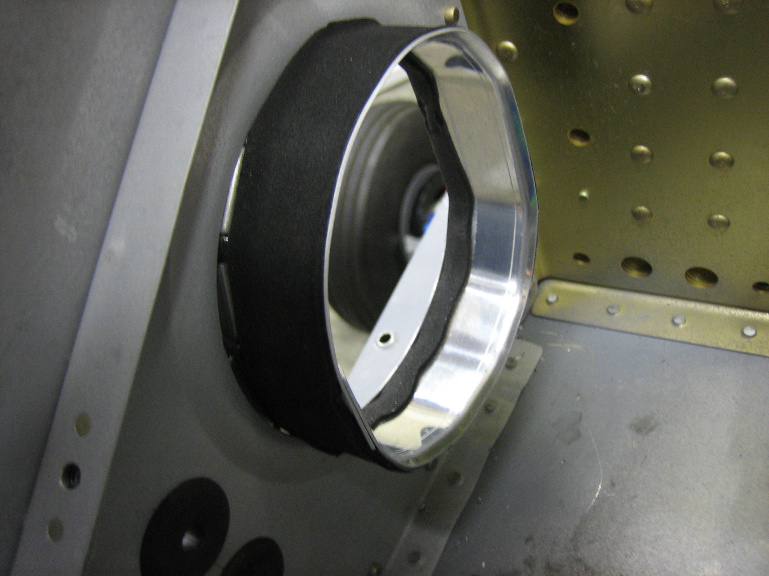
I installed the aileron pushrod boots from Classic Aero Design.  These are more expensive than others on the market, but after installing them, I think the extra cost is absolutely worth it.  These are very well designed and really easy to install.  First up is to install the mounting ring.  This is flexed into place so that the foam covered flange tucks between the outer fuselage skin and the adjacent rib.  The ring is then expanded outward until the predrilled holes align.  A couple of pop rivets anchors the rings in place.

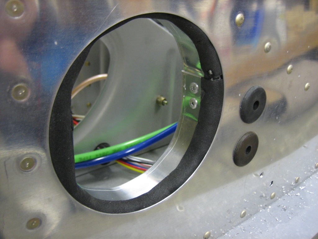
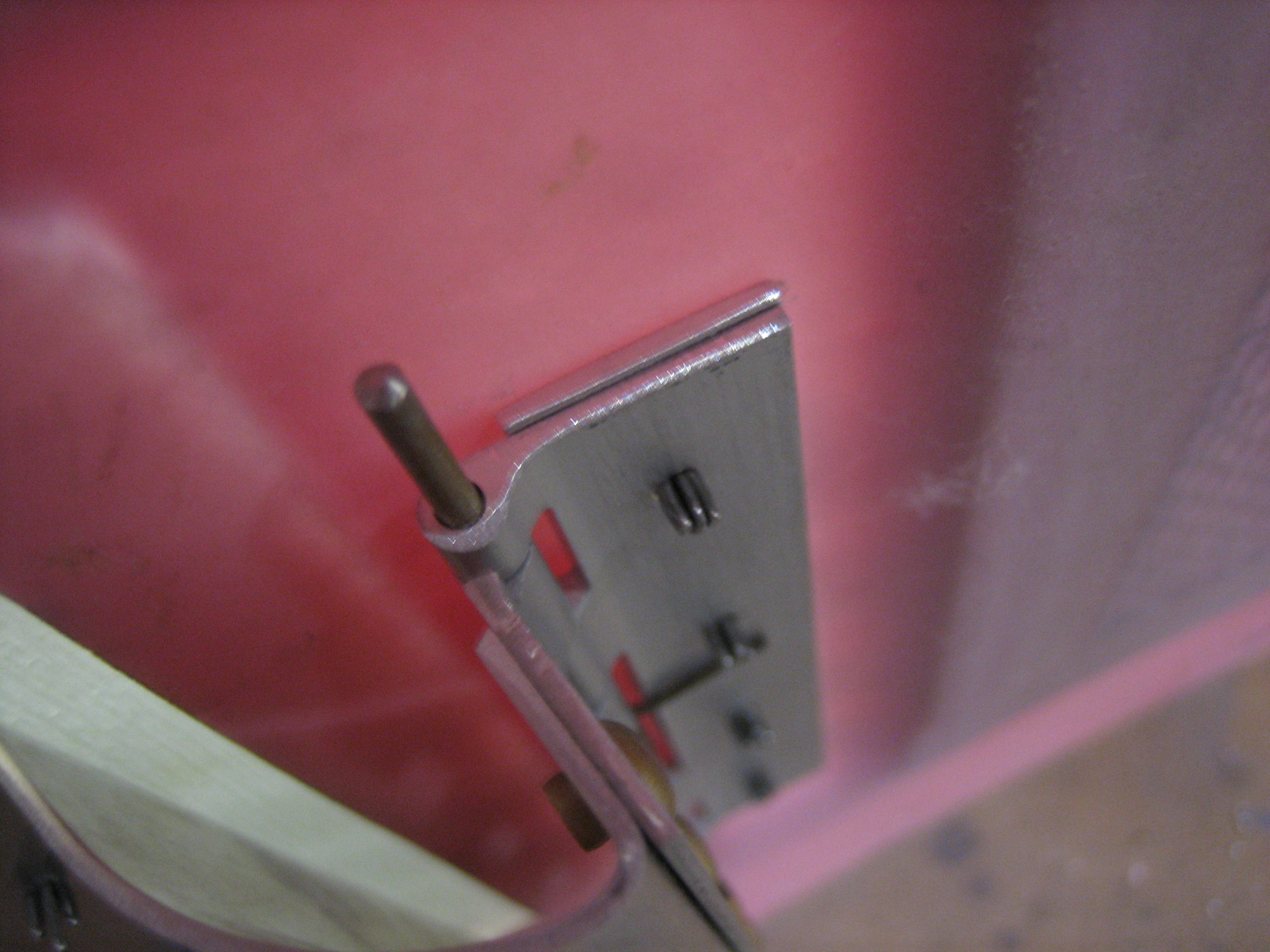
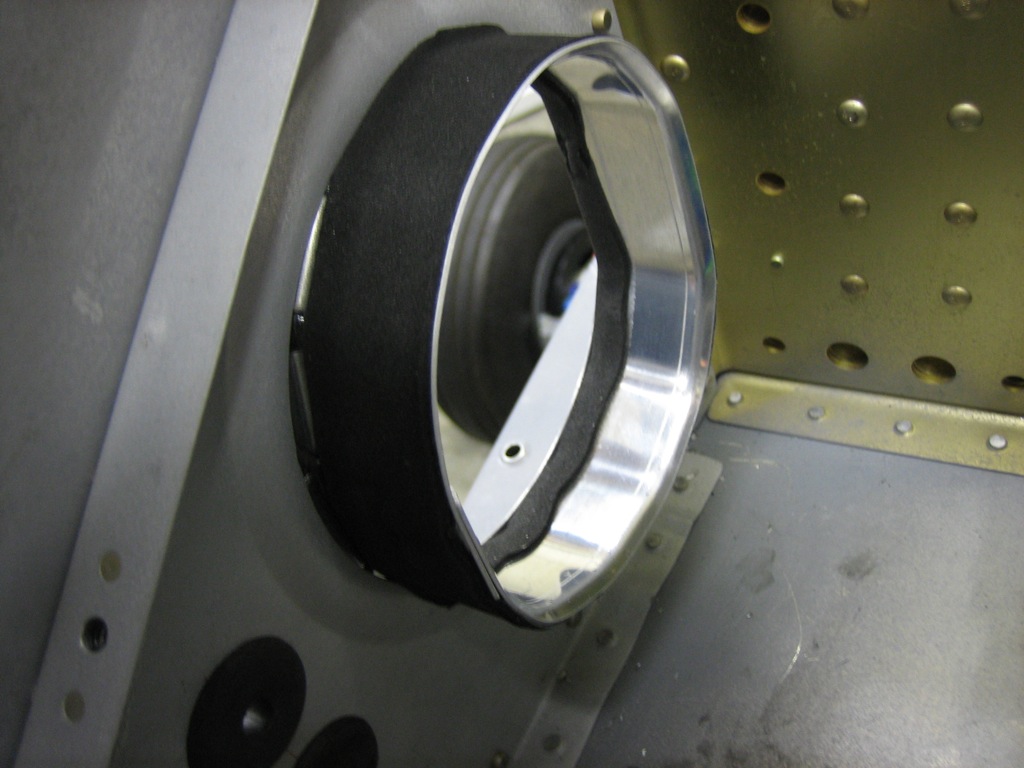
Next, a strip of adhesive backed foam is adhered to the outside of the flange.  Notice that the inboard edge of the flange is bent outward slightly.

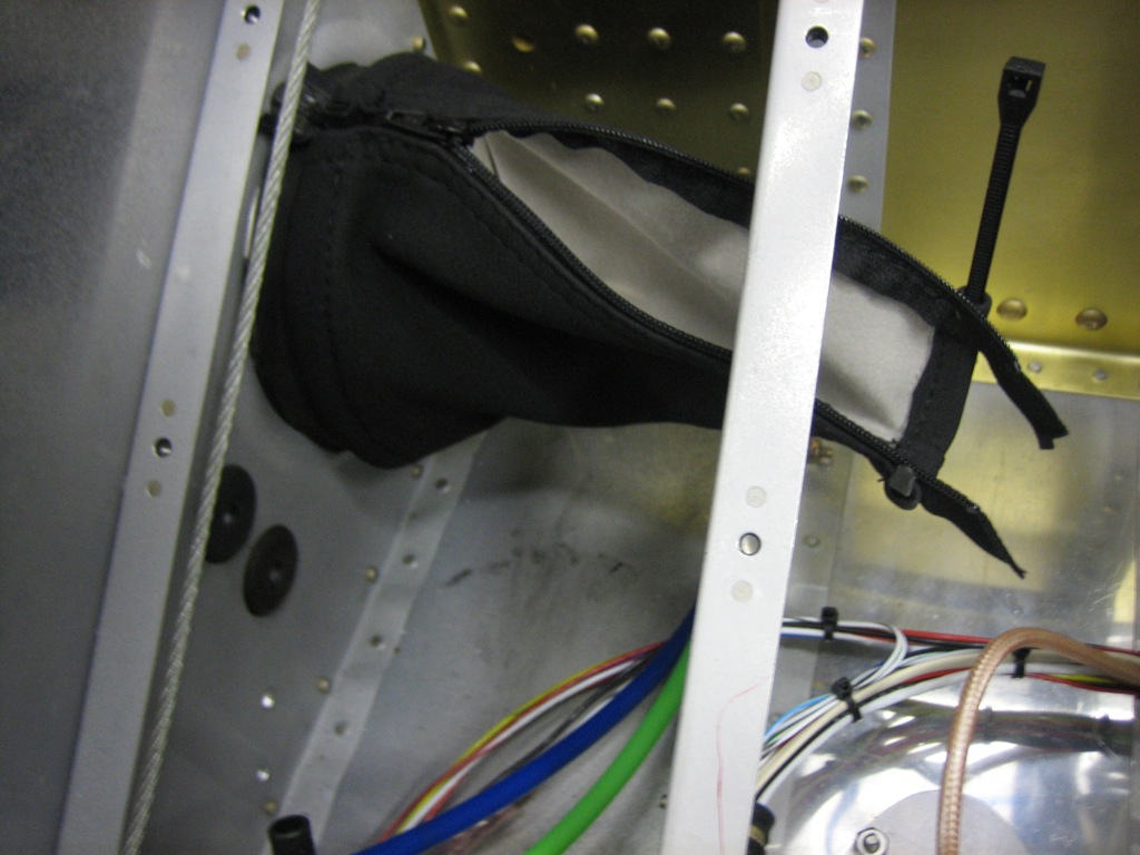
The boot is then installed over the flange and a zip-tie is used to cinch it down against the foam strip.  The bent edge of the flange keeps the end from popping off the flange.  Once the pushrod is installed for good, another foam strip will be adhered to the pushrod and the inner zip-tie will be used to anchor it.

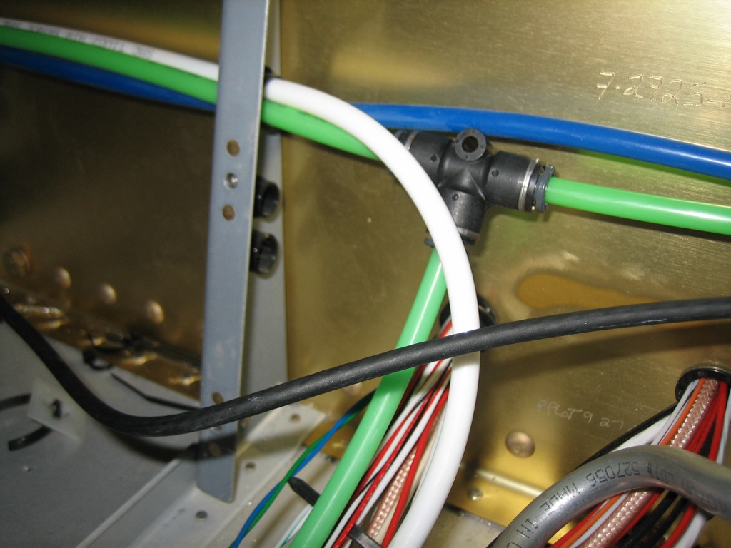
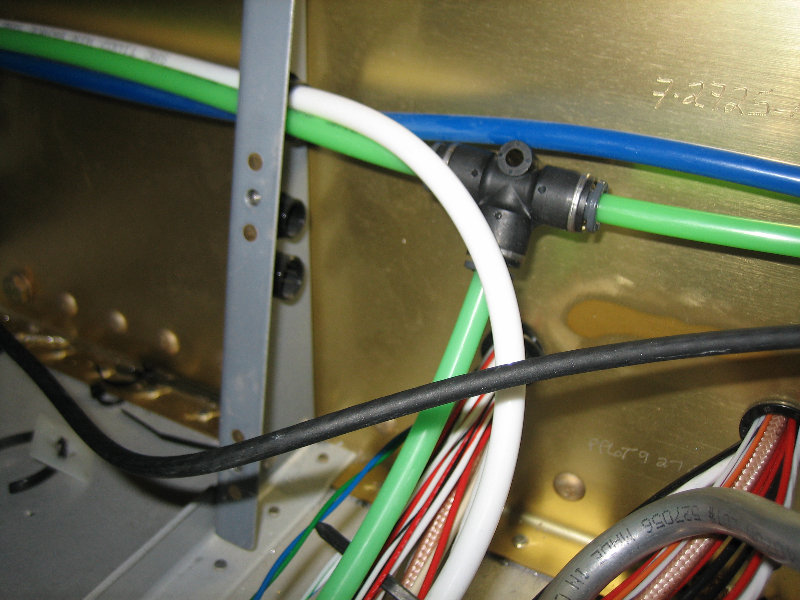
Finally, I tapped into the pitot tube to run a line up to the Gemini.  I spoke with TruTrak yesterday, and the Gemini PFD has been delayed a couple of months, so they’re going to send me the Gemini ADI which has the exact same mounting holes and wiring/plumbing connections.  Once the PFD is available, I’ll swap the ADI out for it.

Finished Interior Lighting

I decided to finish up the interior lights tonight.  The final light is a small stick-on LED light strip that will cast a dim glow in the footwell so that I can see where my feet are and see the fuel selector.  I’m going to install it to the bottom of the control cable support bracket, but I need to paint it first, so it’s just held on with a piece of masking tape right now.  I put a 39kΩ resistor inline with the lights to dim them down pretty far.  The light should be dim enough that it’s not a distraction when flying at night.

With all of the wiring done behind the panel, I started zip-tying the bundles.

I also installed a connector shell over the panel ground block wires.  I *think* all of the wiring behind the firewall is complete now except for the final hookups to the TruTrak Gemini and the elevator trim servo.

Finished Flap Position Sensor Installation

I wrapped up the flap position sensor installation tonight.  I installed the 4-40 threaded rod between the bracket I fabricated and the position sensor and adjusted the length so that it moves the position sensor arm through the full range of travel.  I then installed a couple of locking jam nuts to keep the rod from moving.

Next, I configured the flaps with a couple of intermediate stop points.  I’ll duplicate these settings in the VP-X so that it will automatically stop at these points when I tap the flaps switch.  I probably won’t enable that feature during initial flight testing though.  Here’s the indication when the flaps are all the way up.

…and here’s the indication when the flaps are all the way down.

Worked on Tail Light and Oil Door

I installed a connector on the tail light along with a piece of heat shrink over the wires.  Once the rudder is installed permanently, I’ll install this on the bottom fairing and hook it up.

I decided to make a little progress on the oil door tonight.  I fabricated a spacer out of 0.063″ aluminum to pull the oil door in tighter at the hinge line.

You can see at the hinge line that the door is in nice and tight.  Without that spacer, the flexibility of the door and the force of the hinge spring was causing the door to bow out just slightly here.

Wired Starter Sense and Alternator Shunt Sense

I fabricated several 26AWG fusible links for the sense wires connected to the starter contactor and alternator shunt.  Here’s the one for the starter contactor.

This attaches to the right post on the starter contactor so that the VP-X knows when the starter is engaged.  You can see the two additional fusible links below the starter contactor.  These connect to the shunt.

Here’s where these fusible links attach to the shunt.  Before connecting these wires to the shunt, I attached the battery charger to the alternator side of the shunt to determine the correct orientation.  Attaching the two sense wires to the wrong sides of the shunt would result in a negative current indication from the alternator.  If I didn’t determine the correct orientation now and got it backward, it would require reversing the sense wires at the EMS end which would be challenging once for the forward fuselage skin is riveted on.