Bonded Cowl Inlet Seals and Cowl/Plenum Filler

I haven’t worked on the plane in a bit because I’ve been laid up with the flu.  Now I’m fine but Jenn and the kids have it, so I headed out to the garage after everyone went to bed early.  I used some contact cement to bond the cowl inlet seals to the mounting strips.  I only took a picture of the lower left one, but all four are done.

Next, I mixed up some epoxy/micro and filled the weave and low spots on the plenum.

I had a little extra, so I put a little more on the upper cowl to fair out the area below the oil door in order to match the curvature.

Painted Underside of Plenum

Well, the battery was dead again today.  I’ve known what the problem is, but I haven’t decided what to do about it.  When I was first putting together the electrical system design, I decided that I wanted the interior lights to work even if the battery master was off to help with baggage loading, boarding, etc.  Later, when I settled on the dual color light and dimmer, the design required running power to the dimmer first, and then to the color selection switch and then the lights.  I didn’t realize until the entire system was wired up that the dimmer leaks about 43mA even with the lights off.  With a 17AH battery, that leakage current effectively drains the battery in about two weeks.  I kept putting it off hoping I could find a way to preserve the behavior, but fix the current leak.  I ended up deciding to just move the cabin lights to the interior light circuit on the VP-X.  After doing that, my leakage current is now well less than 1mA which is more than acceptable.

I also mixed up some epoxy primer and painted the underside of the plenum.

Removed Propeller

I had planned on removing the propeller for a while since it’s really in the way while wrapping up the plane.  Doing this solo is kind of a pain, but can be done.  With this out of the way, I can walk from one side of the plane to the other with the garage door down.  It’s also going to make applying the rest of the RTV around the forward end of the baffles substantially easier.

Finished Sealing Baffles

I finished applying RTV around all of the junctions between the baffles and engine.  Here’s the forward end just behind the propeller.

This was one of the wider gaps between the baffles and engine.  I partially filled it yesterday to provide some support to allow the RTV to fill the gap.

Getting around the edges of the inter-cylinder baffles was a real pain.  I had to apply the RTV with a long aluminum rod.  I could reach this part by reaching down through the cylinders from the top, but the rest required reaching from the bottom around the intake and exhaust pipes, oil return lines, wires, cables, etc.  This isn’t the prettiest application, but it should be air tight.

The propeller control line wasn’t quite sealed by the grommet, so I had to apply a small dab of RTV to fill the gap.  I really hope I don’t have to take off these baffles for a really long time.

Painted Inside of Plenum, Installed Sniffle Valve Drain Line

I painted the underside of the plenum with some two-part epoxy paint which matches the baffles.  I wish I had ordered this paint prior to painting the baffles since it’s much more solvent resistant than the rattle can paint I used on them.

Between coats, I knocked out a couple of other small tasks.  First up was to wrap the engine mount tube with some silicone wrap where the fuel overflow tube is tie-wrapped.  I’ve read cautions about tie-wraps sawing through engine mount tubes due to vibration and trapped abrasive particles.  I’m not sure how likely that is here, but better safe than sorry.

I also fabricated the sniffle valve drain line and anchored it to the sniffle valve with a short piece of MIL6000 hose.  The line parallels the exhaust pipes, but jugs slightly left to clear the oil drain fitting.  The aft end is flush with the end of the exhaust pipes and includes a 15º turn down to match them.

I fabricated a short stand-off to space the line away from the exhaust brace.  This was primarily done to make the line parallel with the exhaust pipes.

Painted Top of Plenum

I painted the top of the plenum with several coats of the two-part epoxy paint and set it aside to cure.

Unfortunately, a bug landed in the paint before it was dry and became trapped.  I’ll have to sand this out and probably shoot another coat to fix it.

Installed Cowl Nutplates and Started Shaping Inlets

I added a couple of #8 nutplates to the inside faces of the cowl inlets.  The needed to be set forward of the aft edge about 1/2″ to clear the inlet seals.  You can also see that I used some epoxy/flox to fill the hole that I’ve been using to align the cowl up to now.  The plans specify three nutplates here, but the plans also don’t specify a plenum which results in substantially more force trying to separate the cowl halves.  With the plenum, there’s far less force trying to lift the upper cowl, so two nutplates should be just fine.

The upper and lower halves of the cowls don’t perfectly align at the outer edges of the inlets, so I mixed up some epoxy/micro and applied a fairly thick coat.  Most of this will get sanded off, but I’m pretty sure I’ll still have to add another coat.

Here’s the right inlet.  I managed to scrape away more on this side before the epoxy started to set up, but there will still be lots of sanding.

Laid Up Flange on Outer Inlets

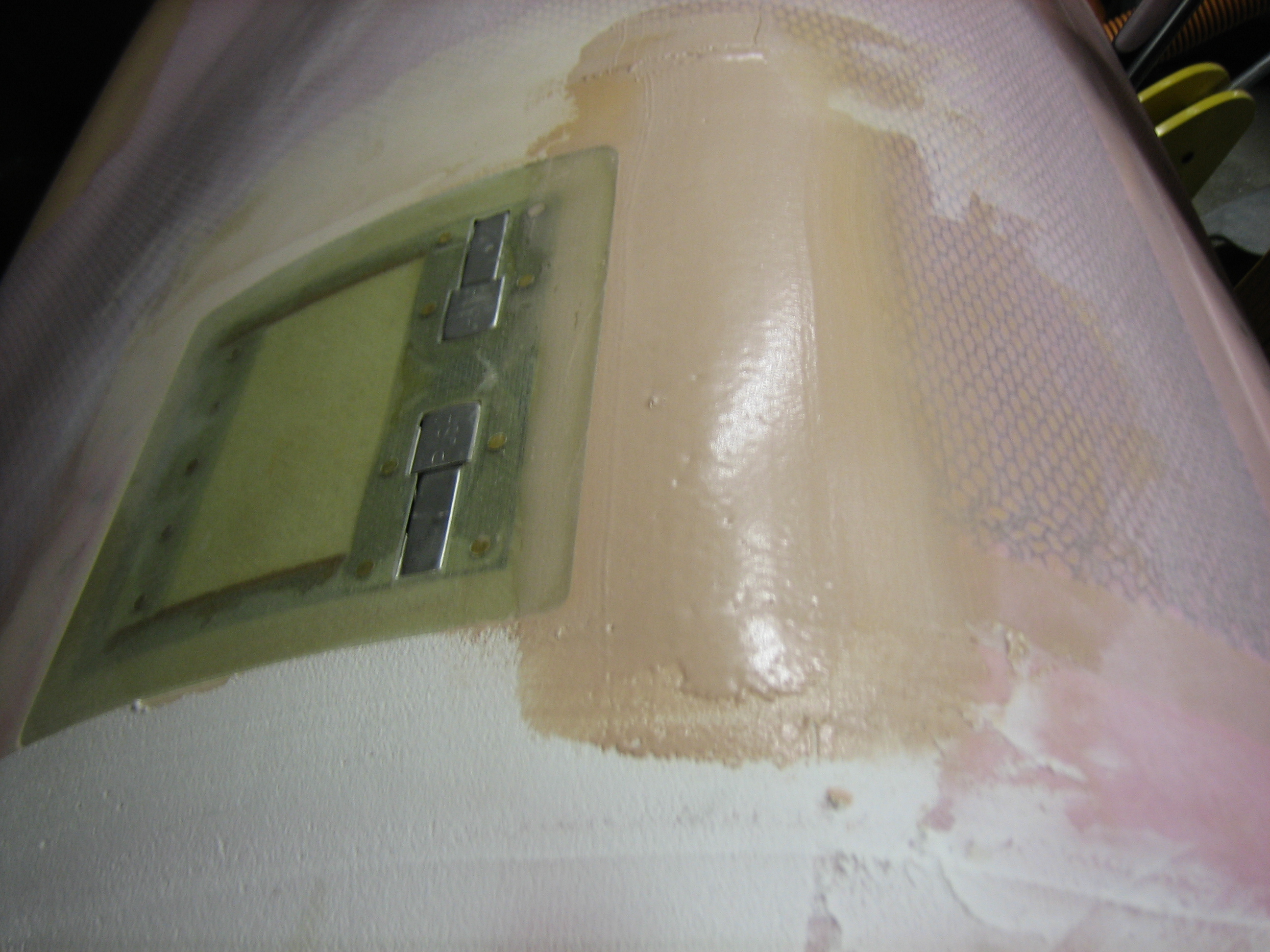
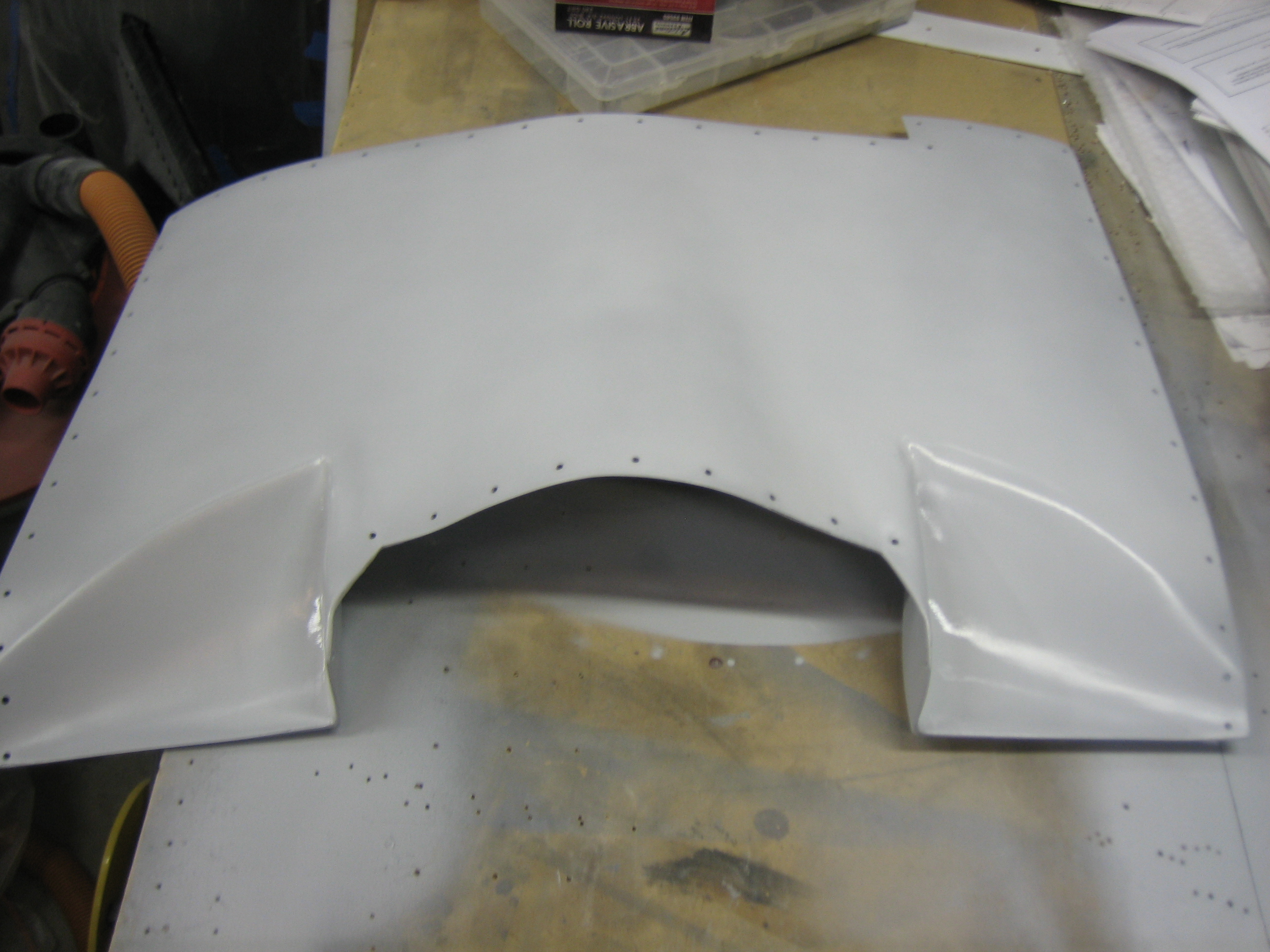
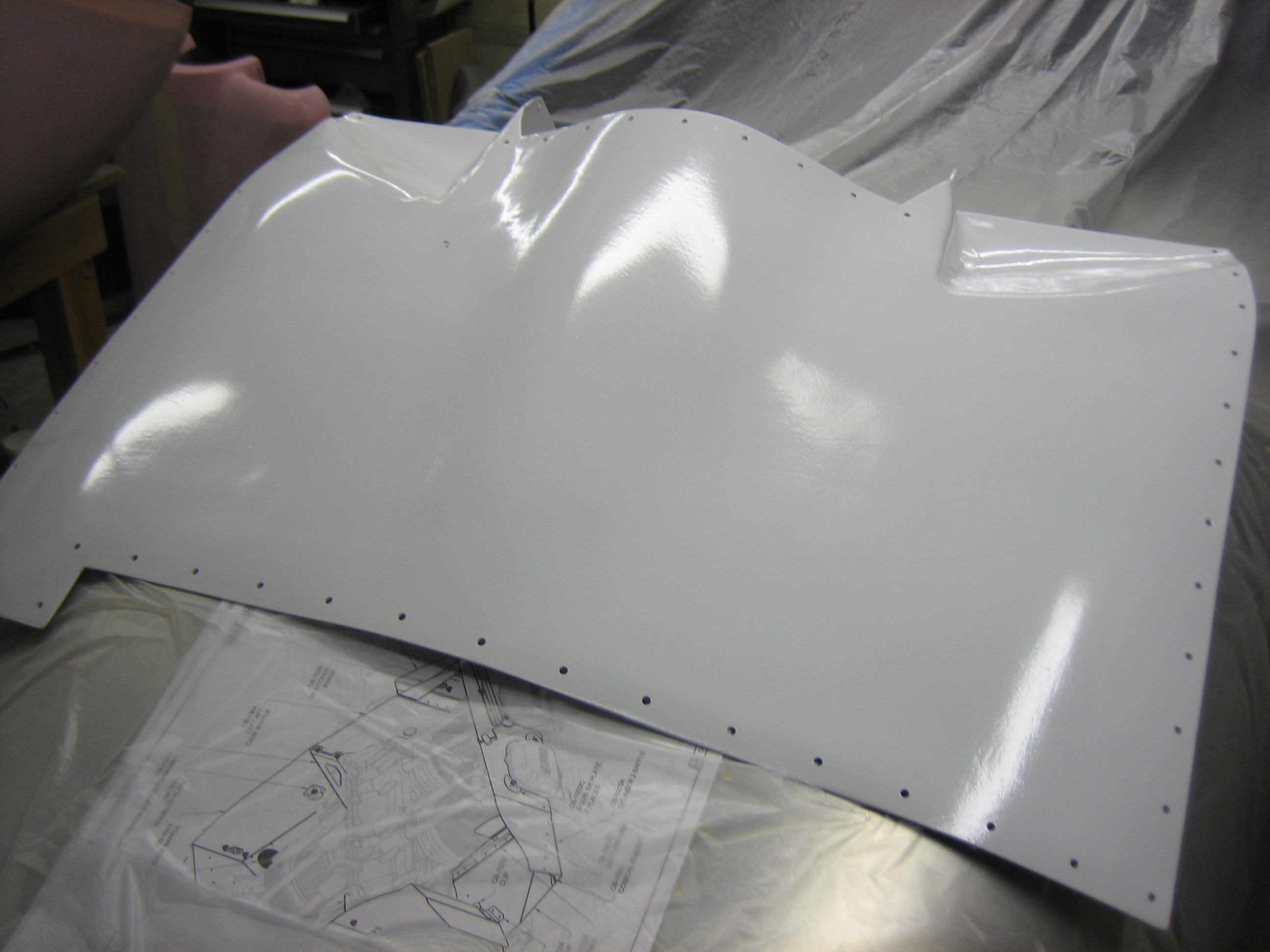
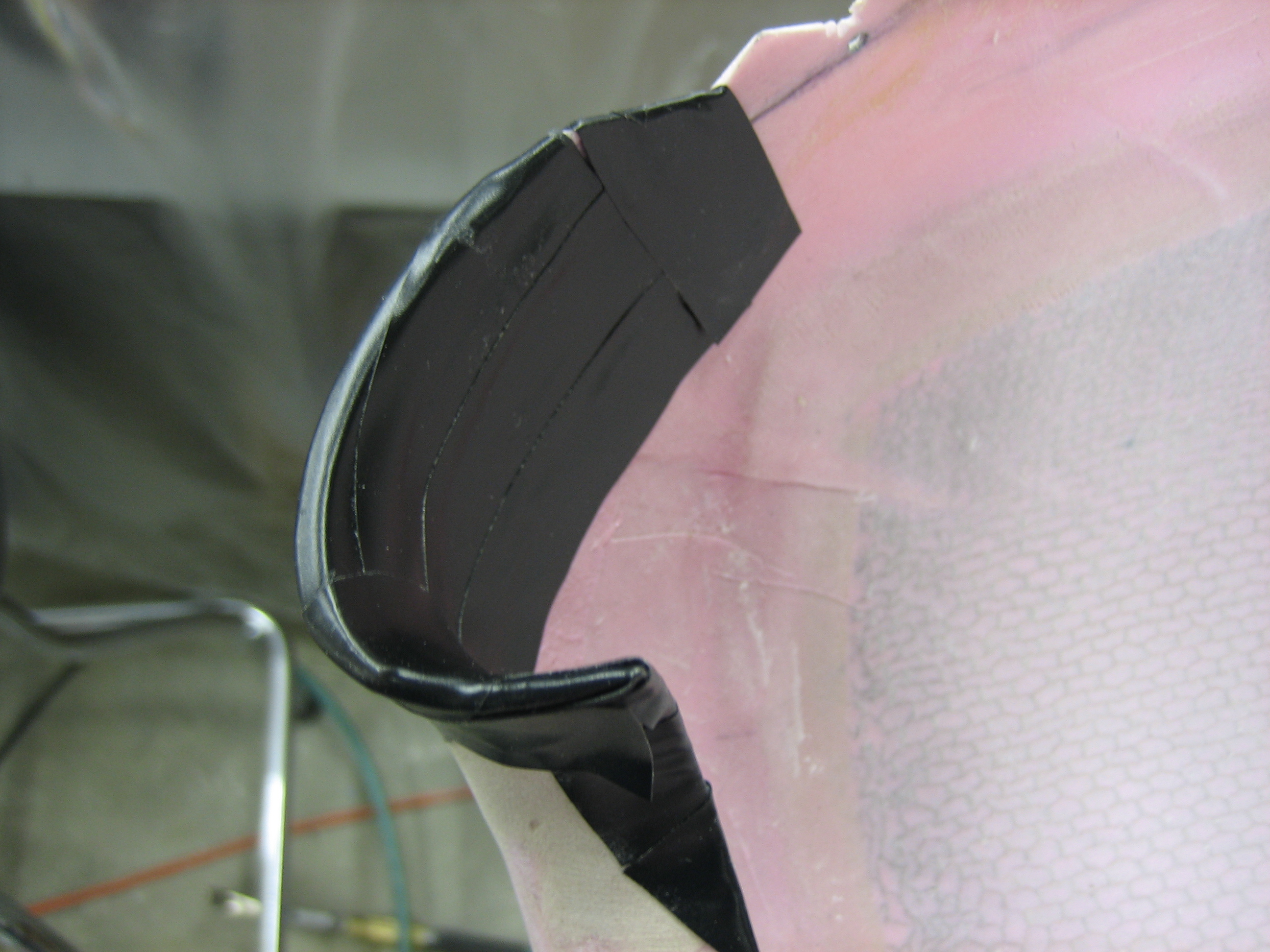
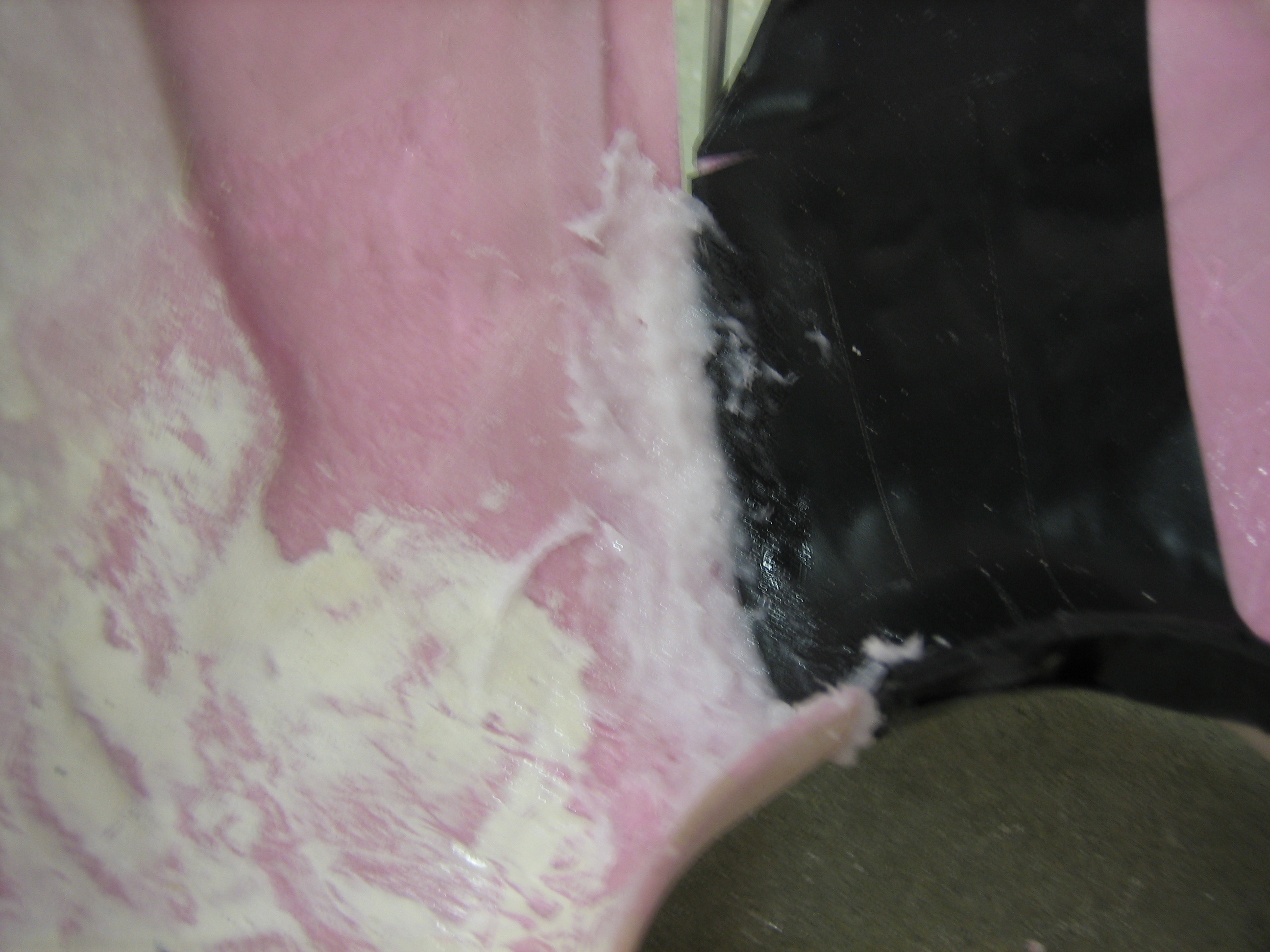
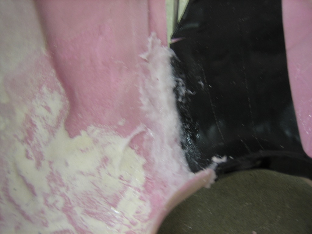
Where the upper and lower cowl halves meet on the outer ends of the inlets, the top and bottom sections simply butt together.  There is nothing tying the two parts of the cowl together at this point which allows some relative movement, and air entering through the gap is just added drag since it doesn’t help with engine cooling as it’s dumped directly into the low-pressure area outside the baffles.  To address this, I’m adding some flanges to the lower cowl that the upper cowl will nestle over.  This will reinforce this area a bit and seal the gap.  To prevent the epoxy from sticking to the upper cowl, I covered this area with electrical tape.  I would normally use packing tape, but it can’t conform to the curves like electrical tape can.

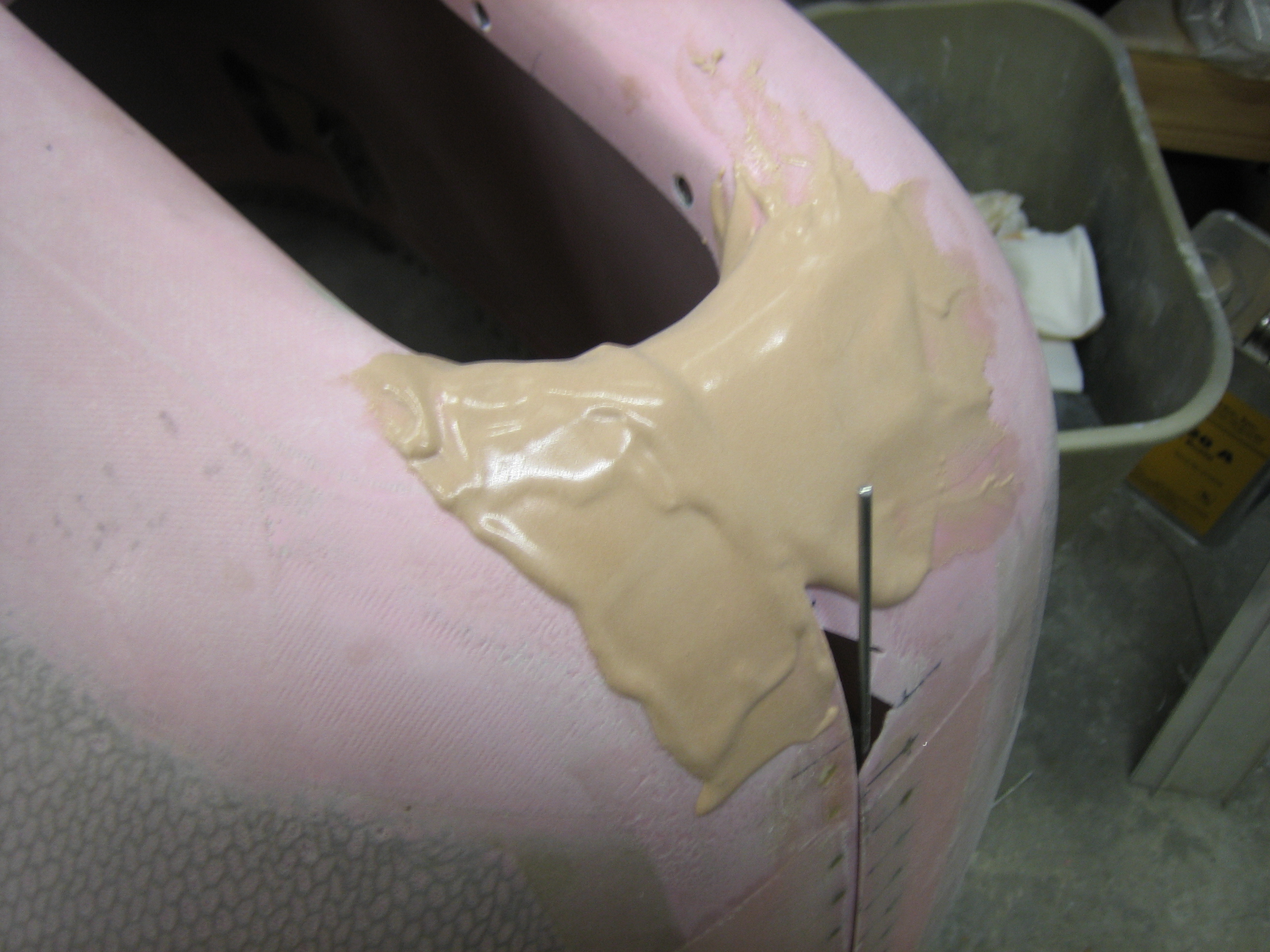
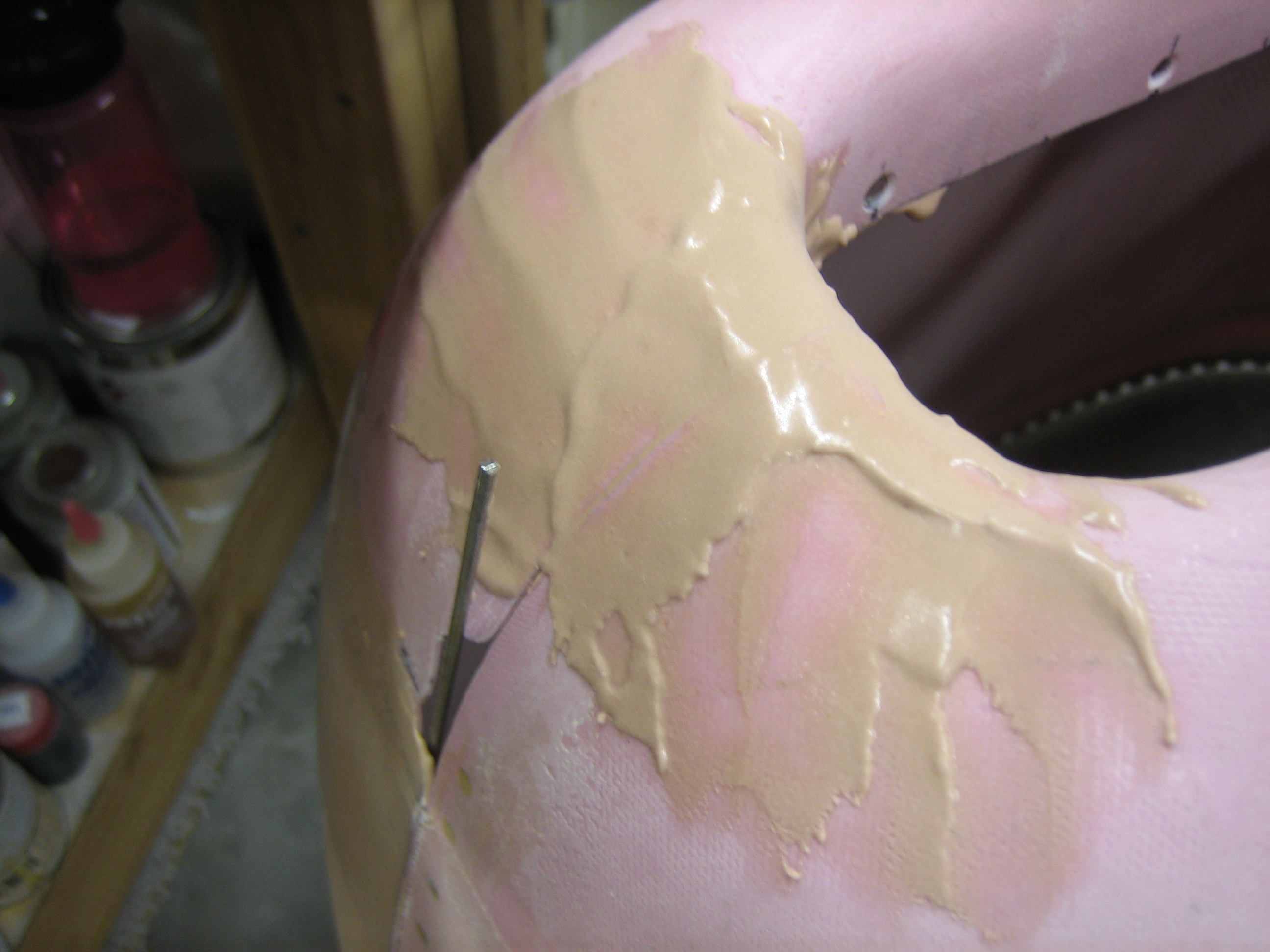
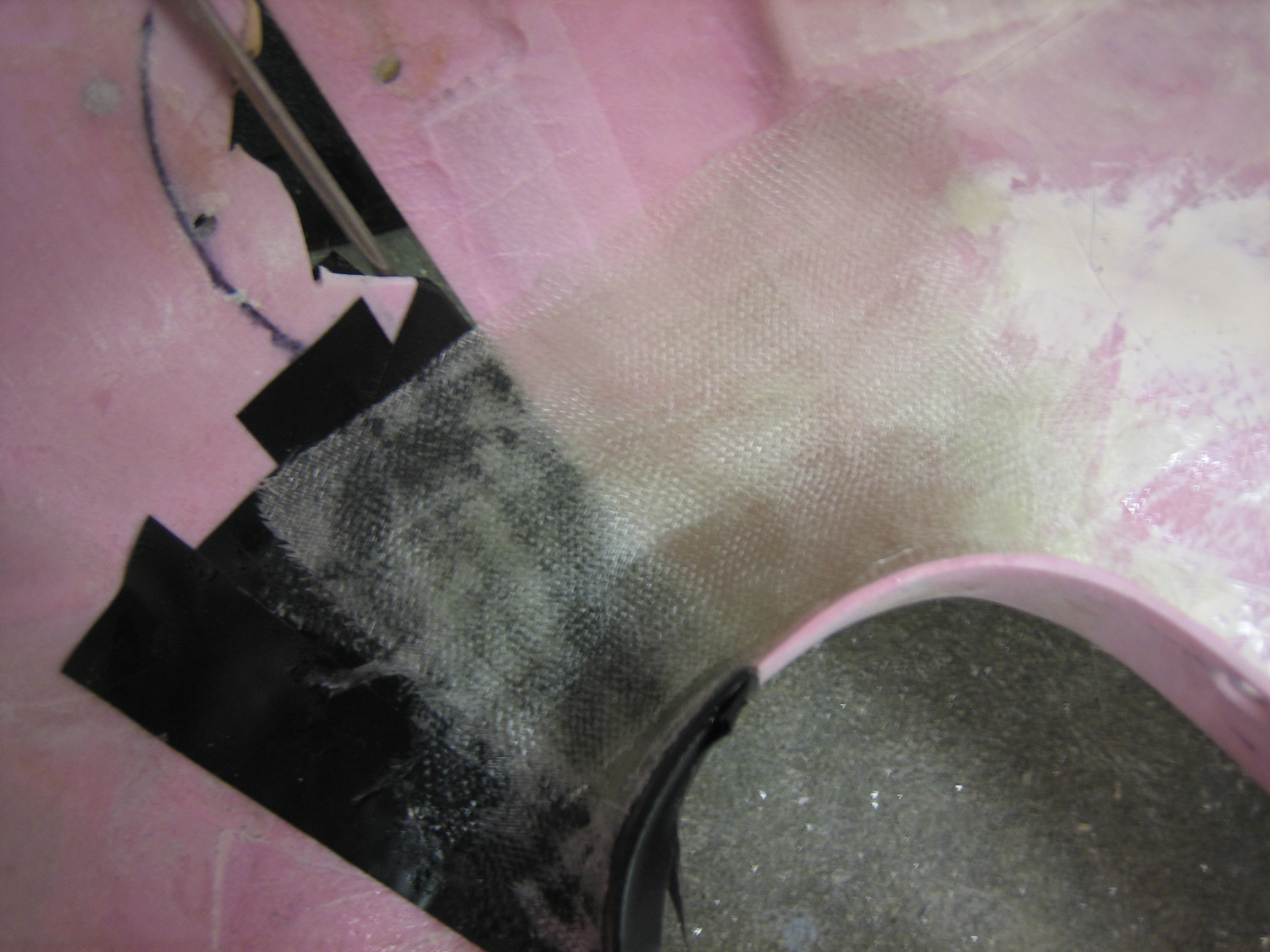
The lower cowl protruded beyond the upper cowl a small amount, so the glass wouldn’t have laid flat across the transition.  To fill in that step, I mixed up some epoxy/flox and made a small fillet.

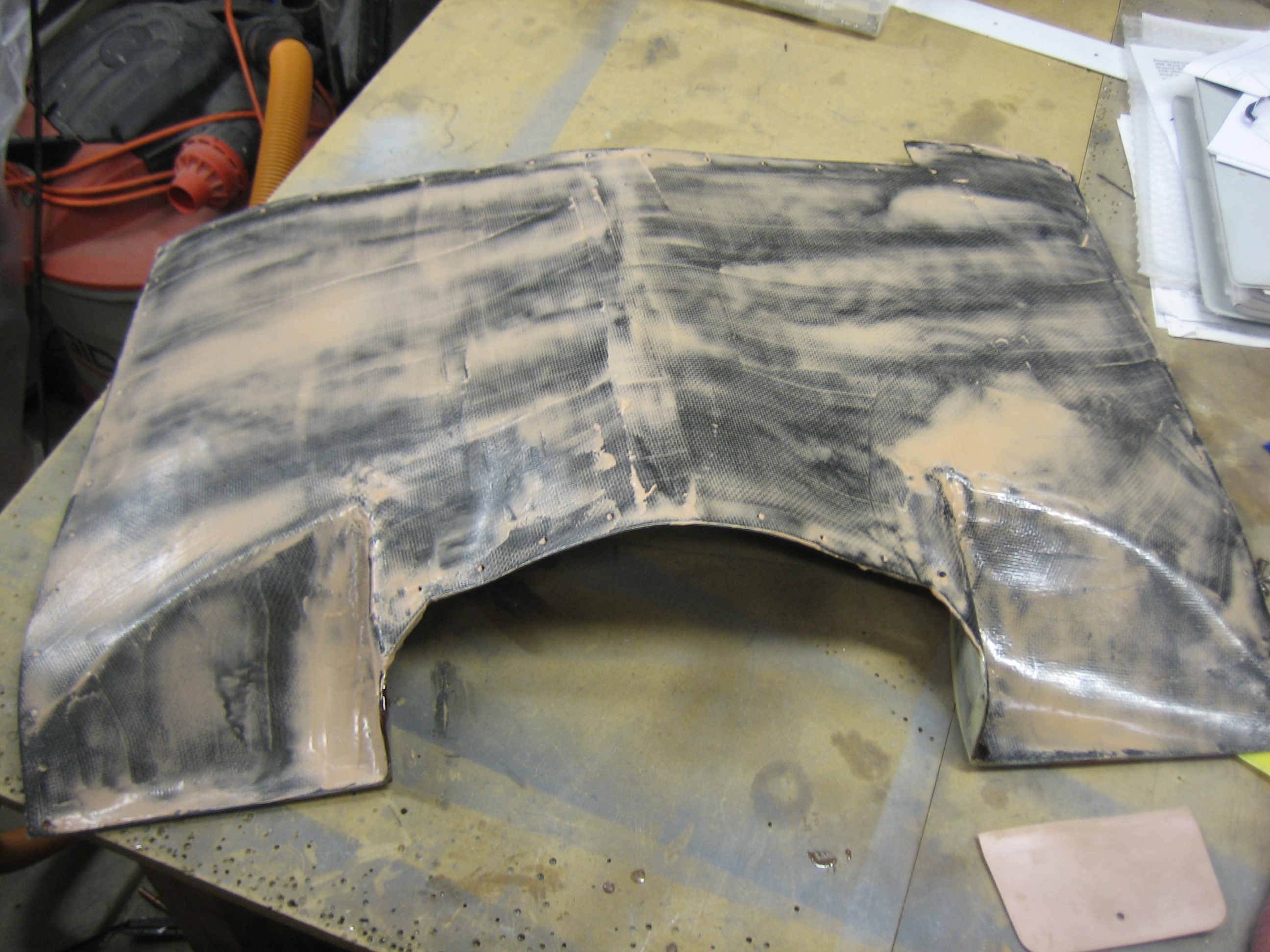
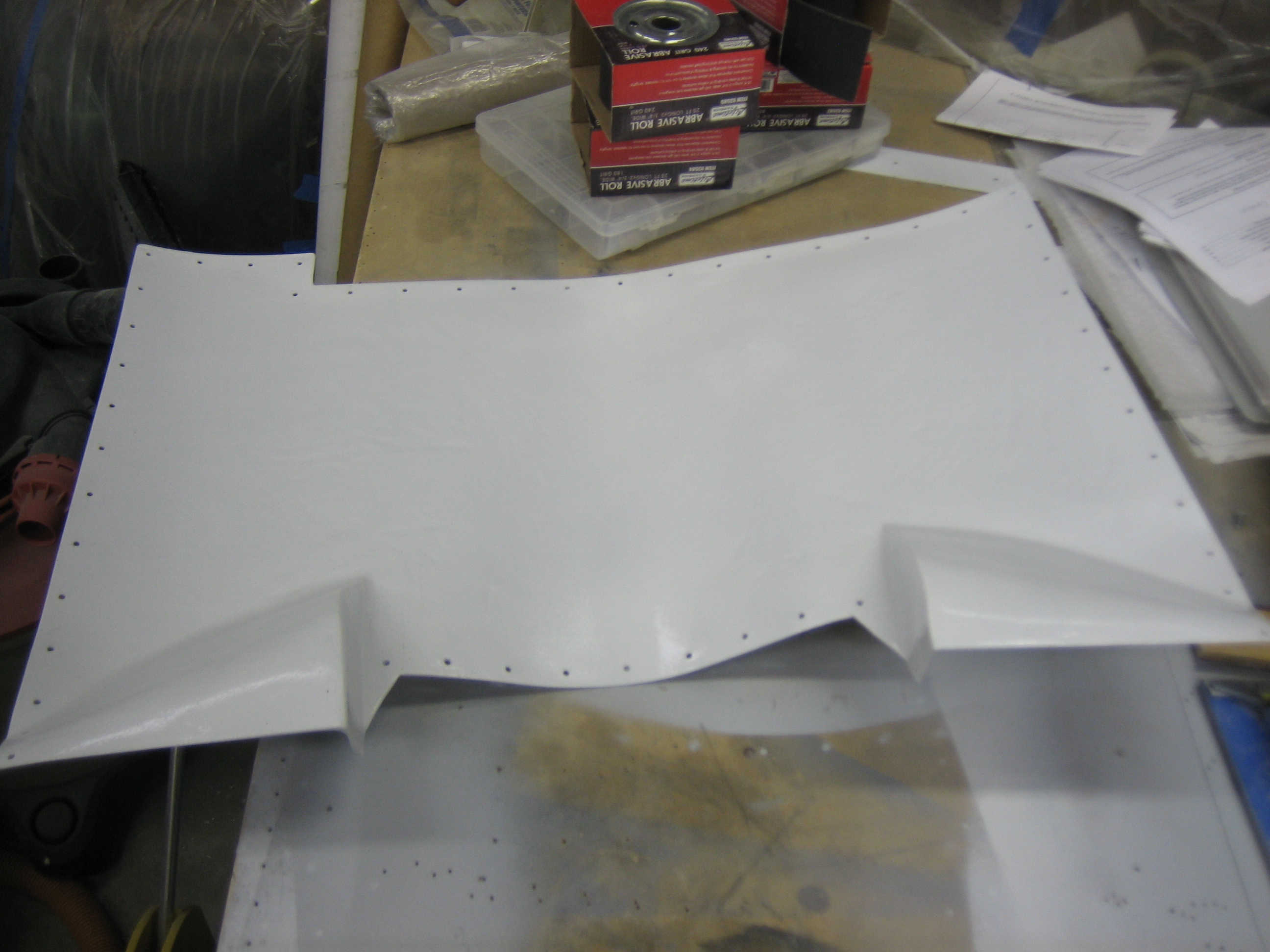
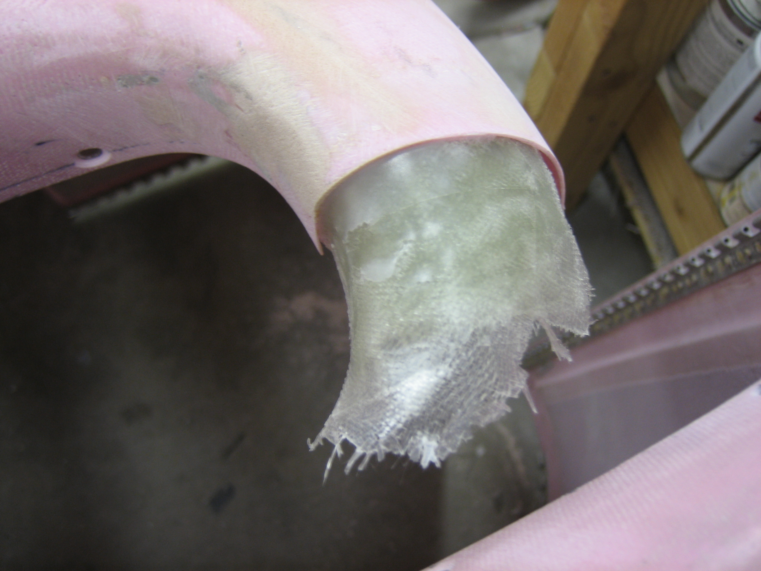
I then laid up about 6 layers of glass across the joint.  I’ll trim this back quite a bit after it cures.  It really only needs to stick up into the upper cowl 1/2″ or so.

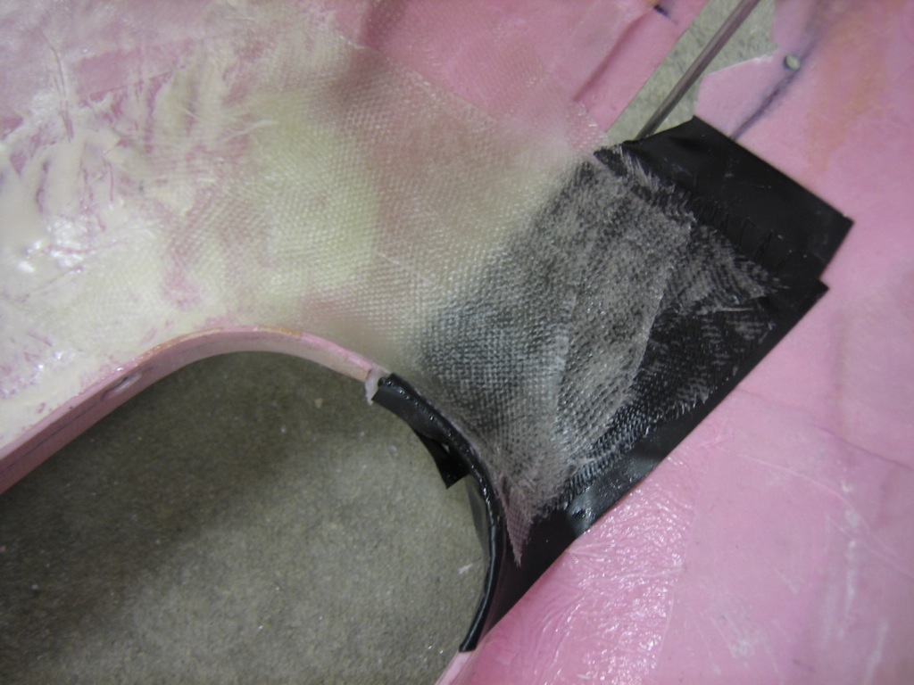
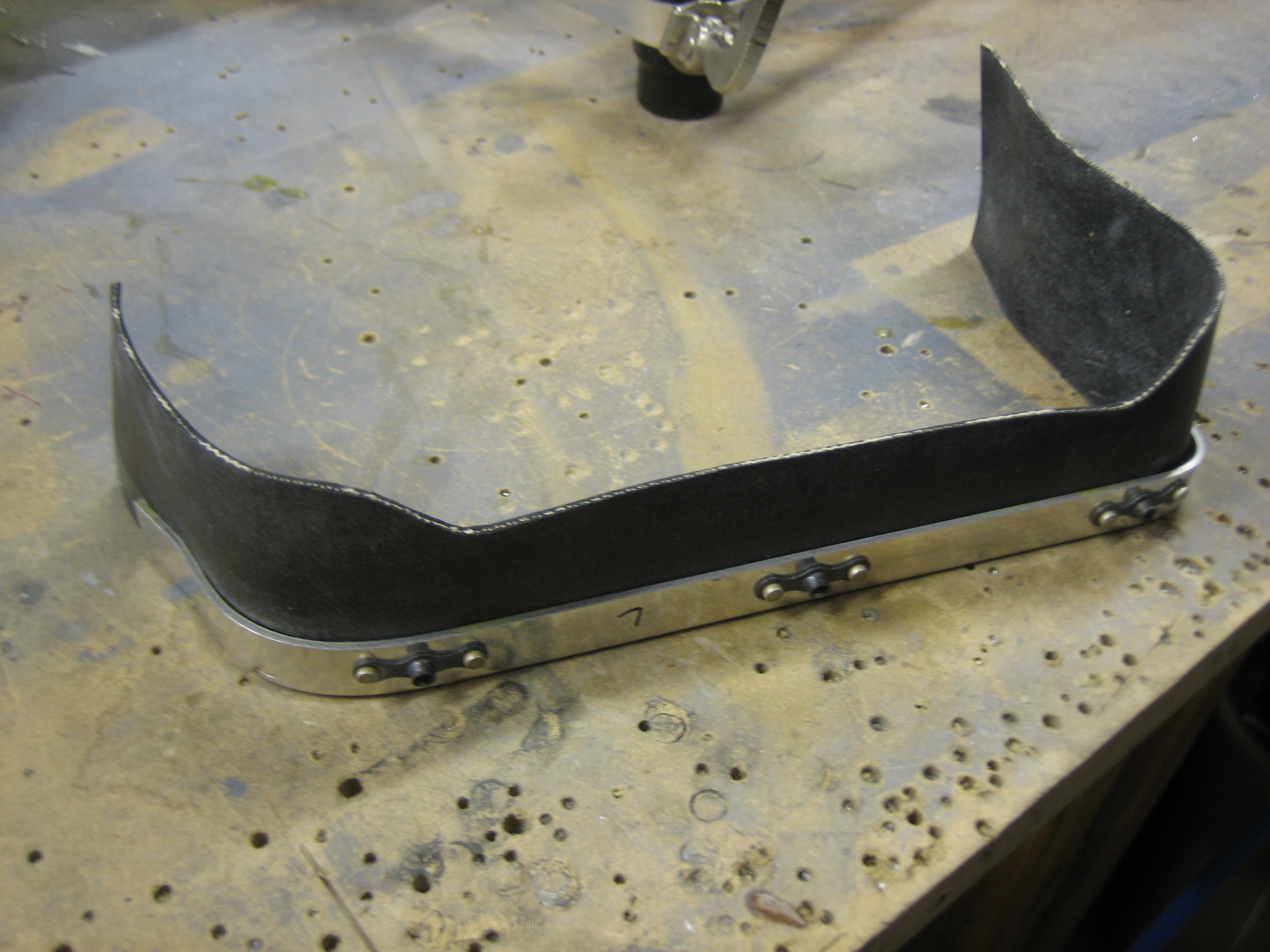
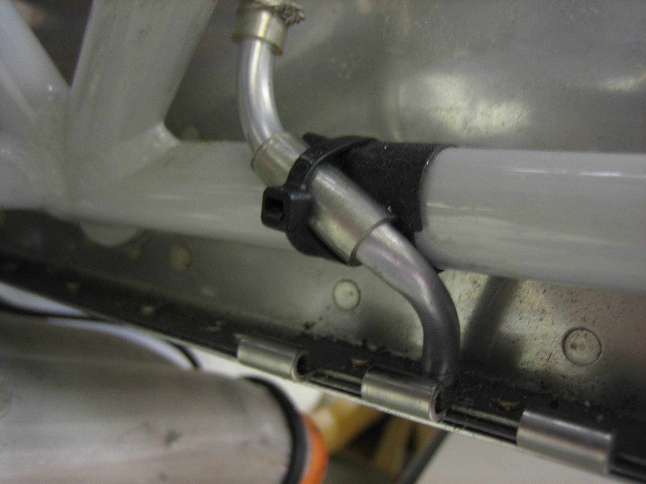
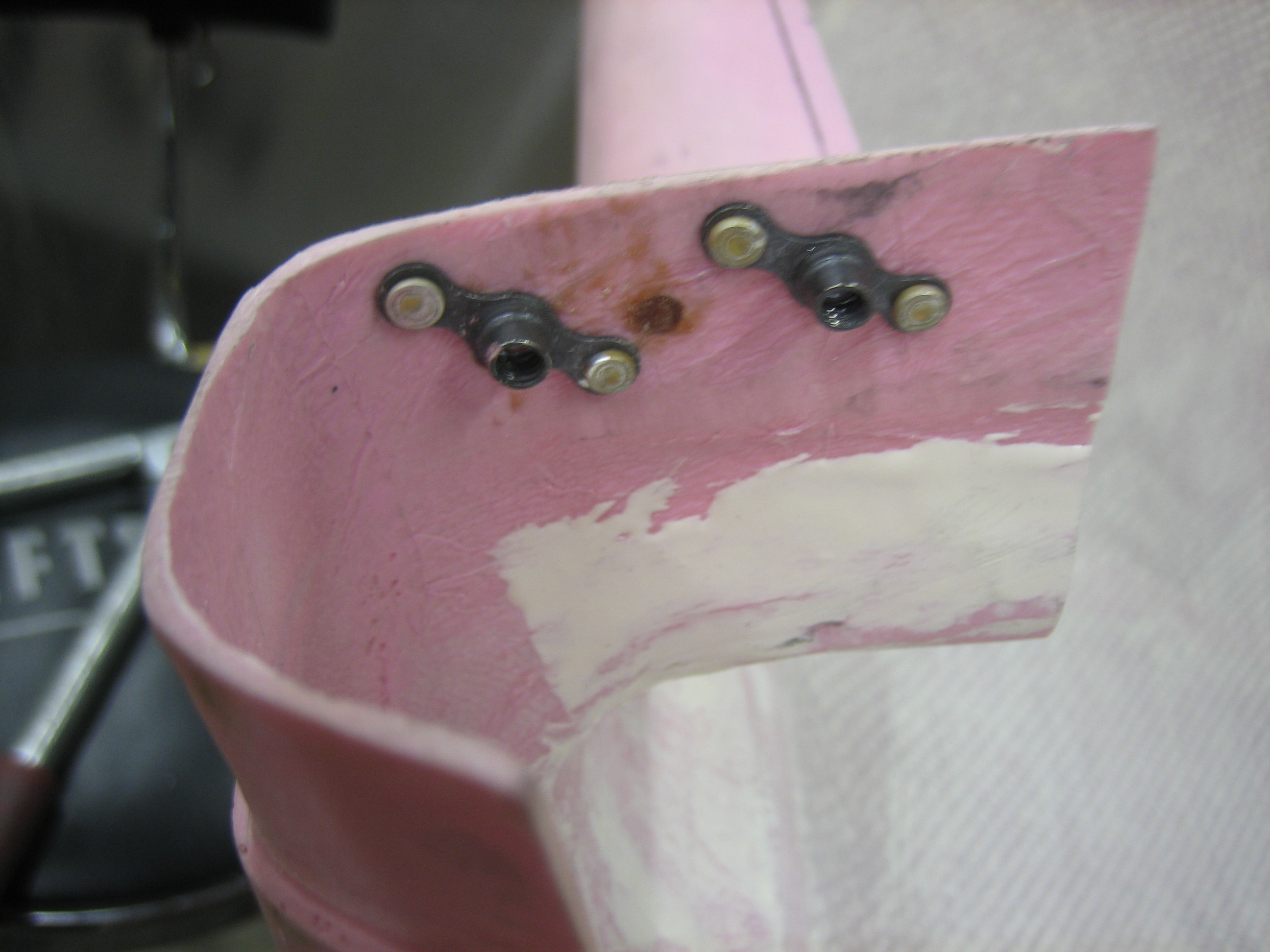
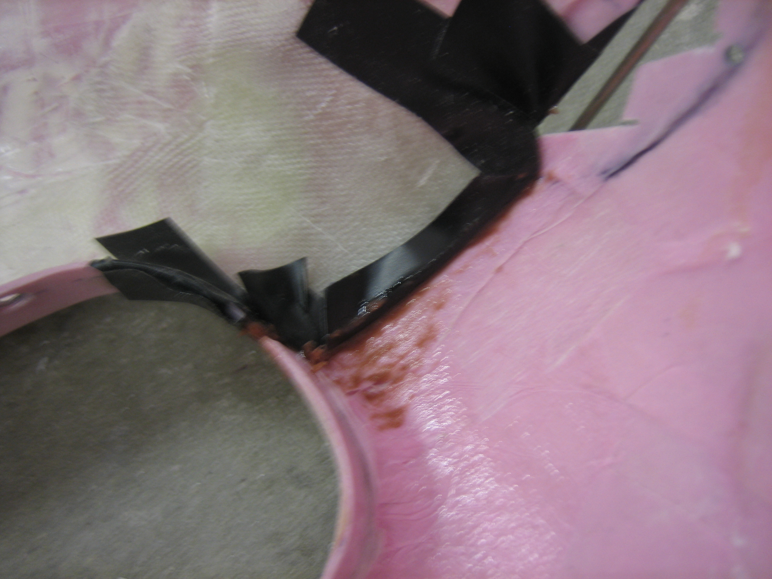
Here’s the other side.  You can see better here that the glass overlays the oval where the hinge pin covers will mount, so I’ll end up cutting back part of the flange to make room for the cover.

More Work on Cowl Flanges

I popped the two cowl halves apart and was left with a pretty nice flange.  I trimmed this down to about 1/4″ above the lip of the cowl.

I then taped it up, mixed up some epoxy/flox and reassembled the cowl.  This will provide a structural extension to the flange of the upper cowl (were there was a tiny gap between the top and bottom halves) as well as provide a perfect fit between the flange and the inside of the upper cowl.