Misc Firewall Forward Work

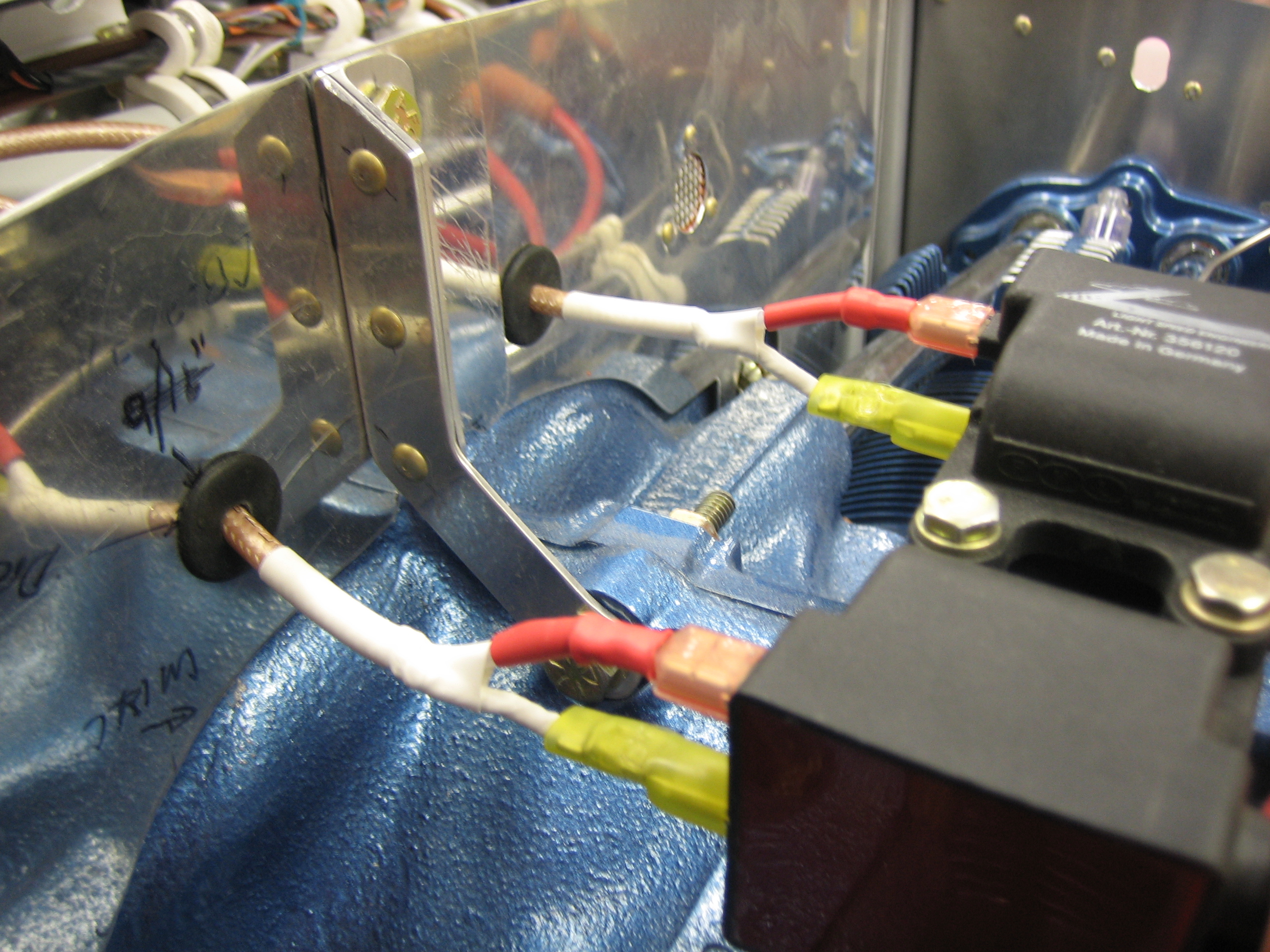
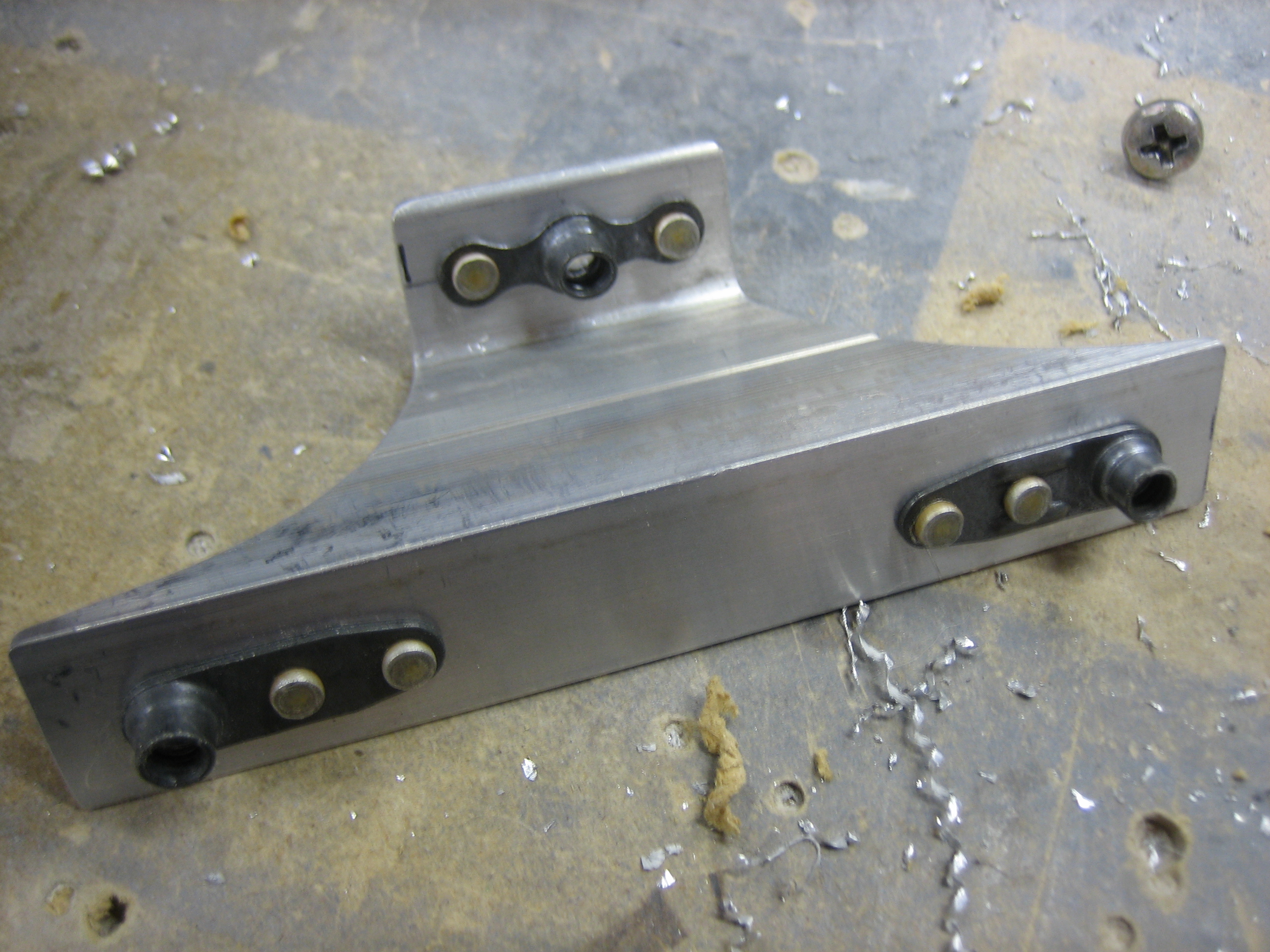
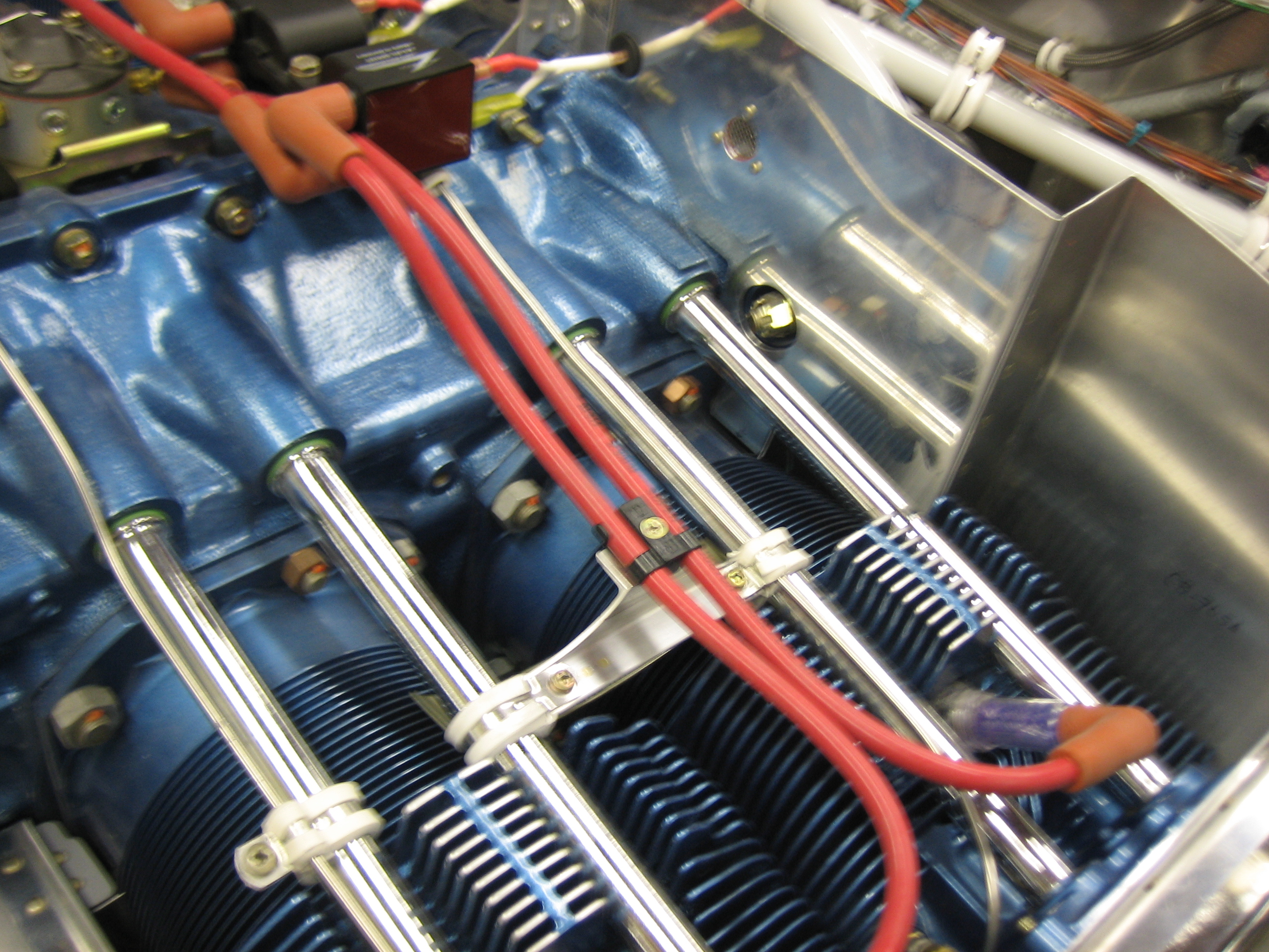
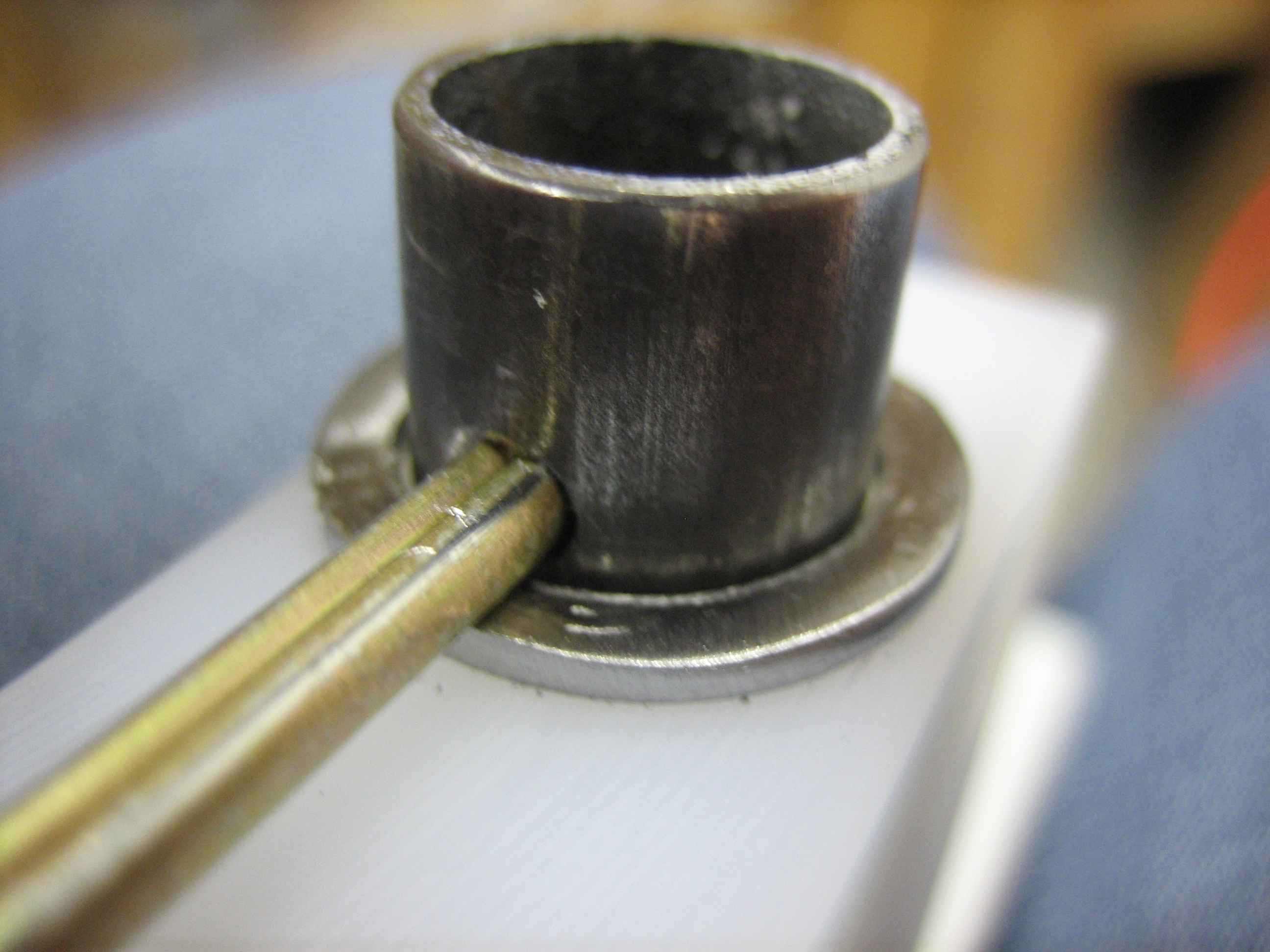
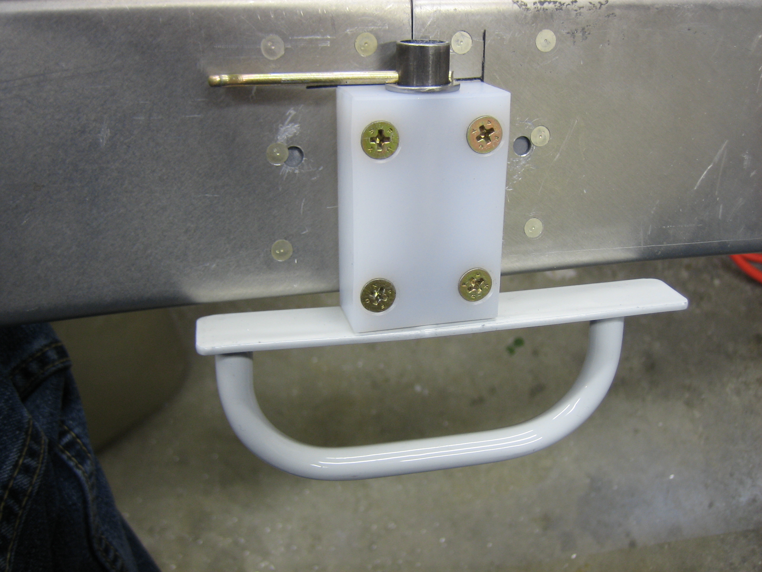
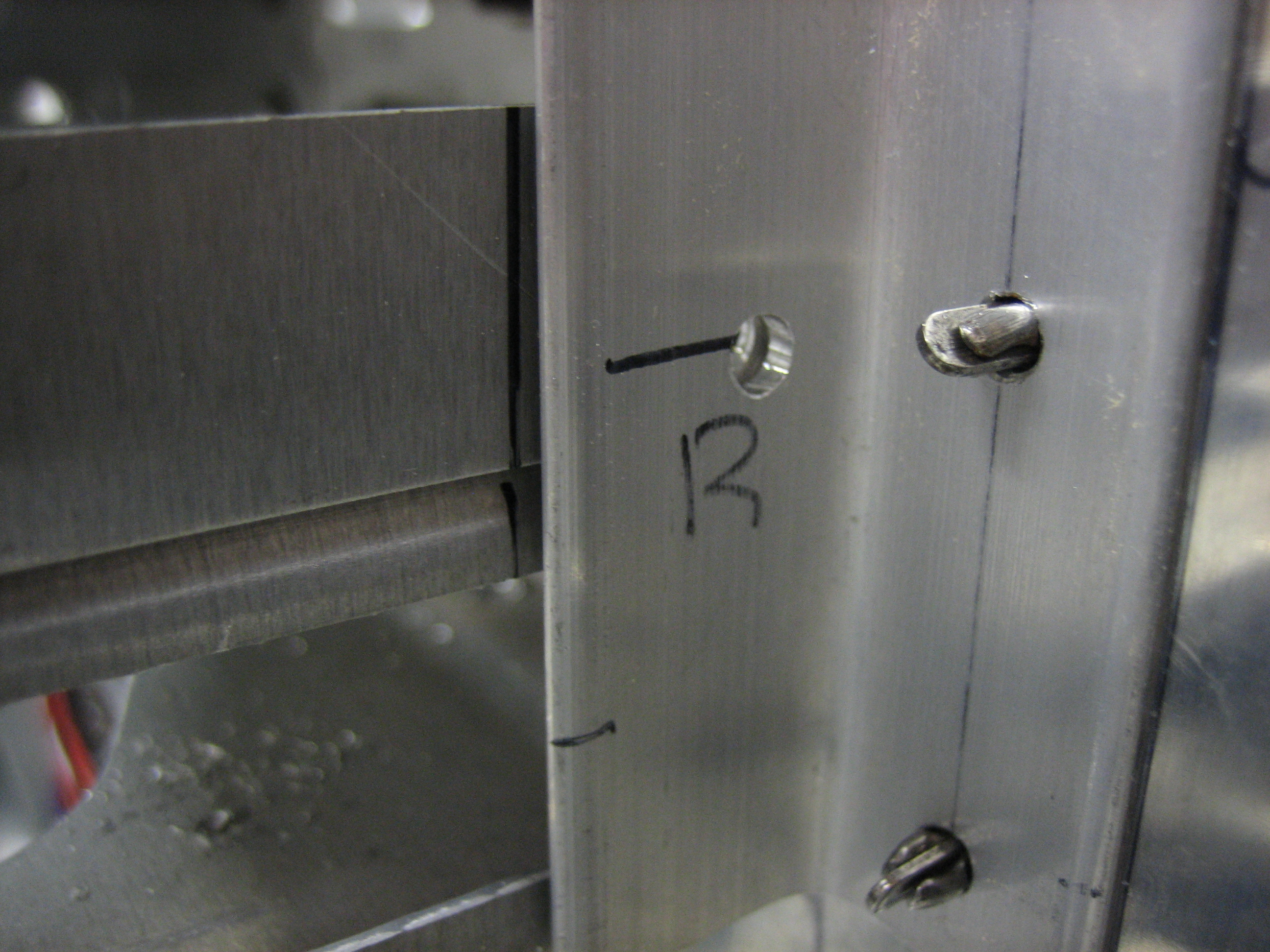
I fabricated a little standoff to anchor the alt air cable at the aft end of the baffles.  It’s just a short piece of 0.063″ aluminum with a nutplate riveted to the back.  It has a hole in the other end and is installed behind the upper adel clamp.

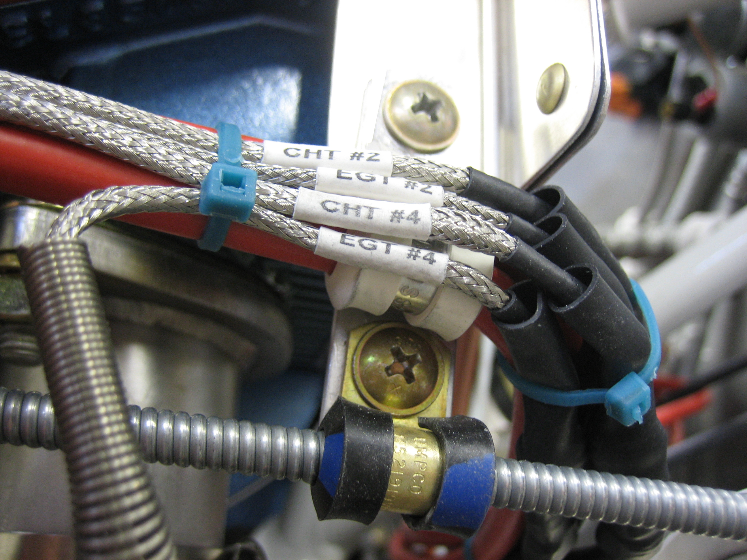
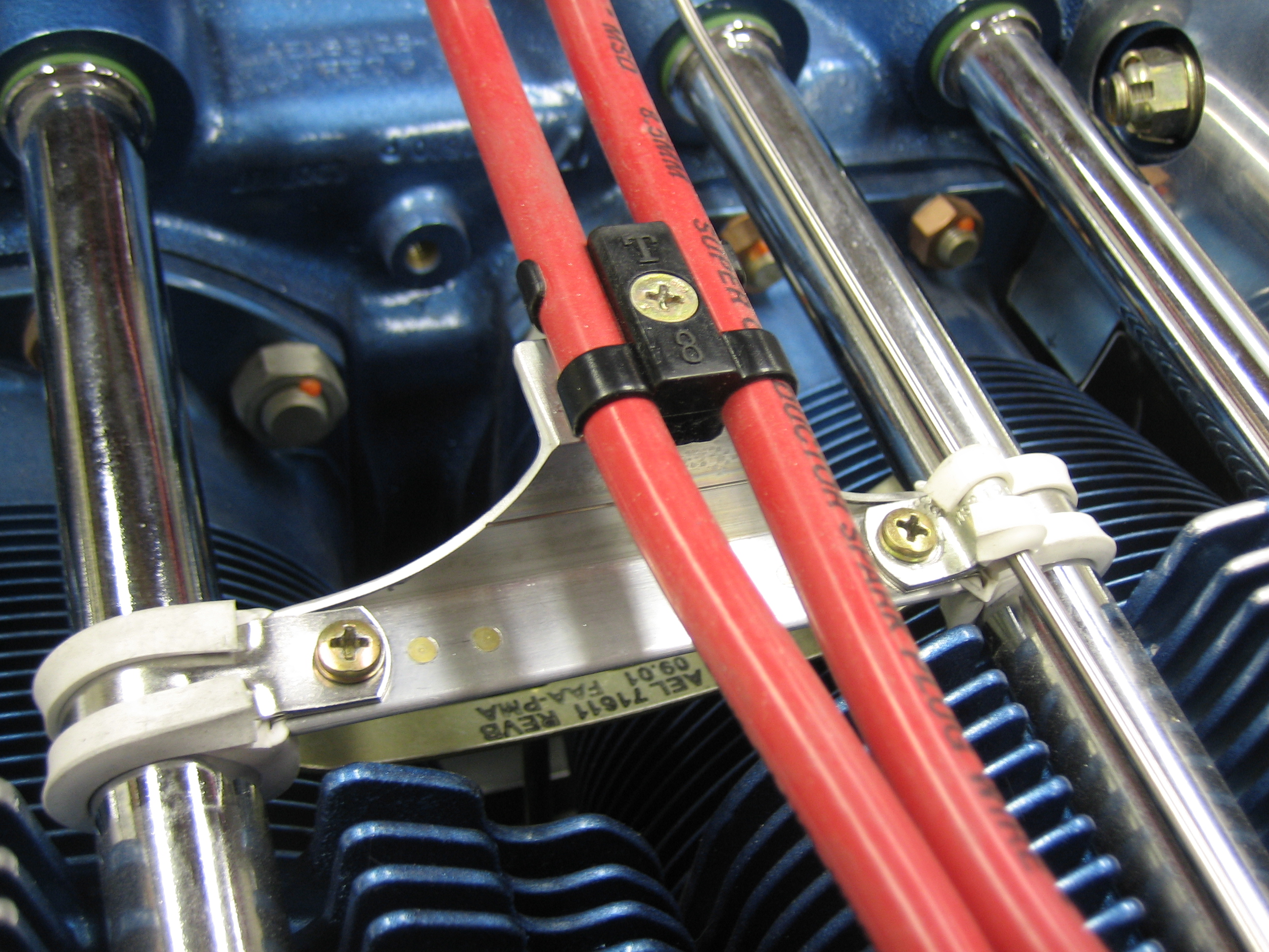
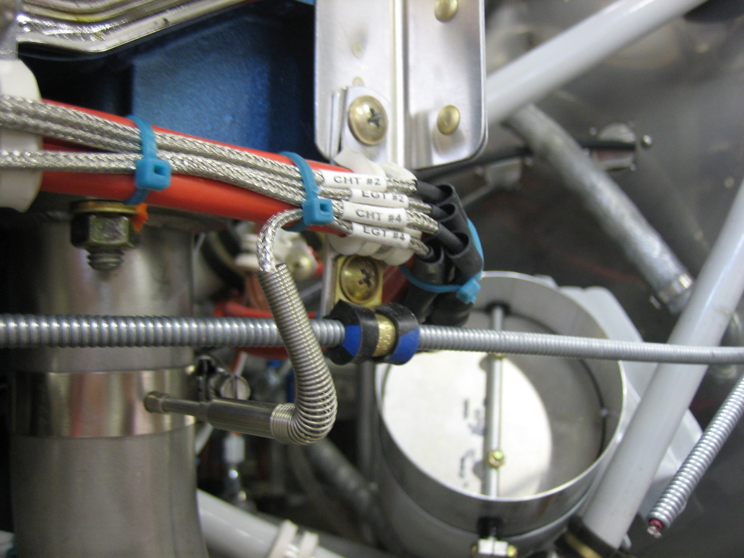
Here you can see that this keeps the cable well clear of the EGT probe as well as the wire bundle above.

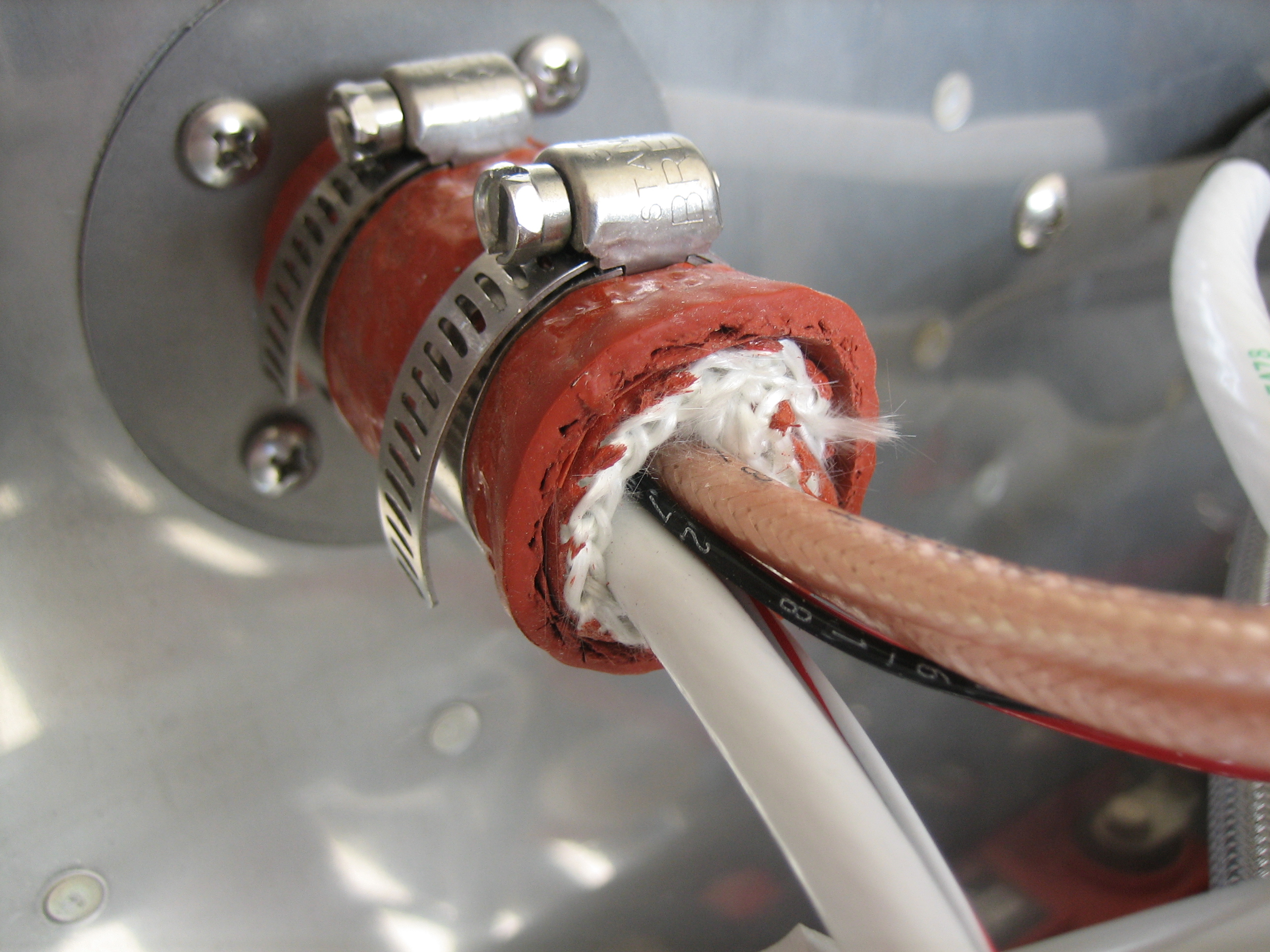
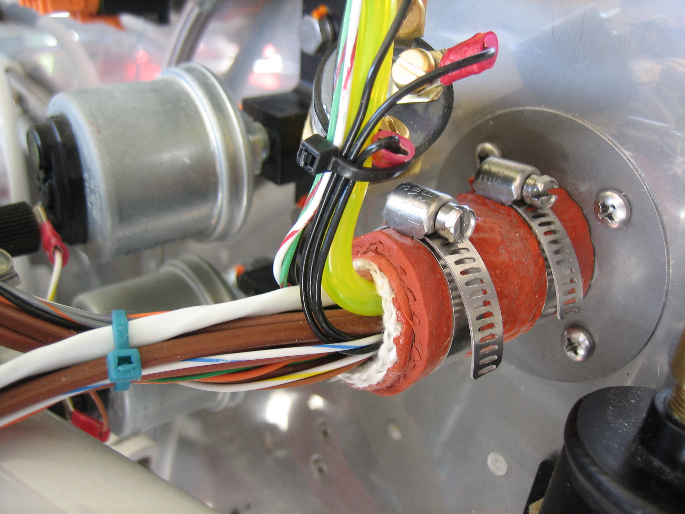
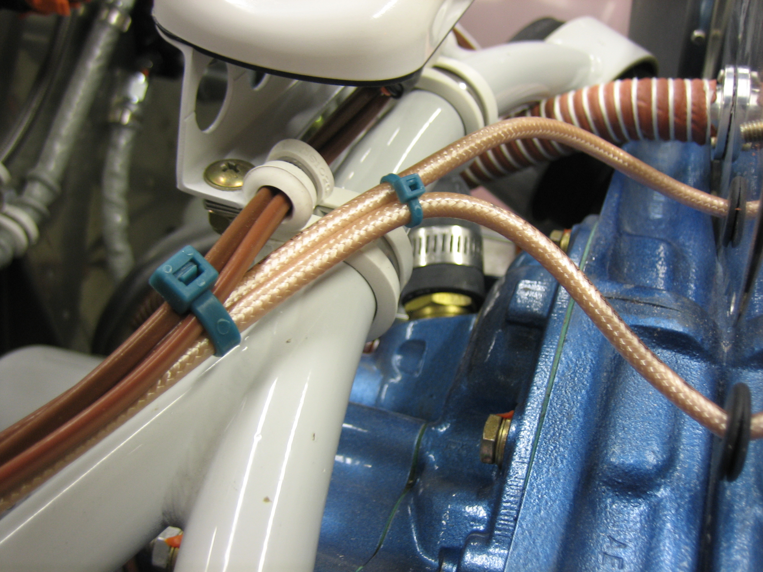
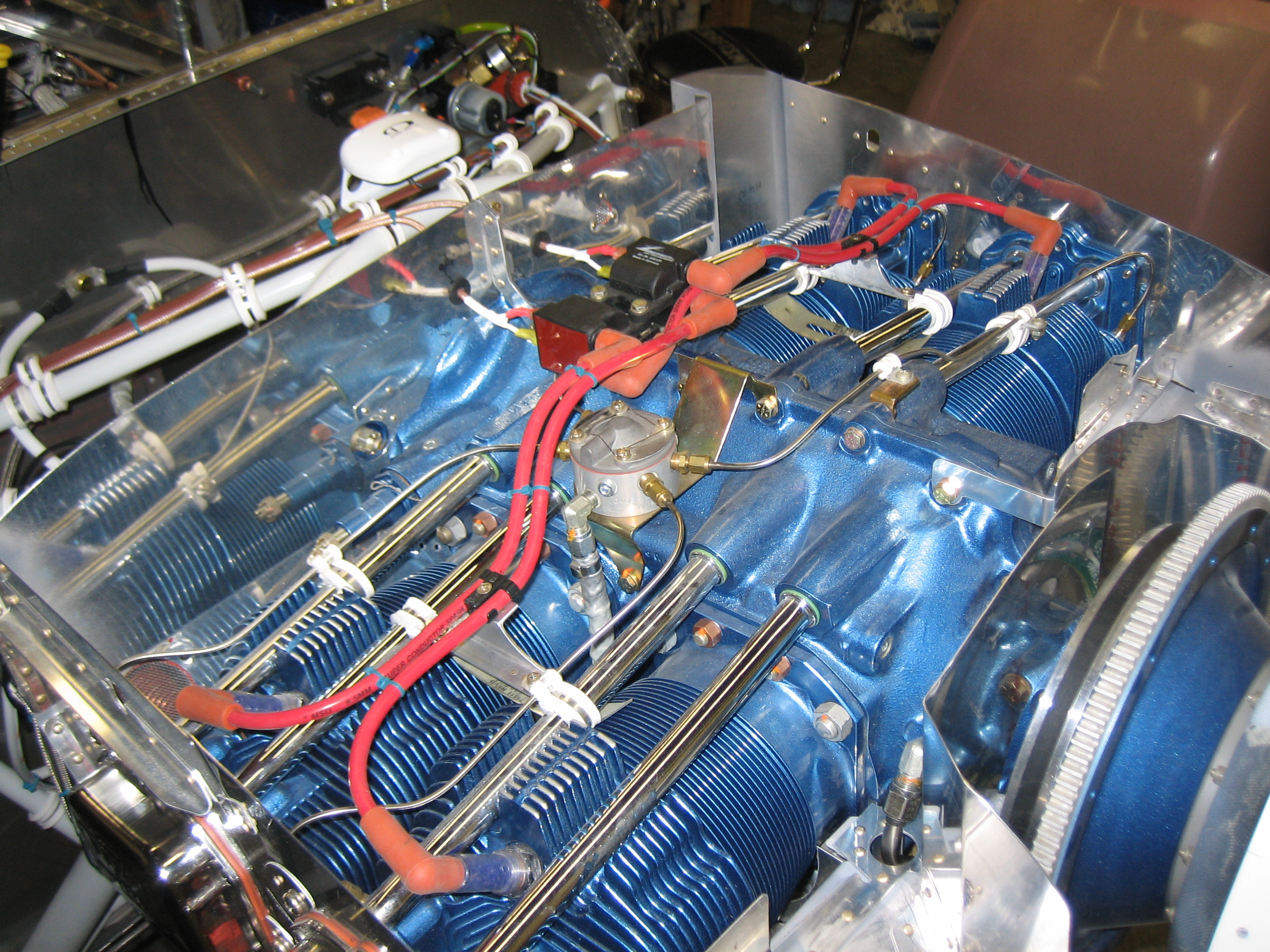
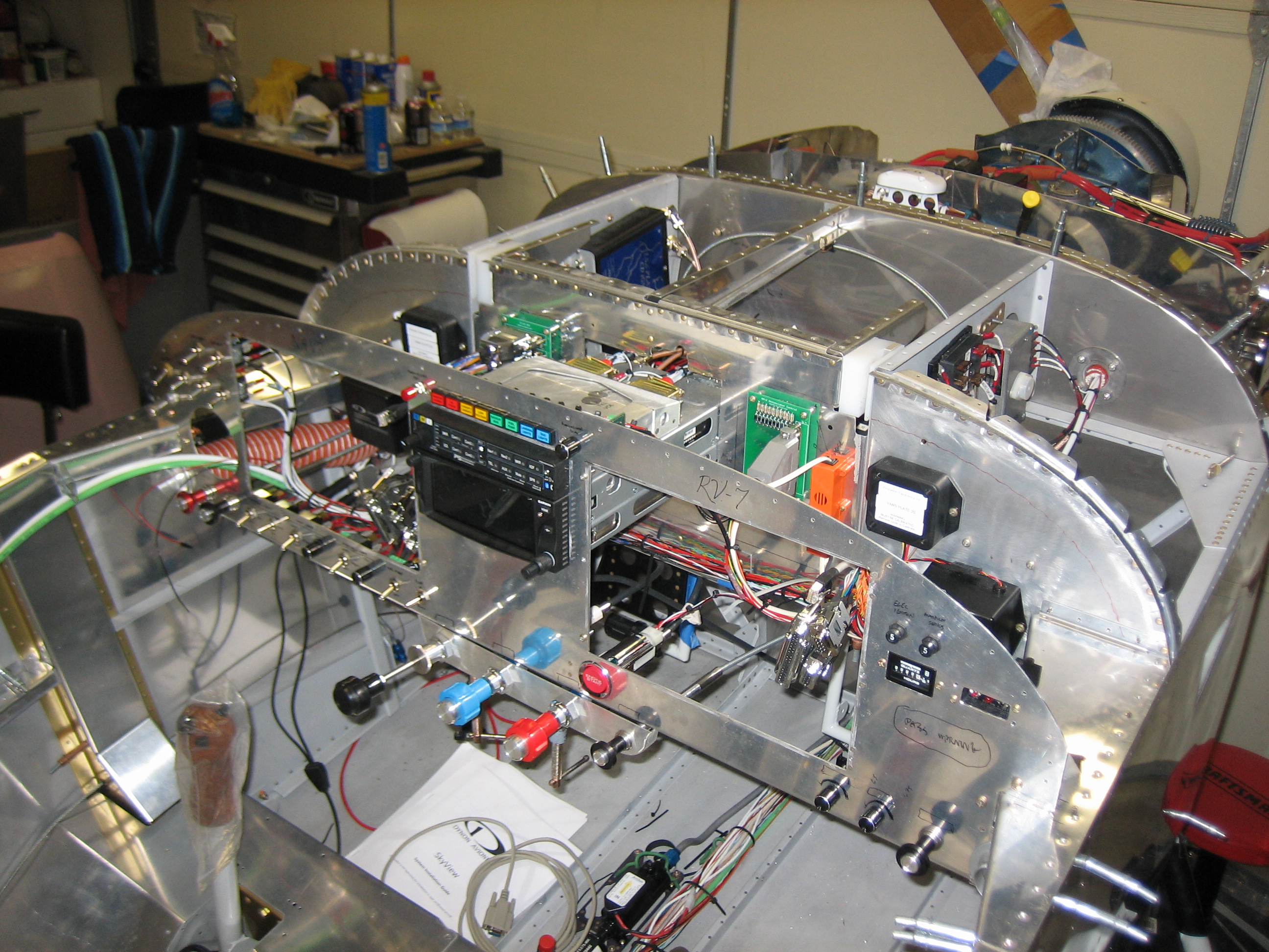
I also rerouted the manifold pressure wires to run along the firewall instead of directly out to the engine mount.  They’re better supported now and less likely to get snagged while working on the plane.

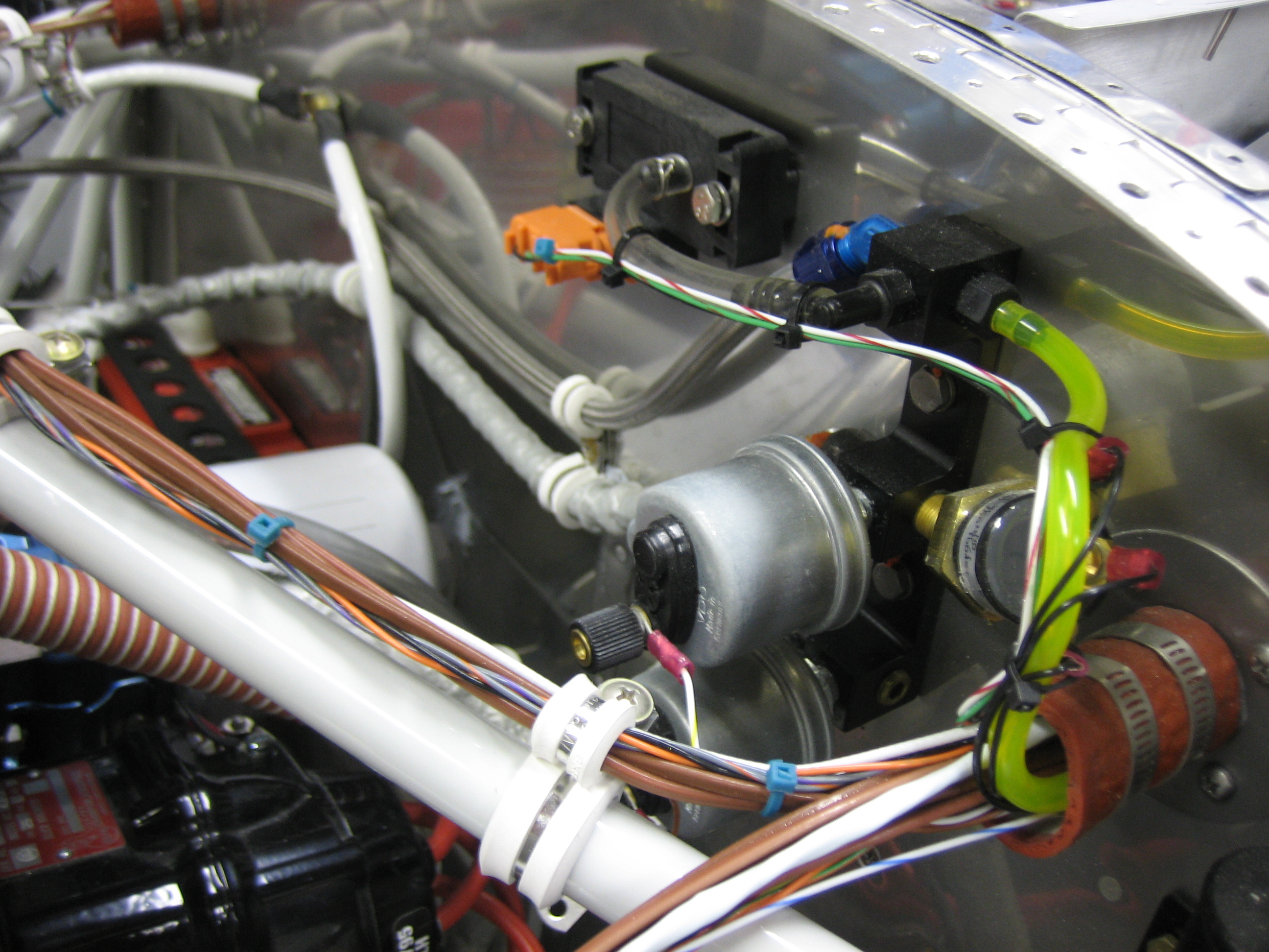
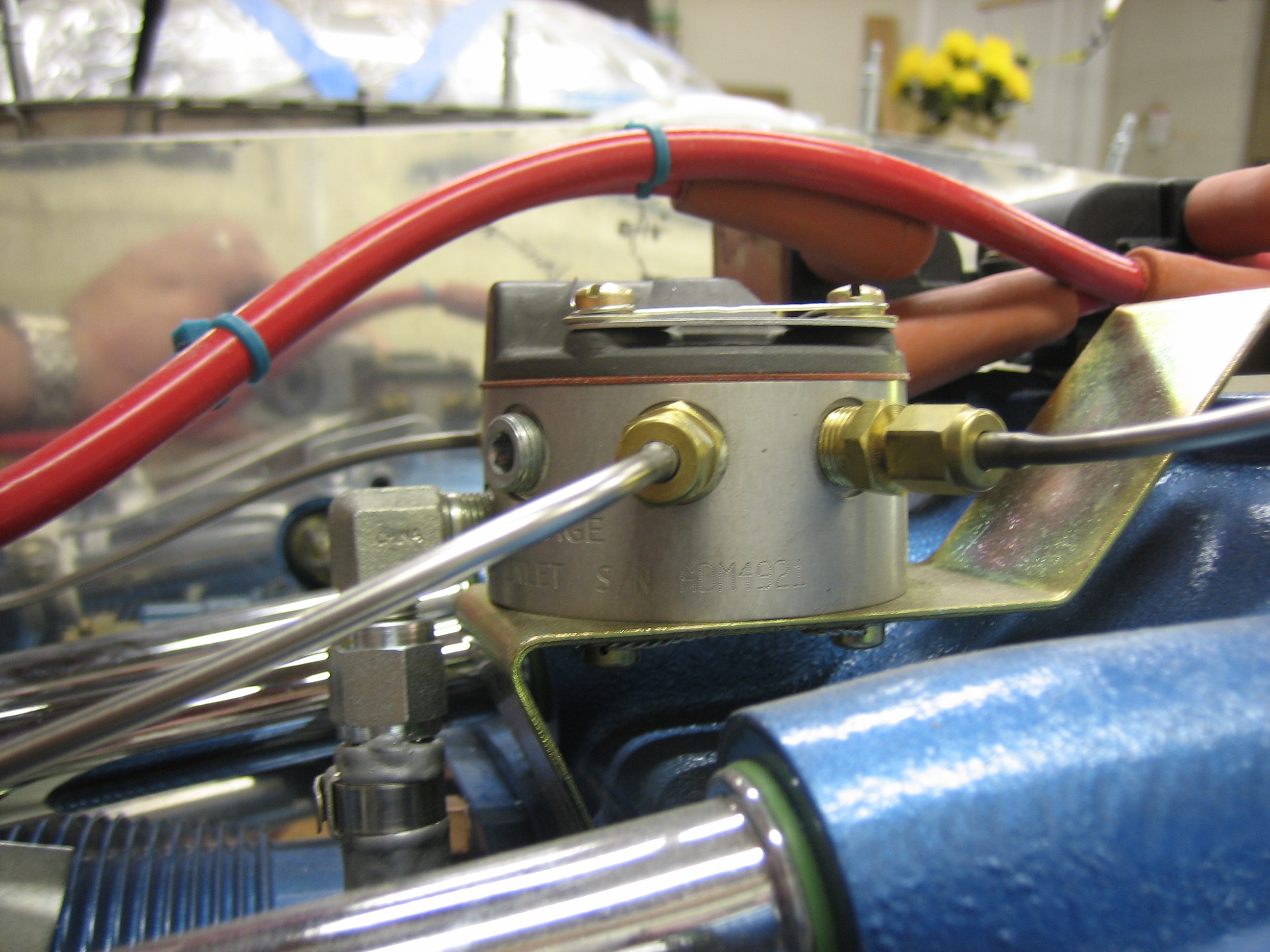
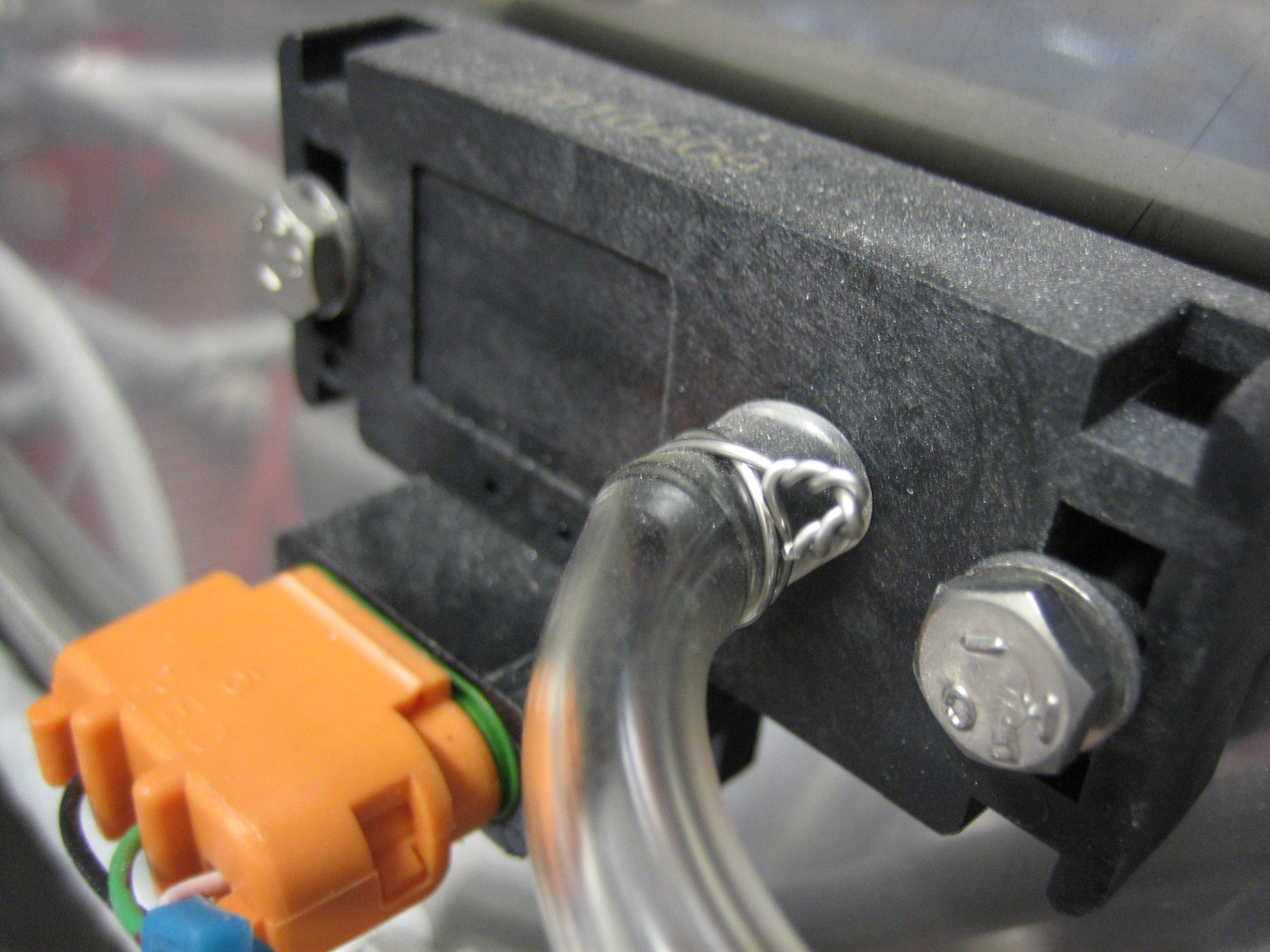
The tube going to the Dynon manifold pressure sensor was a little loose (although it was tight when I originally installed it).  I used a couple of wraps of safety wire to tighten this up nicely.

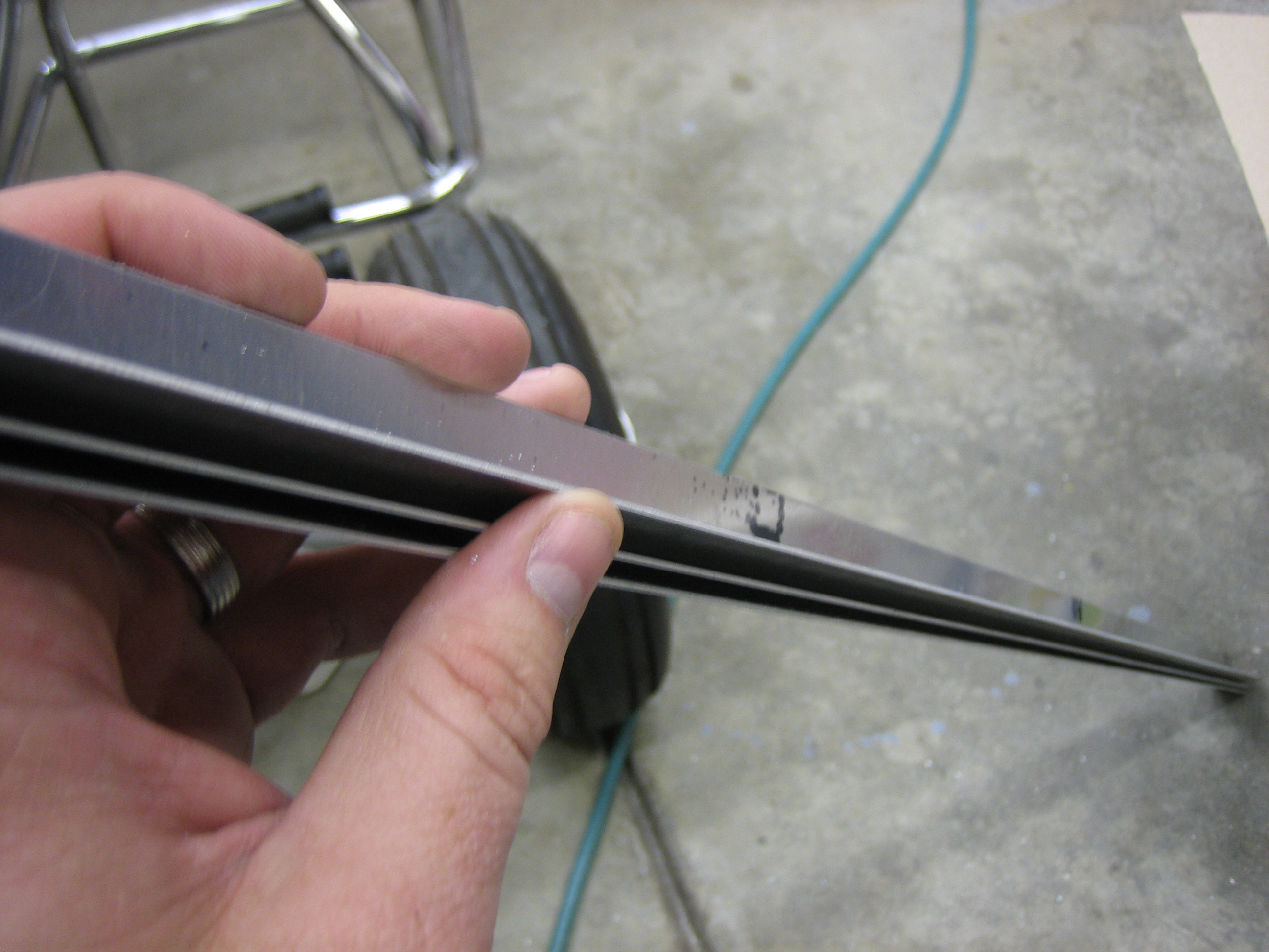
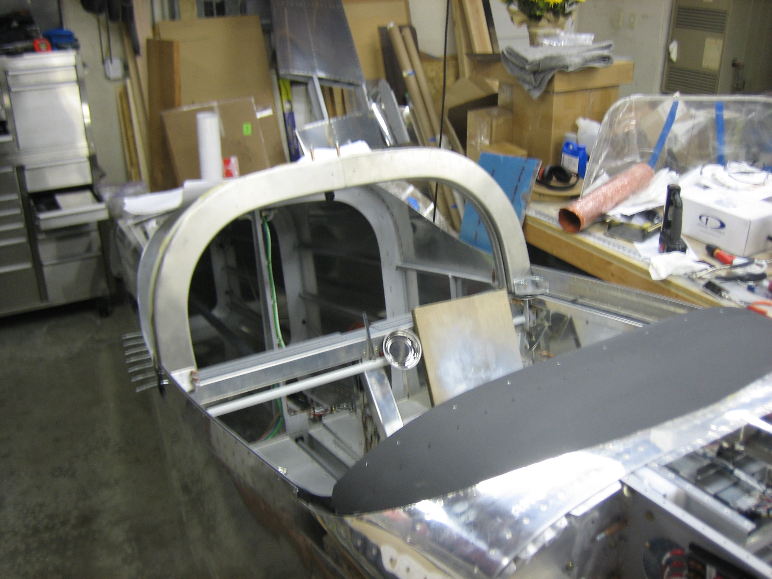
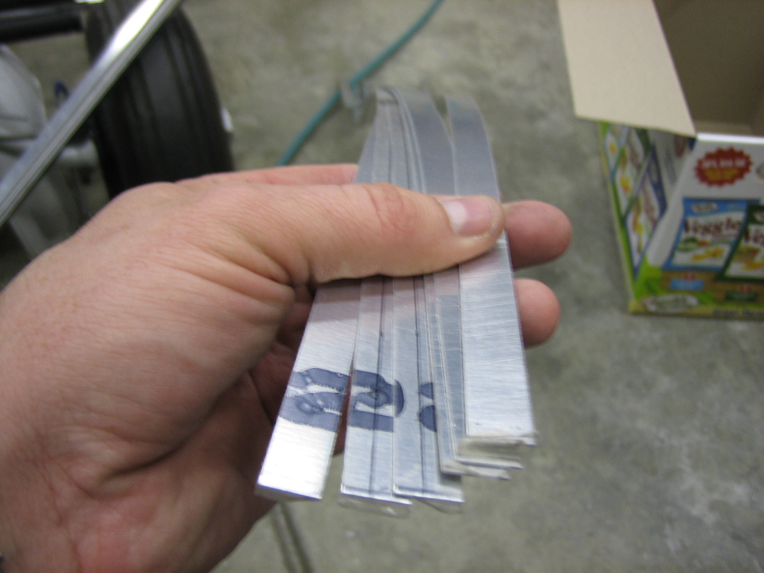
To space the wingtip hinges away from the skin, I need a couple of 0.024″ spacers under each hinge.  I cut a few of these by hand, but that was a real pain and it really twisted them up.  I recently got a lifetime membership to the TechShop, so I ran down there and used their shear to cut 6 more 1/2″ wide strips.  Even counting the drive, this was way faster than doing this with snips (not to mention how much easier it was on my hands).

While I was there, I cut some 1.5″ wide strips of 0.040″ and bend them to 90º on the bending brake.  These will be installed on the baffles to provide a mounting flange for the plenum over the engine.

Sealed Firewall Pass-Throughs

I’m done running wires through the firewall (I hope), so I sealed up the pass-throughs.  The wires are wrapped tightly with some silicone impregnated fiberglass and then wrapped that with silicone tape.  The silicone impregnated fiberglass sleeve is then slid over the whole mess and squeezed tight with the worm clamps.  The back one tightens against the flange and the front one tightens against the wires.  This is the one on the right side of the firewall.

And here’s the one on the left side of the firewall.

Hooked up Electronic Ignition

I cut the high-tension leads down and installed the fast-on connectors.  You can see that I used some large rubber grommets that allow me to pull the fast-on connectors through the baffles so I can remove them.

After that, I fired up the ignition and phased the coils.  The left one (right in this picture) fires the #1 and #2 cylinders, and the right one fires the #3 and #4 cylinders.

I added a couple of zip ties to the high tension leads so that they won’t rub on the engine mount.  You can see that there is some slack in these lines to allow for engine movement.

Fabricated Upper Ignition Wire Supports

I fabricated a couple of supports for the upper ignition wires.  I’ll probably drill a couple of lightening holes to shave off a little weight.

The spark plug wire supports screw to the upper flange of the support.

Here’s where they will be installed.  They’re clamped to the inner push rod tubes with a couple of adel clamps.

After installing both and adding some Tefzel zip-ties, the wires are really nicely supported and spaced apart.

The wires arc up slightly from the coils and curve over the fuel spider.  There’s over 1/2″ of clearance and the wires have to be pushed down pretty firmly to deflect anywhere near the spider.

Modified Canopy Safety Latch

The canopy safety latch pivots in a UHMW block and is used as a secondary latch in case the primary canopy latches pop open.  It’s also used to prop the canopy open by resting the longer flange on top of the roll bar.  The problem is that because the latch is free to rotate, vibration can cause it to spin around and not stay where you put it.  Worse, there has been at least one case where someone shut their canopy and the safety latch pivoted and caught under the roll bar, preventing them from opening the canopy.  There are a couple of approaches that builders have used to prevent this.  One is to simply squeeze the tube that passes through the UHMW block too increase the friction.  Another is to allow the safety latch to slide up and down in the UHMW block with a spring to keep it up.  The pilot would then need to pull it down to pivot it under the roll bar.  For various reasons, I didn’t like either of these approaches.  I ended up deciding to modify the latch so that there are detents when rotating (one in each of the latched and unlatched positions).  I stopped by the TechShop and used their milling machine to machine some grooves into the shaft.

I used a 3/16″ diameter ball end mill to machine some grooves 0.030″ deep in the shaft 90º apart.

I then drilled a hole in the side of the UHMW block in line with the center of the shaft.  The hole contains a 3/16″ ball bearing, a spring, and a set screw to adjust the pressure on the spring.

This works beautifully.  The handle positively stops in the unlocked position (parallel to the block).

…and in the locked position (perpendicular to the block).  I’m very happy with how this turned out.

Finished Fabricating Canopy Safety Latch

I drilled the mounting holes in the UHMW block and countersunk them for AN509-10R18 screws (which probably have to be replaced by R19 screws).

I then drilled a 0.130″ hole for a MS24665–359 cotter pin.  This seems rather thick, but if the main canopy latch fails, the all of the force trying to pull the canopy open is carried in shear by this cotter pin.

Afterward, I drilled and installed the block to the canopy frame.  I’ll install the cotter pin for good once I’ve painted everything.

Started Disassembling Cabin Area

I removed the canopy frame and started taking out the avionics.  I still need to trim and install the ribs that tie the instrument panel to the subpanel, so I spent a little time determining how to do that.  I also tidied up the wiring harness on the right side.  After the panel comes out, it won’t go back in until the cabin area is painted and the panel is painted and labeled.