Worked on Left Longeron

I started tonight by making a template (shown in the middle here).  I glued the bending template from the RV-7A page to a piece of 1/4″ MDF; cut it out and sanded to the line.  I then spent about an hour fine tuning the bend on the left longeron.

Here is the template sitting on the left longeron.  As you can see, the far end (rear end) still needs a little fine tuning, but the rest of the bend is within 1/32″ or so and the longeron is pretty close to flat and zero twist.  A lot of builders complain that bending the longerons are really frustrating (and Van’s instructions describe it as maddening), but I haven’t found the process too bad at all.  If you take your time and make gradual bends, it’s pretty straightforward.

Worked on Tailcone

The tailcone has six stringers that must be cut to length.  The ends also need some shaping, but fitting them to the tailcone now will allow me to shape the ends to fit the bulkheads precisely.

Next up, I fit the tailwheel spring mount between the last two bulkheads.  This will eventually be bolted to both of them.  These are both double bulkheads, and they’re riveted to both the side and bottom skins, the side stringers and the longerons.  Needless to say, this will be a phenomenally strong part of the airplane.

This skin needs an arched section removed to allow the tailwheel spring mount to stick through.  The plans provide a template for the shape of this.  I traced it onto a sheet of paper and transferred it to the tail skin.  It was pretty close, but required a little further sanding right at the rear edge of the mount.

I then clecoed the tail skin to the bottom skin and slid the stringers into place.  I’ll trim the stringers tomorrow and then the side skins can be clecoed on.

Assembled Tailcone

I went out this morning before work and drilled the tailwheel spring mount to the F-711.  It took quite a while to ensure that the mount was centered, square, and the tailwheel was exactly vertical.

F-712 gets a couple of keeper rivets to hold the mount in place until the bolt holes can be drilled in conjunction with the vertical stabilizer rear spar.

Unfortunately, one of the holes came out slightly under the recommended edge distance of 1.5D (12/32″ in this case).  I need to run this by Van’s and see if they think this is an issue.

Update: Ken Scott at Van’s said not to worry about 1/32″, especially in steel.  “Build on” as they say…

I clecoed the tailcone together.  Getting the stringers in gets a little tough once all of the bulkheads are in place, but I eventually got it.  The ends of the lower four stringers need notches cut in each end to clear the bulkheads.

Here’s a shot looking down the tailcone from the other end.  The vertical rib connecting the top an bottom of the closest bulkhead as well as the horizontal rib that connect the closest two bulkheads are supposed to be off center.

The holes in the tail skin don’t even come close to lining up with the holes in the side skin.  I need to do a little research on this to see how to get these to align.  I can’t just pry them into alignment since there is a stringer right on the other side of these holes that would prevent inserting a cleco through the hole after aligning.

Fit Tail Skin

Like I mentioned yesterday, the holes in the tail skin didn’t come close to aligning to the side skins.  I couldn’t pry the skins into alignment and hold them with clecos because there is a stringer right behind the row of rivets along the bottom of the side skin and the stringers don’t have any holes in them.  The fix turned out to be relatively simple.  Remove the side skin, match drill the lower stringers through the holes that will be shared with the tail skin, then cleco the tail skin back on.

Getting the tail skin out without removing all of the bulkheads required removing a fair number of clecos at this end of the fuselage.  Here, I’ve match drilled the lower stringers from F-710 back.

Now the F-779 tail skin can be fit.  Putting in the clecos on the first side was pretty easy, but the second side was pretty tricky.  The fit is really tight in this area, so it takes a fair amount of force to get the holes to align.  I worked my way from the front to the back one hole at a time and eventually got everything aligned nicely.

It’s hard to see here, but I hung a plumb bob through the top tooling hole of F-712 and shimmed the tail until the string bisected the bottom tooling hole.

I then hung a second plumb bob from the upper tooling hole in F-706 and shimmed the front until this was centered in the opening.  It’s too late to start drilling tonight, so I’ll start this tomorrow.

Drilled Tailcone Stringers

Jenn helped me raise the tail so that the plumb bobs would be more accurate and then I reshimmed the tailcone so that there was no twist.  I then drilled every fourth hole down the stringers (the horizontal rows of clecos in this picture).  The tailcone is pretty stiff now though it can still be flexed a little bit until the aft top deck is riveted on.

Drilled Tailcone

No pictures tonight as it would look just like last night.  I drilled all of the holes in the tailcone that needed to be drilled right now.  This included the stringers and bulkheads (except for the frontmost one (F-706) and the top row of holes where the longerons are attached.  Drilling the bottom was a pain because I had to lie on a creeper and was absolutely covered with aluminum shavings by the time I was done (wear a full face mask if you want to keep them out of your eyes).

Finished Aft Fuselage Fabrication

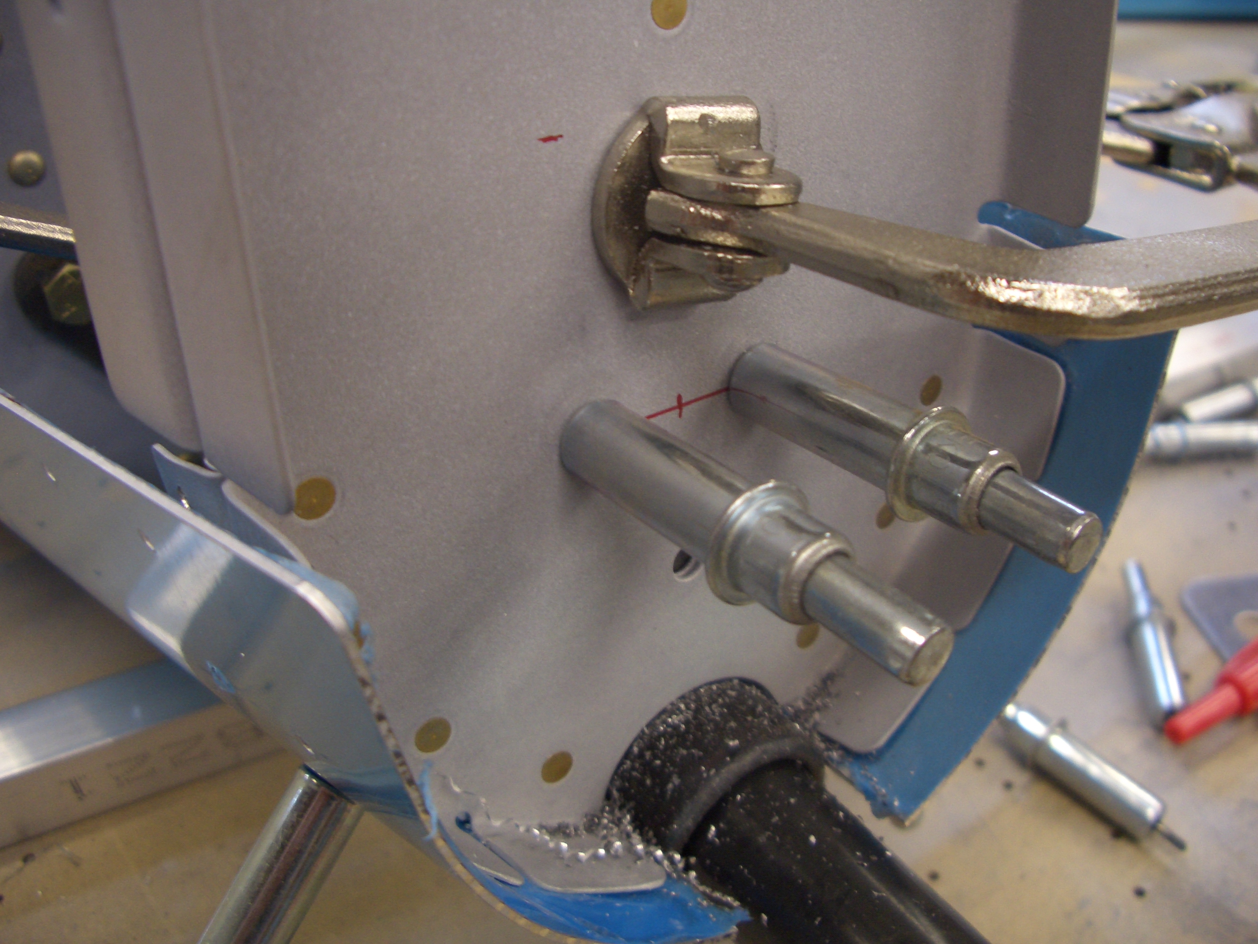
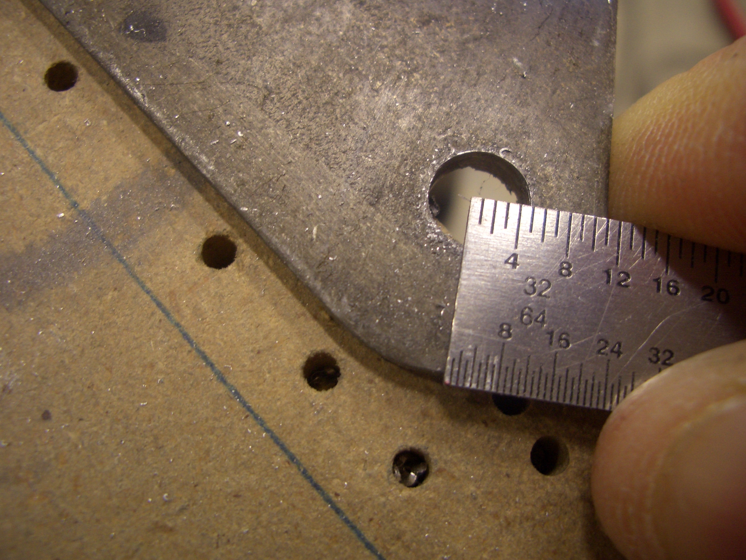
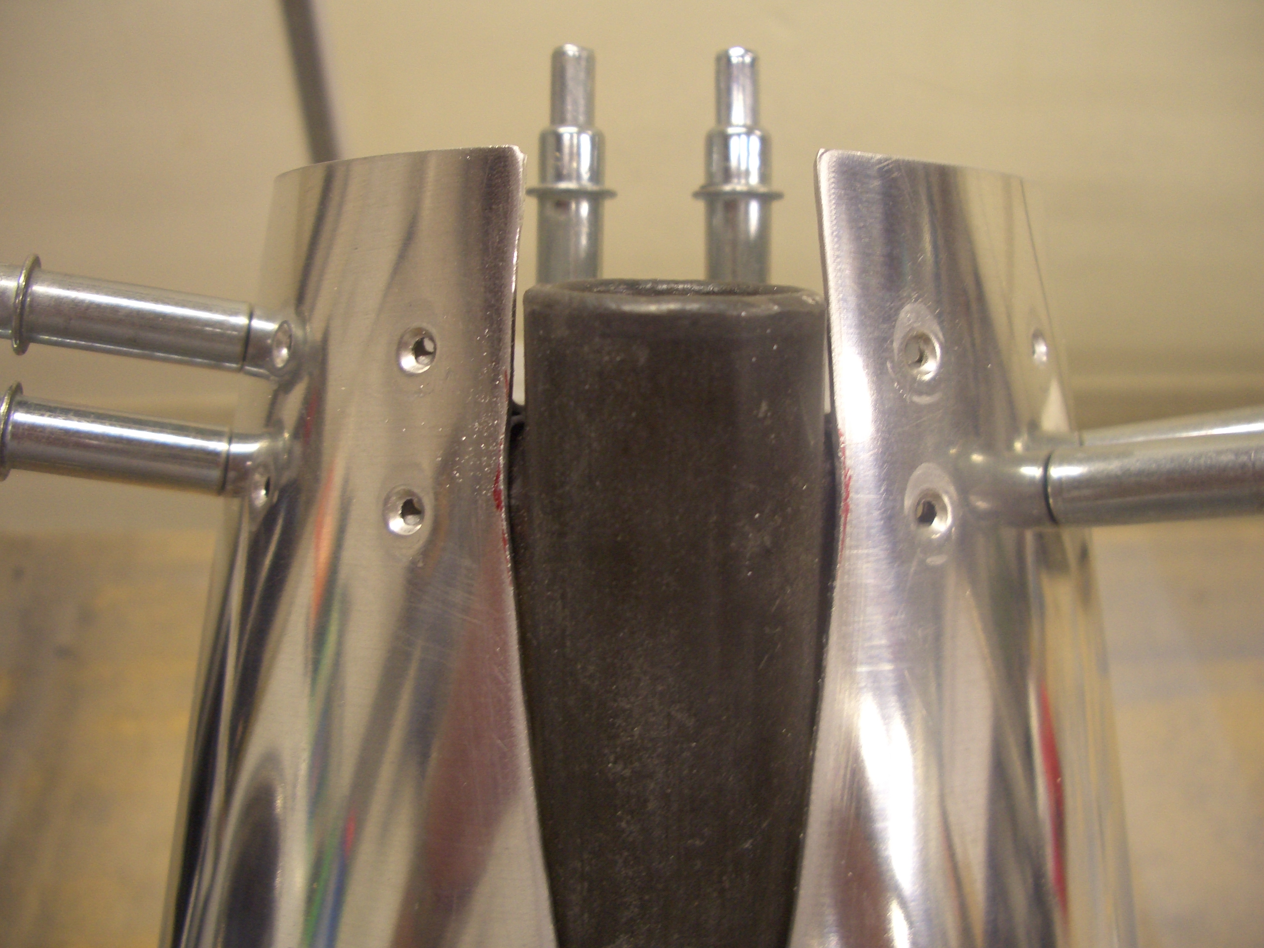
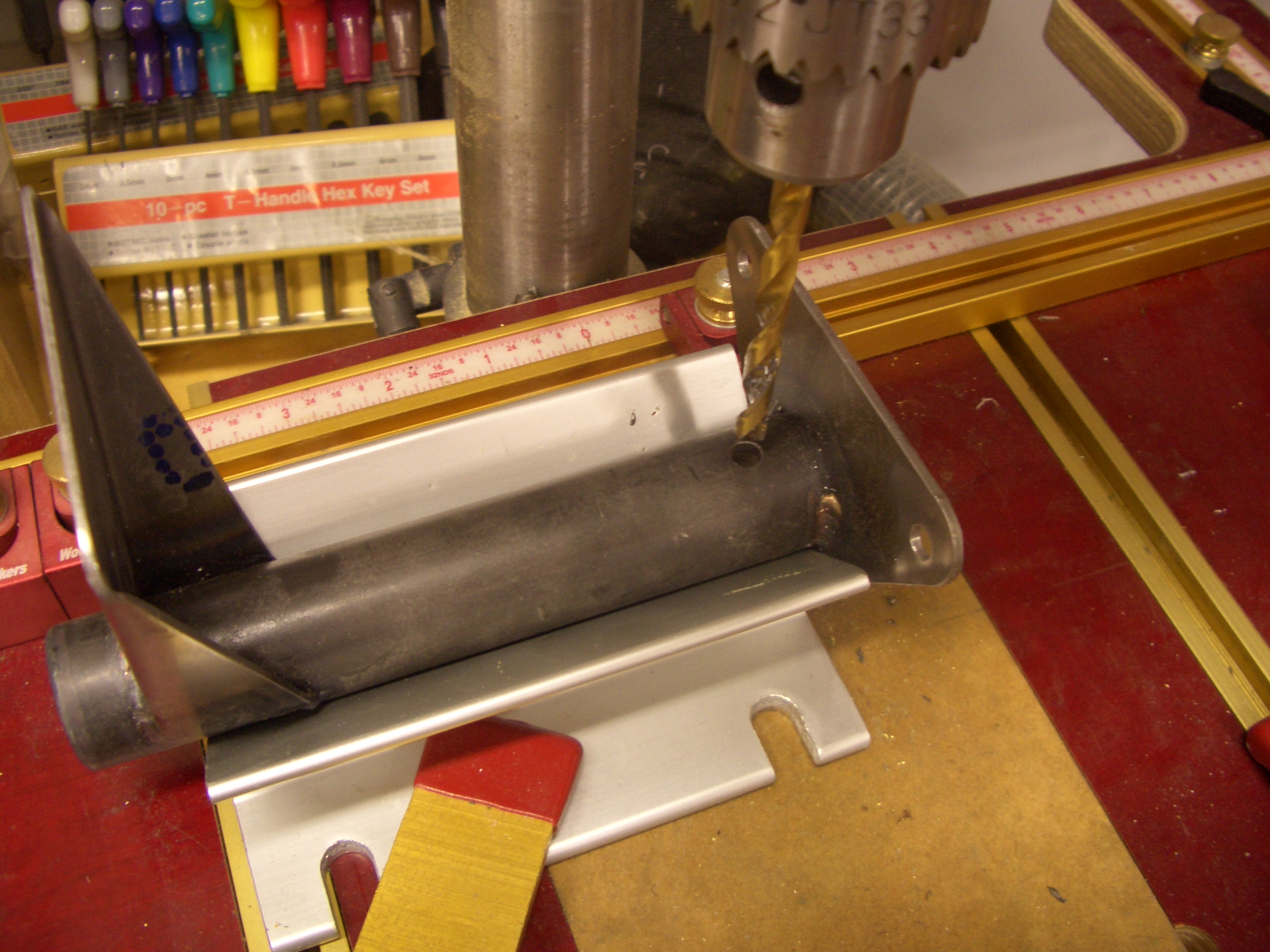
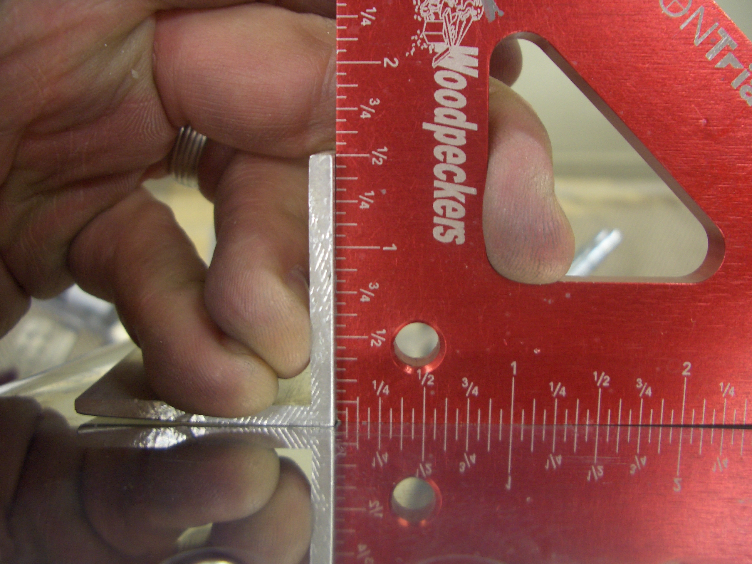
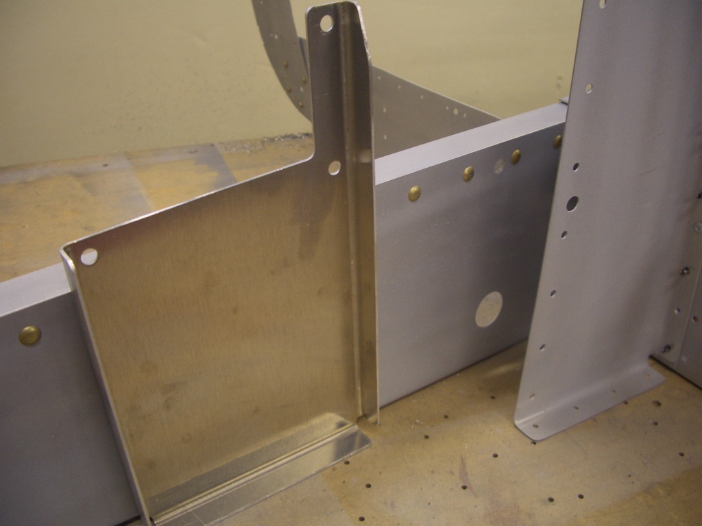
I had a couple of tasks to take care of before disassembling the aft fuselage.  First up is to mount the autopilot pitch servo mounting bracket.  The forward edge of this has to be 3.43″ from the center of the 1/4″ pivot hole for the elevator bellcrank.  This required drilling out three rivets so the mounting plate could sit flush.  If you’re installing a dynon autopilot, just leave these rivets out from the beginning and save yourself the time.

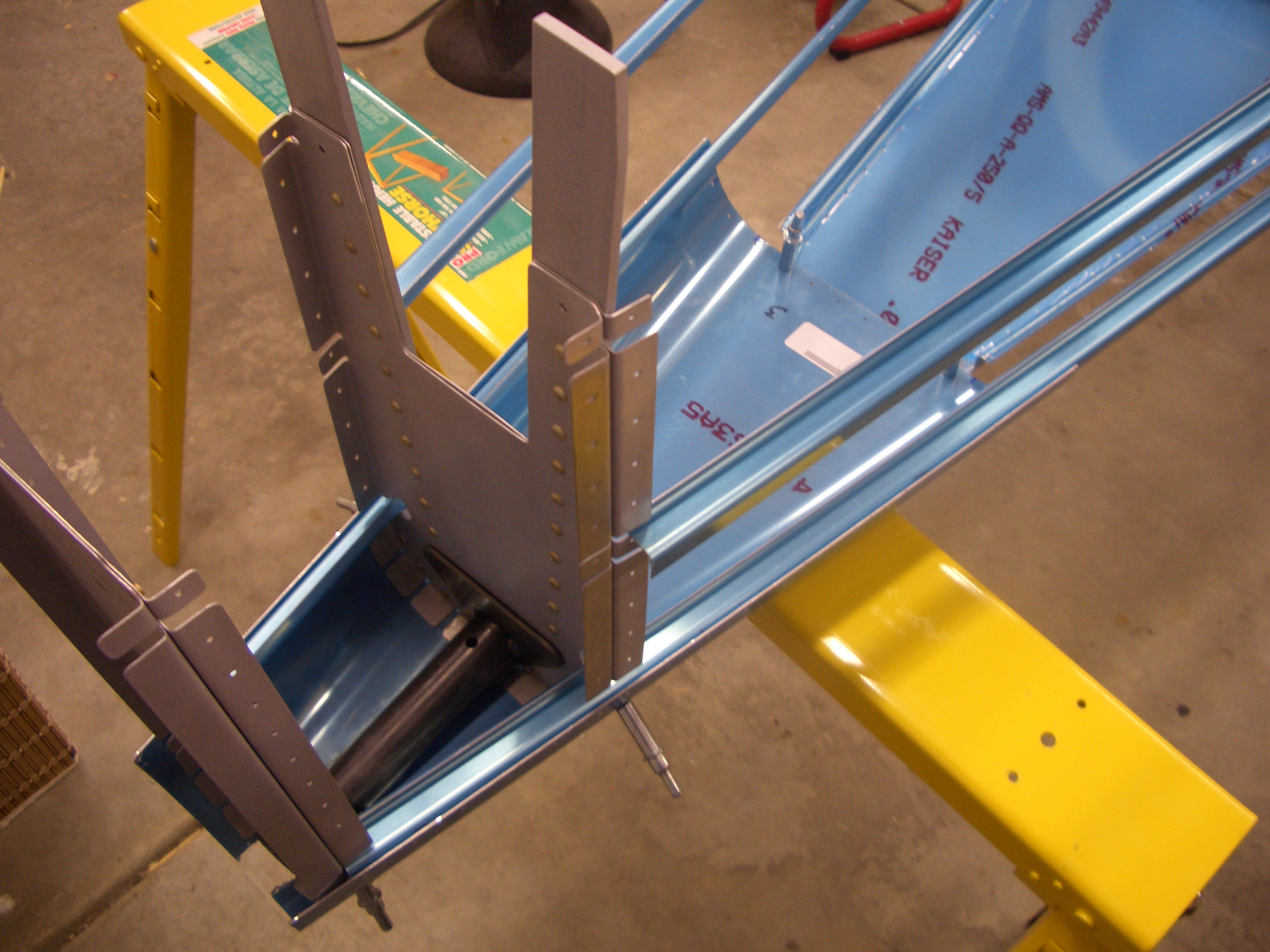
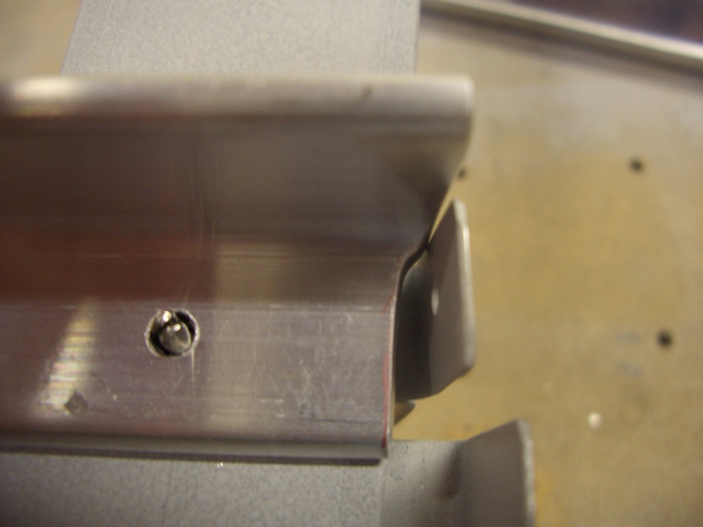
Here’s how the bracket sits against the rib.  The flange on the bottom can be cut off or drilled to the skin (which I’m doing).

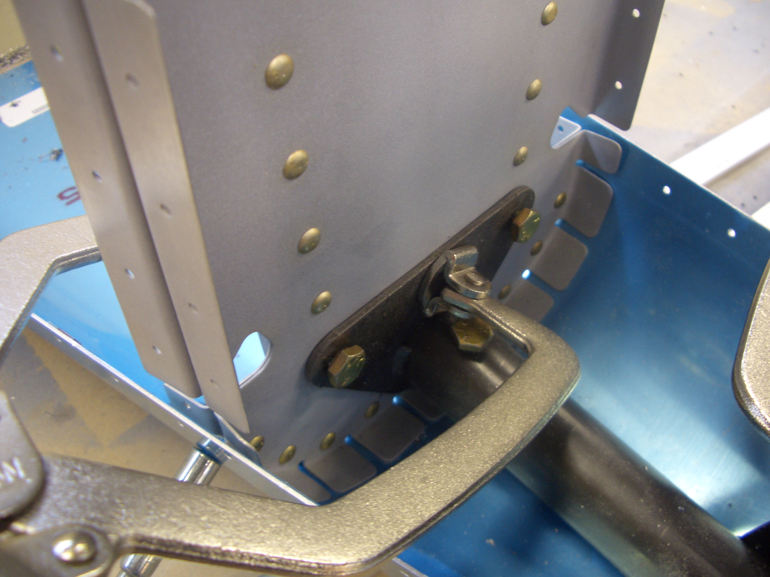
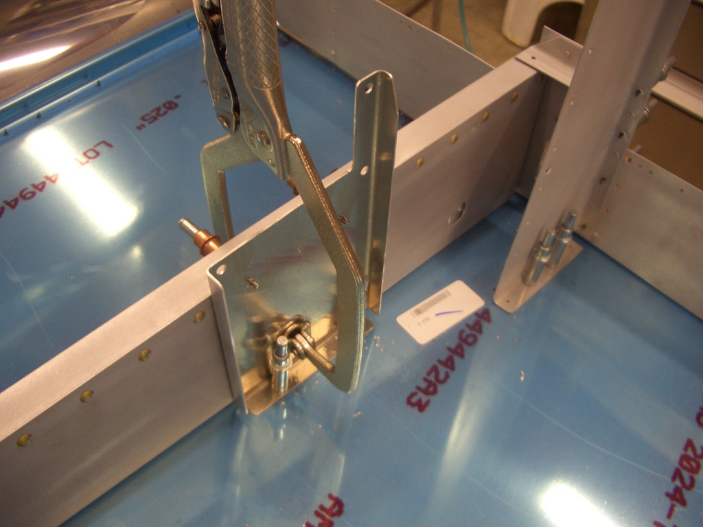
After match drilling the bracket to the rib, I laid out for rivet holes aligned with the ones in the rib (as if aesthetics matter on the bottom of the aircraft).

After clecoing the structure back to the bottom skin (and using a clamp to keep the bracket tight against the rib), I match drilled the skin to the bracket.

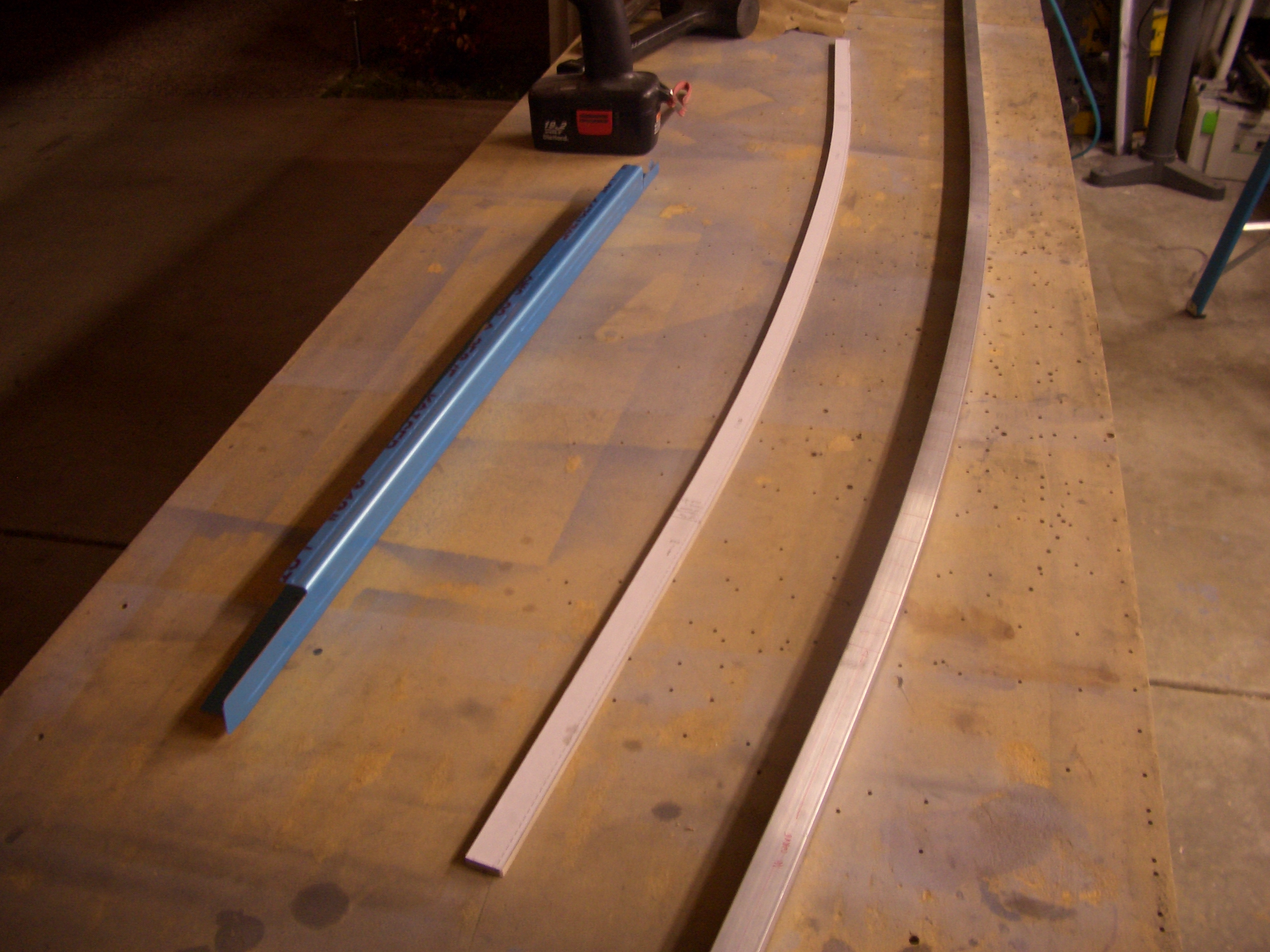
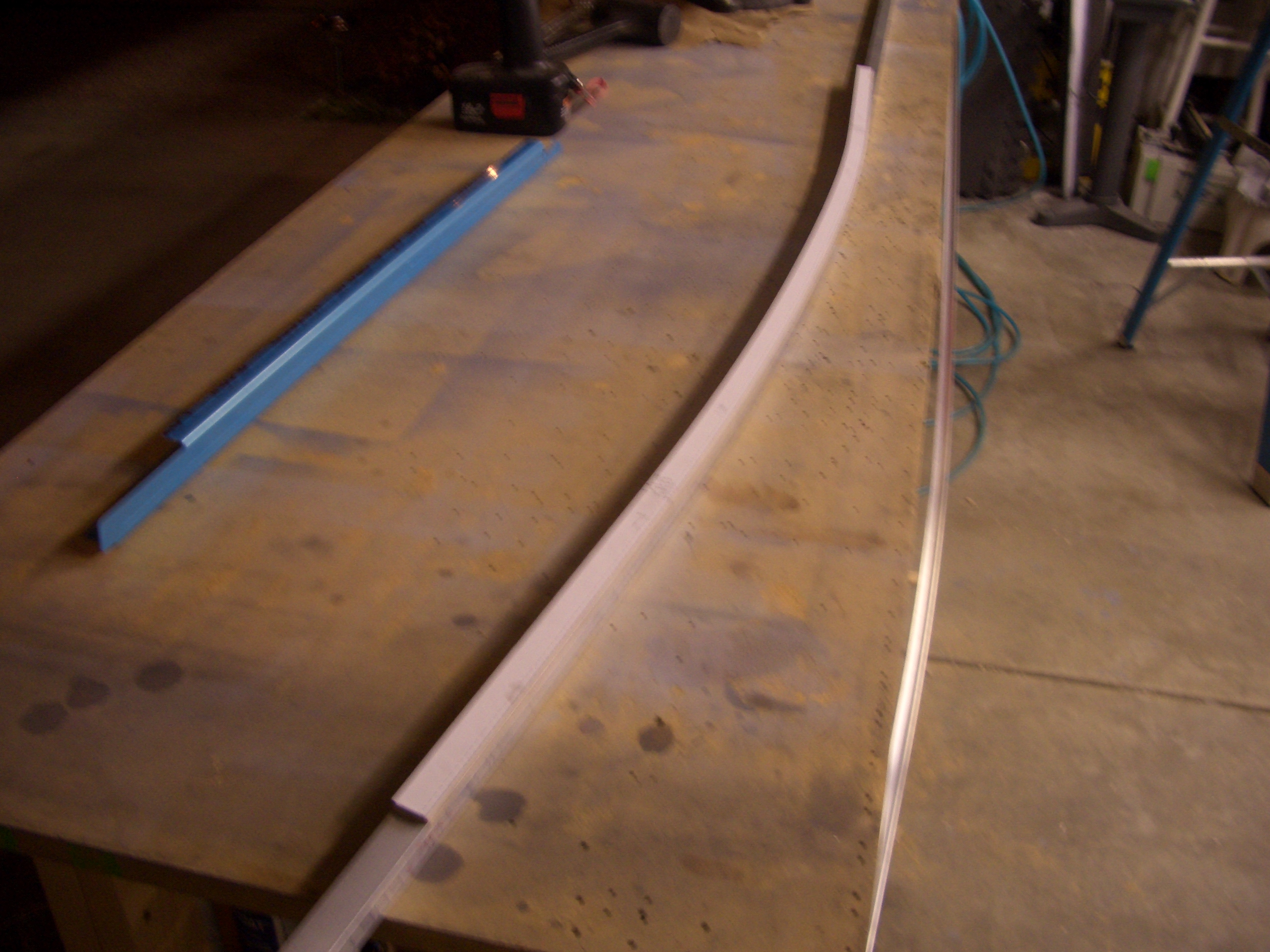
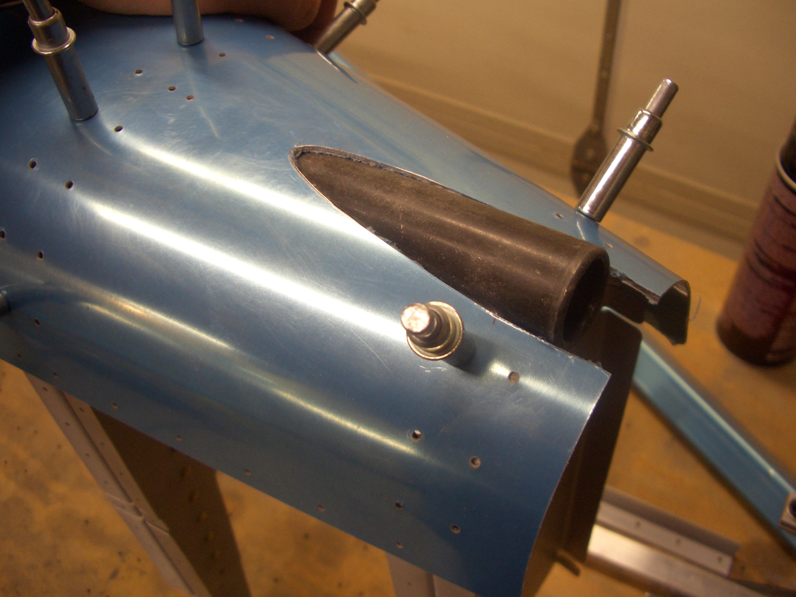
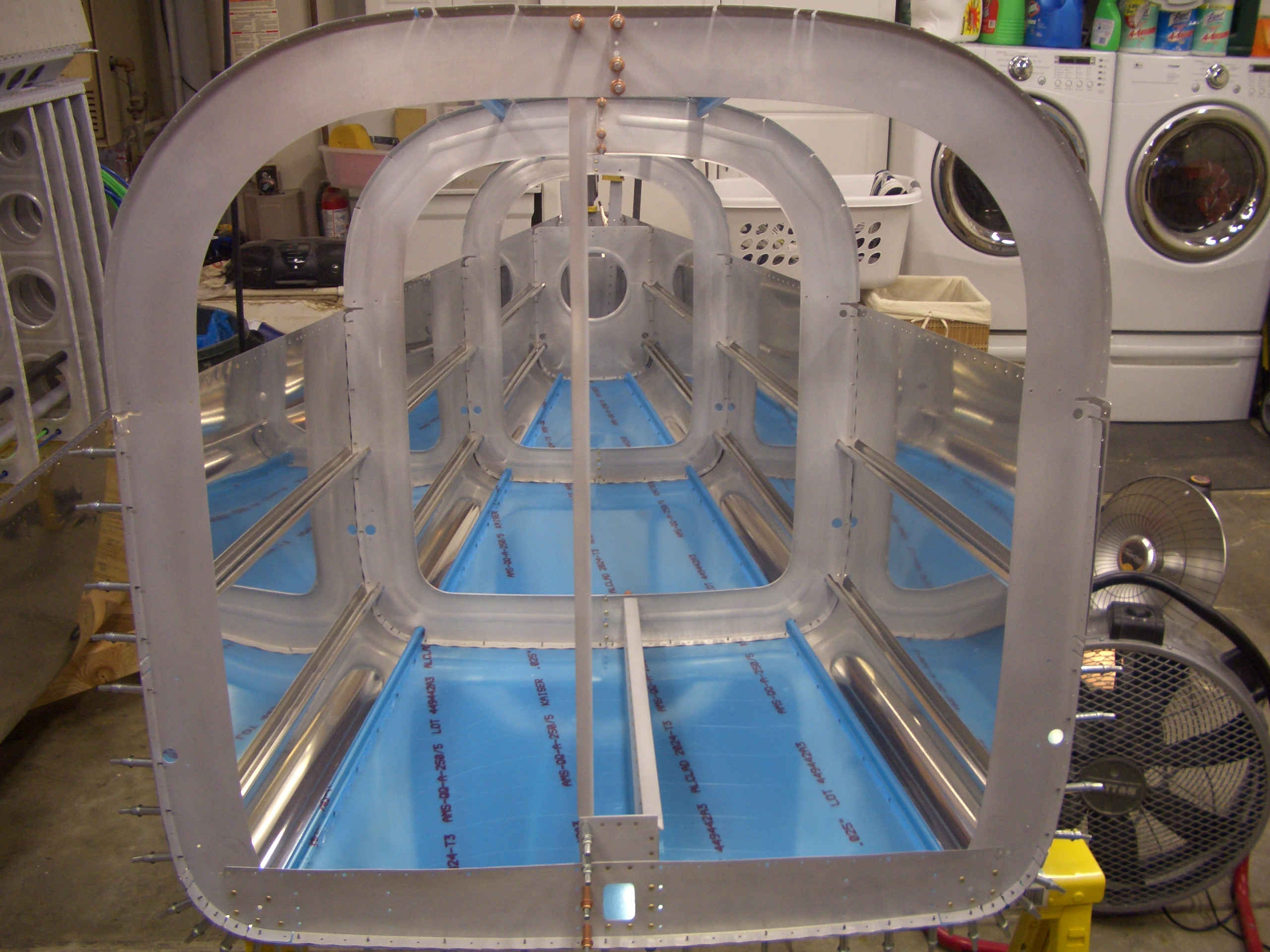
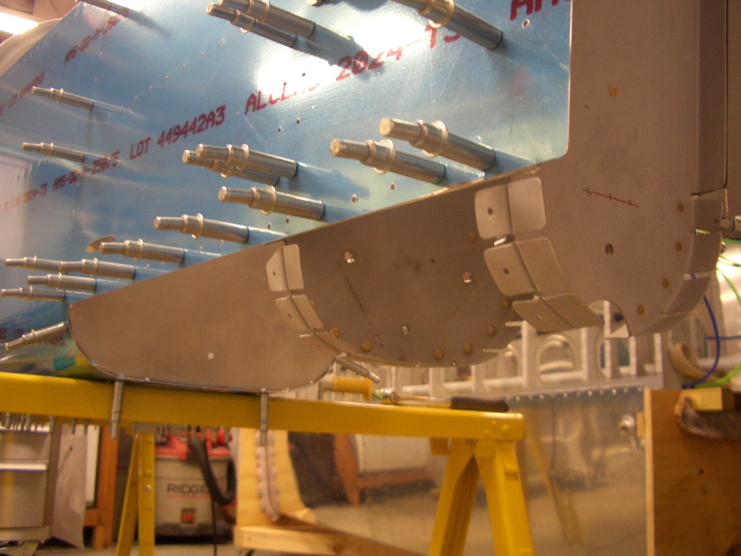
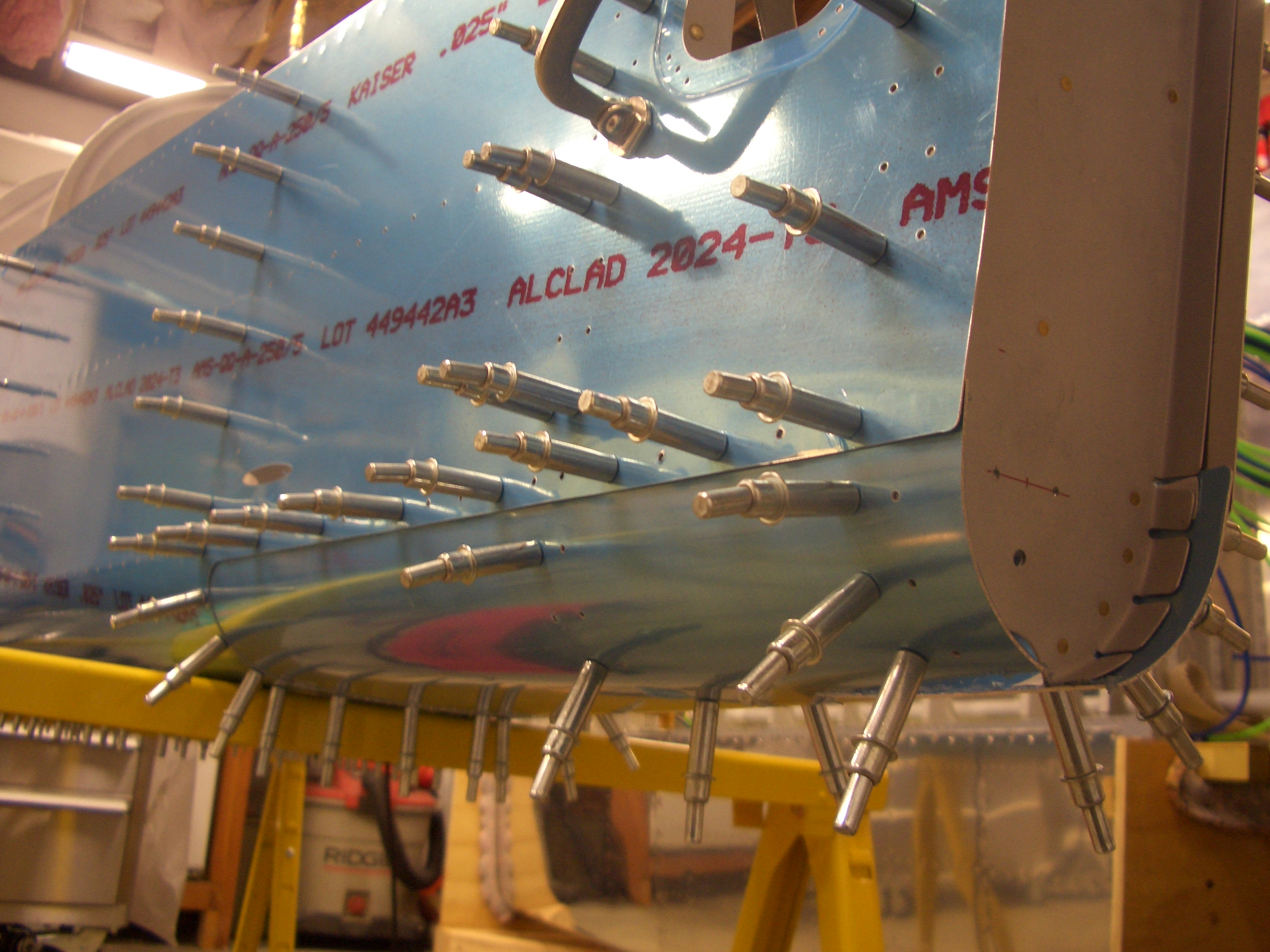
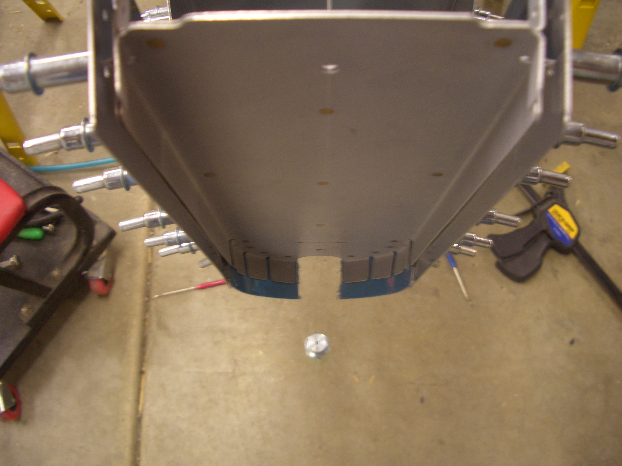
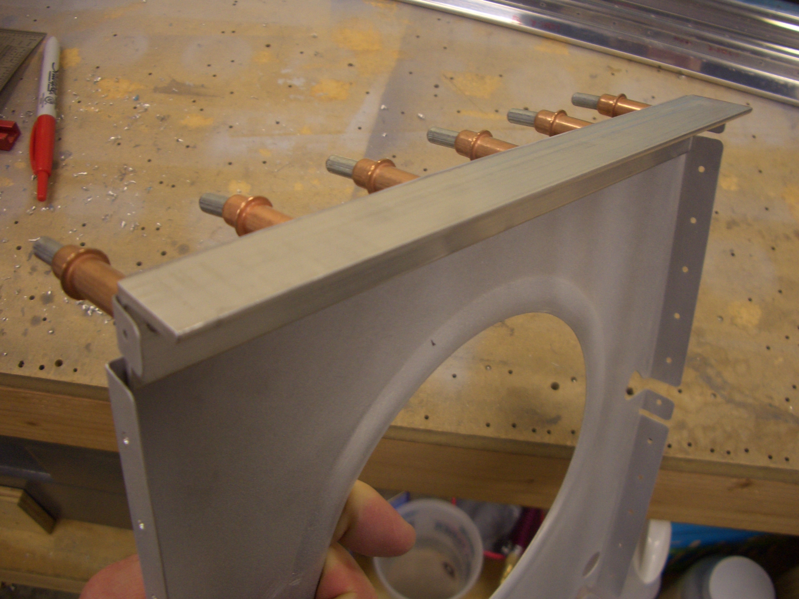
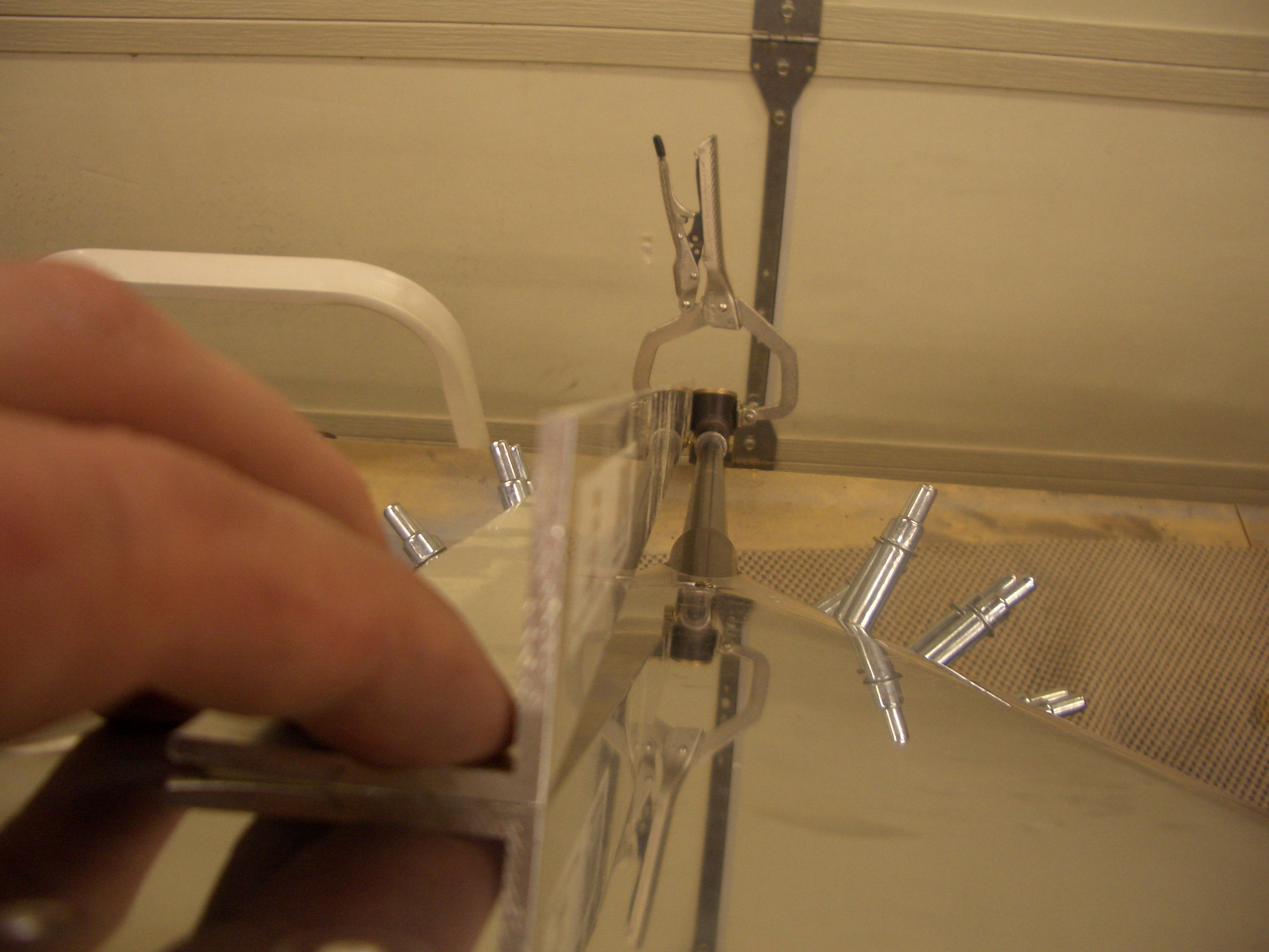
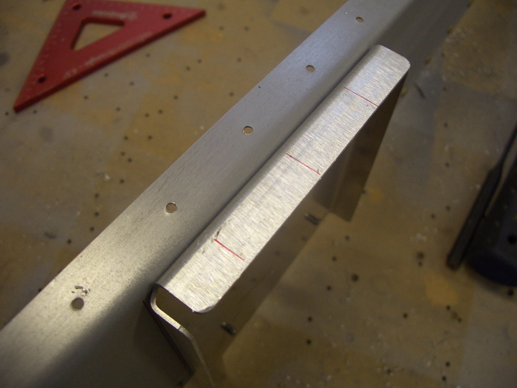
The F-710 bulkhead needs a piece of 1/8″x1″x1″ angle fabricated to sit at the top edge.  The ends have to be tapered and shaped to nest into the longerons.

The F-711 bulkhead also needs a piece of 1/8″x3/4″x3/4″ angle, also with tapered and shaped ends.  This won’t get riveted on until the side skins are riveted to the longerons.

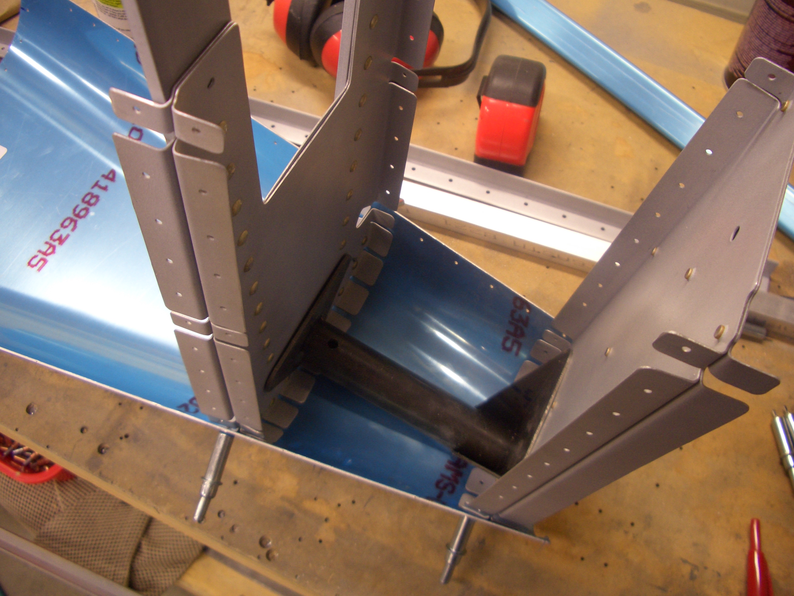
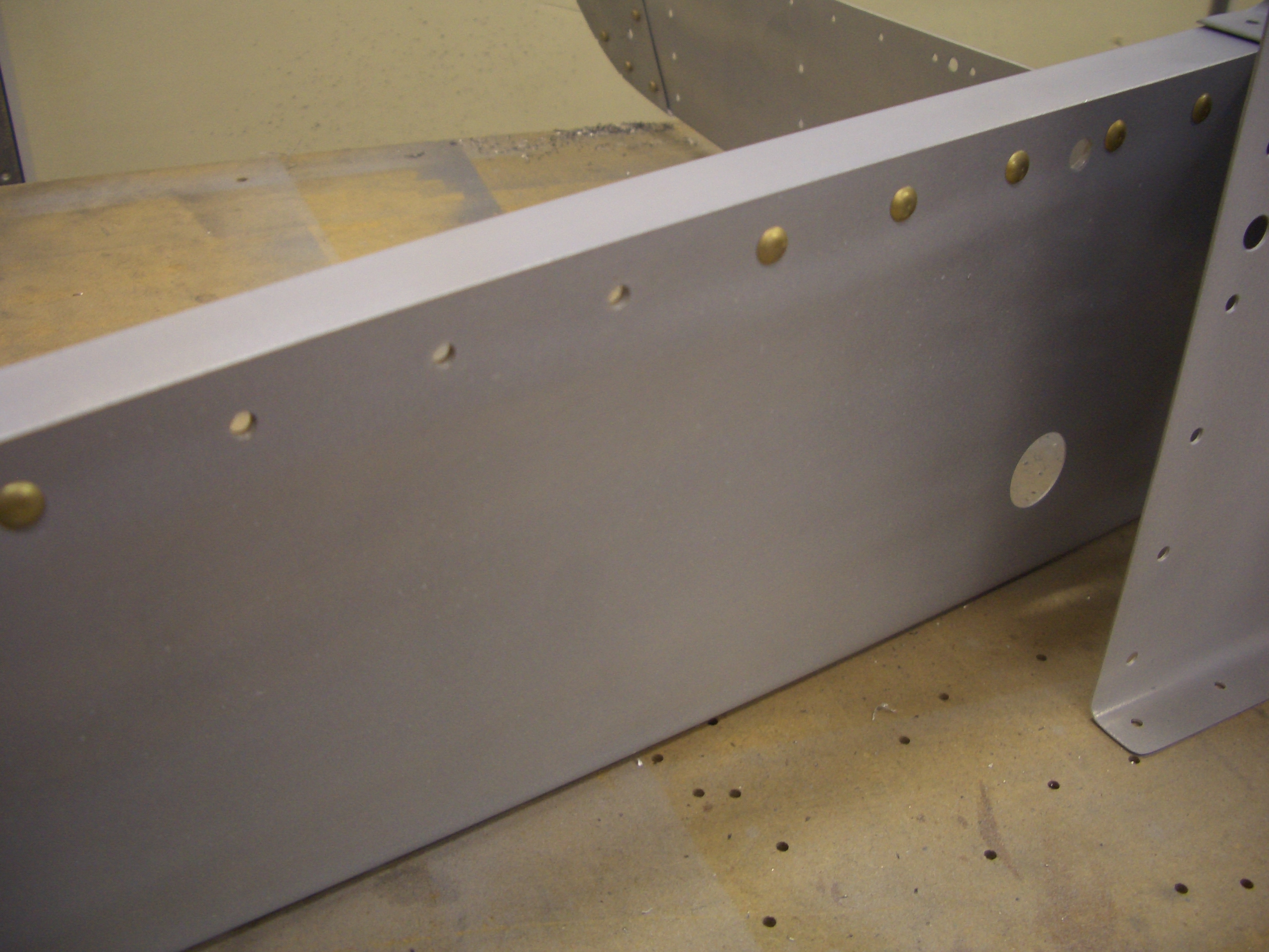
Here you can see why.  The longerons rivet to this flange on the bulkhead which is covered by the angle I just fabricated.  In fact, I had to notch the ends of the angle here to clear the future shop head for this rivet.

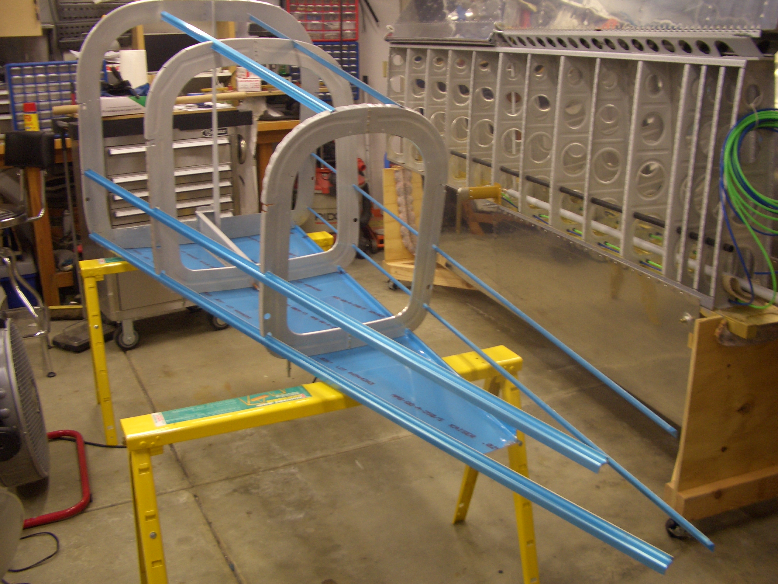
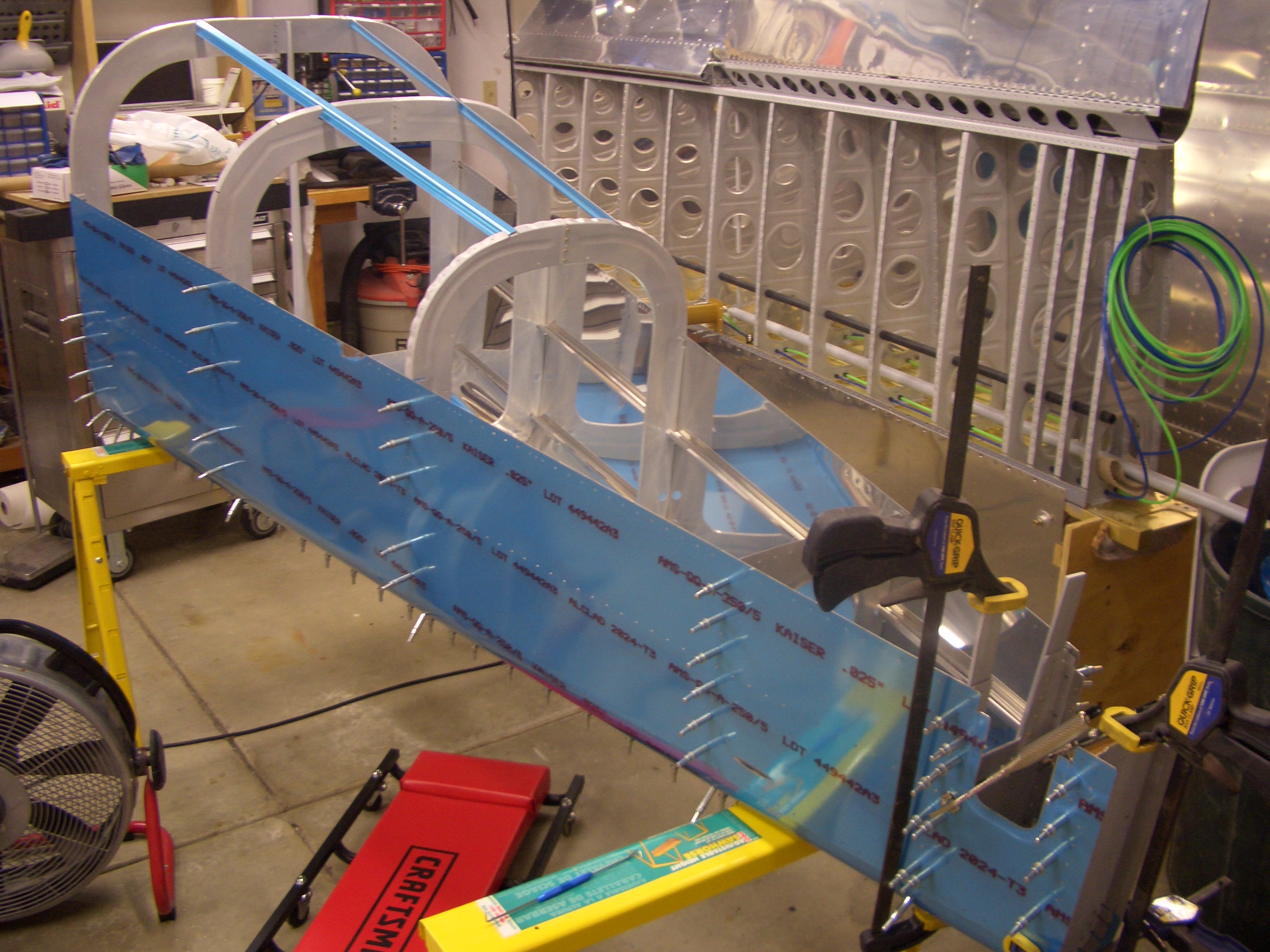
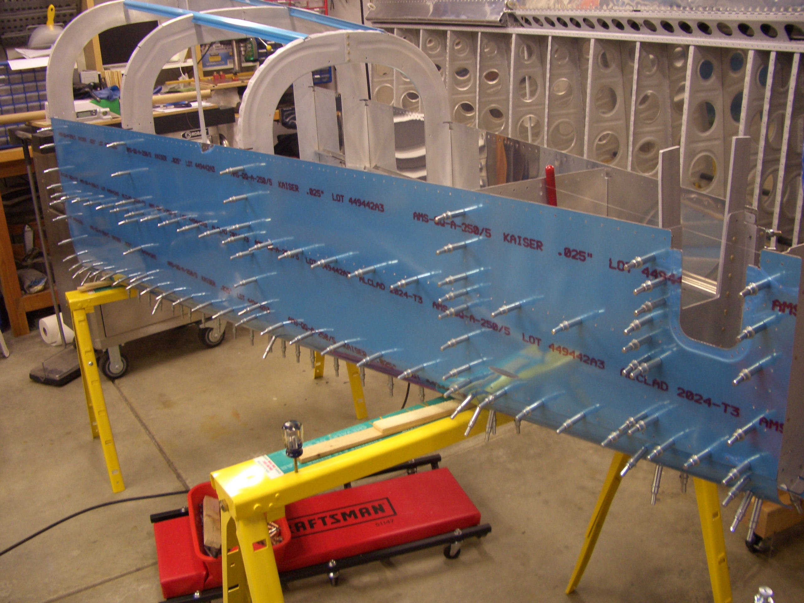
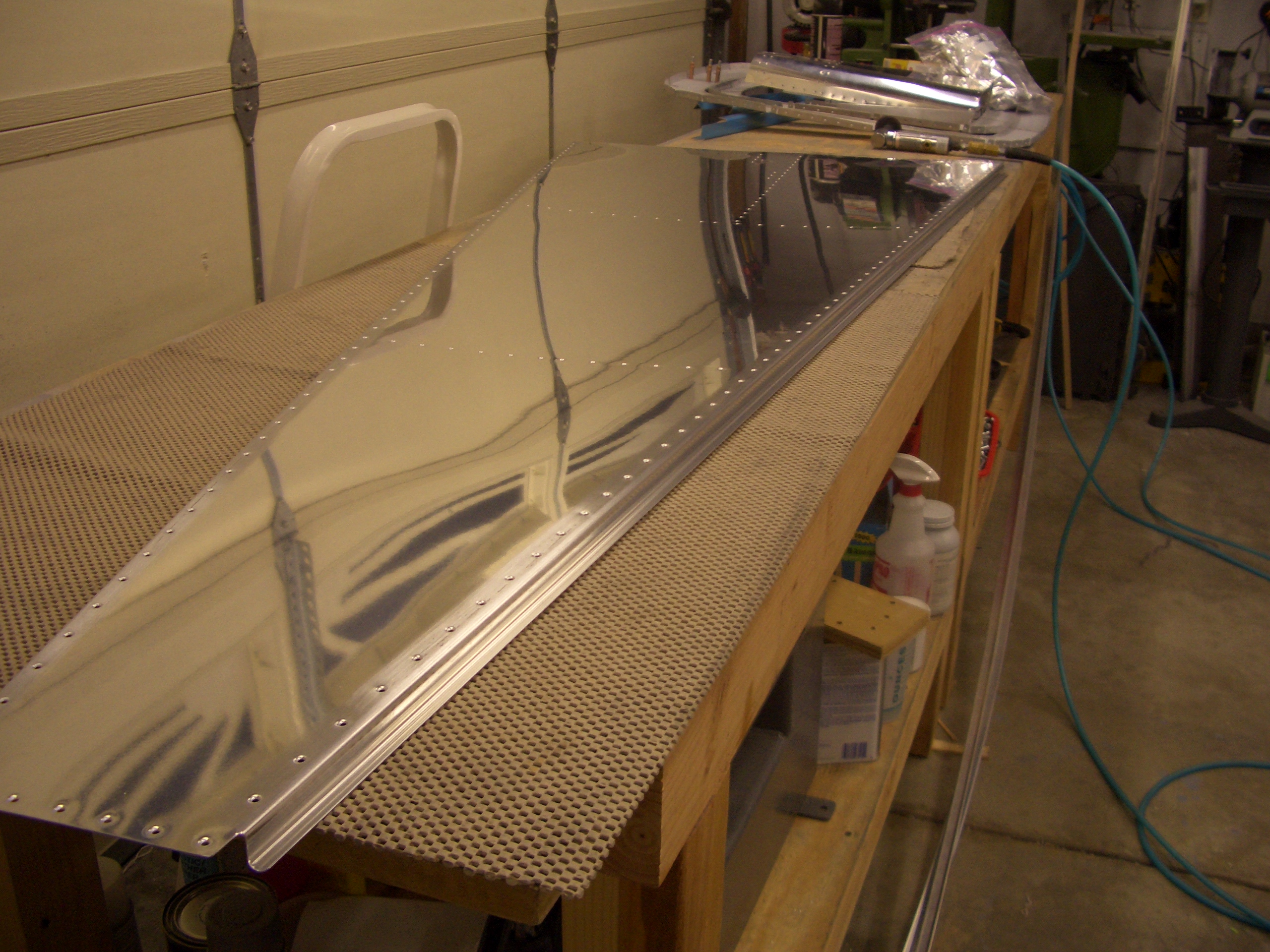
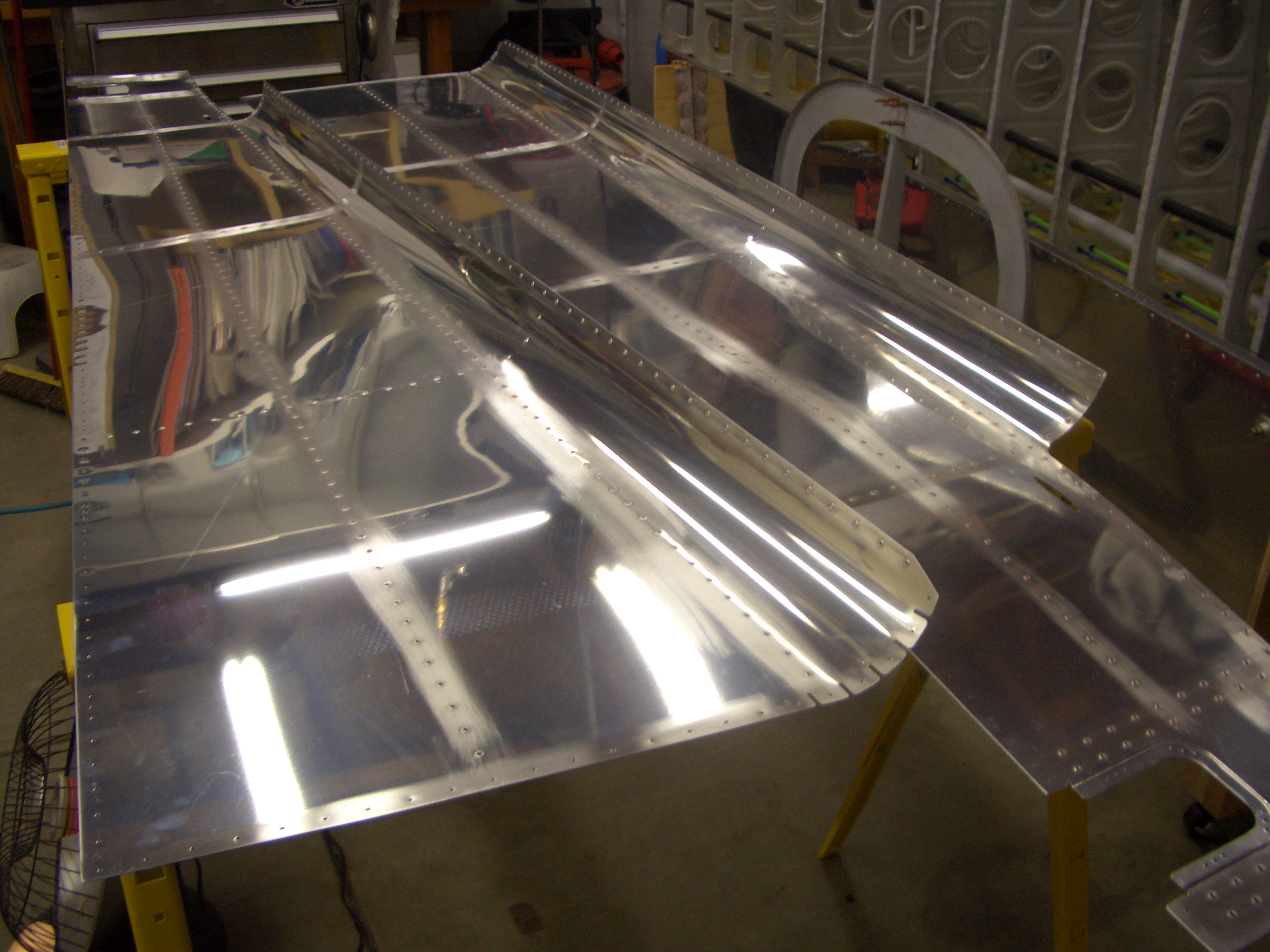
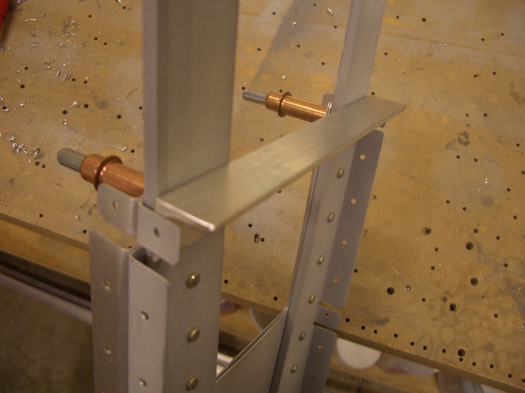
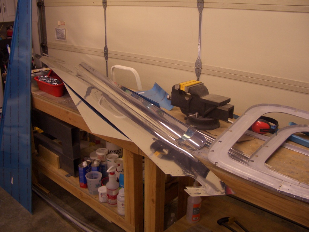
The tailcone is now fully disassembled so I can begin deburring, dimpling, and priming.

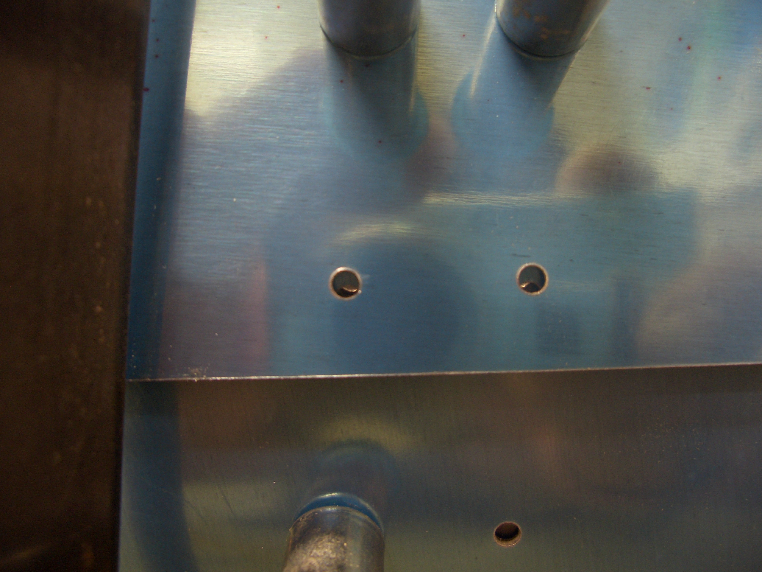
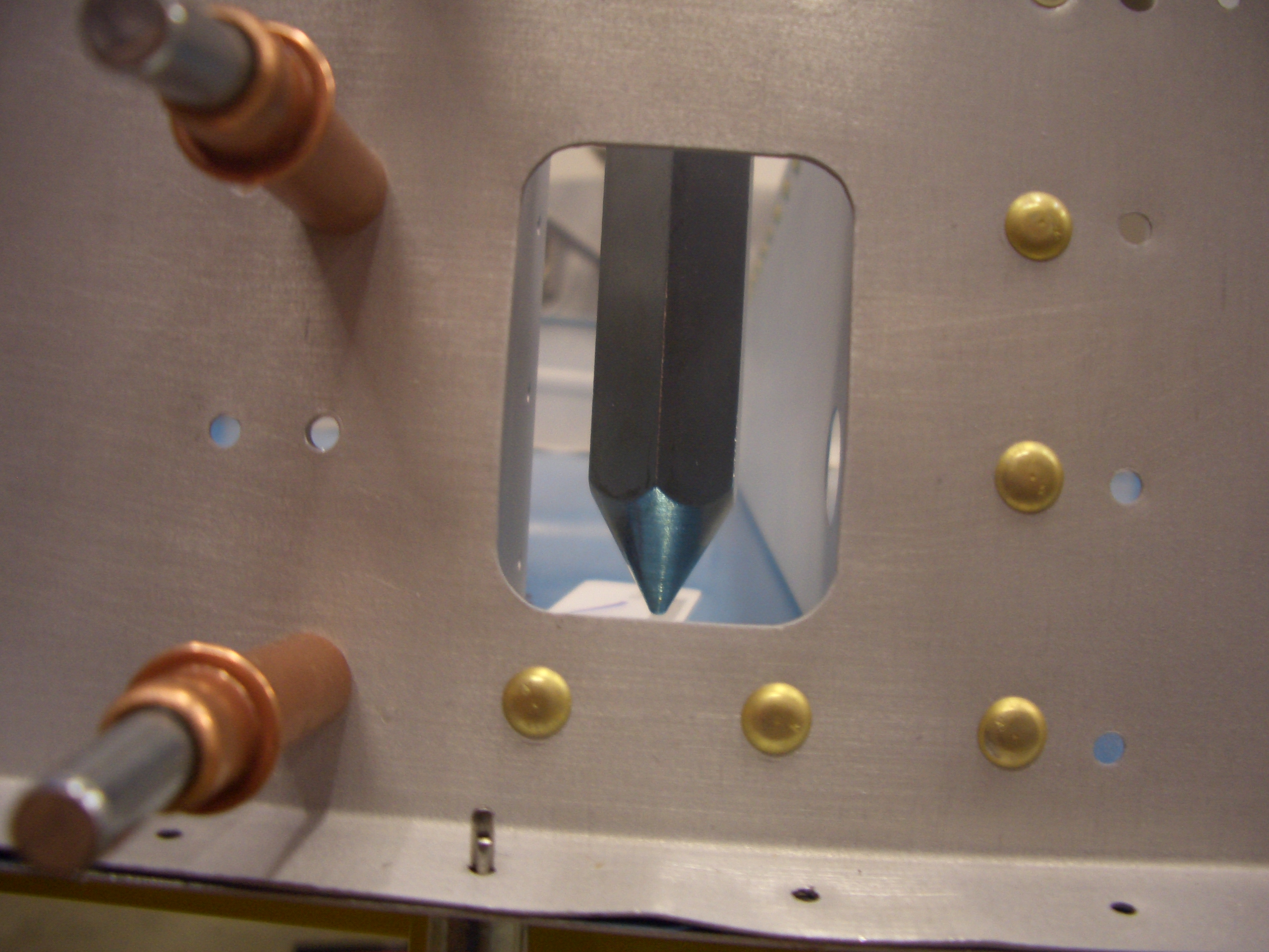
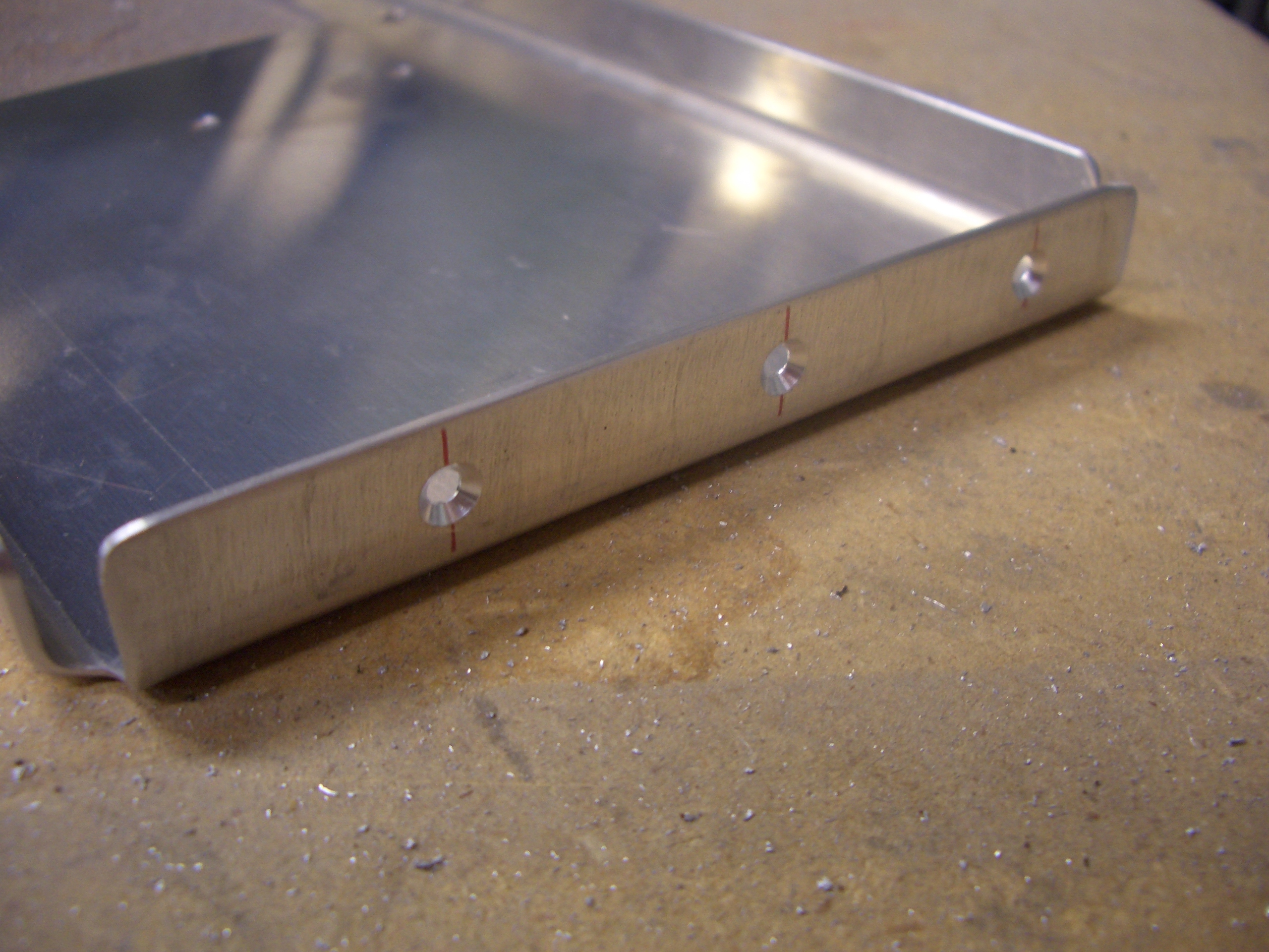
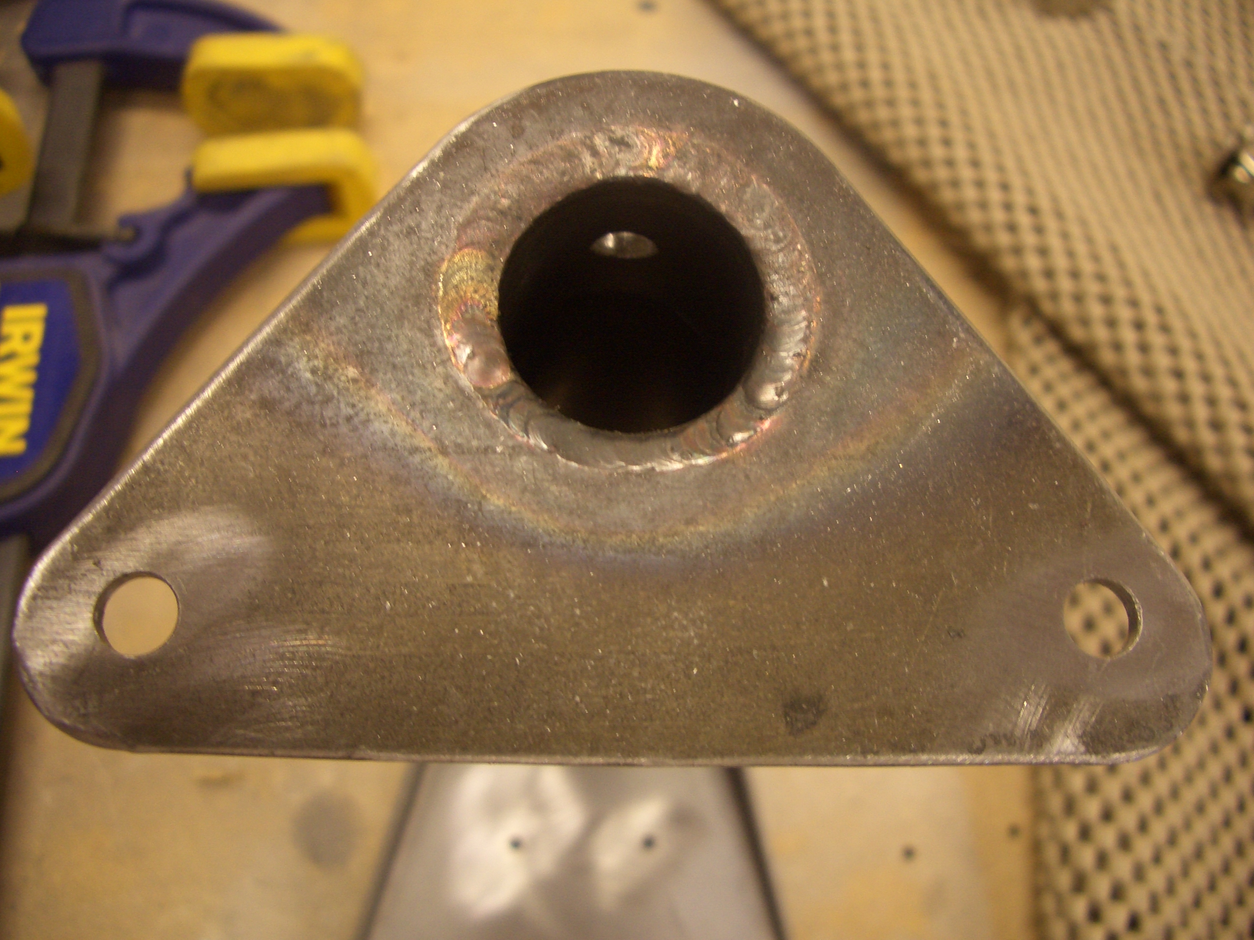
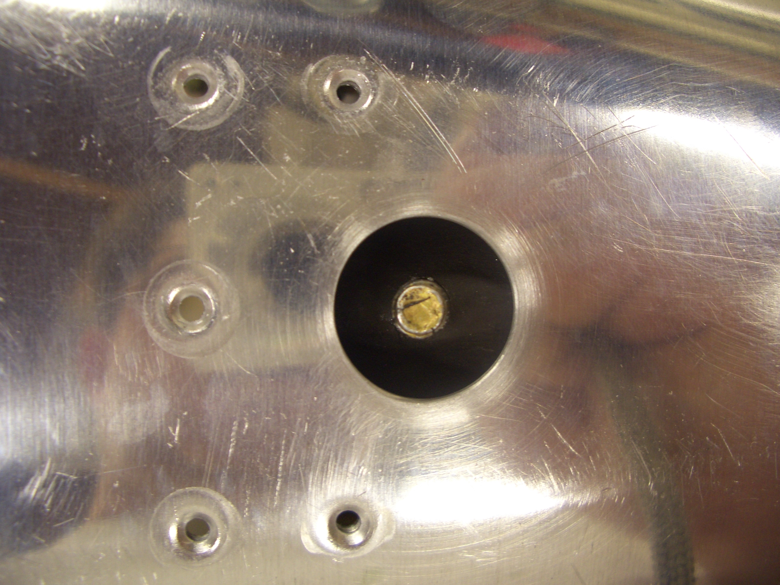
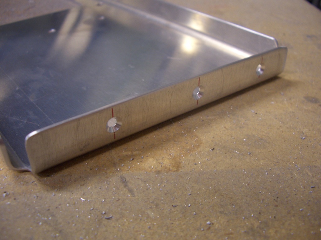
The bracket is 0.048″ thick, so it can’t be dimpled.  Instead, I machine countersunk the holes here to receive the skin dimples.

I started deburring parts, but ran out of steam.  I’d like to finish this up this weekend so I can get the tailcone riveted together before the holidays.

Prepped Tailcone for Riveting

I did a little further trimming on the mousehole so that the tail skin also cleared the welds on either side of the tail spring mount.  I haven’t decided if I’m going to paint the mount or have it powder coated yet.  I’m going to call around tomorrow and see how much it would cost to have it powder coated.

With my buddy Andre’s help, I finished prepping all of the tailcone components for priming.  It’s a bit late tonight to start the priming, but it should be fairly easy to knock it out in the next day or two.  Here is the bottom skin and all of the bulkheads behind it.

And here are the side skins.  The skins got a little scratched up inserting and removing the stringers, so I scuffed up the rivet lines and will prime those.

Drilled New Tailwheel Spring Mount

When I drilled my tailwheel spring mount, somehow one of the holes came out lower than it should (this picture is upside down, so the right hole looks too high).  Van’s confirmed the reduced edge distance wasn’t an issue, but I wanted to make sure the misplaced hole wasn’t causing the mount to be cocked to one side.  I clecoed the two rear bulkheads back to the tail skin with the mount between them and took a bunch of measurements.

Despite my best effort at positioning the mount, the tailwheel was cocked to one side about 2º.  I don’t know if that is significant enough that it would affect the handling, but it would be virtually impossible to change later, and it would bug me knowing that it’s not correct, so I ordered a new one from Van’s.  It came in today, so I wanted to get it drilled to the fuselage tonight.

Unfortunately, the new mount didn’t have the hole drilled in it that attaches the mount to the spring (the one under the drill bit).  I needed to figure out how to drill a hole in the mount that would somehow line up with the hole in the spring inside.  What I ended up doing was positioning my v-block so that the hole would be the right distance from the right end when the flange was butted up against the v-block.  I then took a reading with my digital level of the angle of the flange top edge when the drill bit was pushed all the way through the old mount.  I then positioned the new mount so the flange top edge was at the same angle and clamped it down.  I drilled through the top wall of the tube and then put the spring in place and lined up the holes.  I then used that as a guide to drill the bottom wall of the tube.  This resulted in perfect alignment of the holes.

I then used some scrap 1/8″ angle to make sure the tailwheel fork tube was exactly perpendicular to the tail skin.  This picture shows how the angle is clamped to the tailwheel fork tube and rests on the tail skin.

And here you can see that this is perfectly perpendicular.  I clamped the angle to both sides of the tailwheel fork tube to make sure the measurements agreed.

This shows that the tailspring bolt is perfectly centered in the hole in the tail skin (with the old mount, the bolt was cocked noticeably to one side).  After everything was clamped in place, I drilled the mount to the F-711 and F-712 bulkheads.  I double checked that the tailwheel fork tube was straight, and it was perfect (easily within 0.1º of vertical); I feel much better now.