Aileron Skins and Spars

I went out before work this morning and backriveted all of the stiffeners on both of the aileron skins.

Using the bending brake I made for the empennage skins, I bent the aileron skins.  I ended up having to fine tune the bends with the hand seamer.  Just like on the elevators, you want the skin to stay perfectly straight from the spar back to the trailing edge radius.

The ends of the aileron spars need reinforcing plates where the hinge brackets attach.  These are made from 0.040″ aluminum and match drilled to the spars.

After match drilling, the hinge brackets are clecoed on…

…and drilled out with a #12 drill for AN3 bolts.

Before calling it a night, I also clecoed the leading edge ribs in place and match drilled them to the skin.

Drilled Left Aileron

I clecoed the left aileron completely together in preparation for match drilling.

The aileron counterweight is a galvanized iron pipe that runs the whole length of the aileron.  This has to be drilled to #30 for countersunk blind rivets.

The entire bottom of the spar (with the exception of the outboard two rivets) also has to be drilled to #30 for blind rivets because there is no way to reach inside and buck these.

There is also a hole that attaches the counterweight pipe to the nose ribs so that the pipe can’t rotate.  This can be reached through one of the #30 holes in the spar after the trailing edge skin has been removed.

Drilled Right Aileron

No pictures tonight as they would be indistinguishable from yesterday’s.  Basically, I repeated all of yesterday’s steps on the right aileron, but I did it quite a bit quicker tonight since I didn’t need to refer to the instructions.  Afterward, I got started deburring some of the components.  Van’s instructions have you prime at several points along the construction.  Instead, other than the stiffeners, I’m waiting until all of the aileron components are ready to prime at the same time.

Worked on Ailerons

My Dynon autopilot roll servo showed up today.  I’m not going to install it just yet because I’m waiting on an order from B&C for some d-sub 9 connectors so I can fabricate a connector for this at the servo.

I countersunk the galvanized pipe used as the aileron counterweight.

To form the dimples in the skin, I mounted the 1/8″ male die on a special bucking bar I bought.  Using the galvanized pipe as the female die, I hammered this into the holes in the skin.

…resulting in dimples in the leading edge for the CS4-4 blind rivets.

Preparing to Rivet Wing Leading Edges and Top Skins

I put together a punch list of things to do before riveting the wing leading edges and top skins.  I made it through most of the list today before running out of steam.  My buddy Andre is coming over tomorrow morning to help with the riveting, so I want to be ready to hit the ground running.  Unfortunately, the 4×4 posts on my wing jig twisted and pulled the brackets out of alignment.  I had to take both wing skeletons down, redo the brackets, and re-level and straighten the spar.  That took most of the time today.

Here are the outboard leading edges clecoed on for the last time.

Fabricated Autopilot Roll Servo Wiring Harness

My order from B&C Specialty arrived yesterday with the wiring components I need to fabricate the connection between the autopilot roll servo and the wiring harness.  First up is to crimp the sockets onto the wires on the wiring harness.  It’s hard to tell from this picture, but these wires are small.  The wires are a mix of 20 and 22 gauge, and these sockets are about 1/16″ in diameter.

Next up is to crimp the corresponding pins onto the wires on the roll servo.  Afterward, I put these wires in some heat shrink tubing to keep them tidy.

Here are the wires from the servo inserted into the D-Sub 9 pin male connector body.  The goopy stuff on the wires in E6000 adhesive.  Basically, this forms a strain relief that prevents individual wires from flexing at the connector.

Here is the corresponding female connector on the wiring harness.

Riveted Left Wing Leading Edge and Top Wing Skins

I got started this morning by forming the scarf joint where the inboard and outboard top wing skins meet just behind the tank skin.  This keeps the skins from sticking up where they are doubled up.

Andre stopped by and we got started by riveting the leading edges onto the spars.  This required the double offset rivet set I modified the other day.  Bucking these was tricky since it required reaching way into the leading edges through the lightening holes and bucking blind.  We managed to get all solid rivets into these holes.

Here’s a shot inside the leading edge showing the shop heads for some of these rivets.

Afterward, we squeezed the rivets along the spar.

We then clecoed the wing skins on (remembering the wing-walk doublers of course).

We back-riveted all of the skins on using a 5 lb back-rivet bucking bar.  This was held against the outside of the skins while…

…the rivets were driven from the inside using an extended reach double-offset back-rivet set.  This worked beautifully.  The outside of the skins look perfect and we didn’t have to reach between the ribs to hold the bucking bar as we would for normal shooting/bucking (which is painful between the wing walk ribs.

After squeezing the rivets on the rear spar, the left wing is ready to come off the wing jig.

Here is the top of the wing from the outboard end.

Here is the bottom of the wing.  The bottom main skins (inboard and outboard) are riveted after everything else in the wings are complete (ailerons, flaps, control linkage, pitot tube, autopilot servo, etc.).

Pitot Mount Fitting

I didn’t have much time to work on the plane tonight, but I decided to start modifying the left bottom wing skin for the pitot mount.  I’m using the pitot mount from SafeAir.  The mounting instructions call for mounting the pitot tube in the bay just outboard from the last access hole.  The problem with that is that it also puts the pitot tube just outboard of the tie-down bracket.  Since RVs have relatively narrow wing spans compared to typical GA aircraft, it means that tie-down ropes typically splay outward from the tie-down brackets.  This means they could easily get caught up in the pitot tube and damage it.  Instead, I’m mounting the pitot tube in the bay just inboard of the last access hole.  This is only about 1′ inboard from the recommended mounting location, and only about 3″ inboard from Van’s stock location, so it shouldn’t have any impact on pitot measurement (others who have mounted it here confirm that it works great).

Since I’m mounting the pitot tube just behind the tank, the tank attach platenuts prevent the mounting bracket from sitting as far forward as the installation instructions call for (I have to mount it about 1/4″ aft of the recommended location).  Since I’m deviating from the instructions so significantly, I decided to just scrap them and improvise.

I took some measurements off of the leading edge and the adjacent rib holes.  While ensuring the tube will be aligned with the airflow, I marked where the cutout goes.  It’s late, so I’ll cut this later.

Pitot Tube and Mount

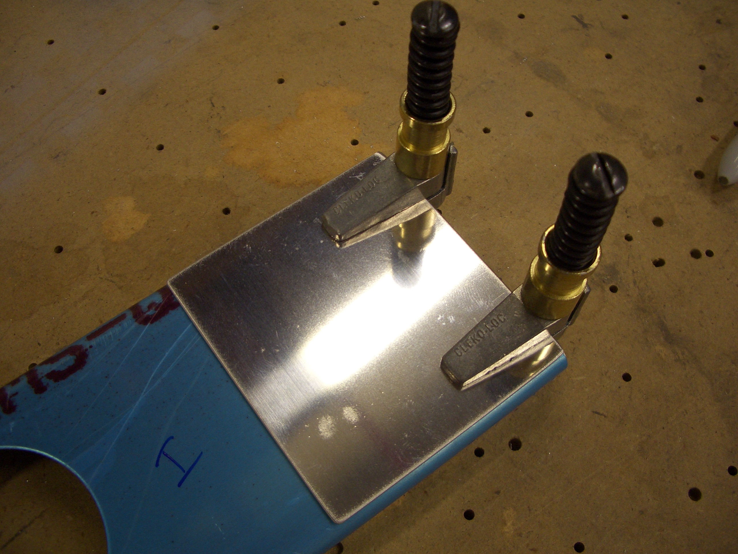
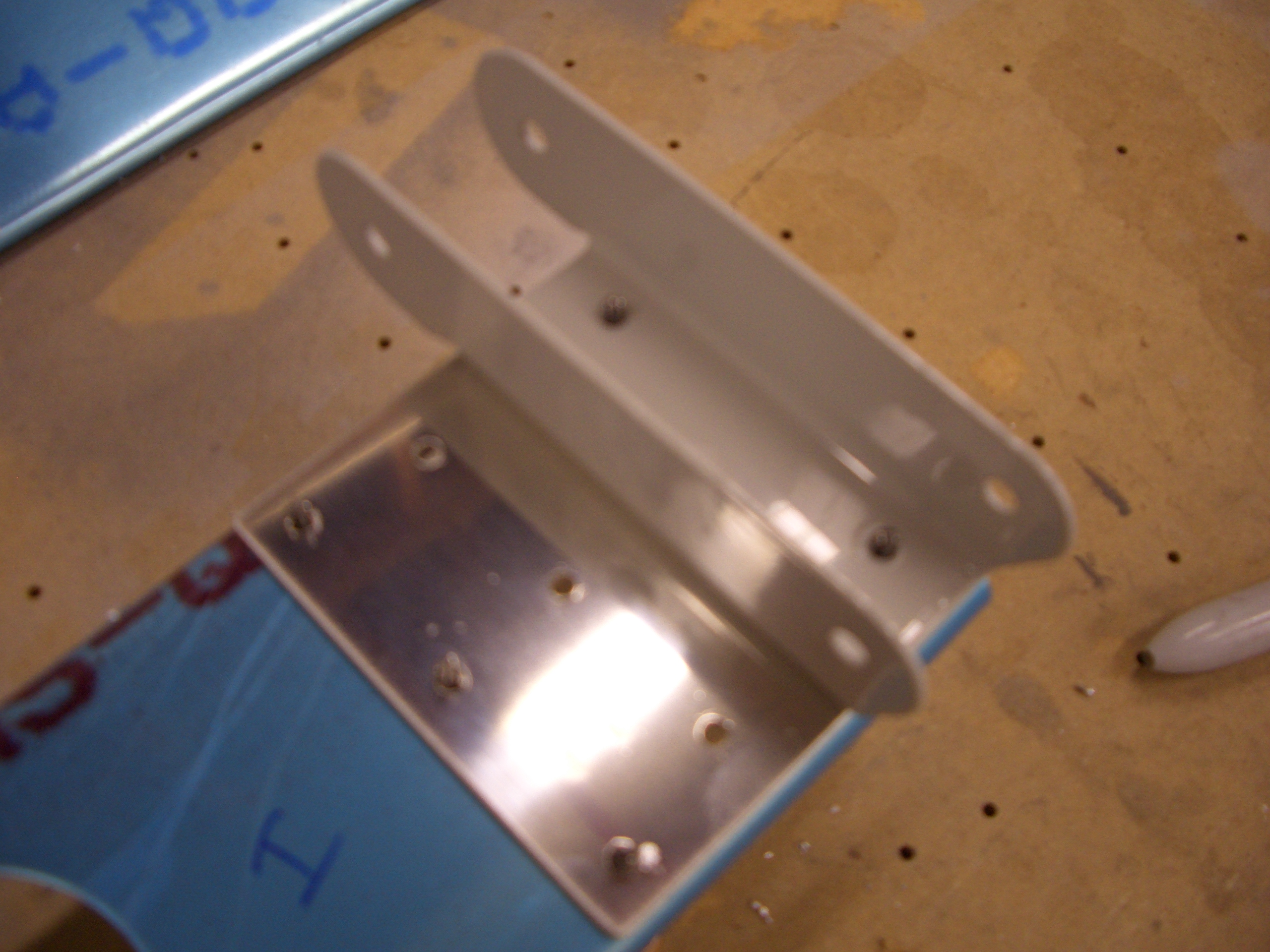
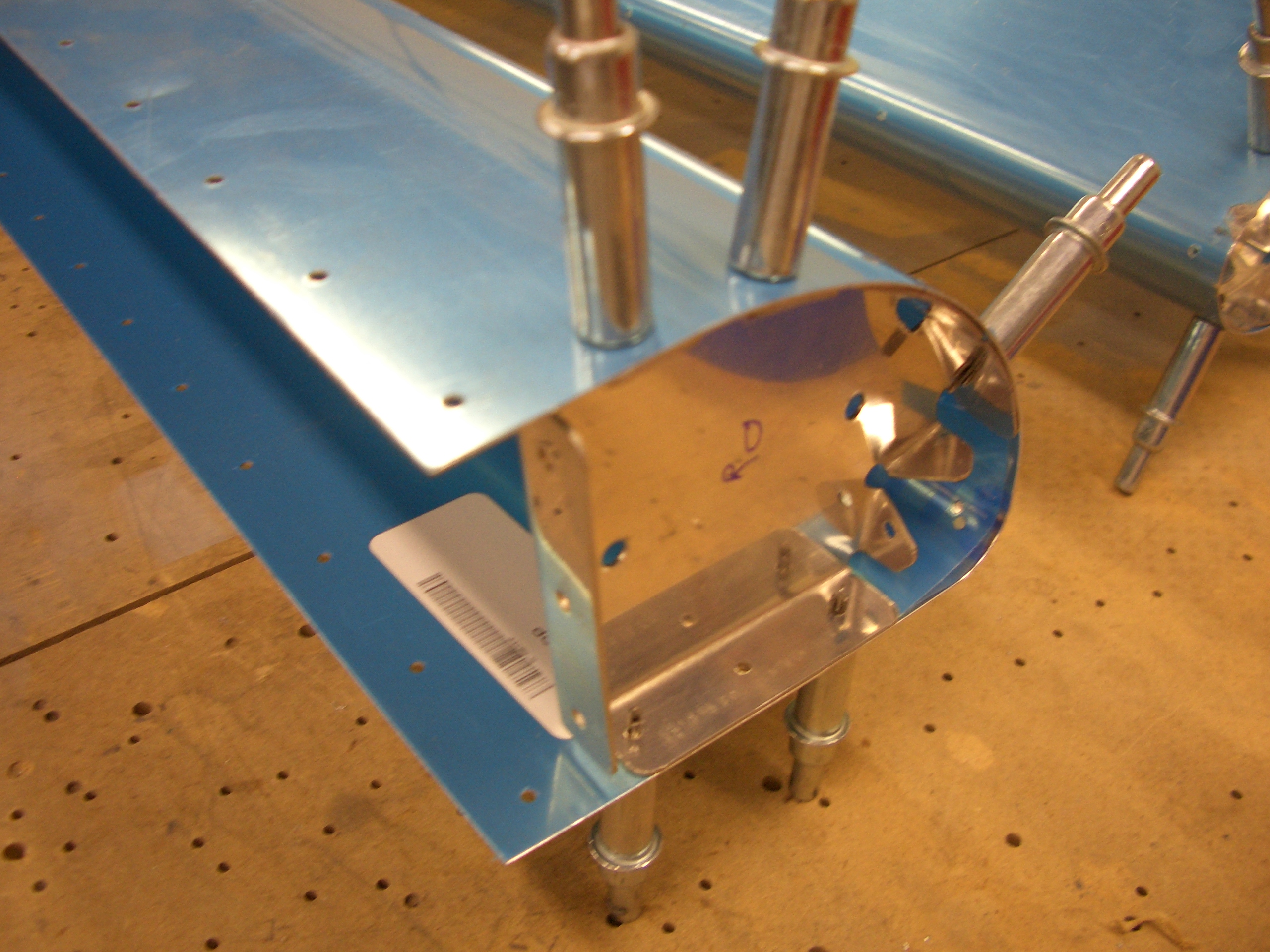
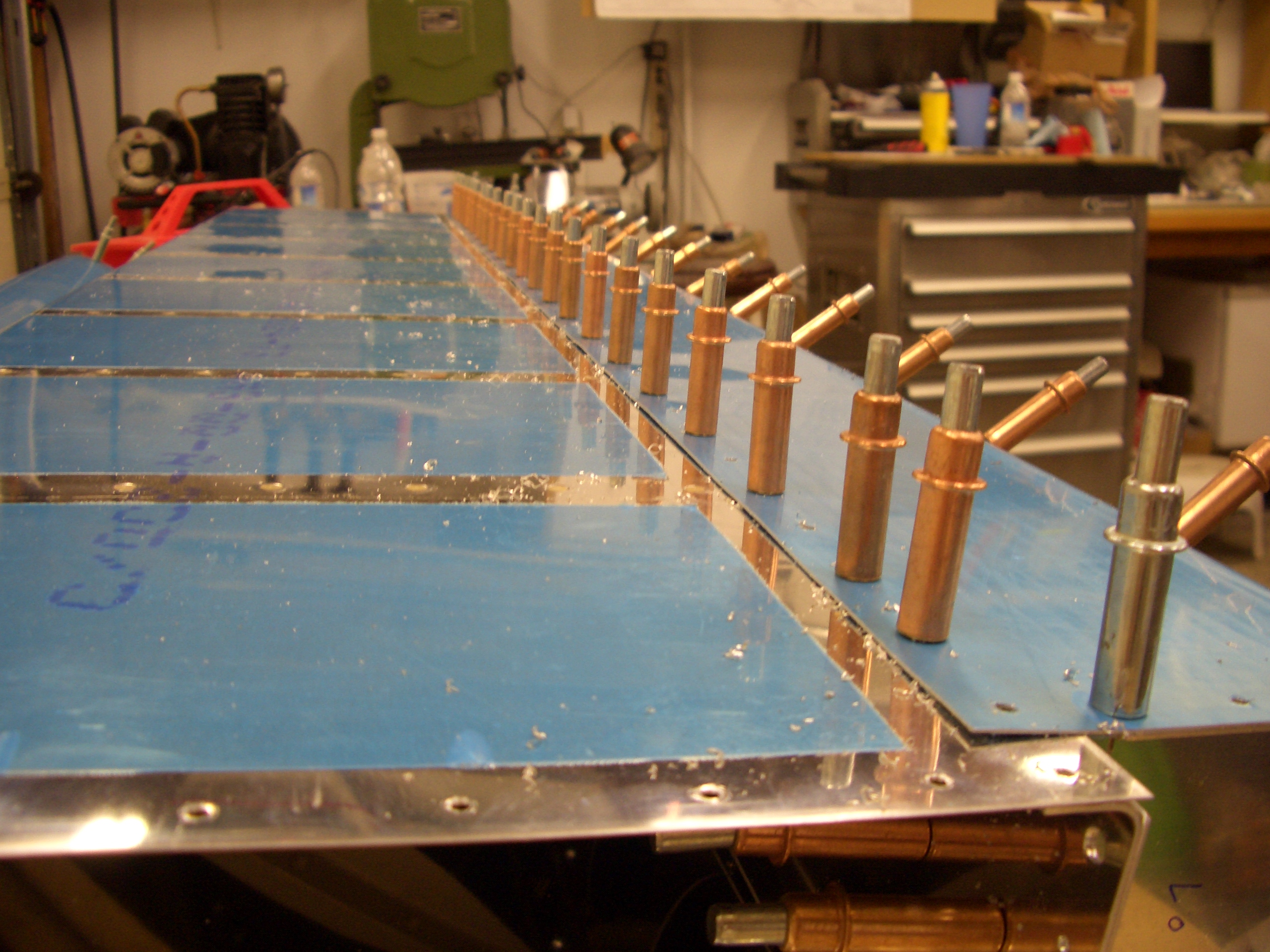
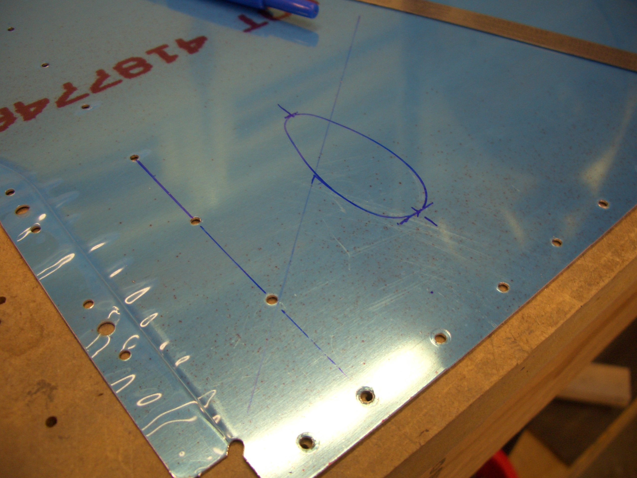
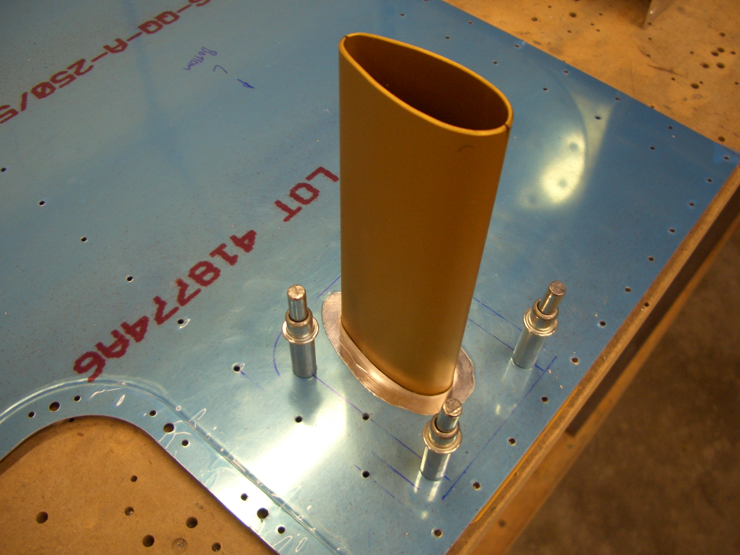
I got started tonight by cutting out the hole for the pitot mount that I laid out a couple of days ago.  I used a unibit to drill out the bulk of the material, then used a nibbler and files to finish off the hole.  Next, I laid out some holes to rivet the mount to the skin (in addition to the holes along the right edge where it will rivet to the spar).

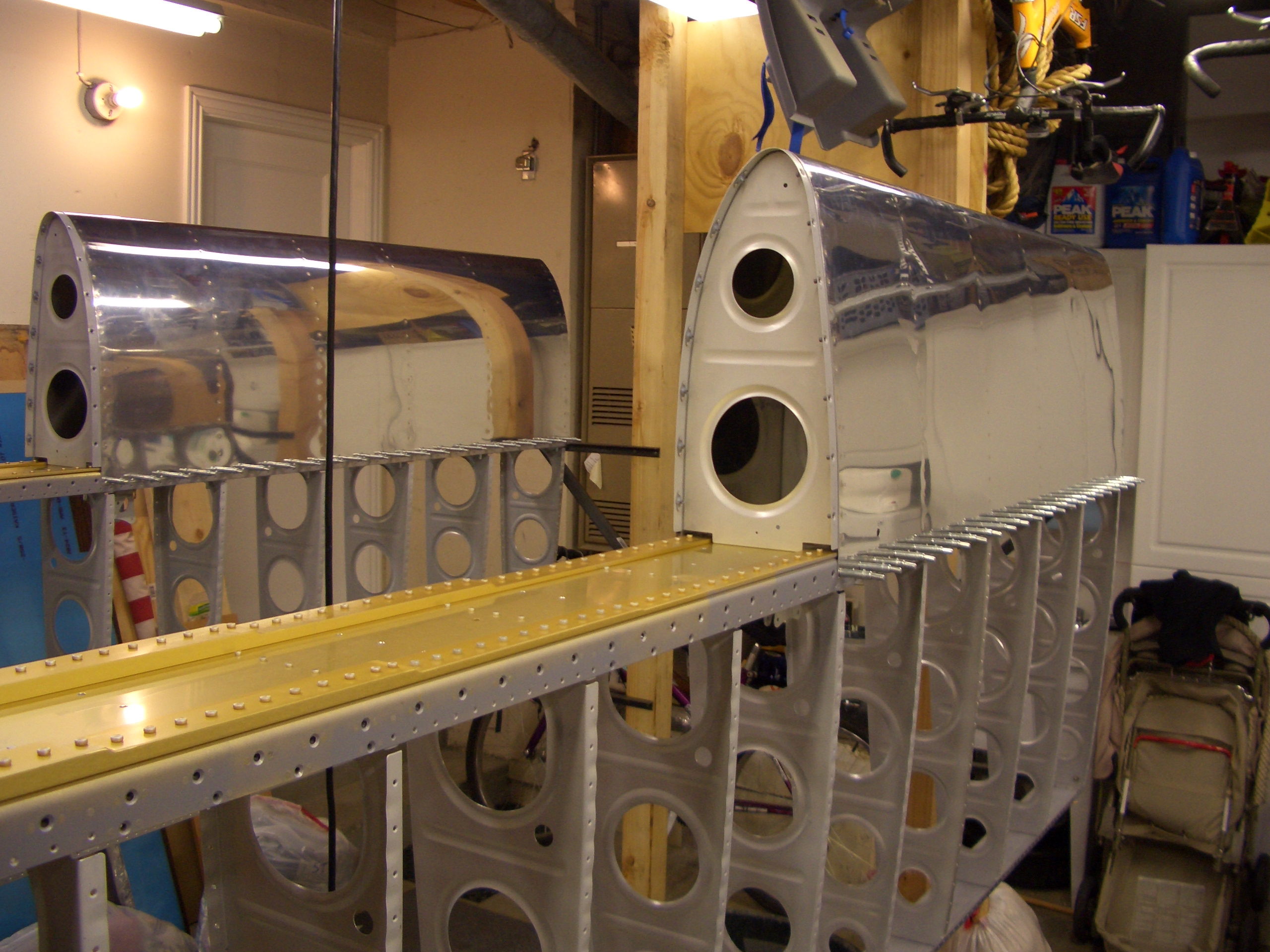
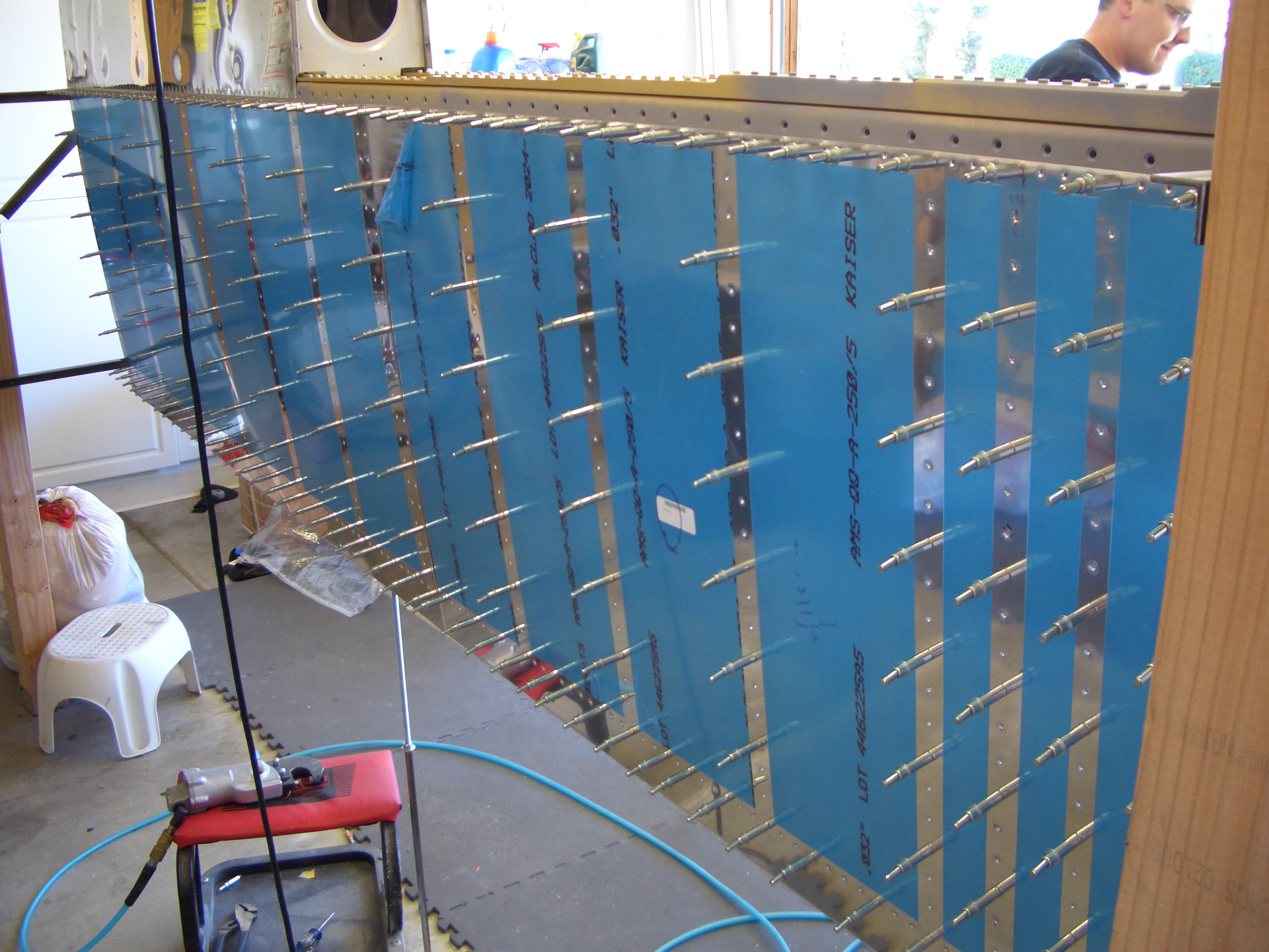
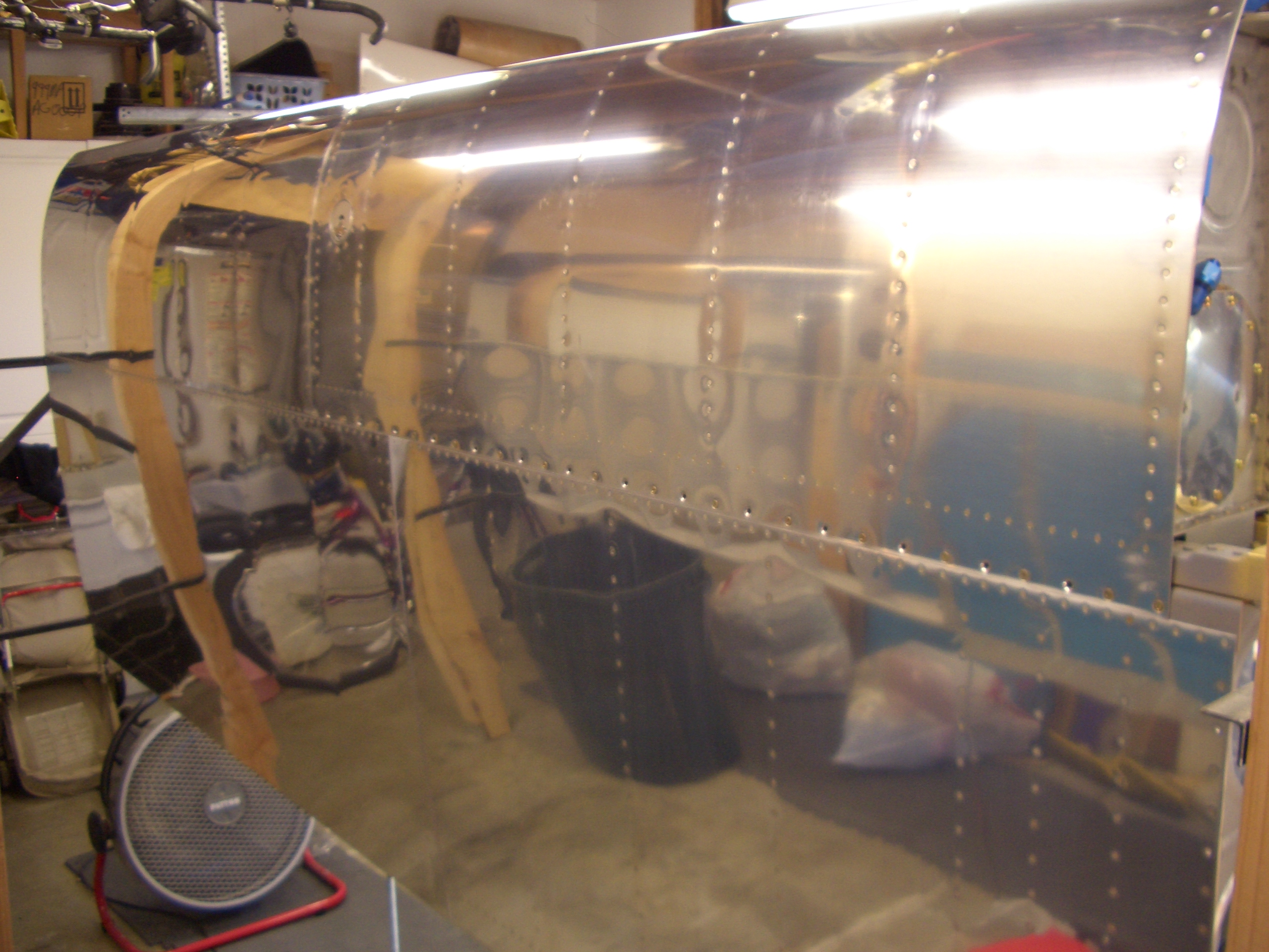
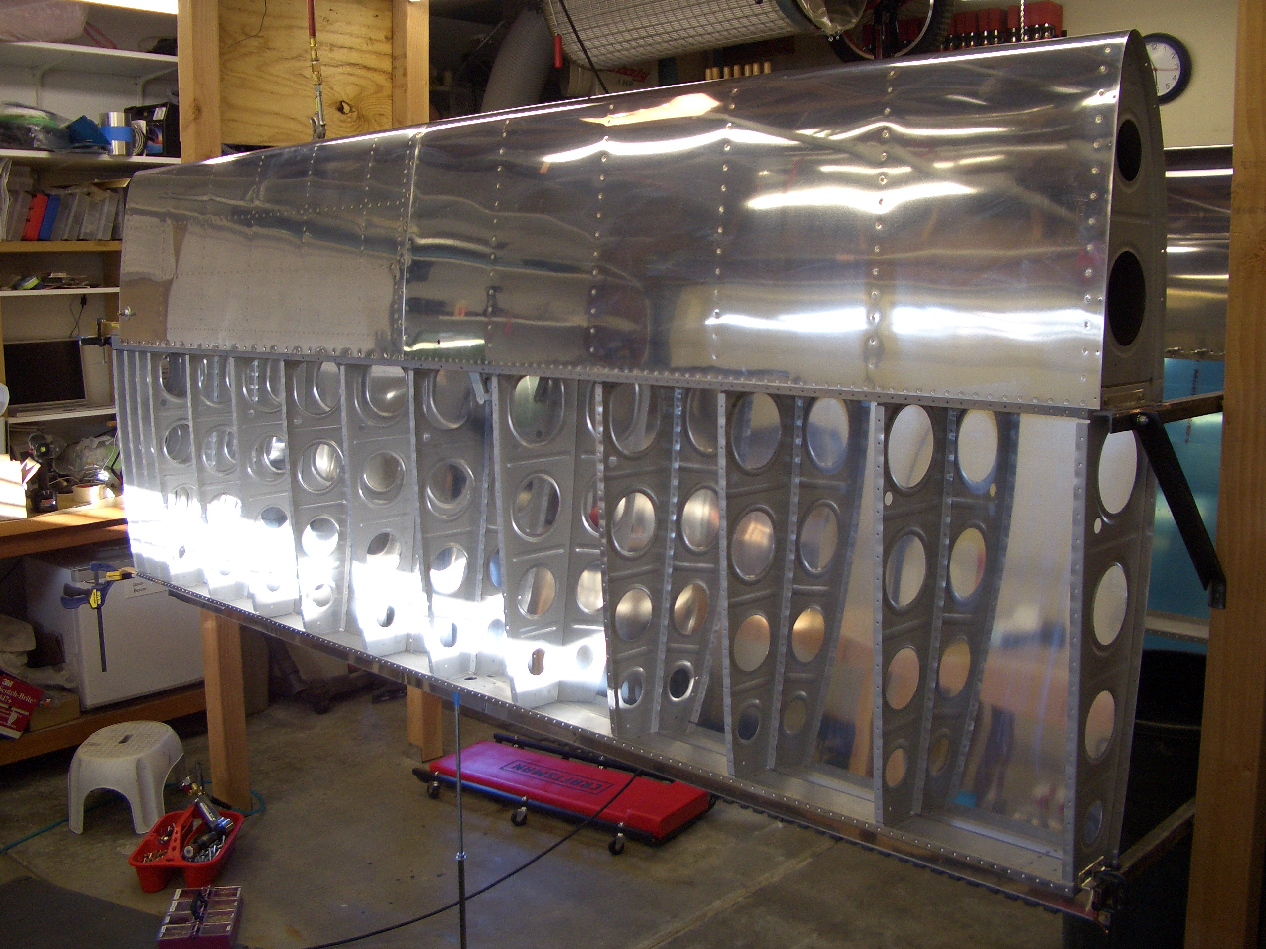
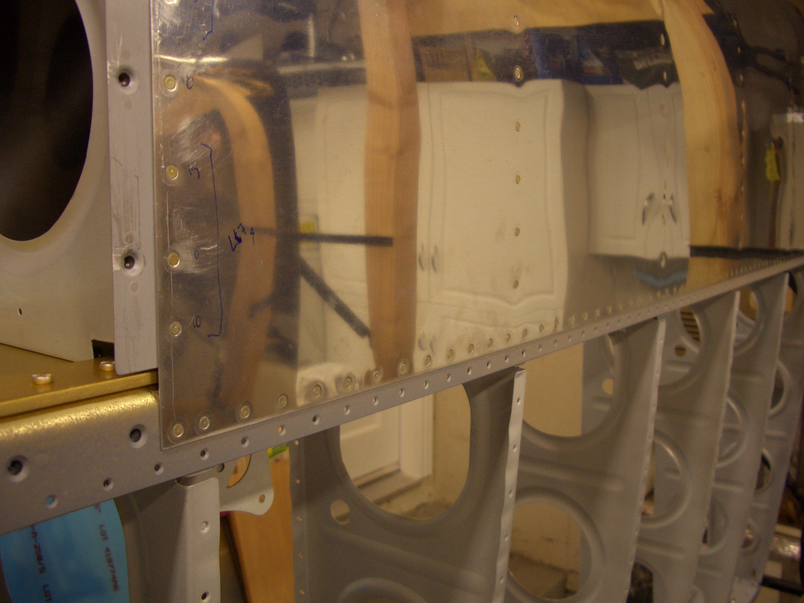
I installed the skin on the wing and match drilled the mount to the spar.

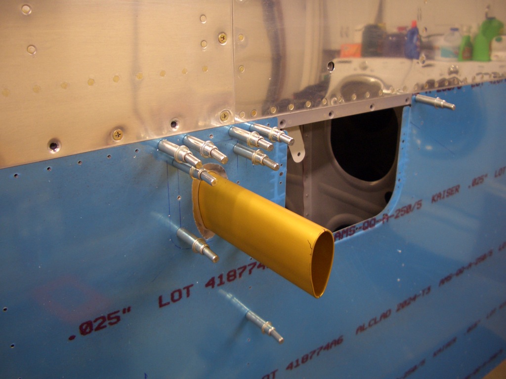
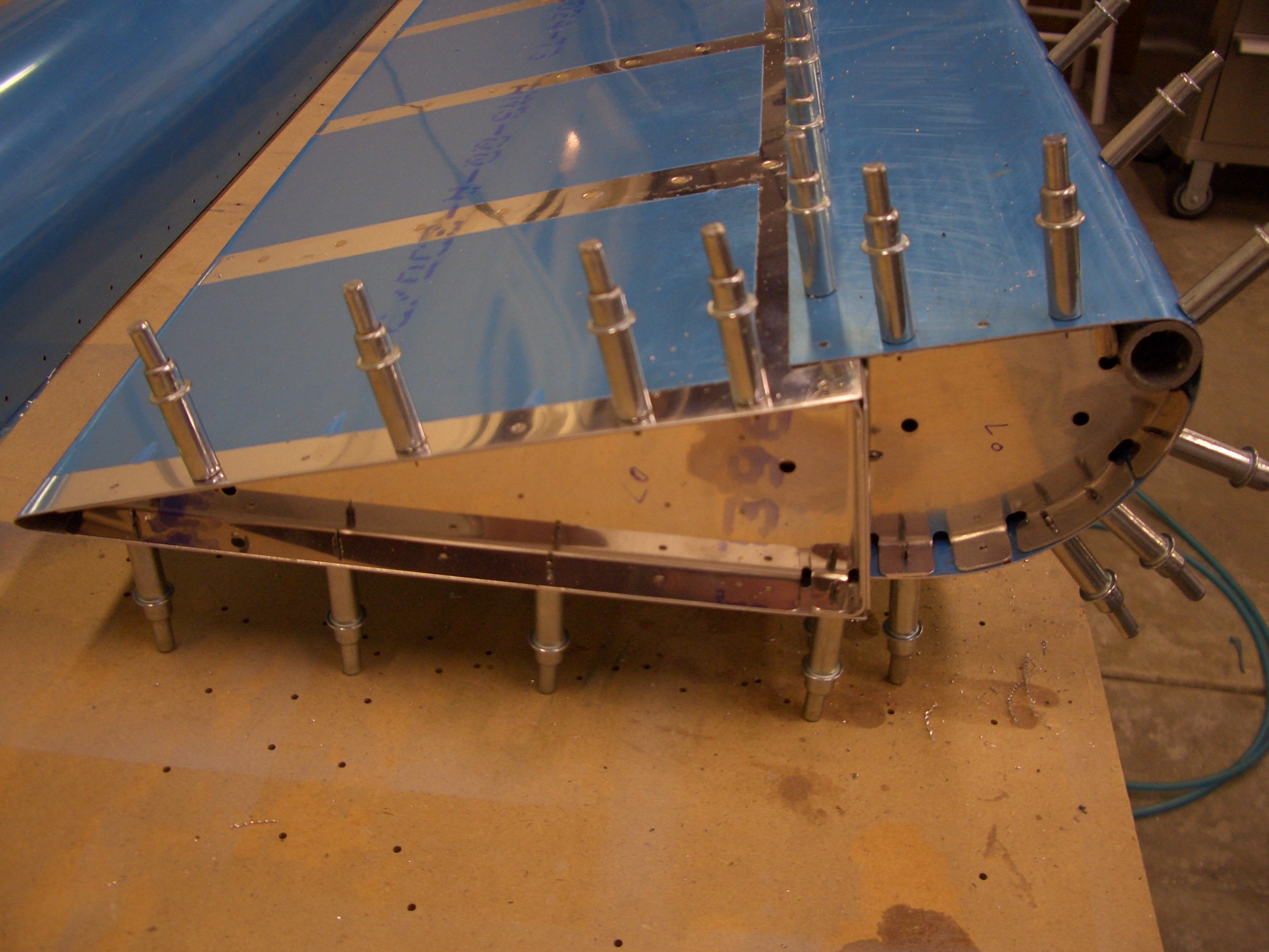
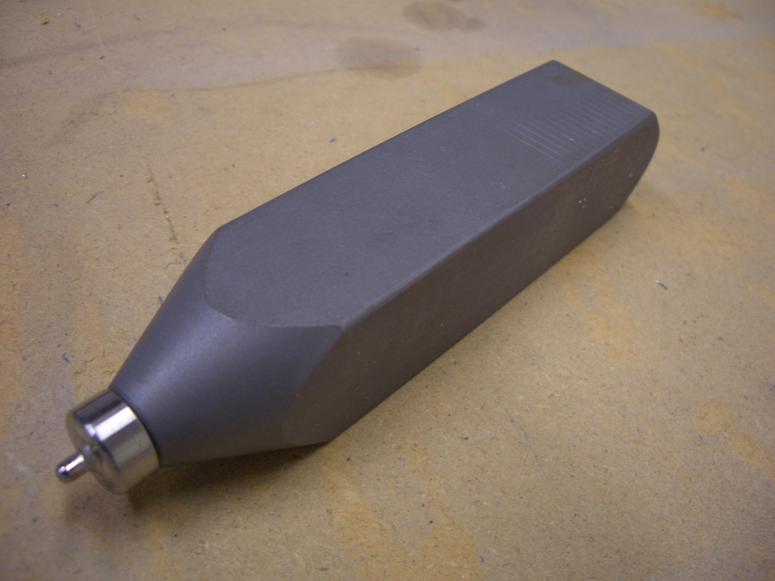
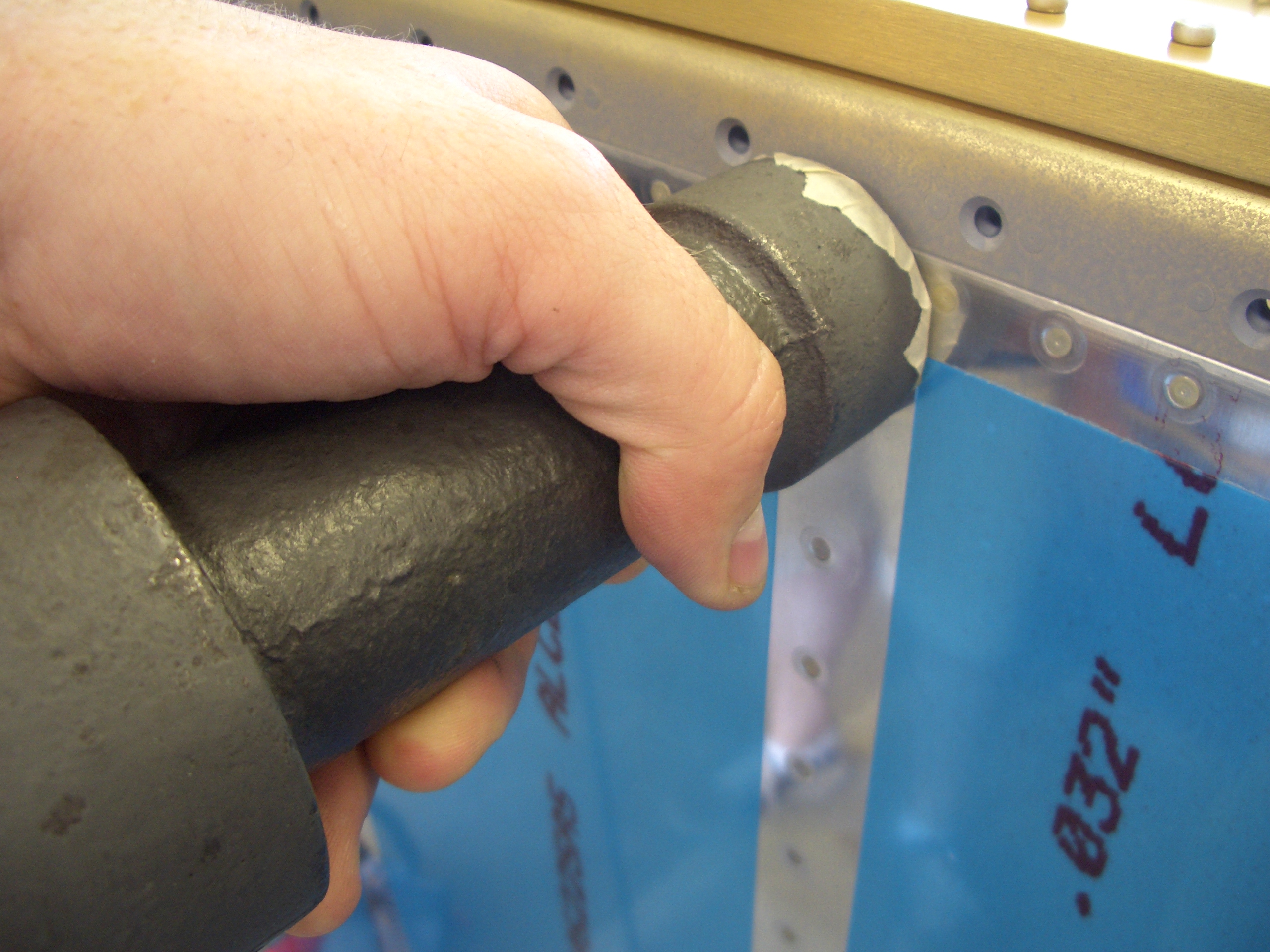
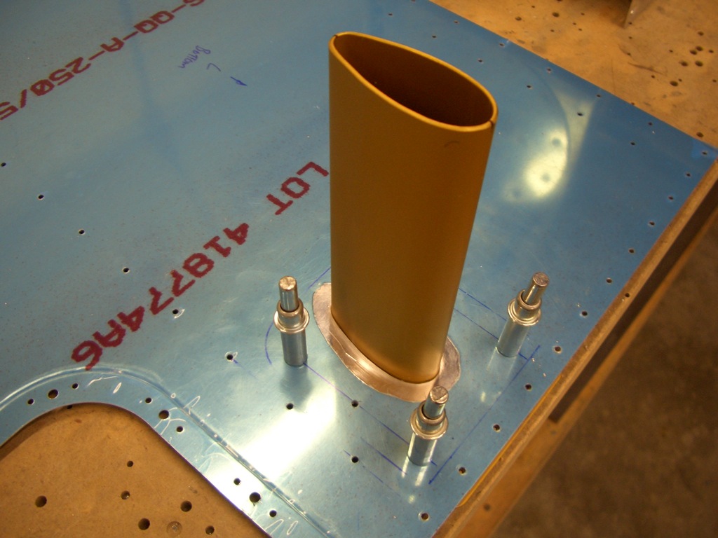
I test fit the pitot tube.  The 3/16″ aluminum tubes coming out the other end needed to be trimmed somewhat to allow the pitot tube to fit fully into the mount.

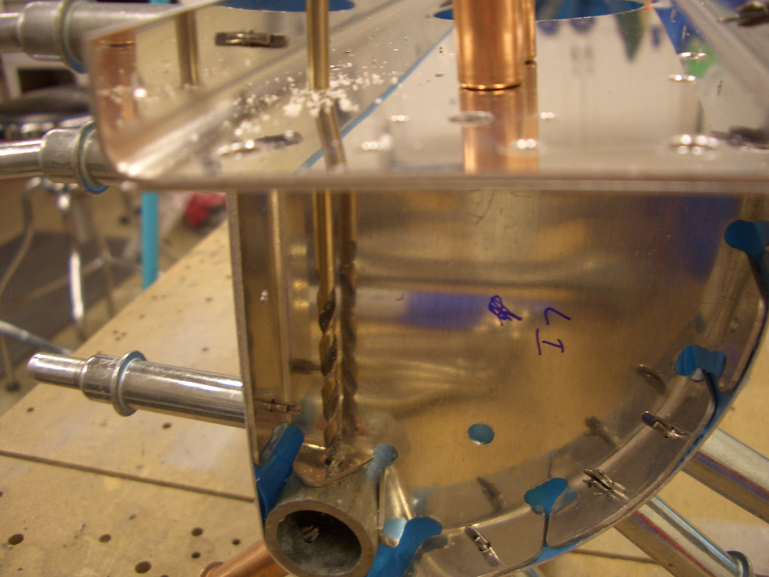
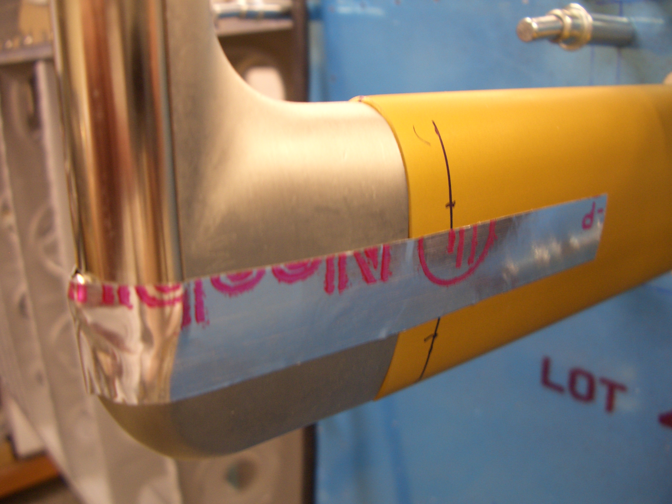
I laid out holes to attach the tube to the mount and used some aluminum tape as a clamp to hold the tube in place.

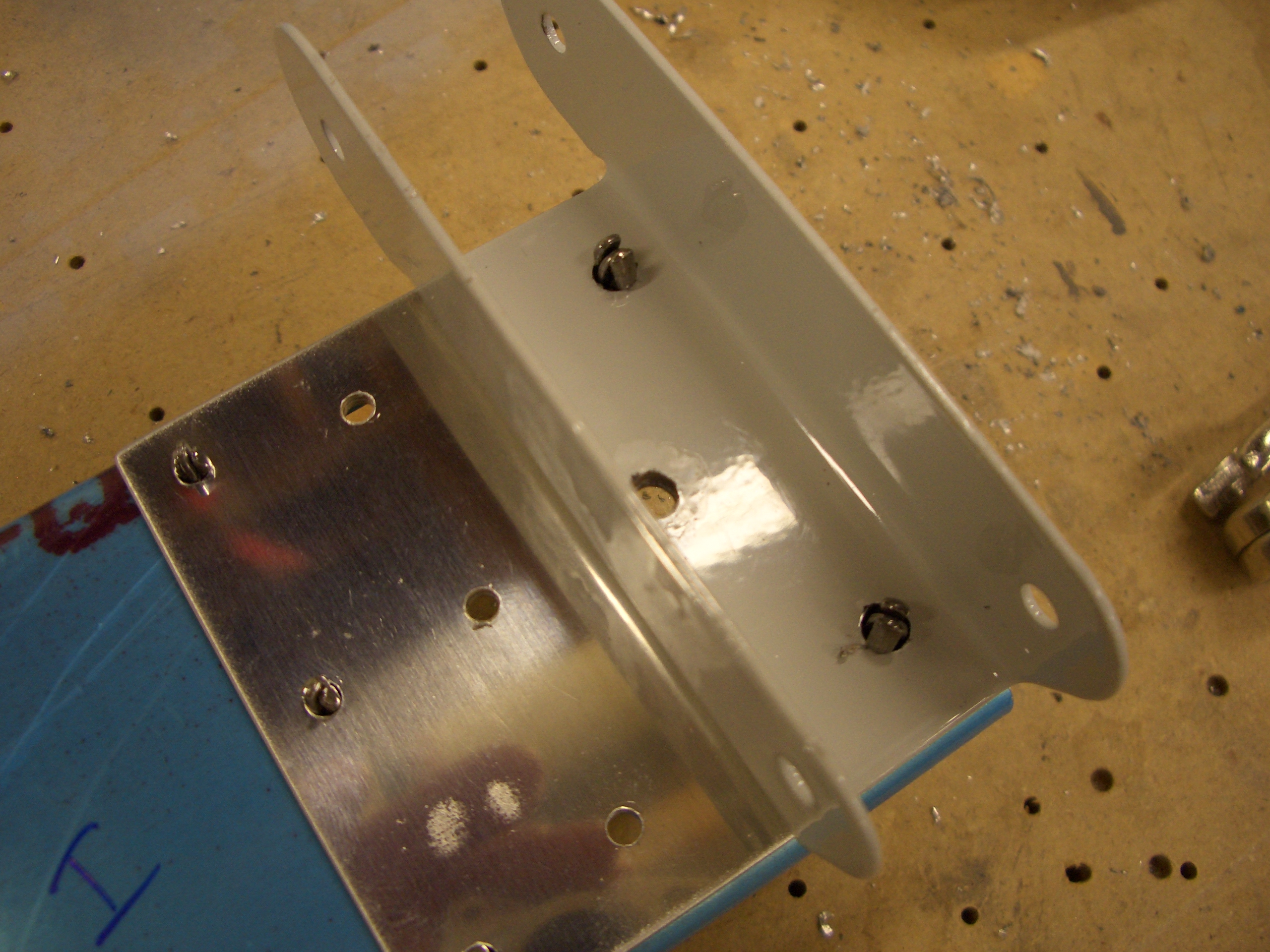
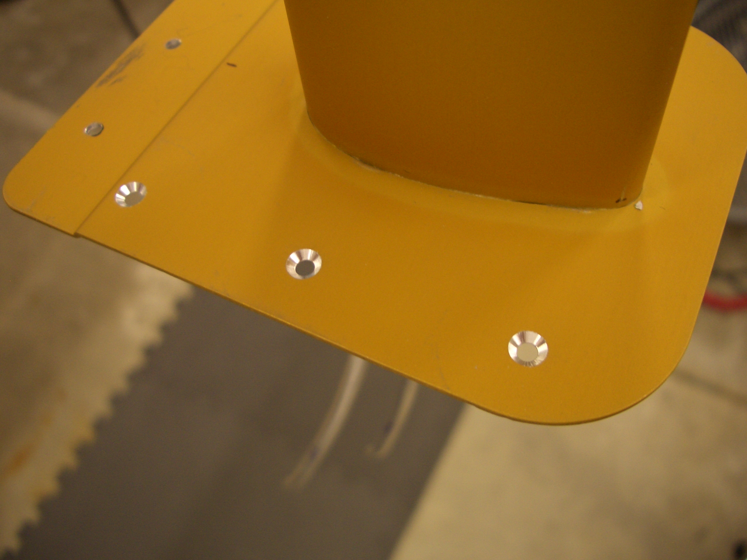
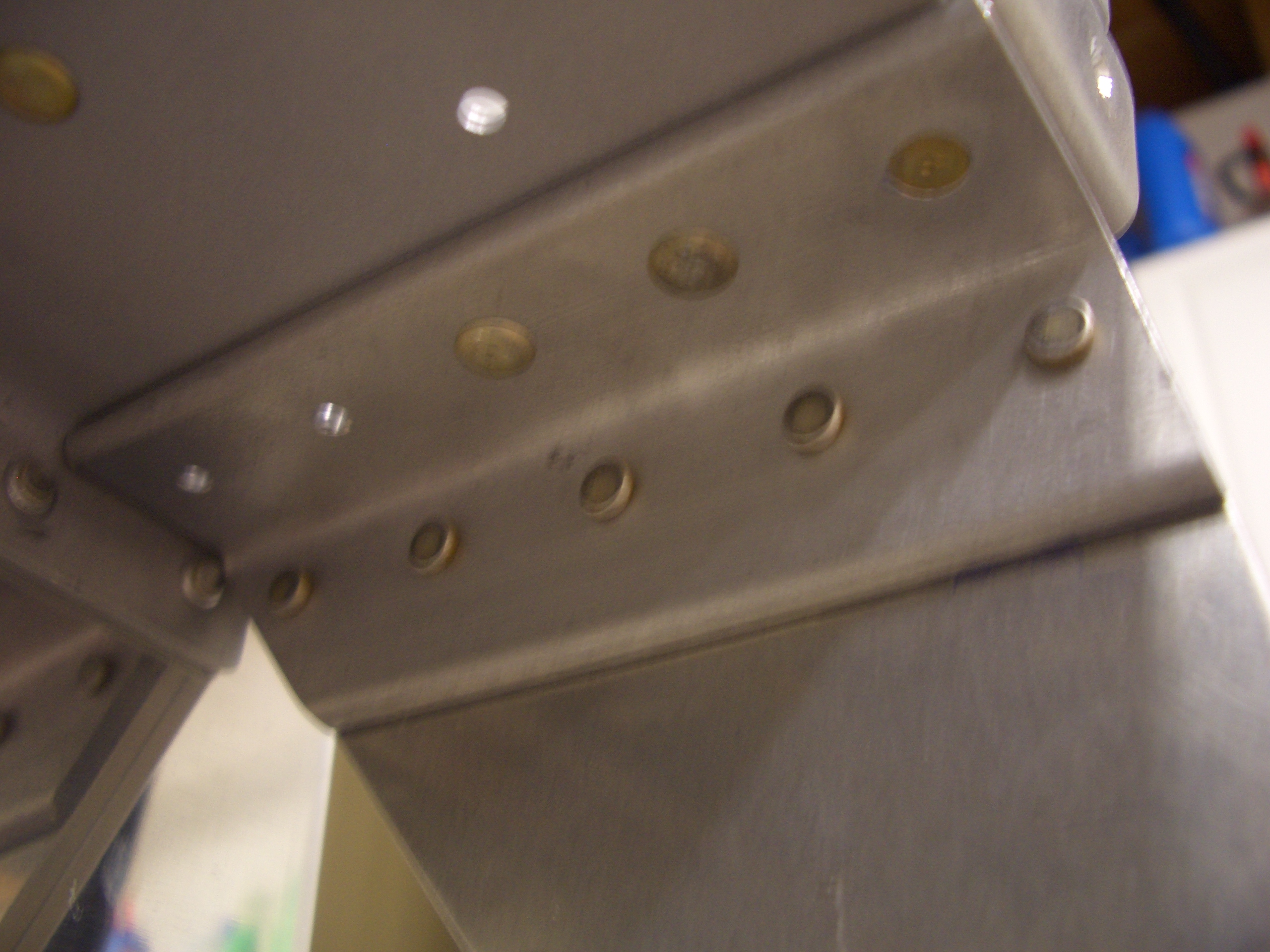
After drilling through the mount and the wall of the pitot tube, I countersunk the mount for #6 screws.  This was tricky since this is a curved surface.  Instead of using my microstop countersink, I basically just did these freehand.

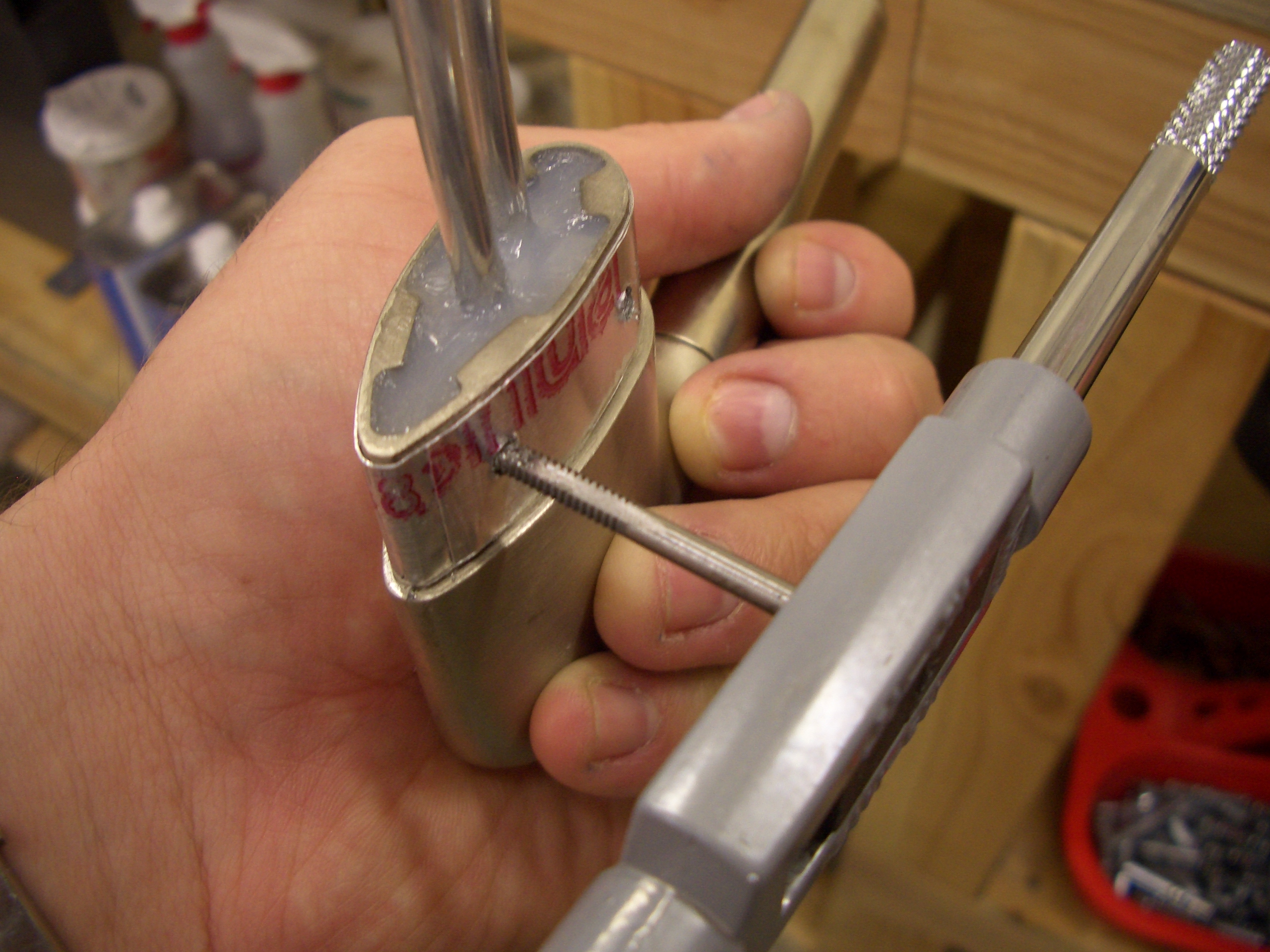
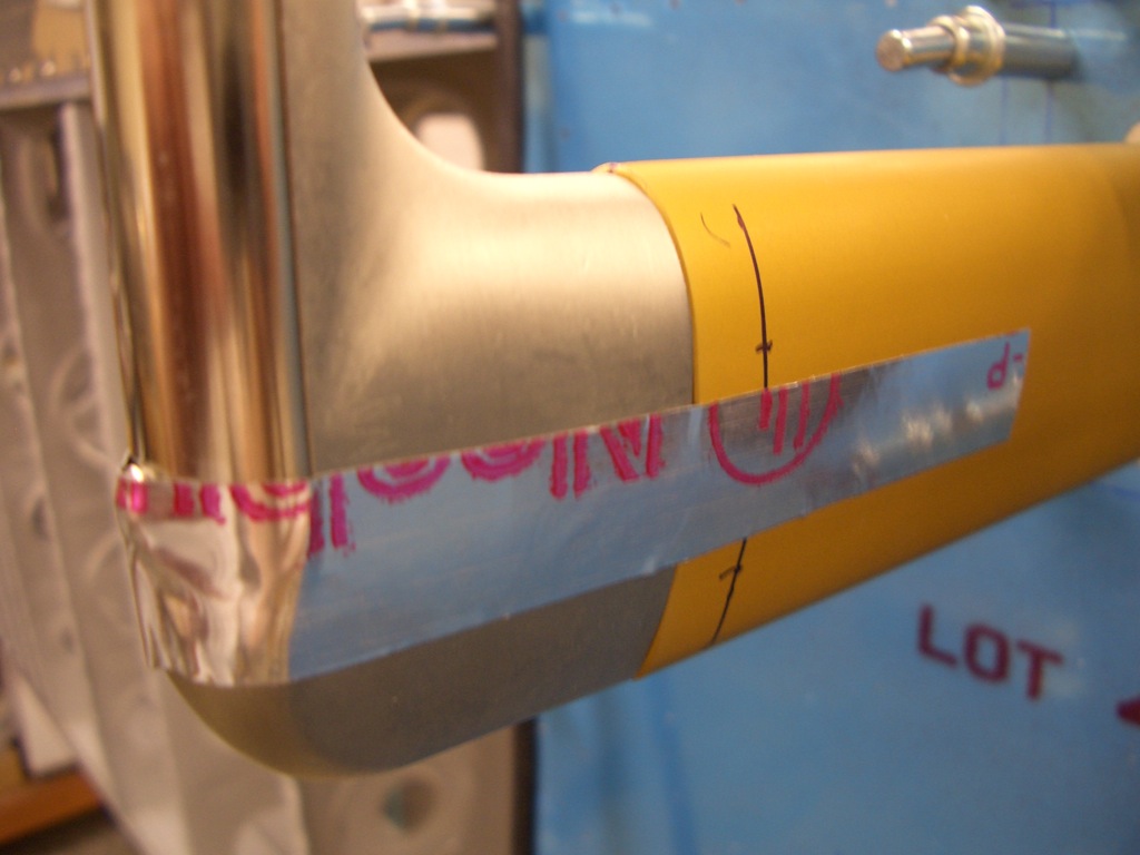
I also tapped the pitot tube for 6-32 threads.  The stuff with the red lettering on it is aluminum tape.  I wrapped this around the pitot tube because there was a little slop between it and the mount.

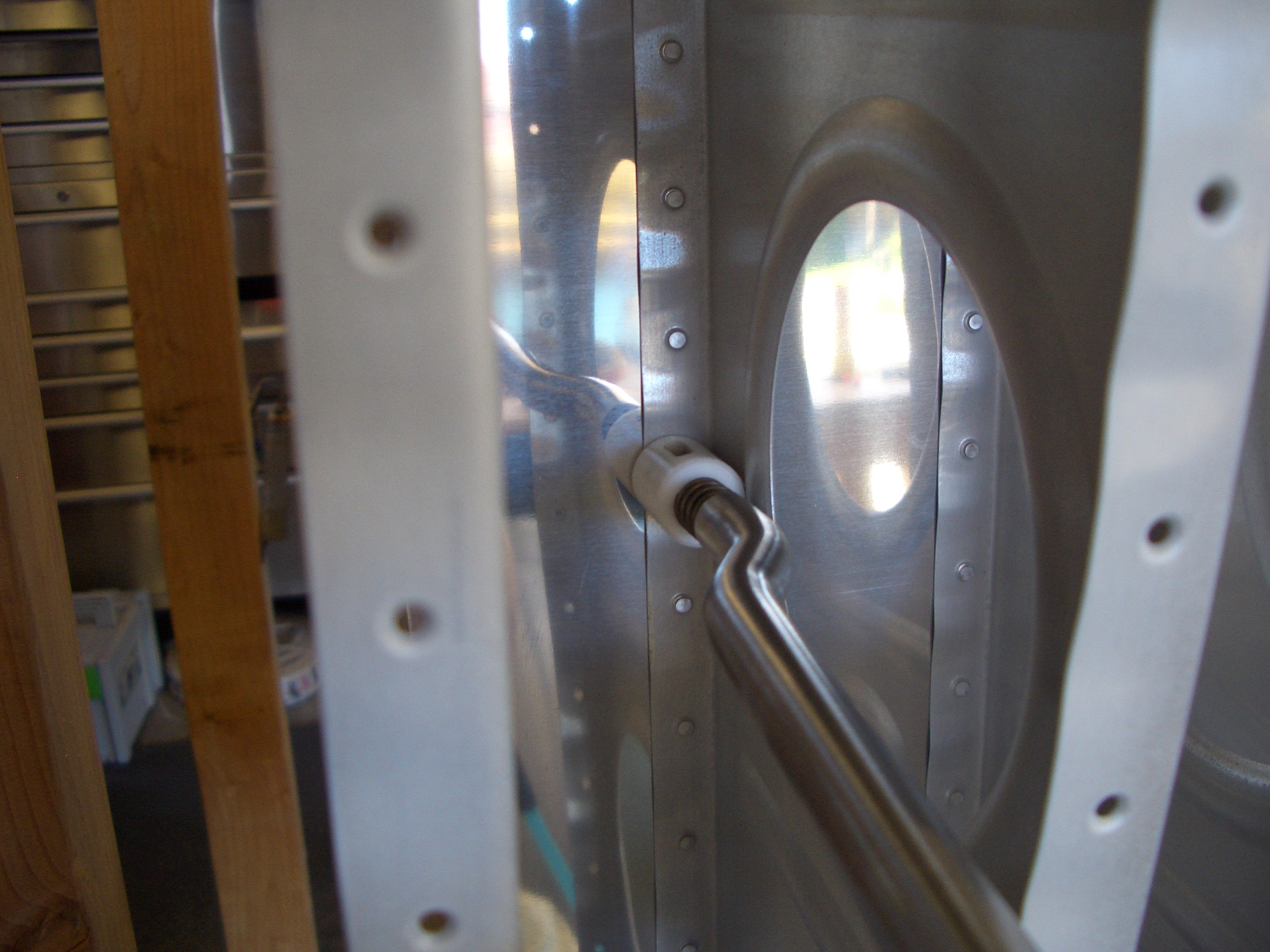
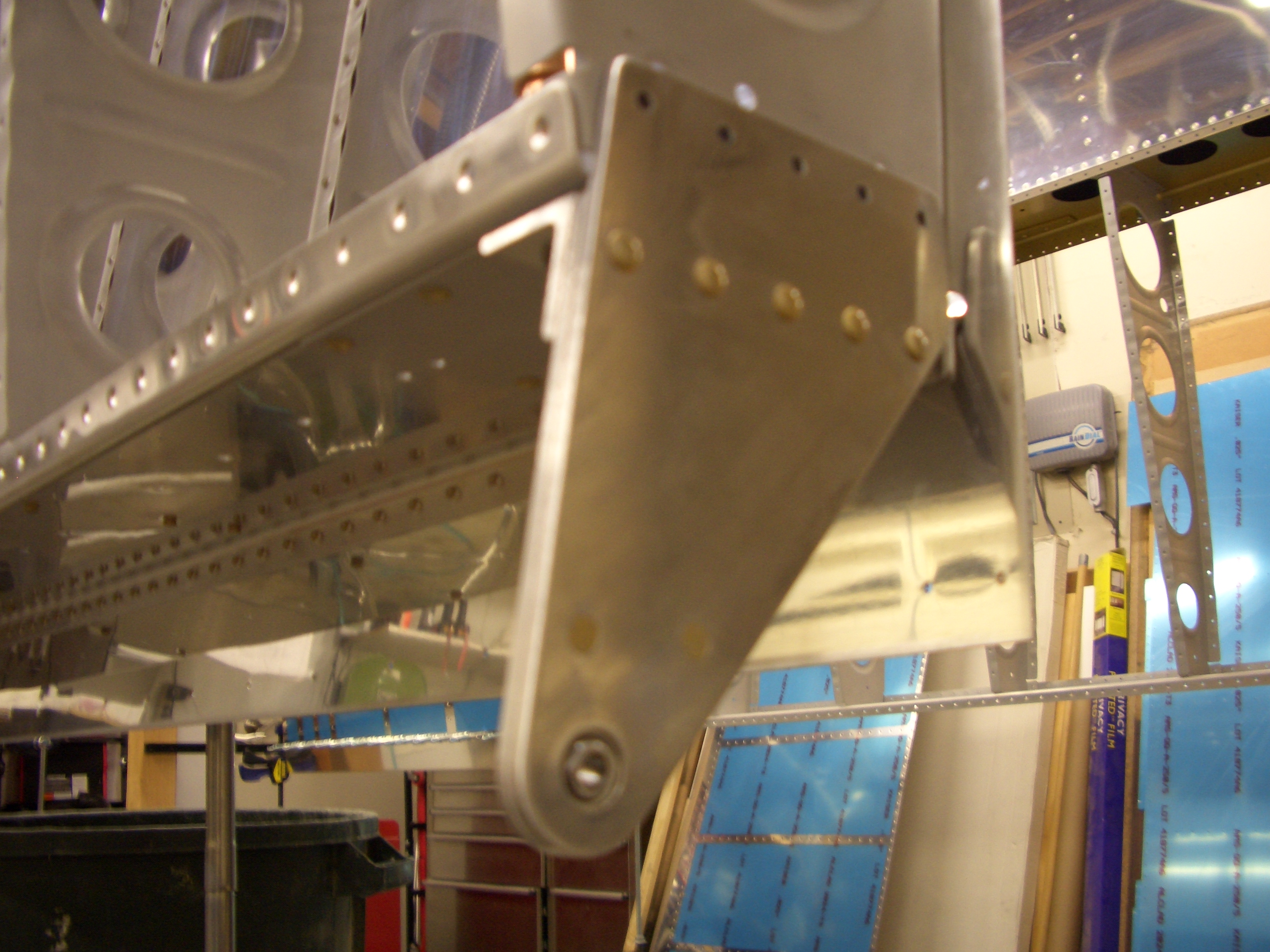
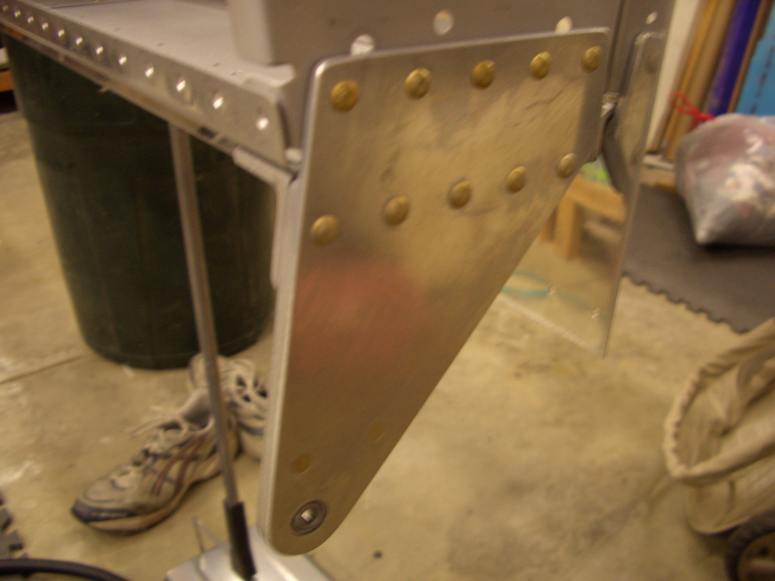
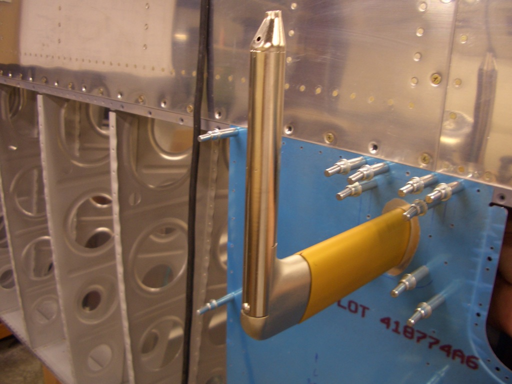
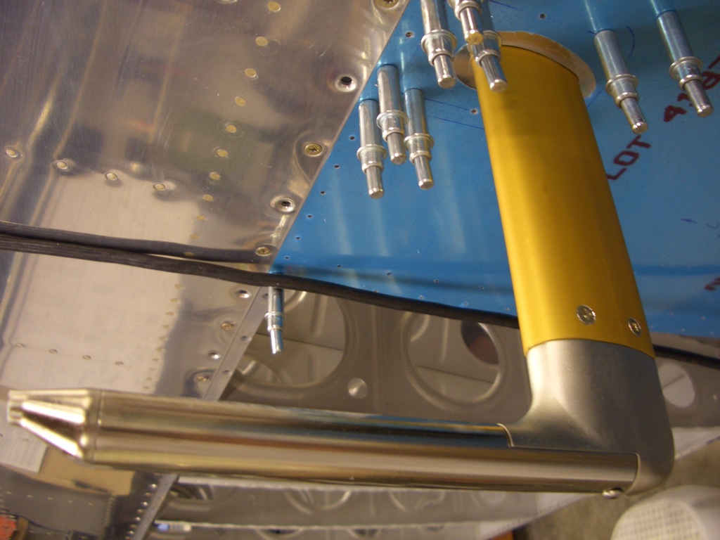
Here’s the finished pitot tube installed in the mount.  This really turned out well, the pitot tube is tight in the mount and the screws are nice and flush.

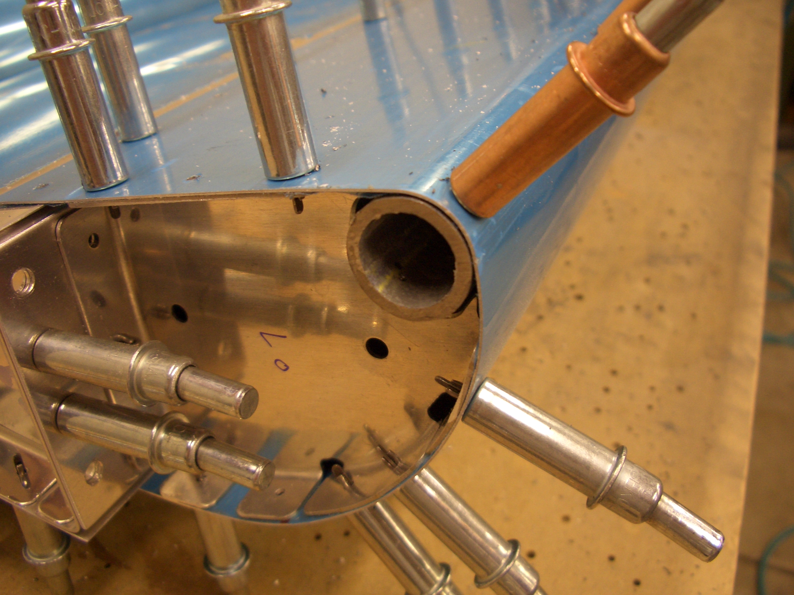
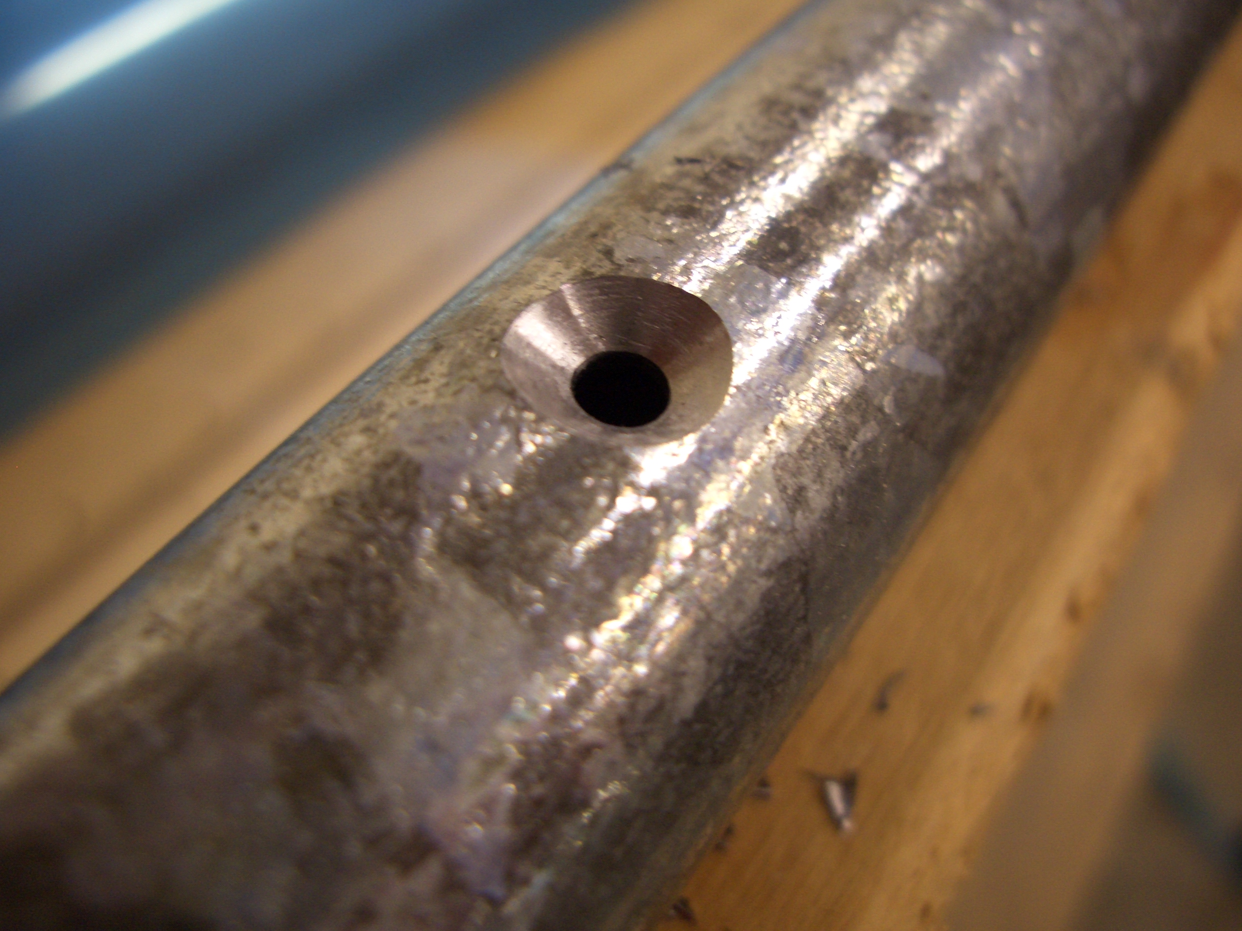
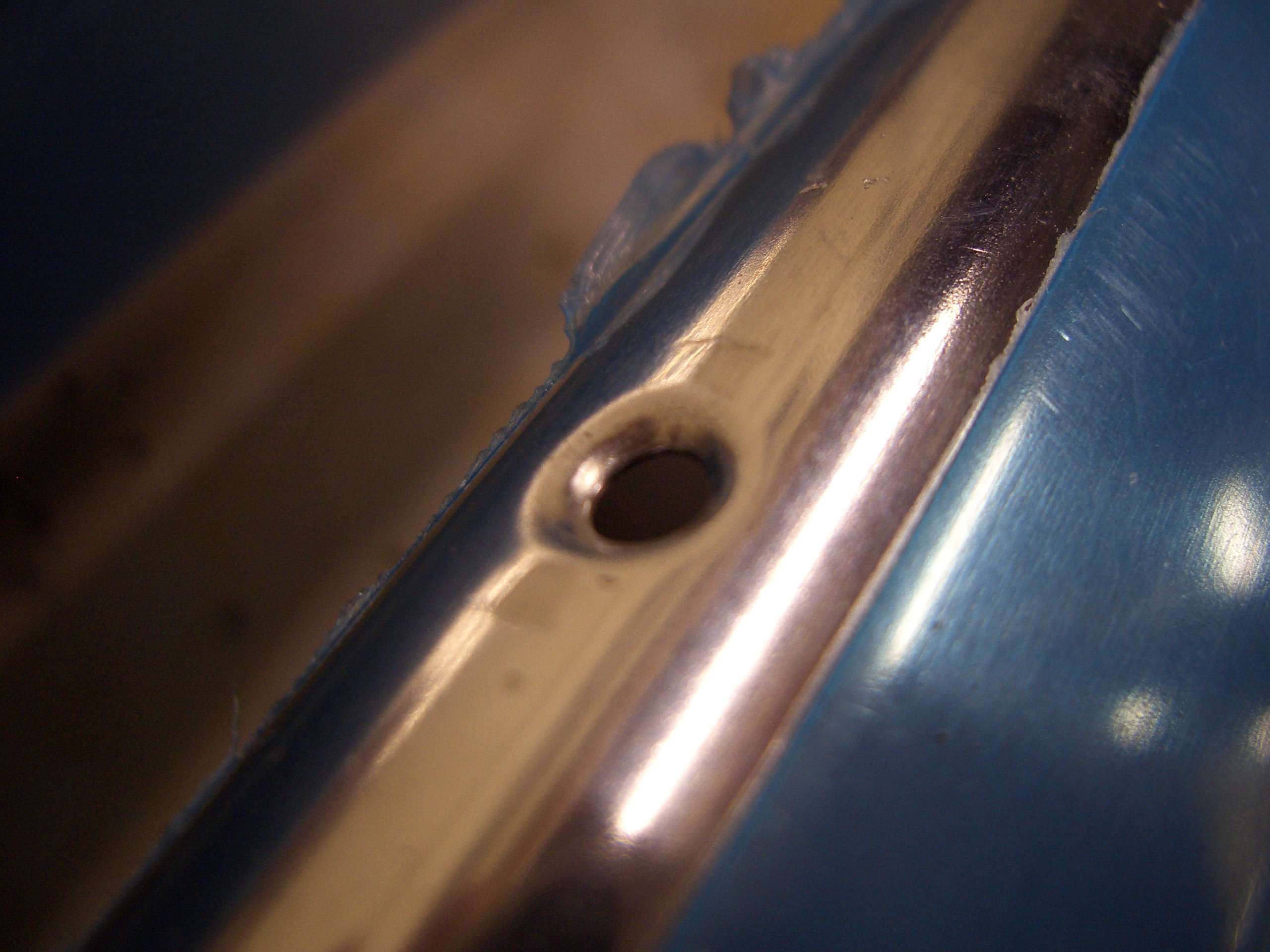
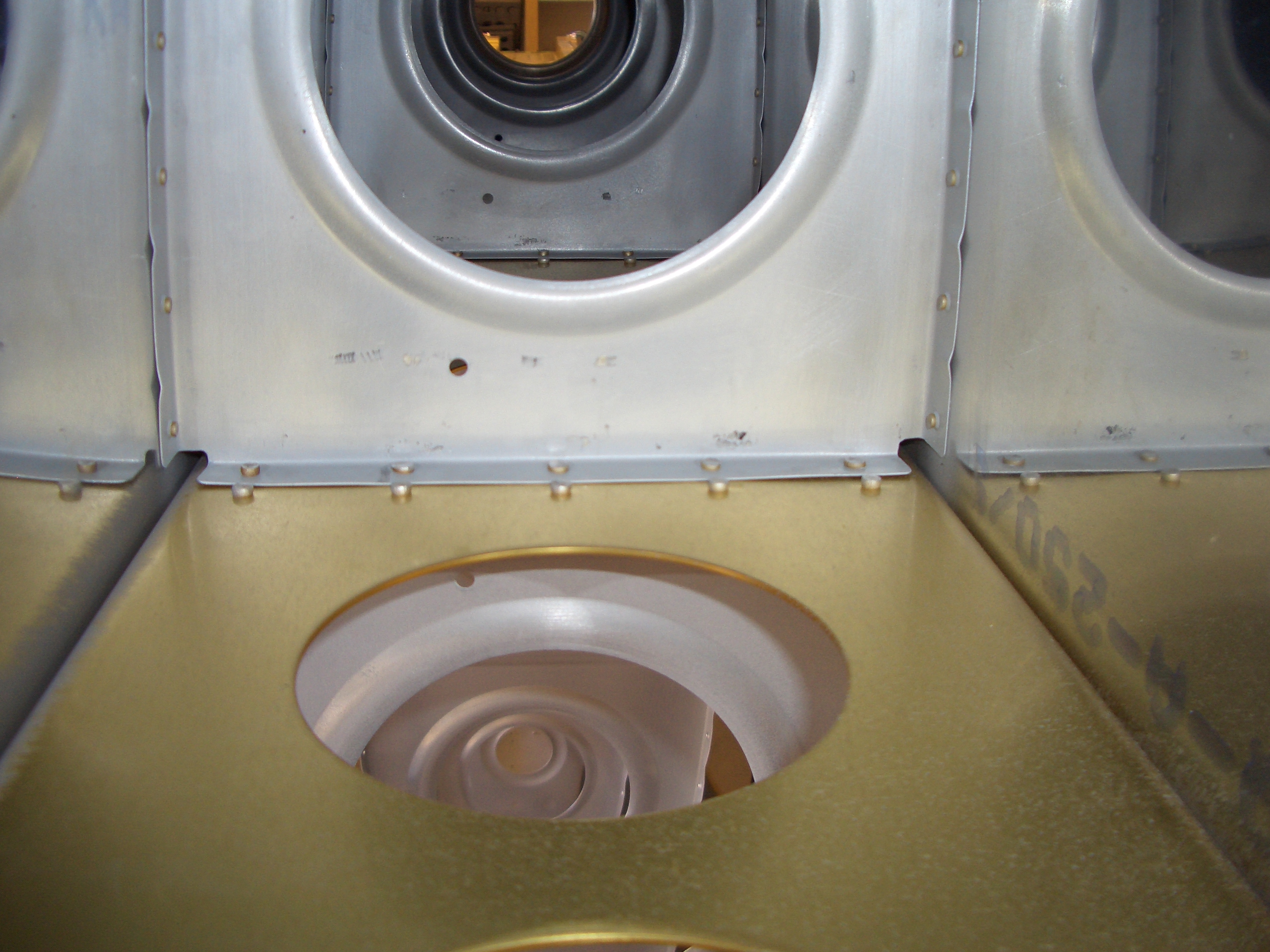
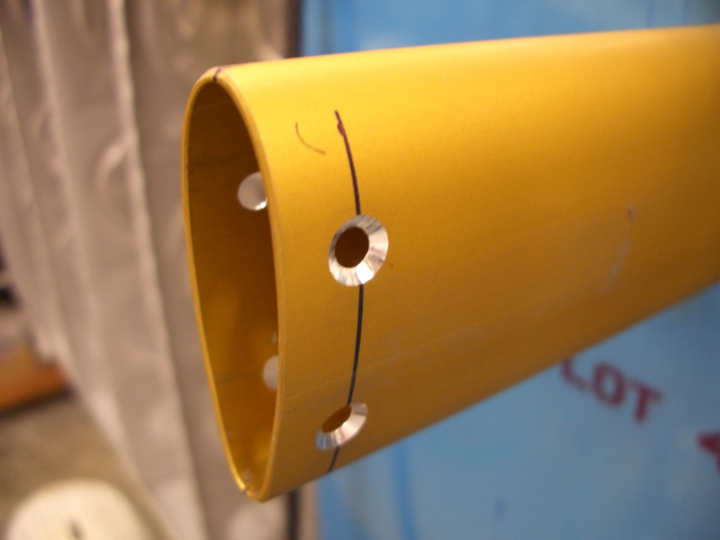
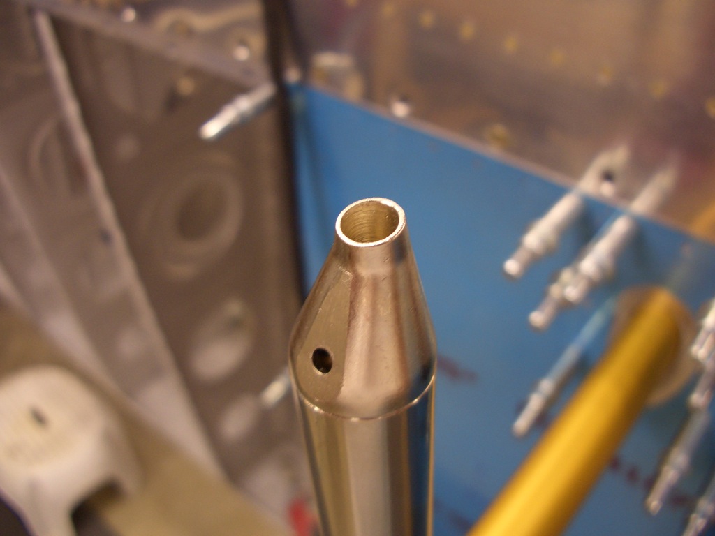
Here is the business end of the pitot tube.  The hole at the top is for measuring pitot pressure and the hole at the bottom is for measuring angle of attach.  Basically, as the wing’s angle of attach increases, this hole becomes more directly aligned into the wind.  This increases the pressure of air inside this tube which the instrument indicates as an increase in angle of attach.

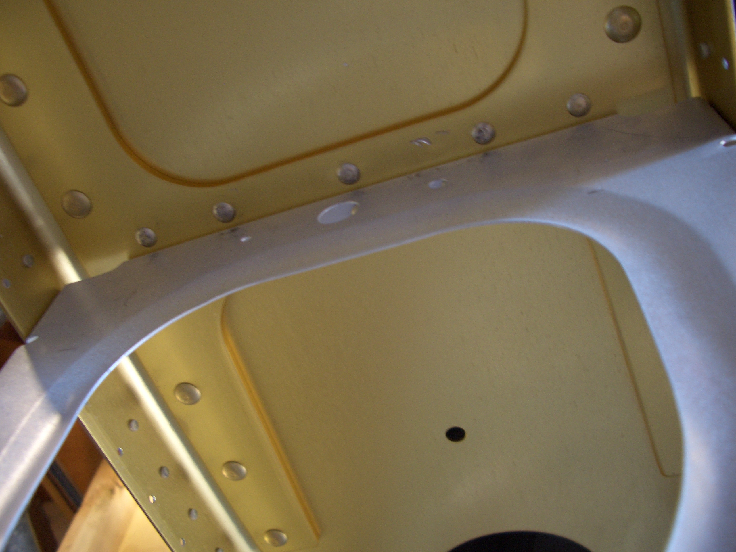
I disassembled everything and countersink the pitot mount for the dimples in the skin since this will be flush mounted.

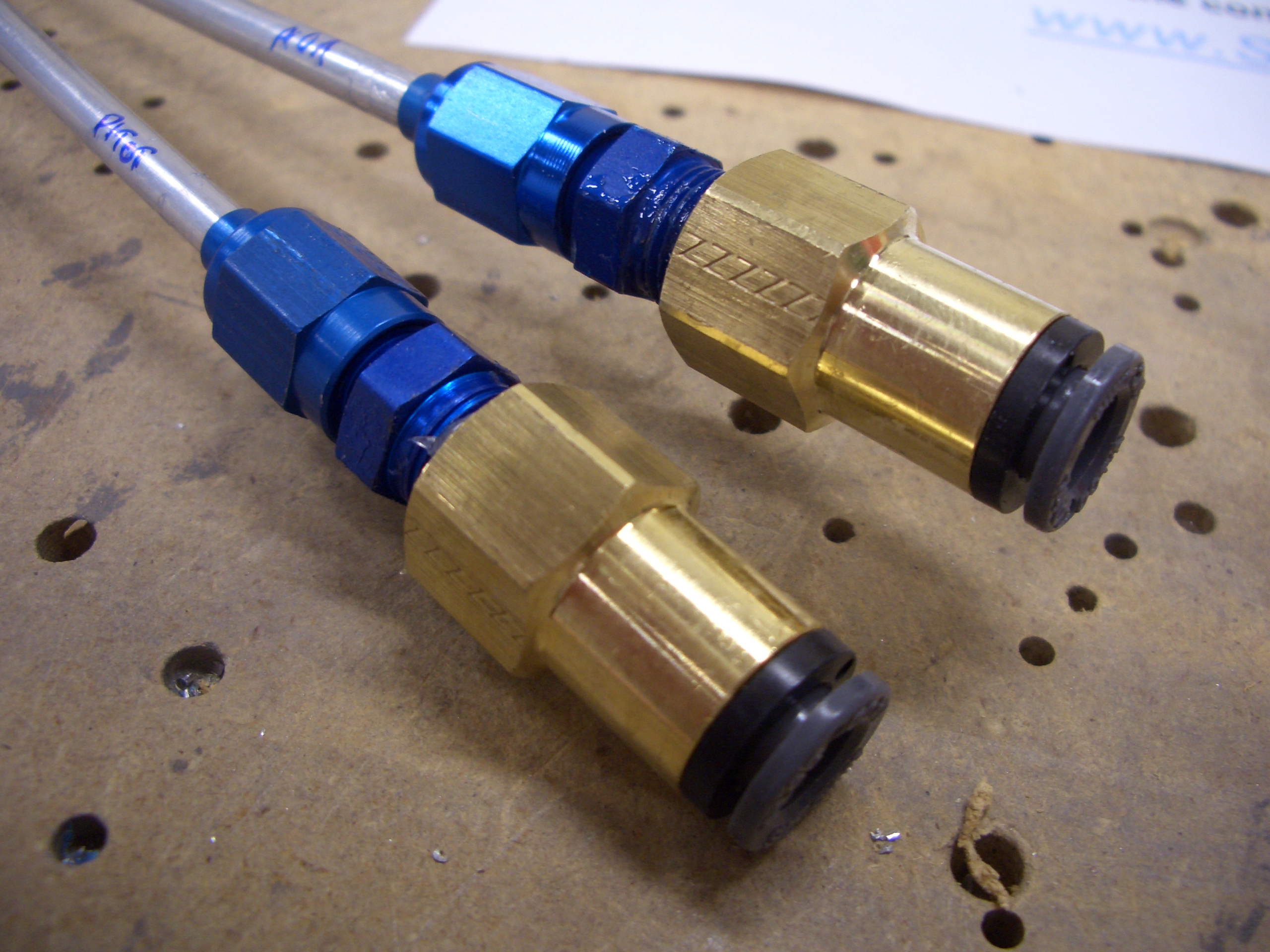
I cut the 3/16″ aluminum lines on the pitot tube shorter so that they just stick out of the mount in the wing, then installed fittings and flared the ends.

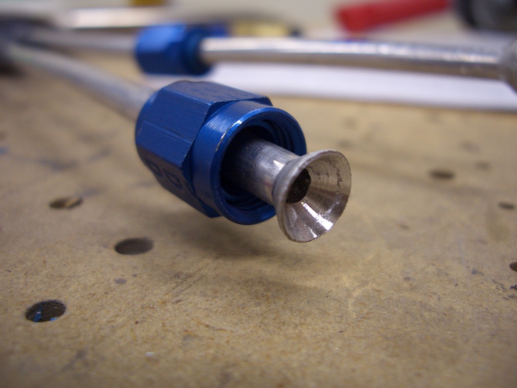
The male end of the fitting is installed and torqued.

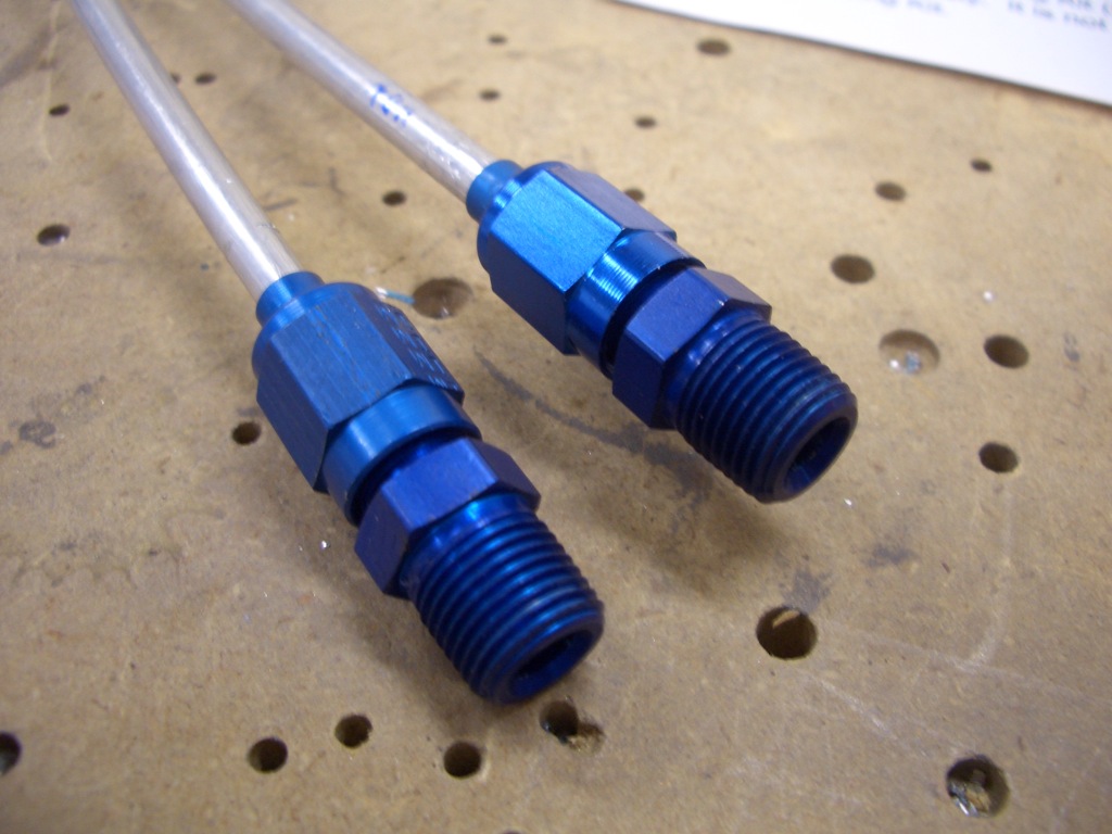
Using some EZ-Turn, I then installed the quick disconnects on the ends.  The tubing I’m using will just push into place on these fittings.

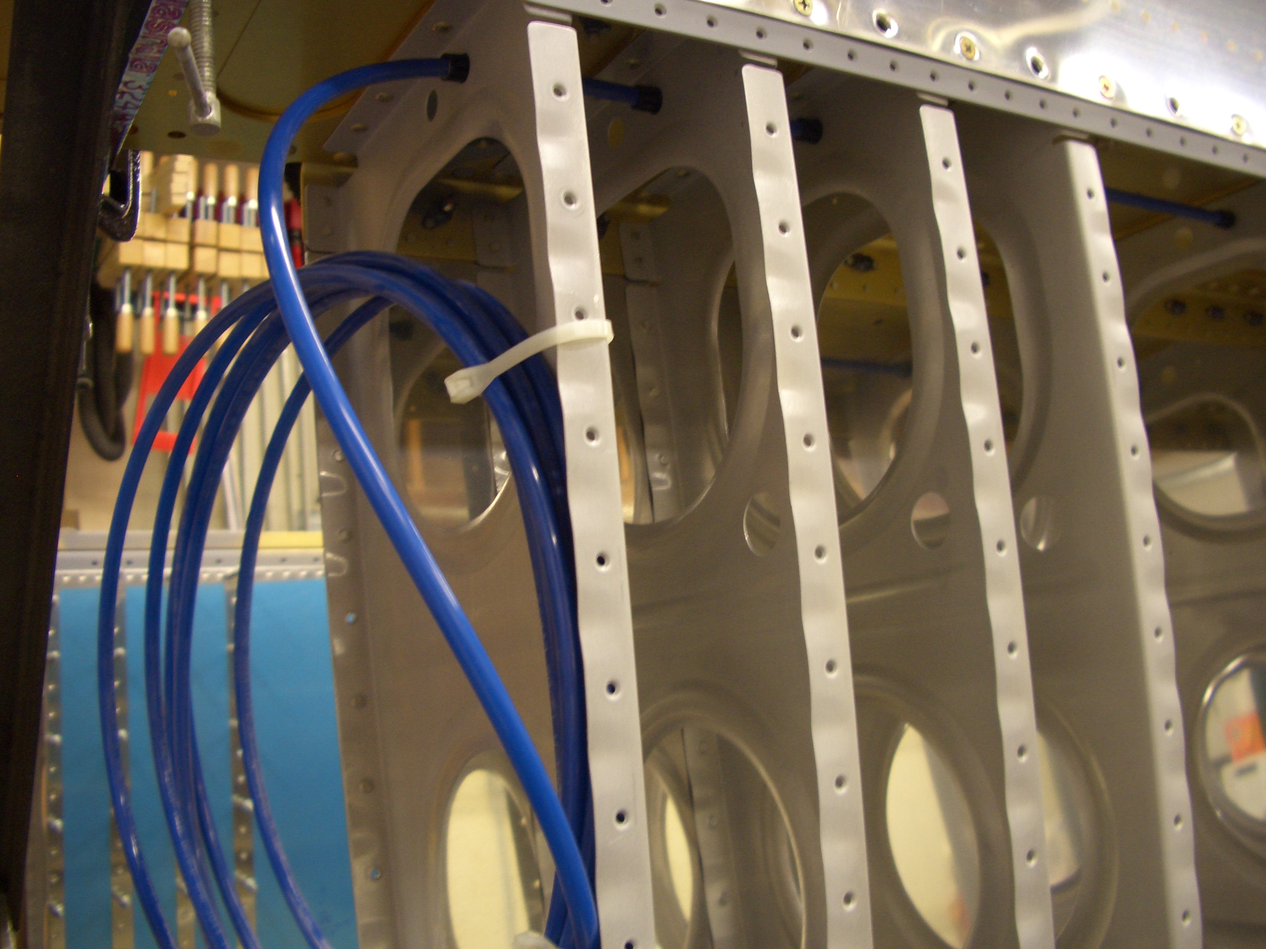
Finally, I installed the AOA tubing in the wing.  I didn’t have enough 437-4 snap bushings to install the pitot tubing, so that will wait until I order some.

Miscellaneous Wing Tasks

I started pulling the conduit through the wing ribs on the left wing, but it turns out that this makes a hell of a racket.  Since the kids were asleep, I put this off and moved on to something else.

I went ahead and squeezed the rivets on the right wing outboard leading edge.  I still have to rivet the ribs to the spar, but that has to wait until I have a riveting partner.

I deburred the edges of the flap brace and trimmed it to clear the rear spar doubler.jk

I clecoed on the flap brace (on the left) and the inboard aileron hinge bracket (center) and match drilled them.

I also clecoed and match drilled the outboard aileron hinge bracket.

After deburring and priming the mating surfaces, I riveted the aileron hinge brackets on (though only the rivets I could reach with a squeezer since it was late).

Here is the rear part of the outboard aileron bracket. Notice that the lower hole (right in this picture) needs a countersunk rivet. This is to clear the leading edge of the aileron since it comes very close to the bracket here.