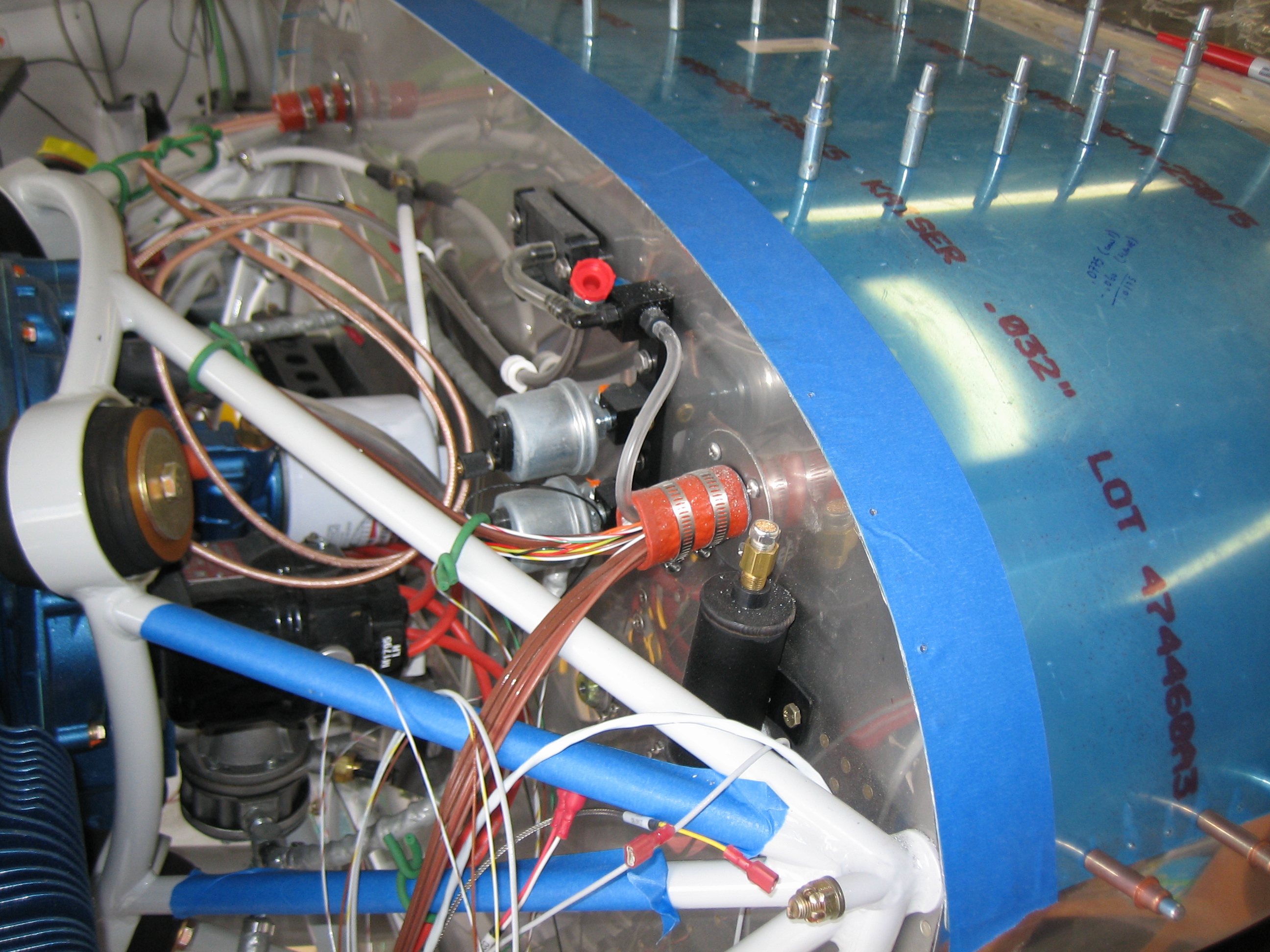
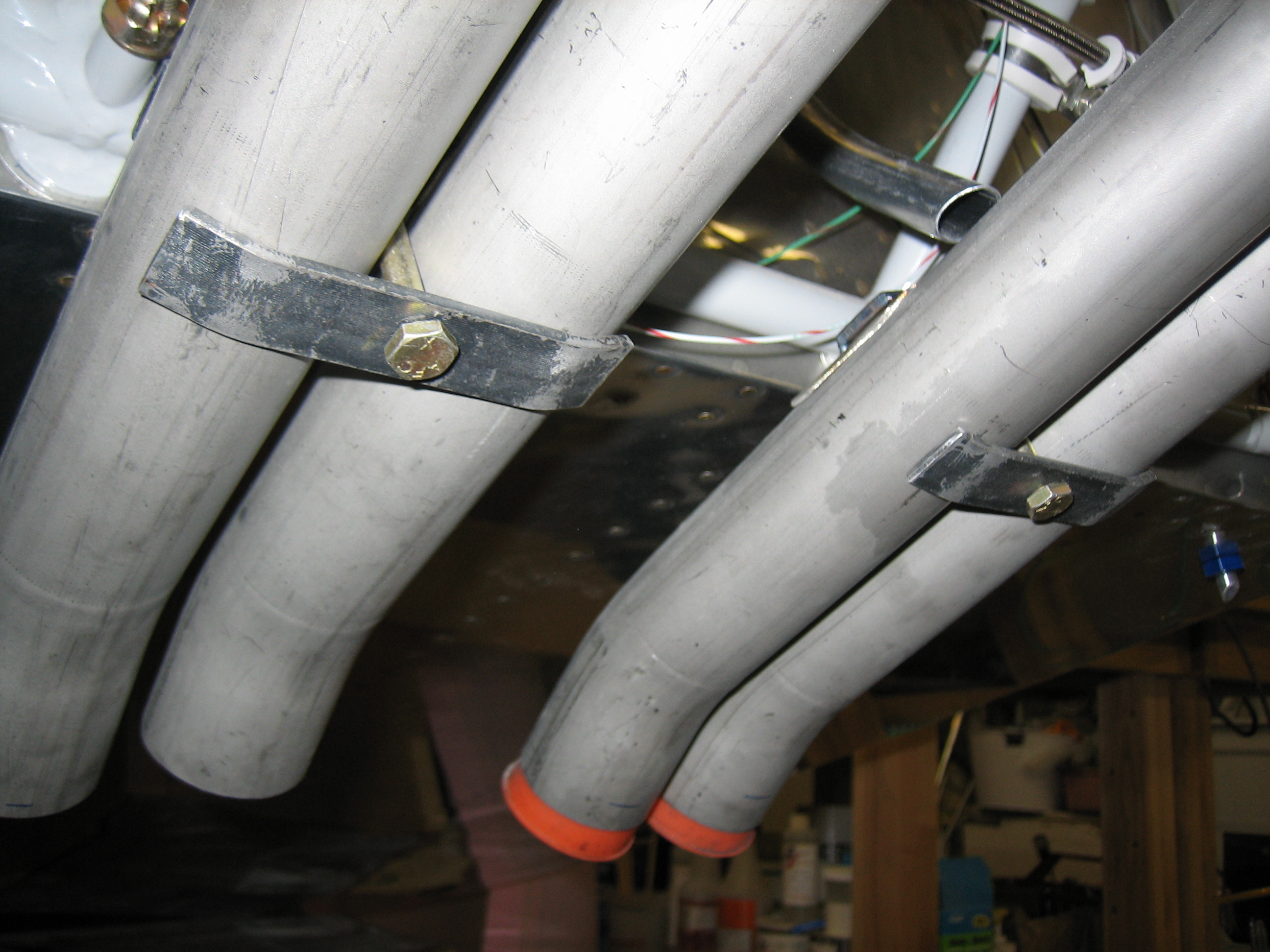
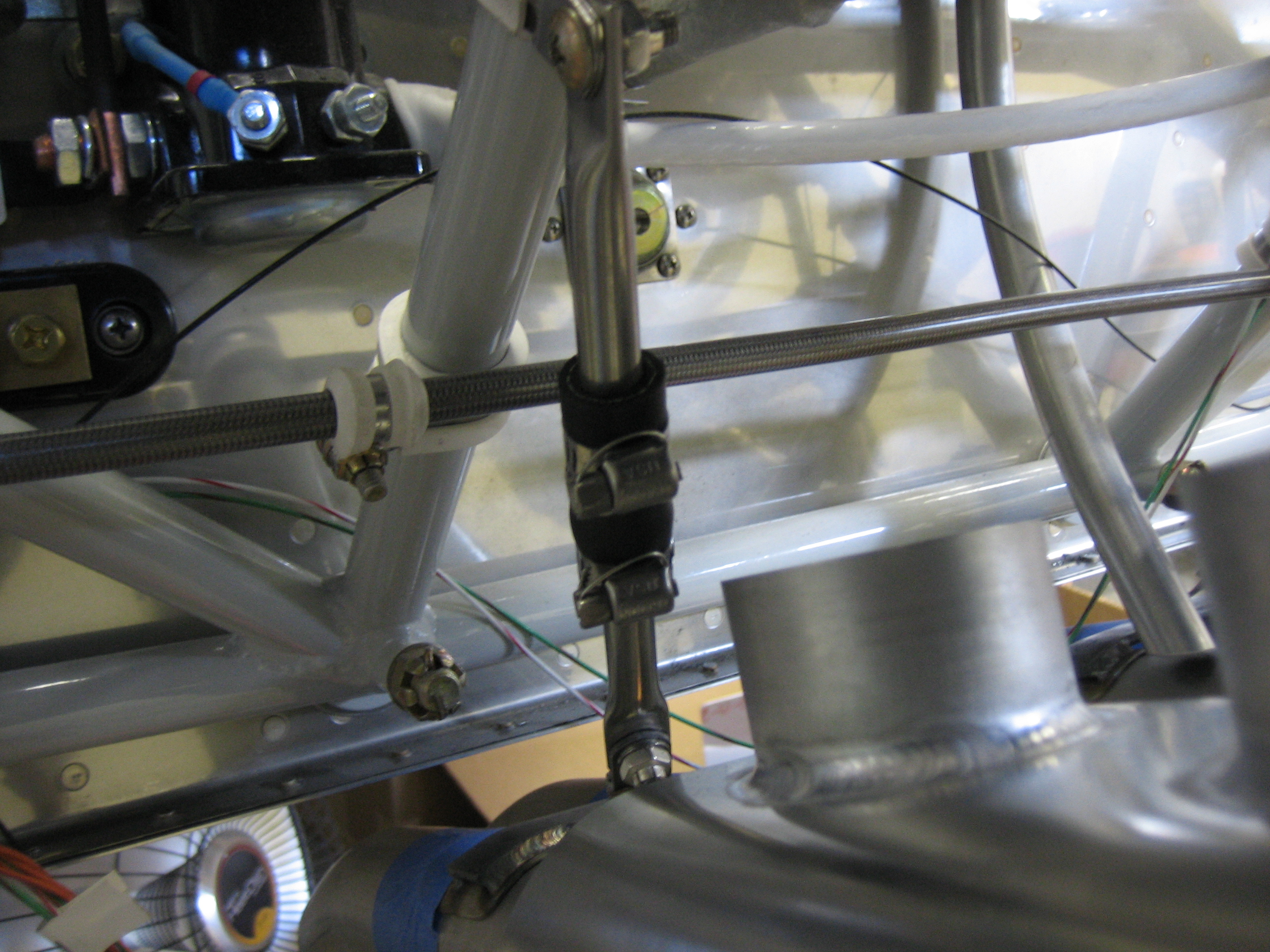
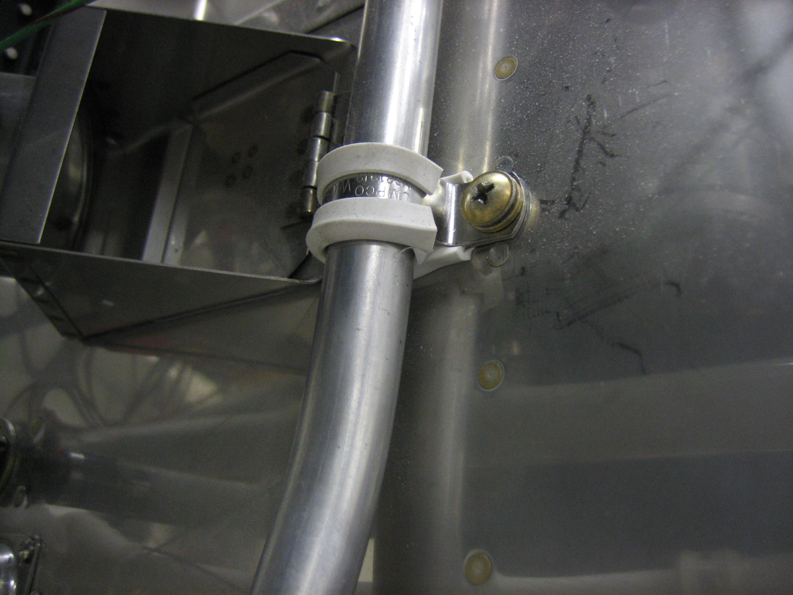
I loosely installed the fuel tank support brackets, mostly to get the brackets off my bench and out of the way. These will need to be tweaked to align with the fuel tank brackets once the wings are mounted, so there is no sense torquing these bolts down right now.

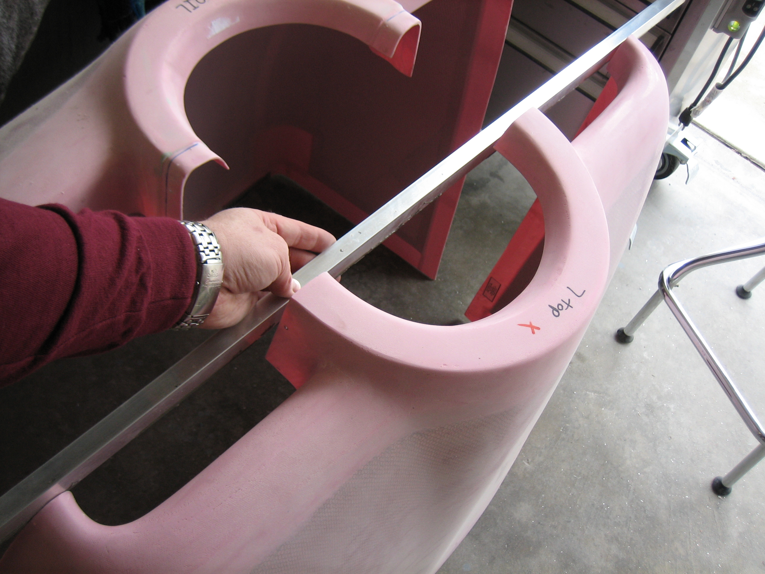
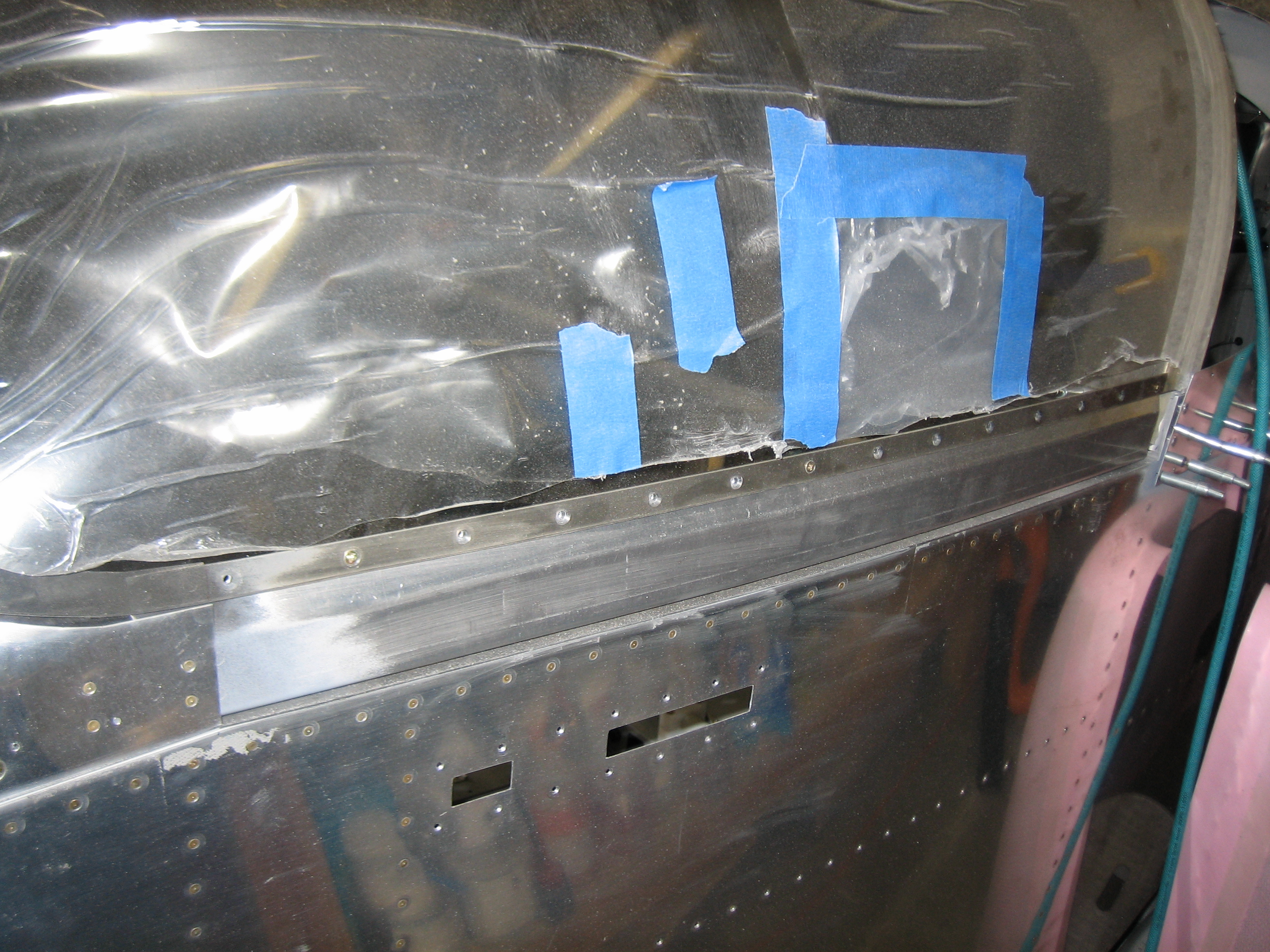
Back to work on the upper cowl, I broke out the die grinder and cutoff wheel and cut out the opening for the oil door. This needs to be removed now so that you have access to the inside of the cowl when fitting the upper hinge pin.
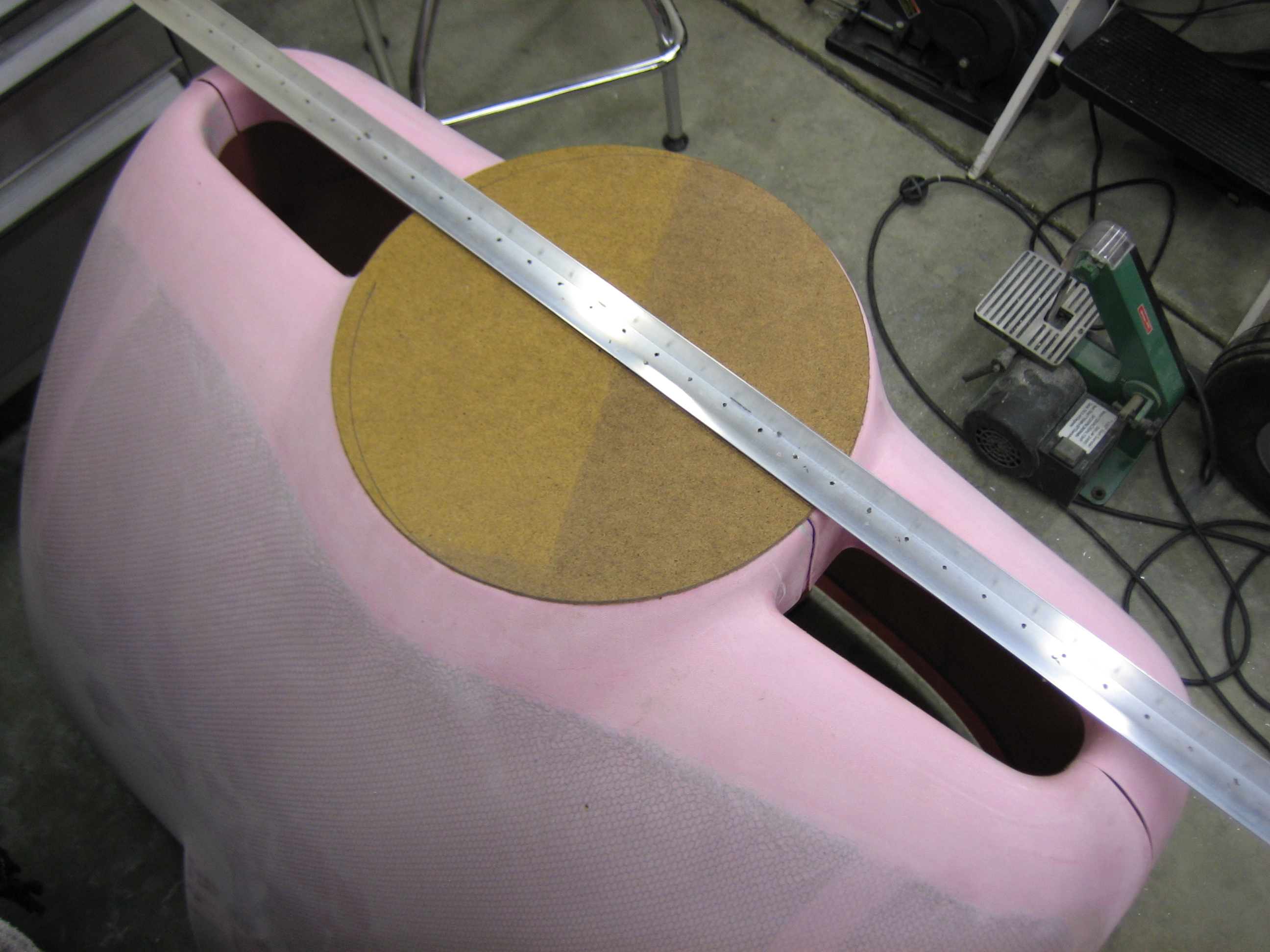
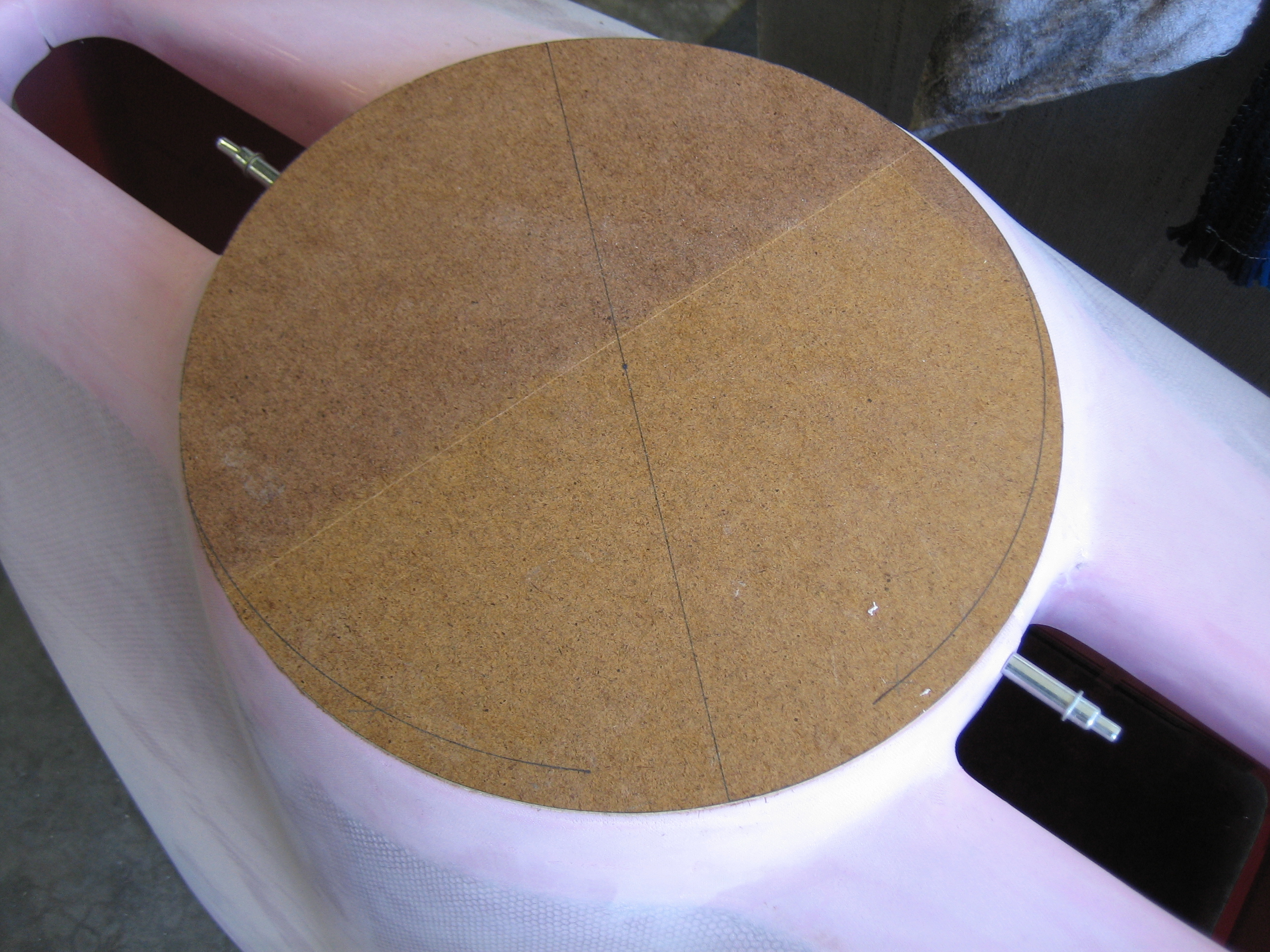
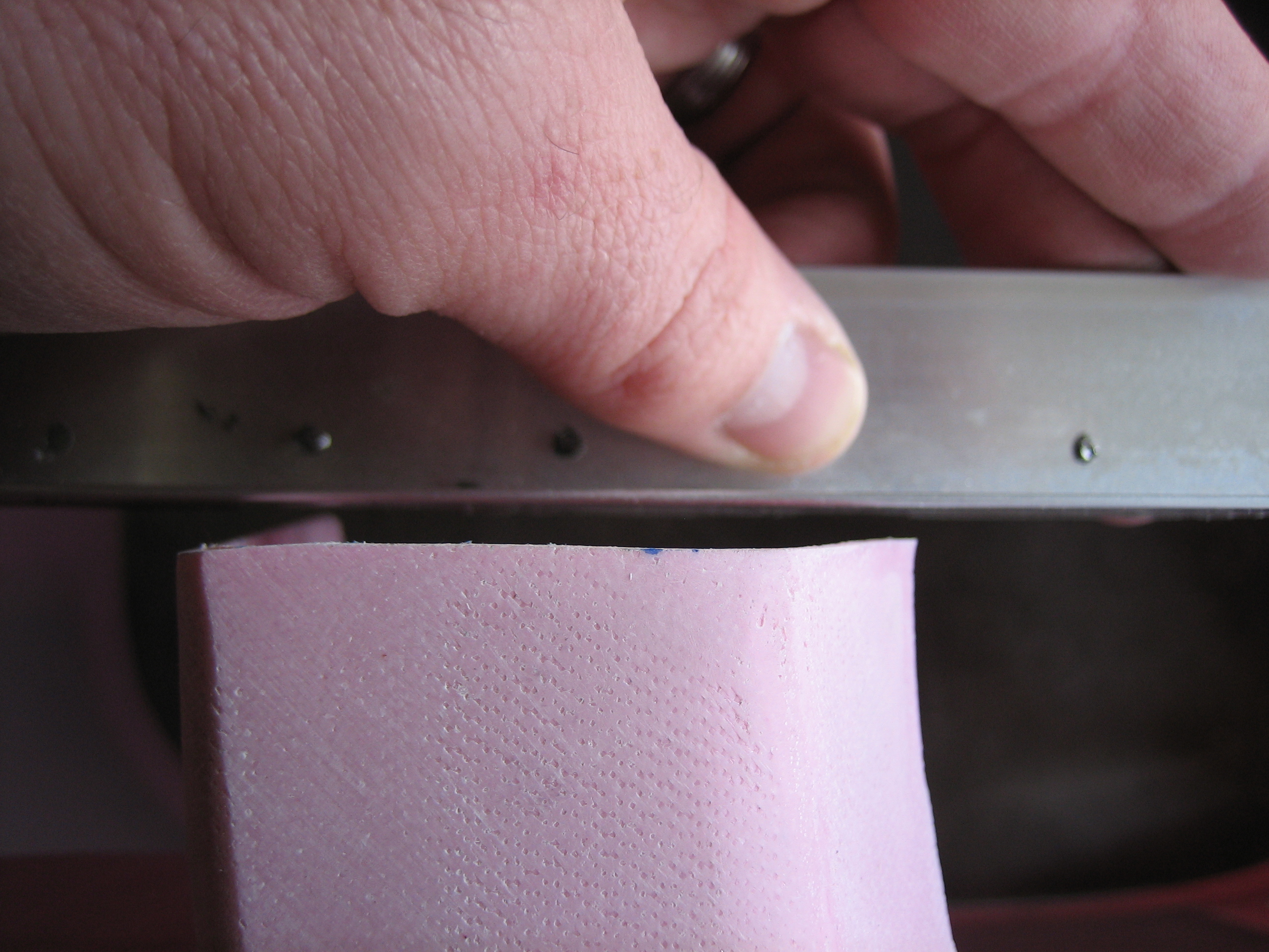
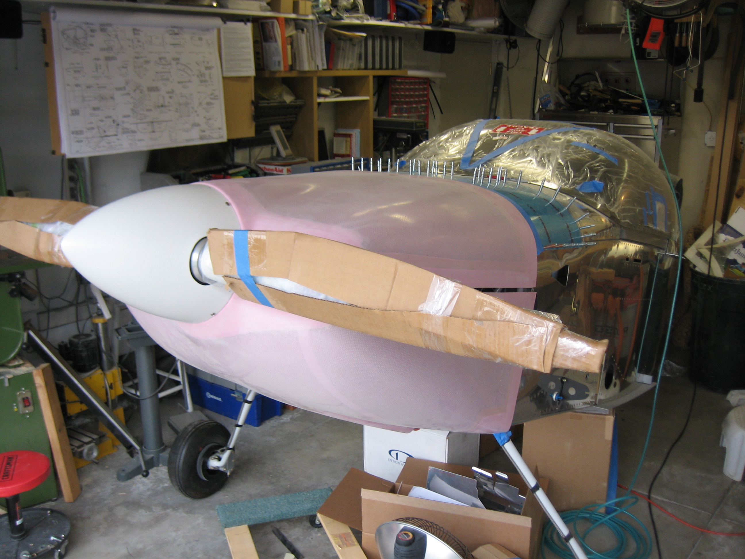
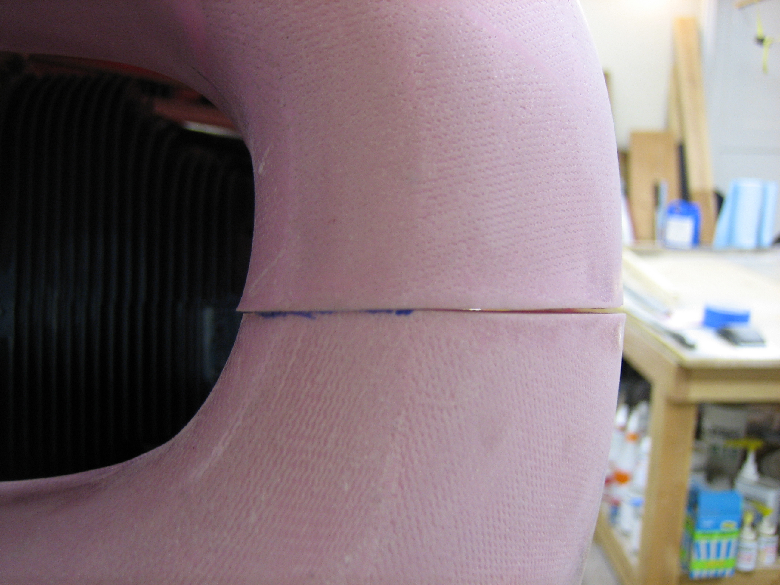
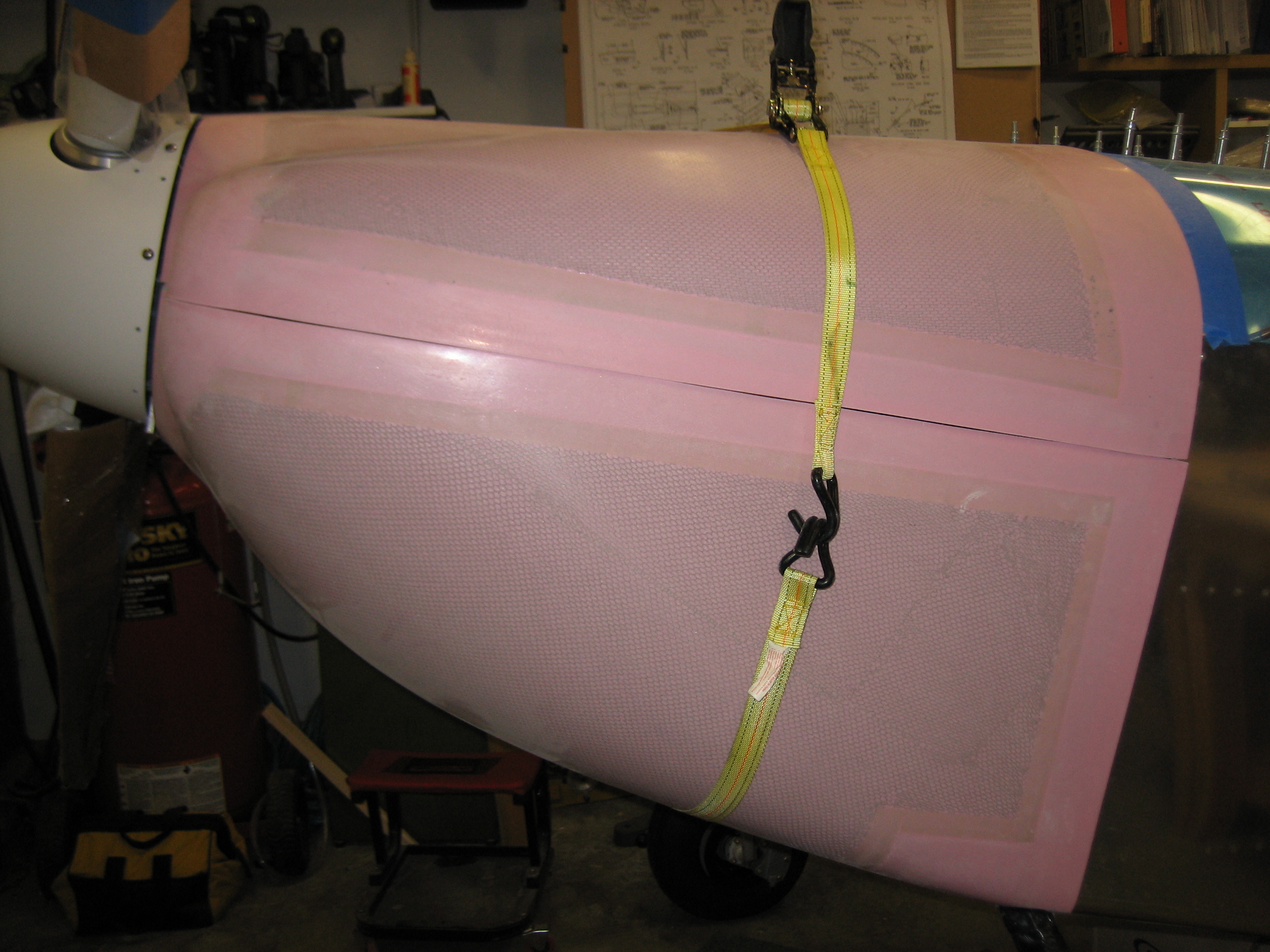
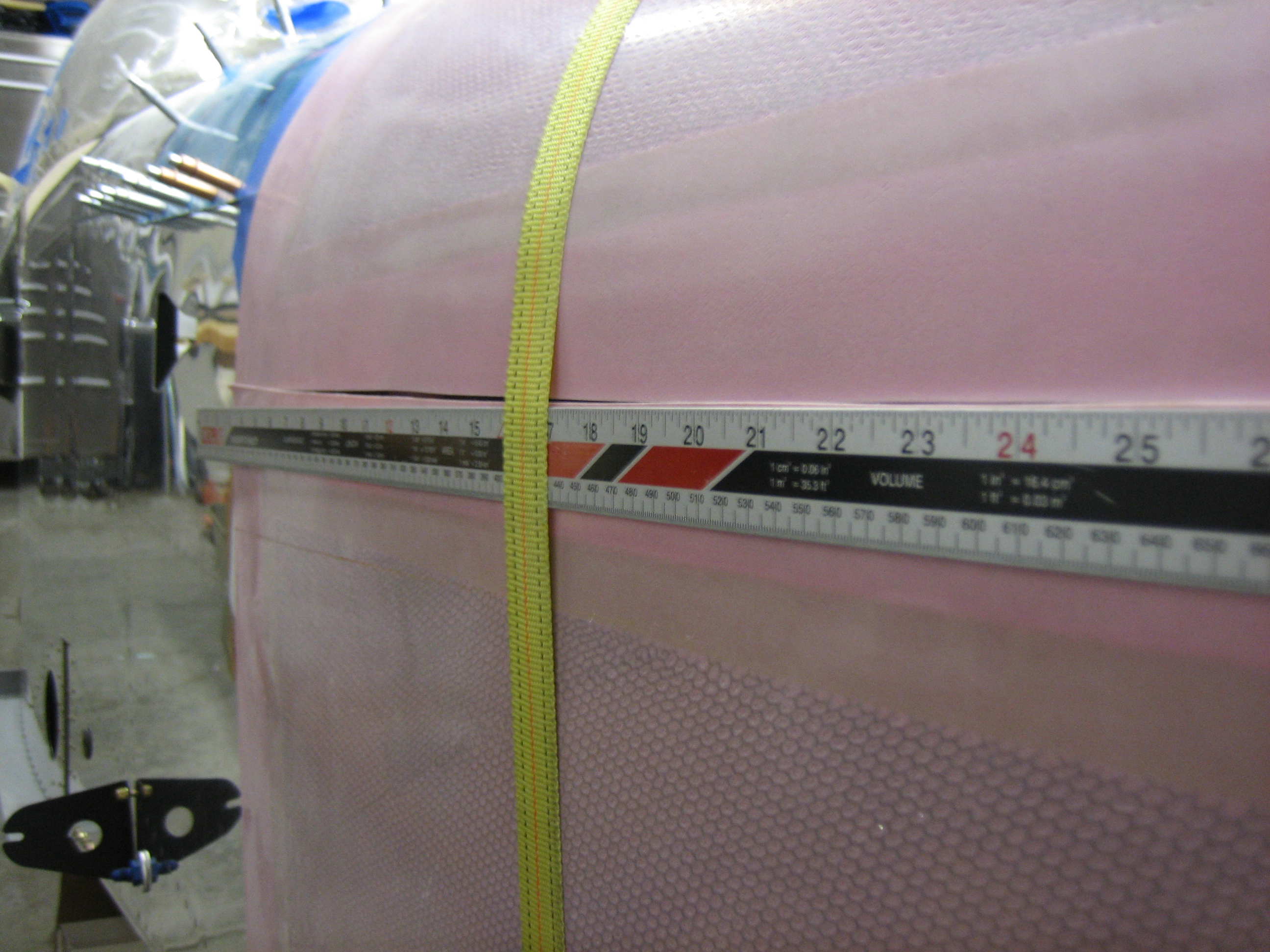
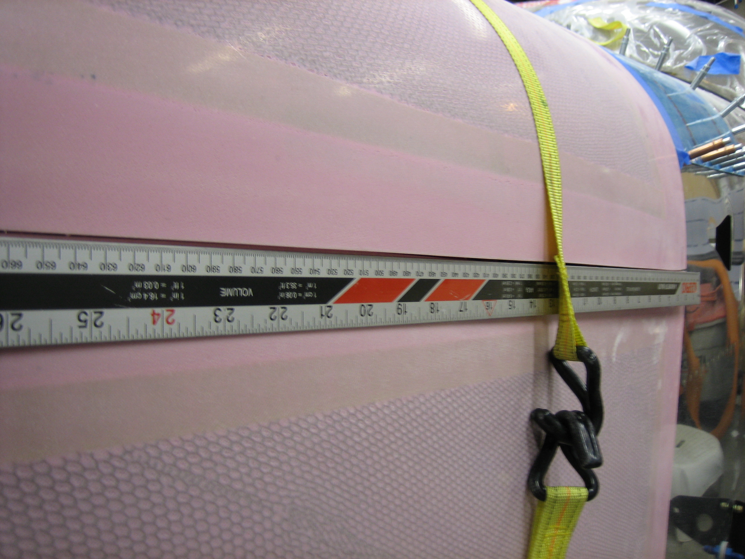
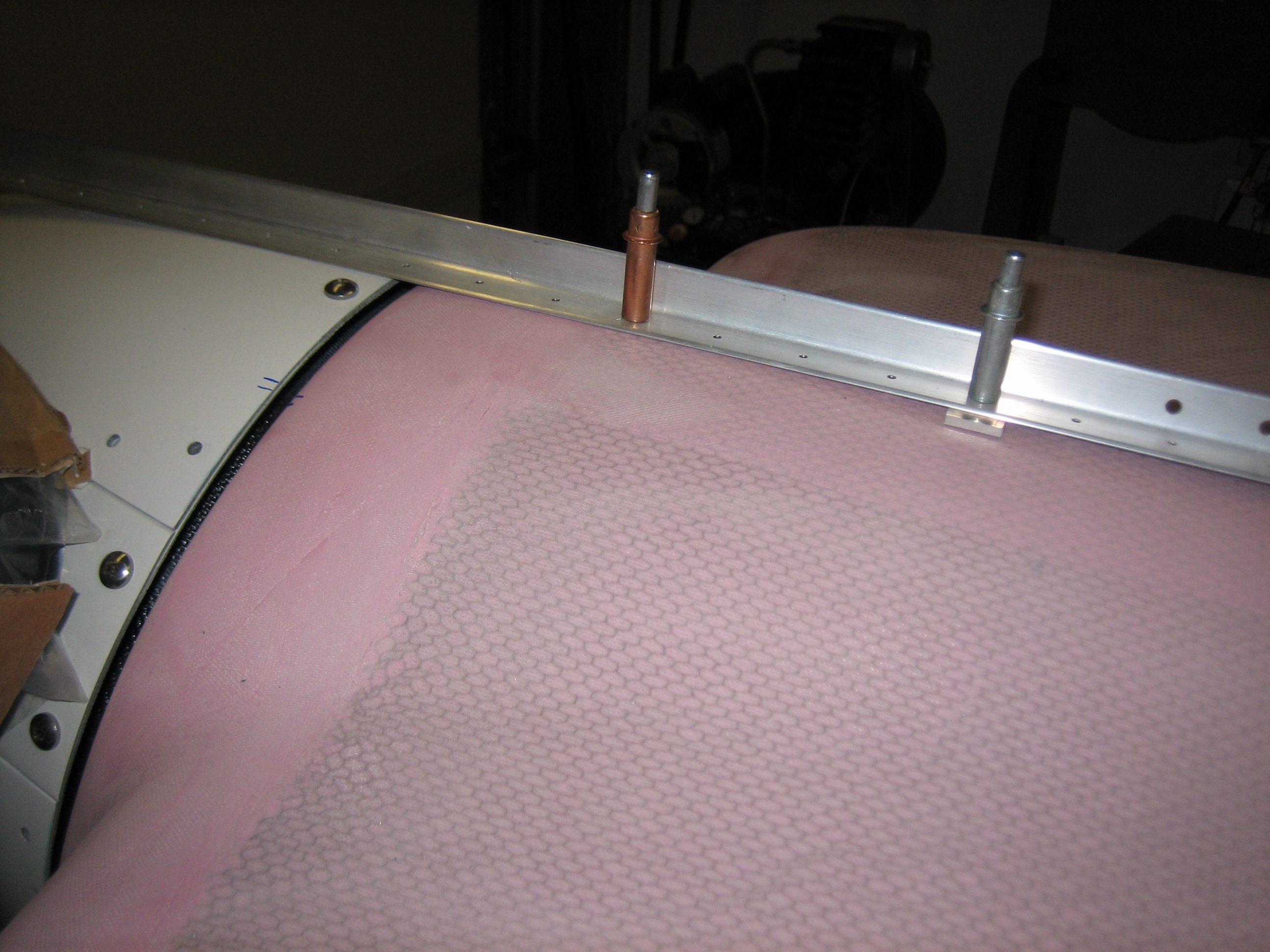
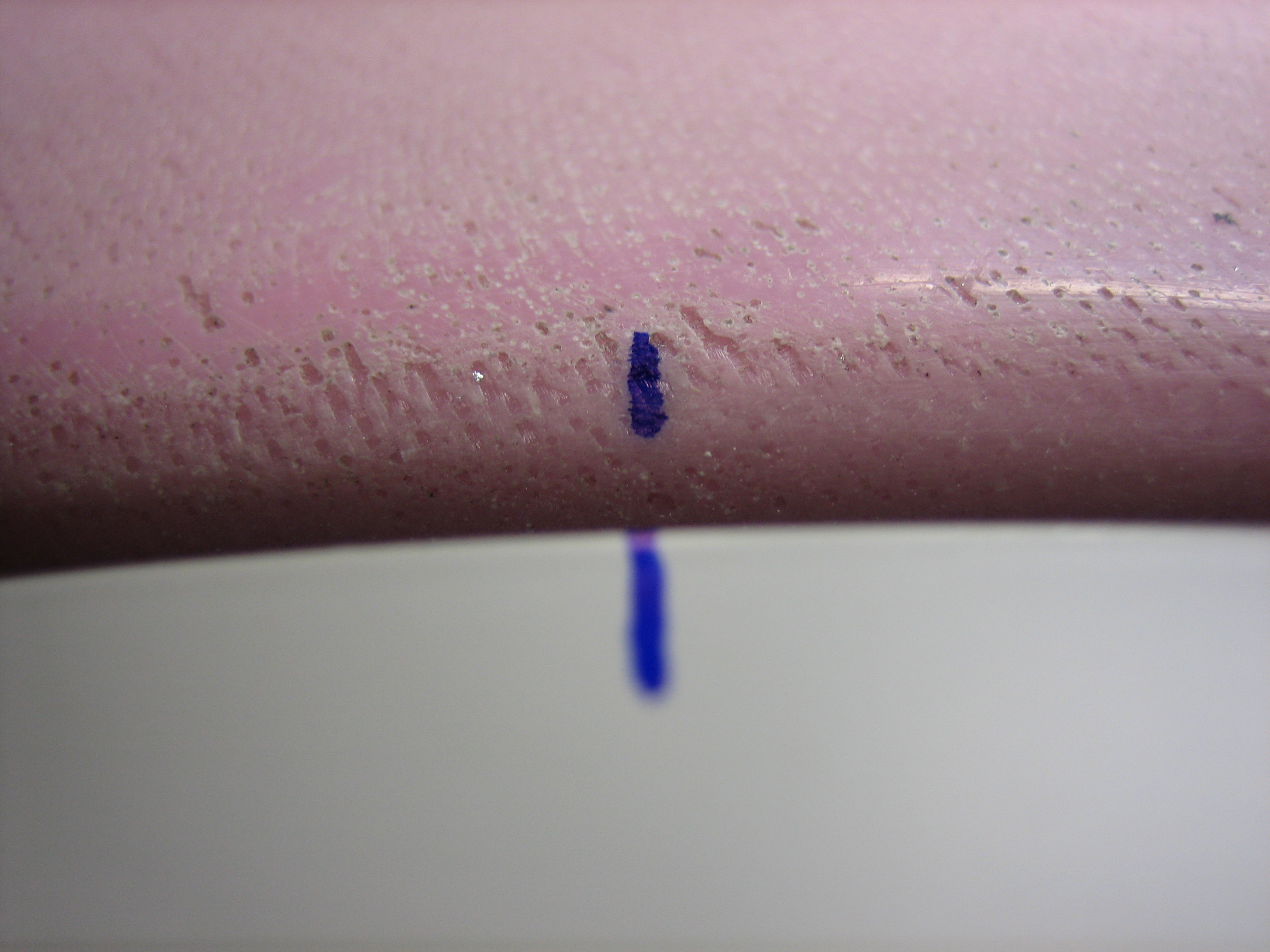
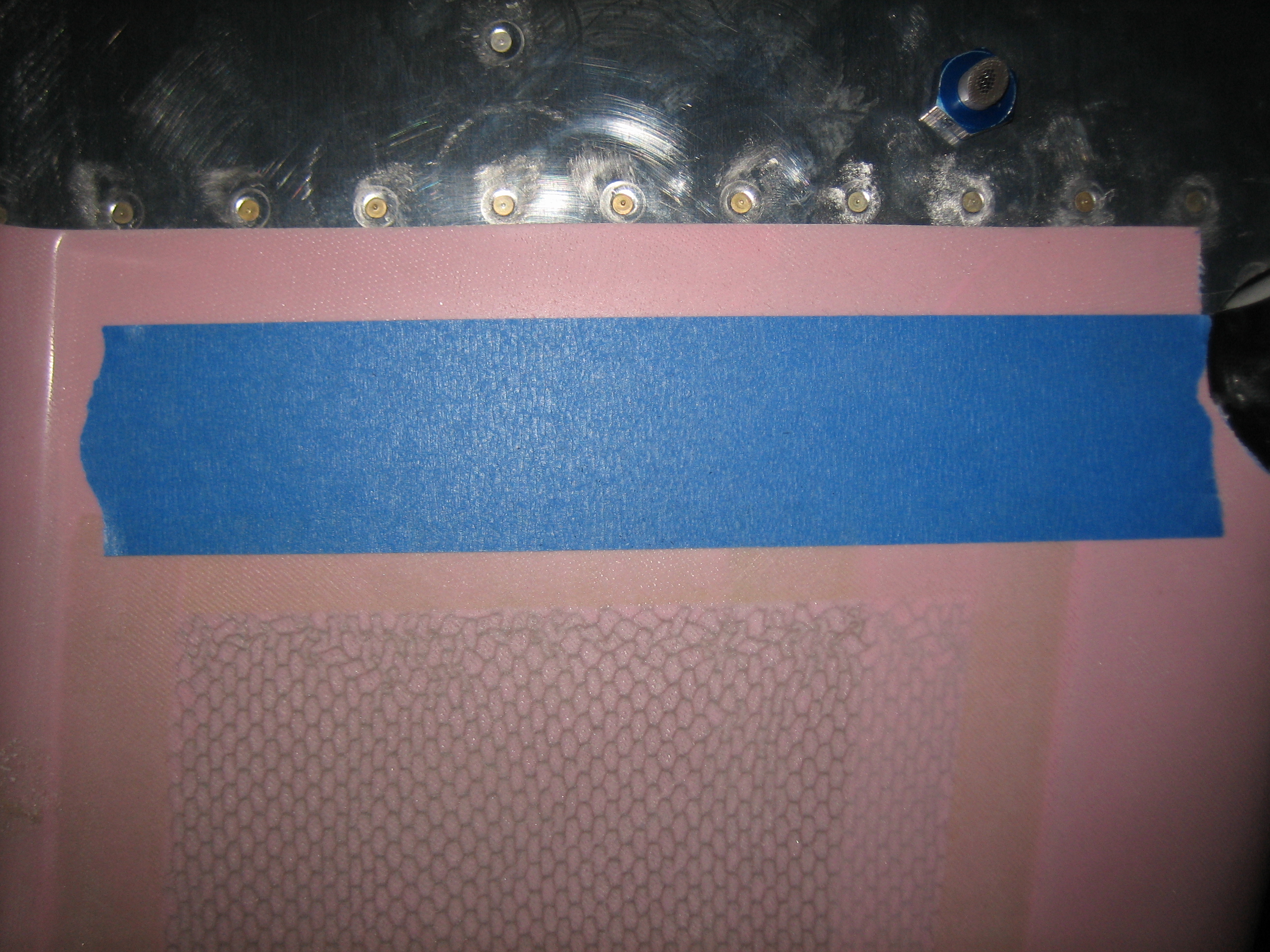
I cut out a 13″ diameter disk of hardboard to use in place of the spinner. I also cut a spacer that is the height of the firewall that is keeping the aft edges of the cowl the right distance apart. Even with the joint pulled tight and the flange around the disk as narrow as possible (without looking out of round), there are still small gaps on the outside edges. I’ll end up having to use some flox to make these joints tight. I also laid a straight edge across the center to see how straight all of the joints are. They’re ok right now, but I’ll need to sand these with a long straight edge to get them perfectly even.