My buddy Andre stopped by today to give me a hand with the rear spar carry-through bulkhead. First up is to shoot the two rivets I couldn’t do easily yesterday. I didn’t get a picture of it yesterday, but I also riveted on the main spar uprights. A few of these rivets could be squeezed, but most needed to be shot and bucked. I’m definitely getting the hang of doing that solo.
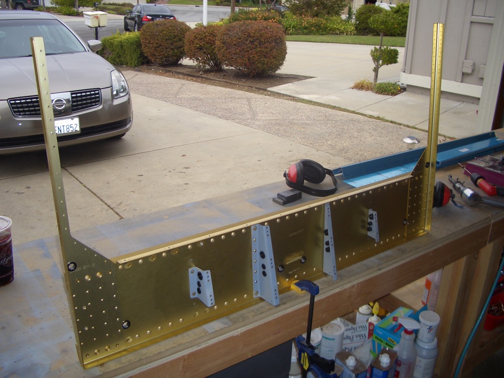
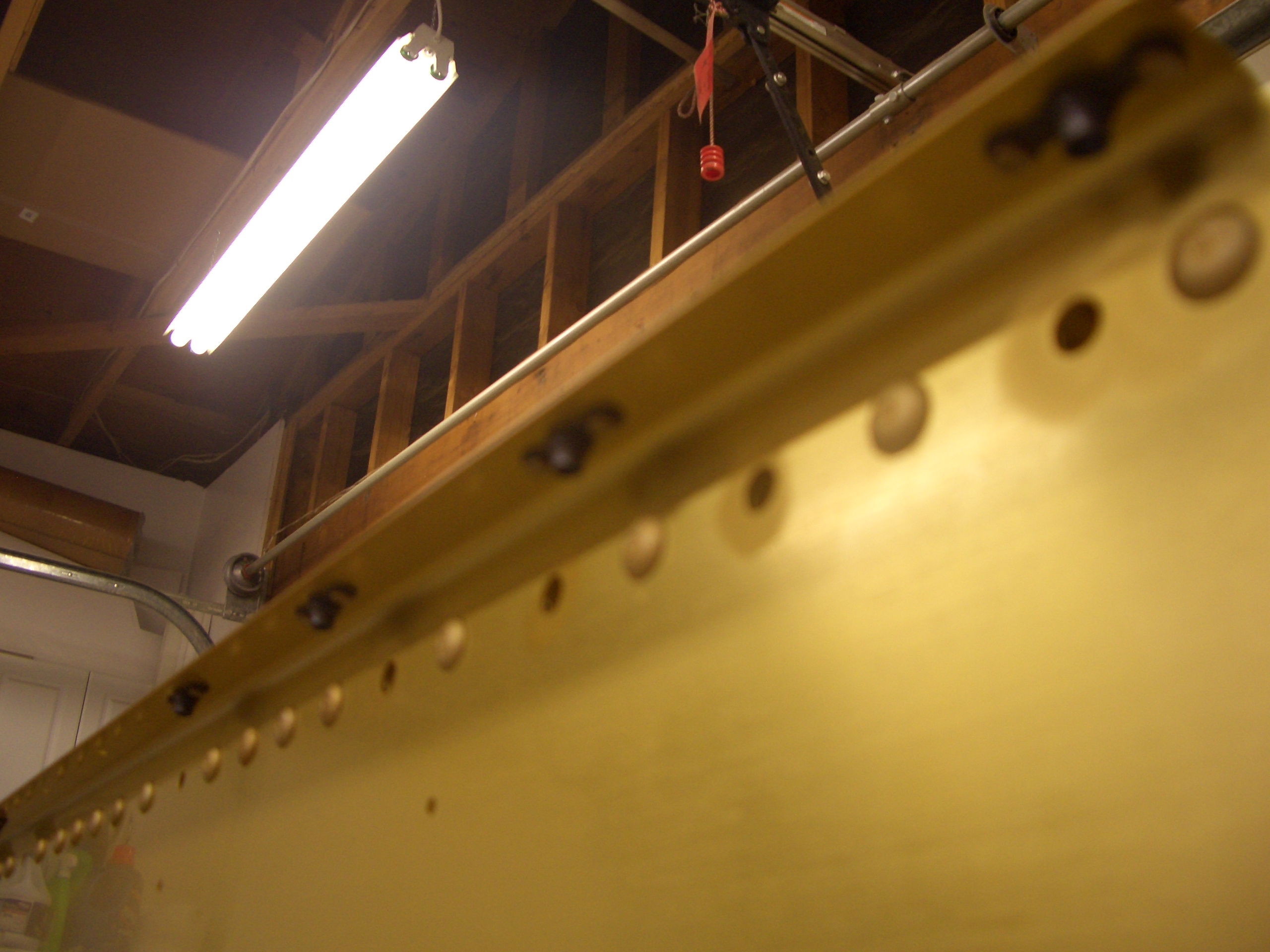
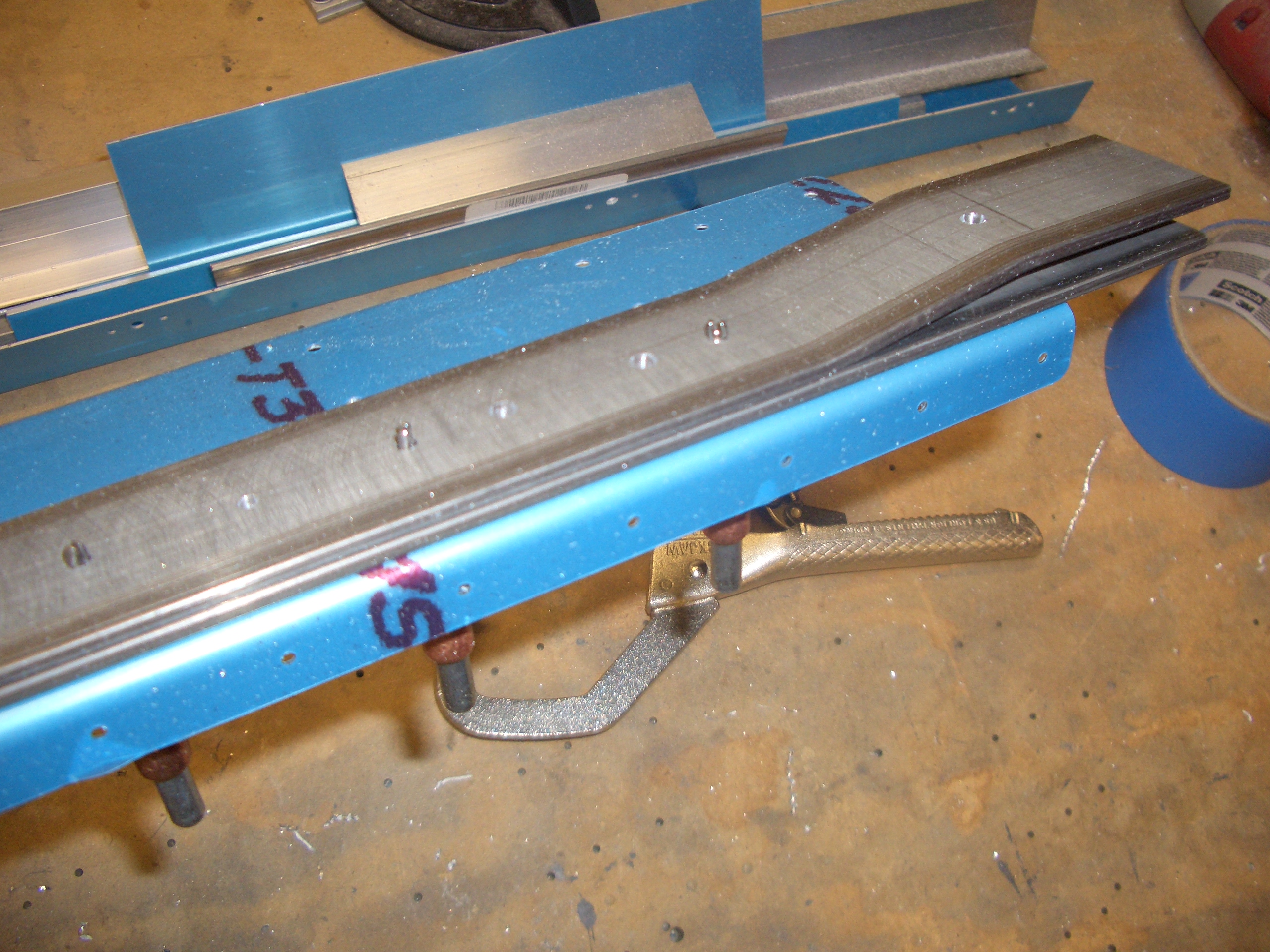
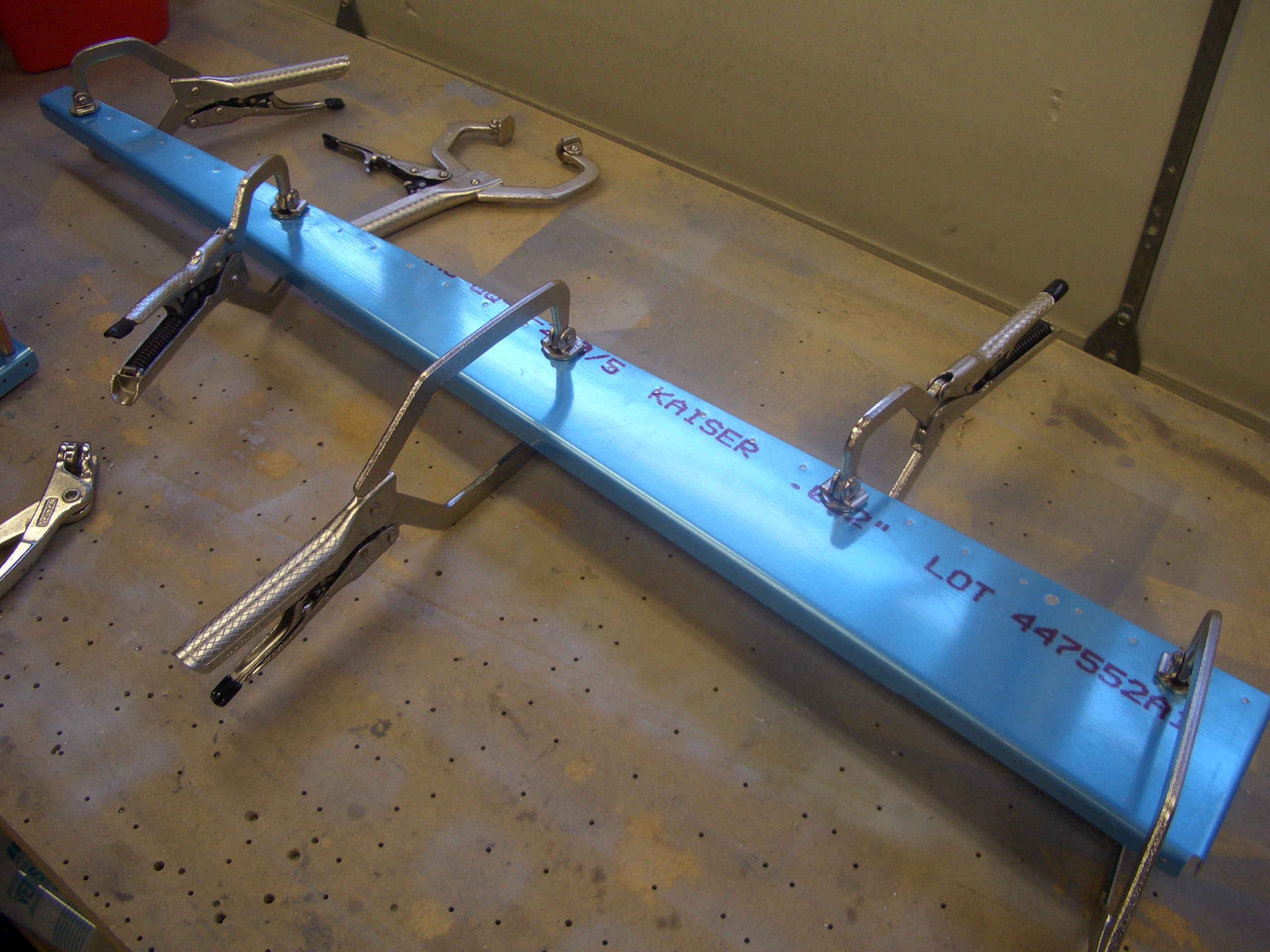
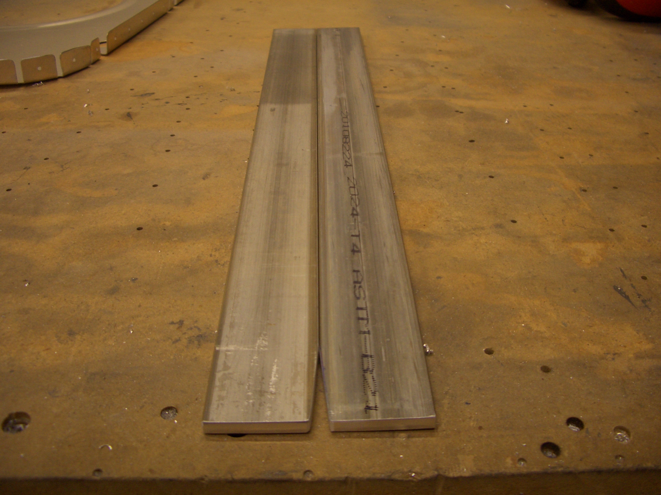
The rear spar bulkhead starts with a could of beefy pieces of 2024-T4 bar stock. The lower one in this picture runs all the way across the bulkhead and carries the major portion of the load. Shorter pieces of bar stock with a couple of bends in them are riveted to these to create a socket which will receive the rear wing spar.

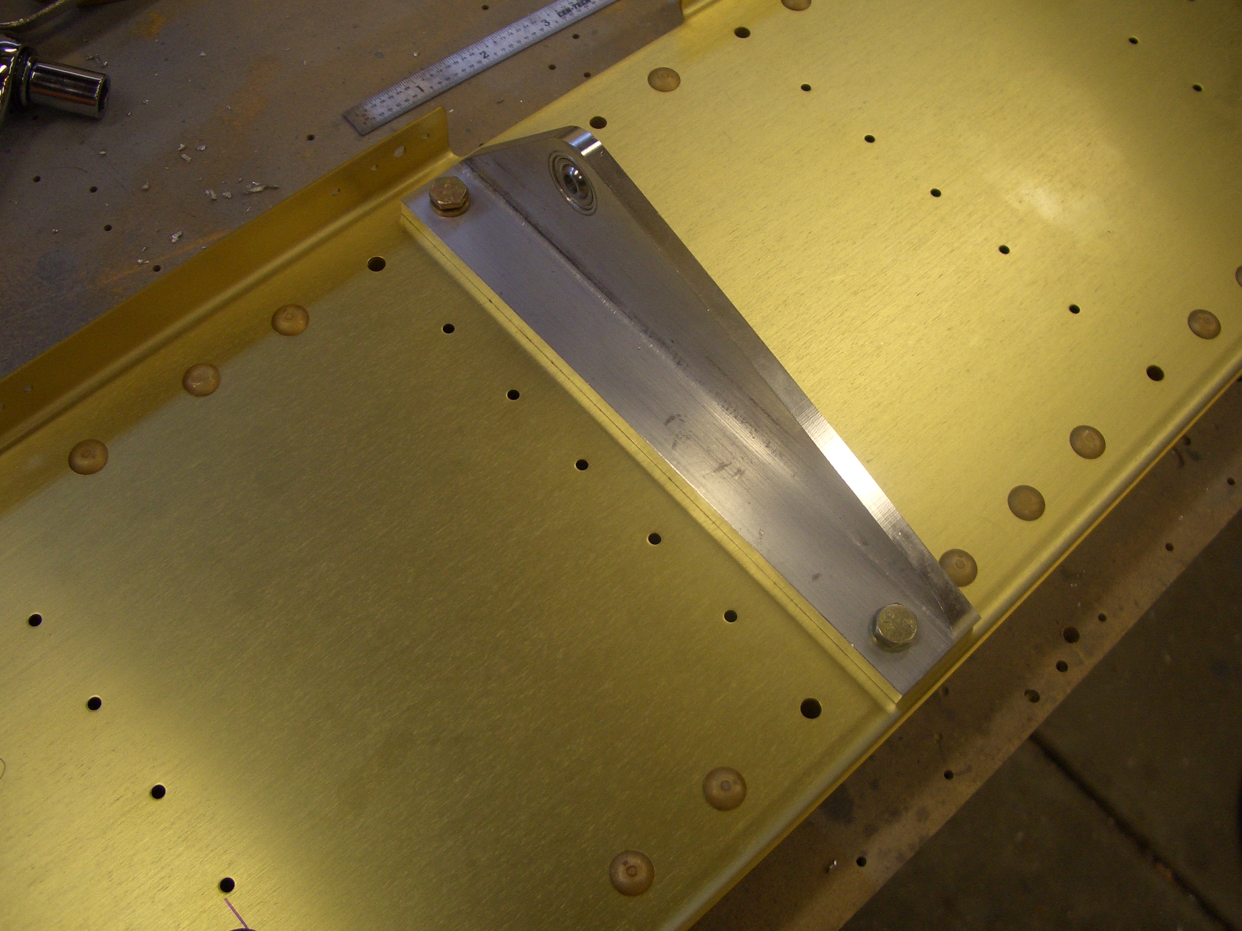
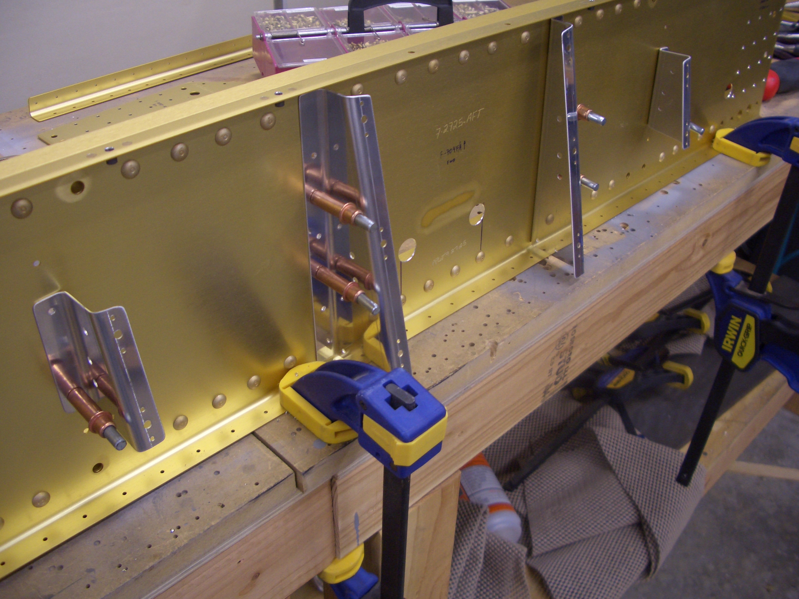
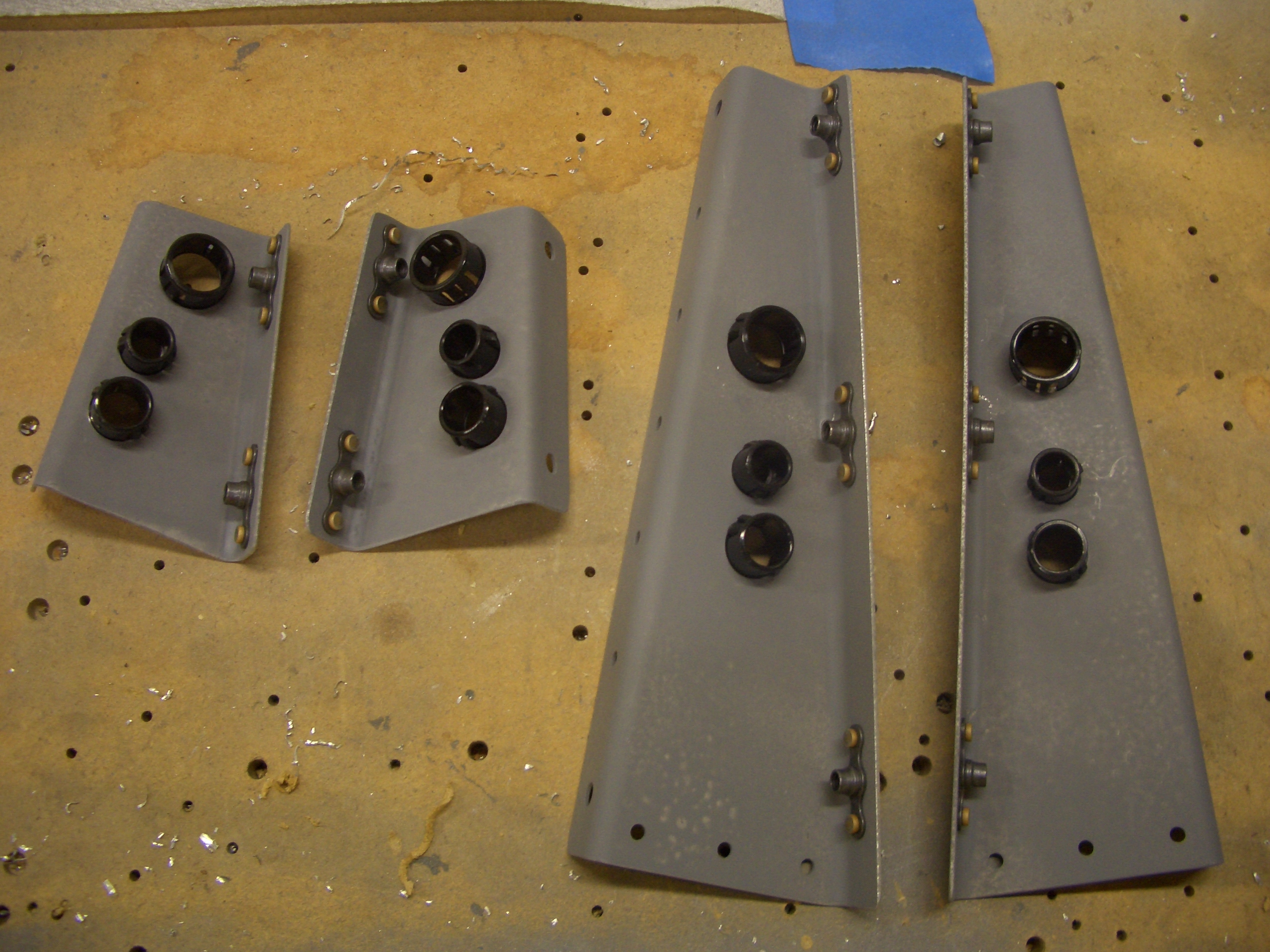
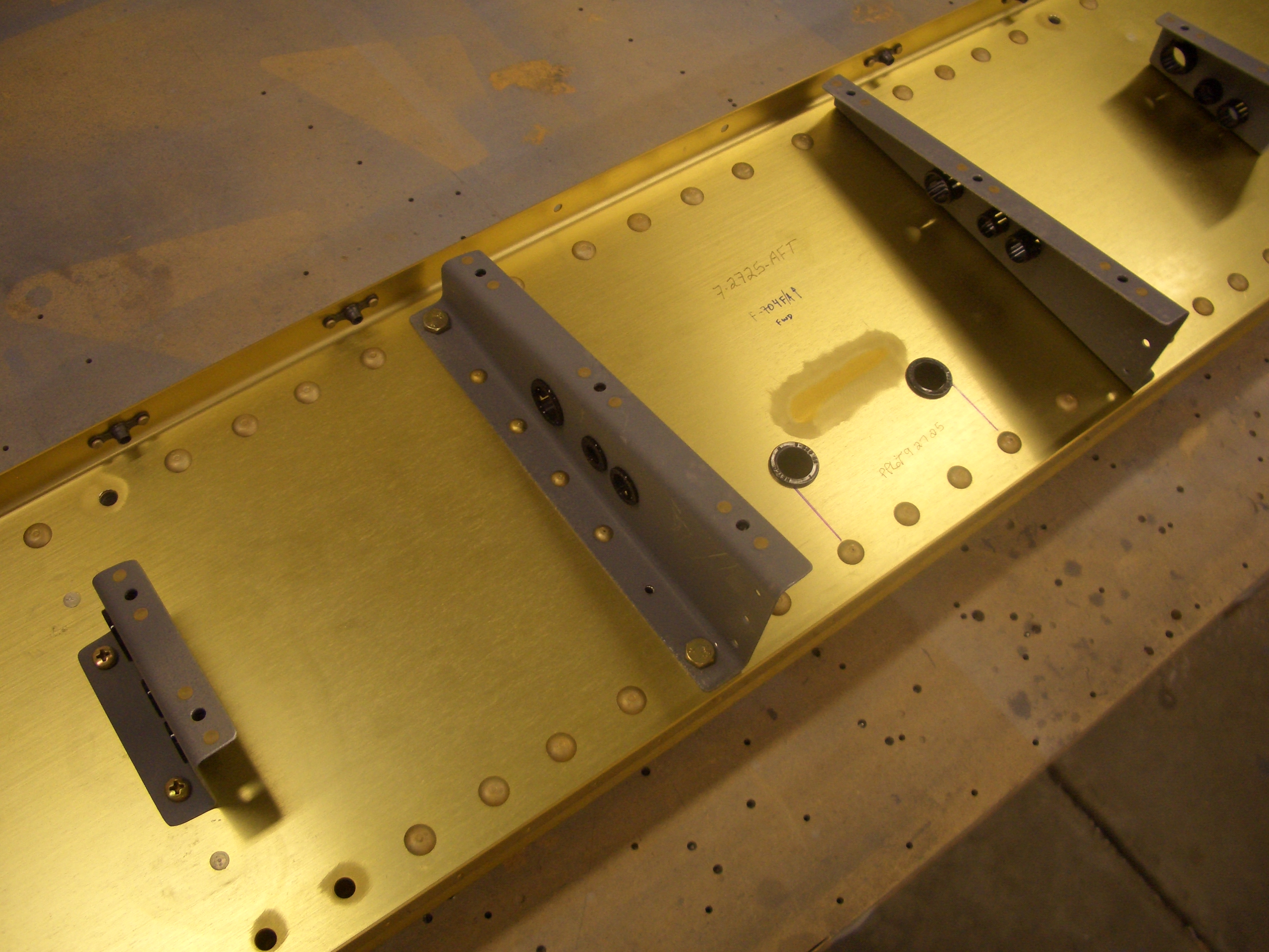
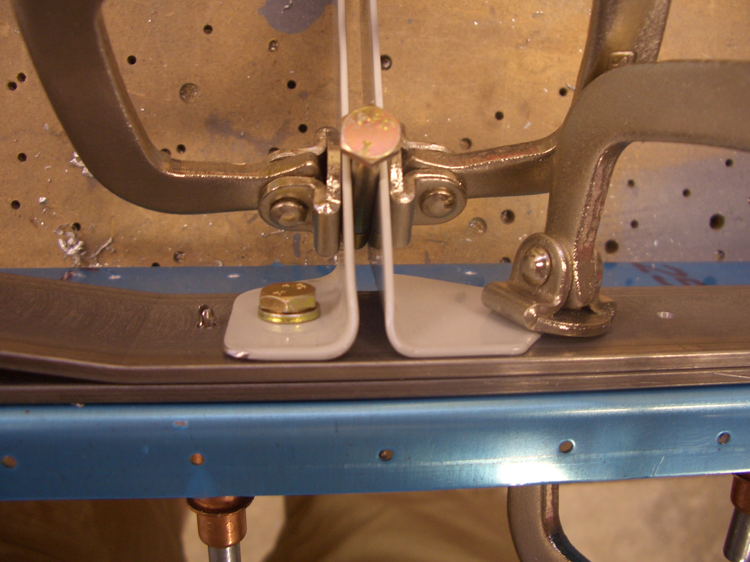
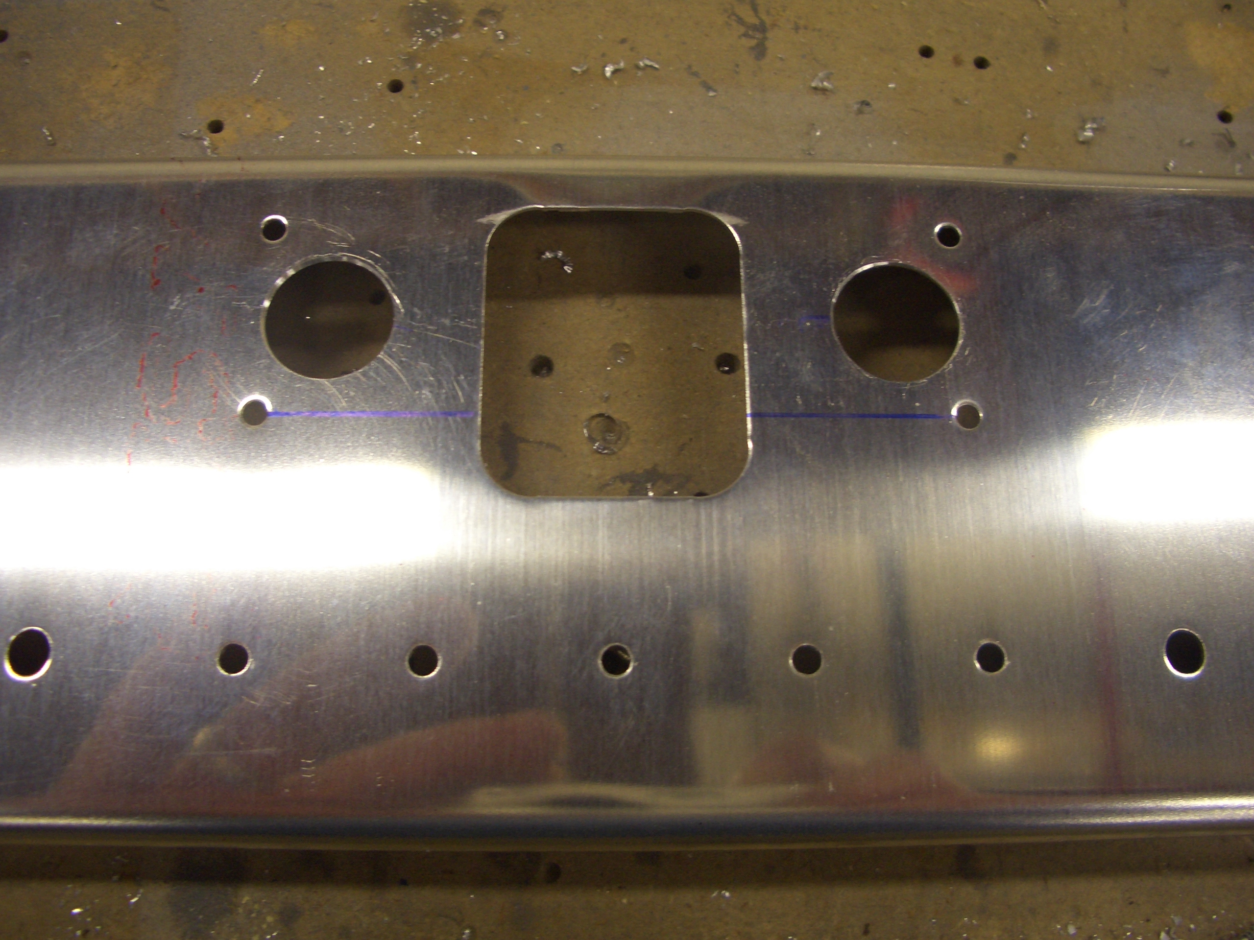
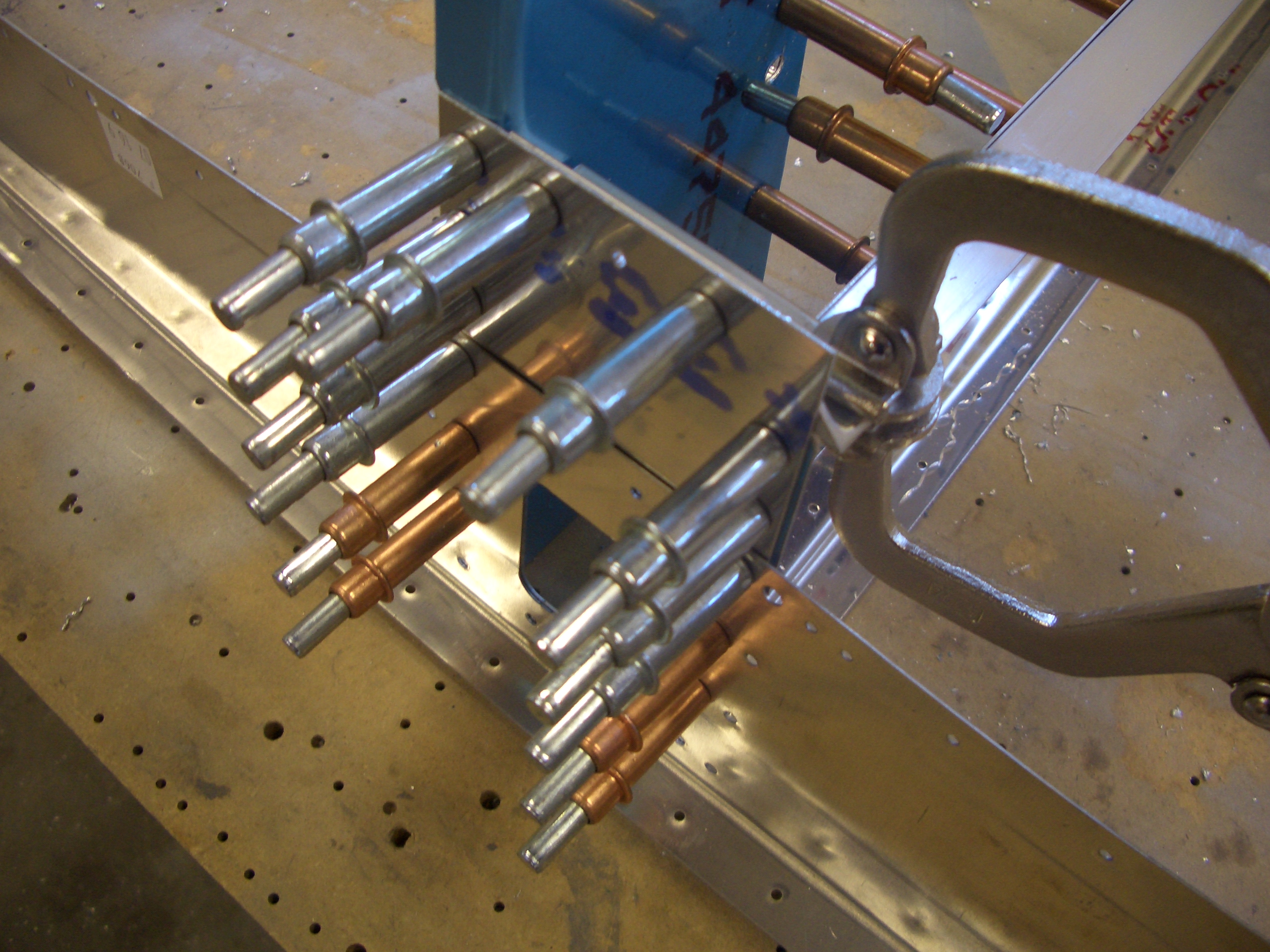
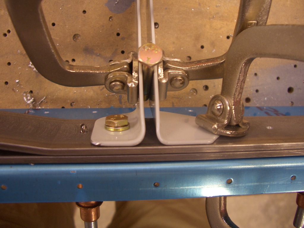
The lower seat belt attach points are drilled and bolted to the rear spar carry through structure. The technique here is to mark and drill one side that then clamp the other side in place with a 3/16″ spacer. An AN3 bolt is exactly 3/16″ thick, so clamping one of these between the anchors creates the perfect spacing. The holes in the top of the anchors (off the top of the picture) are held in alignment with an AN4 bolt. The other anchor can then be back drilled through the spar. You can also see here the outboard seatbelt attach points require the anchors to be cut to clear adjacent rivets. Here, the left anchor has been cut, but the right one is still full size.
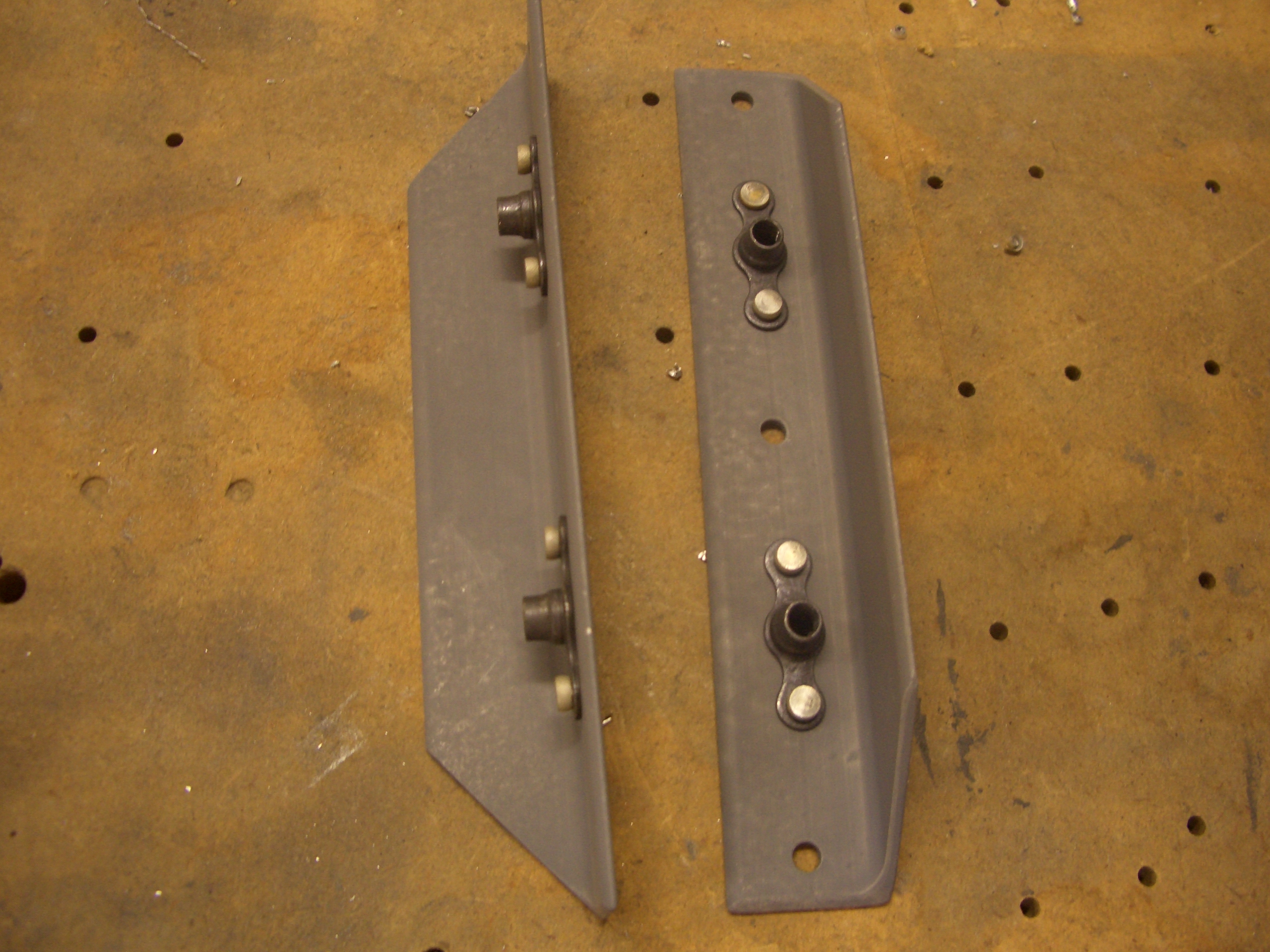
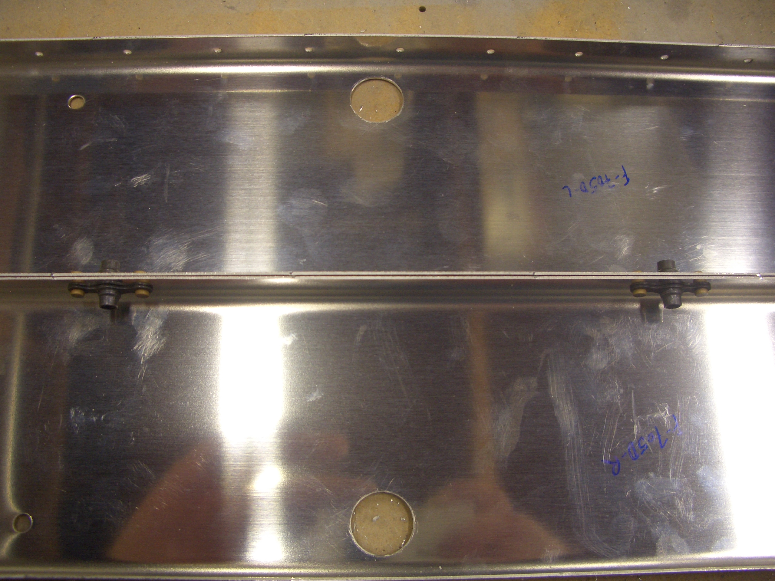
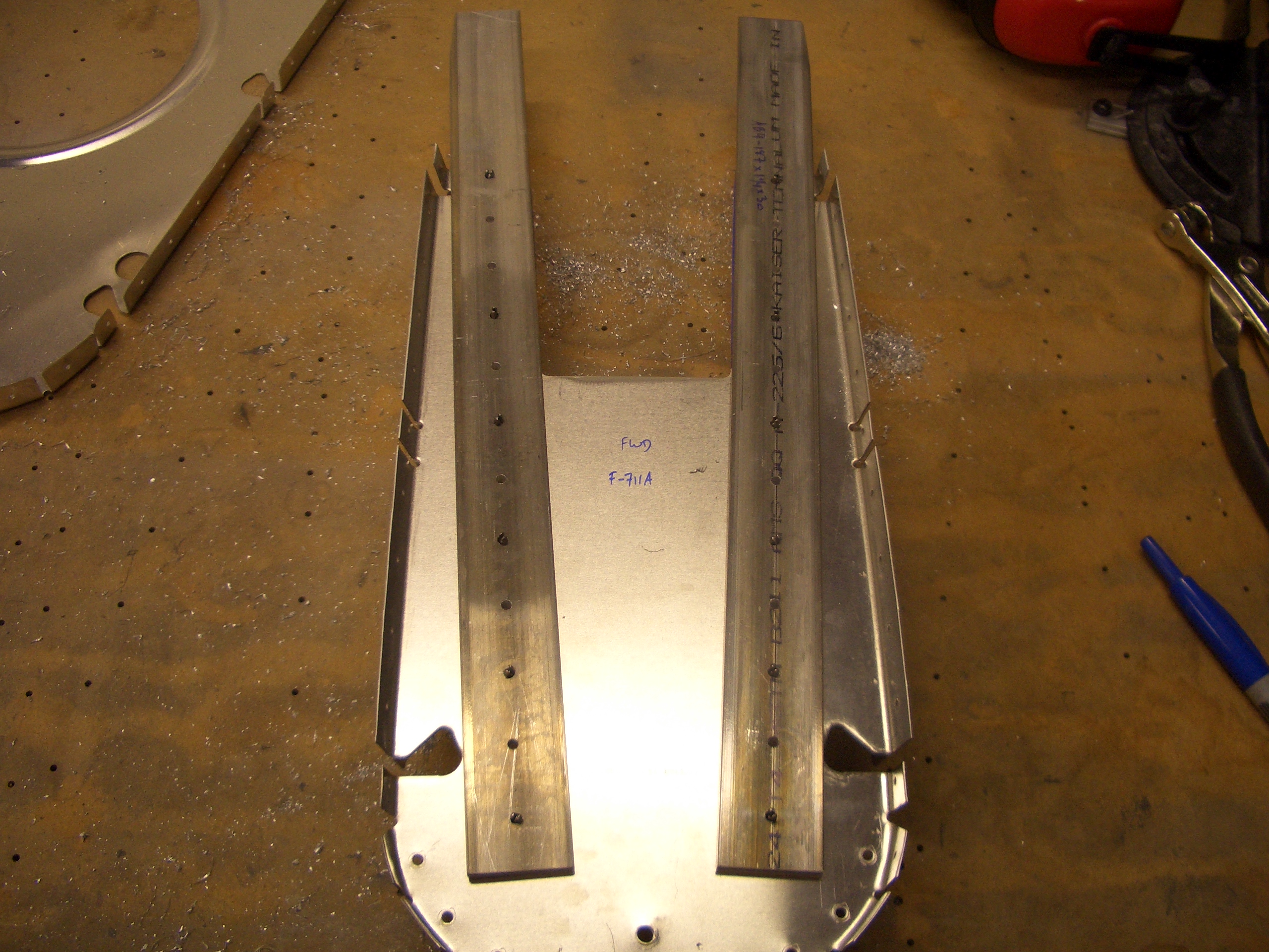
Here are all four seat belt attach points match drilled to the spar.

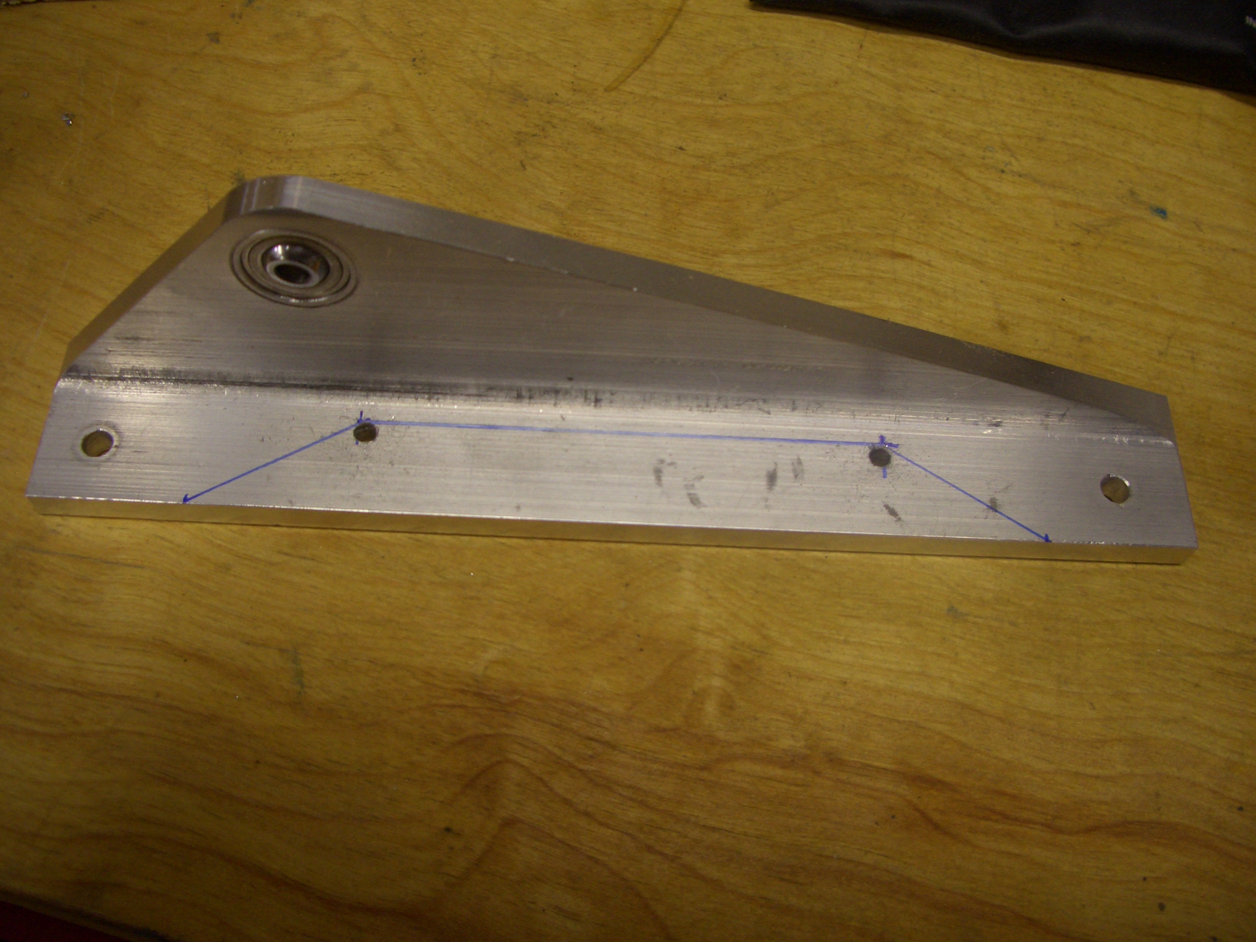
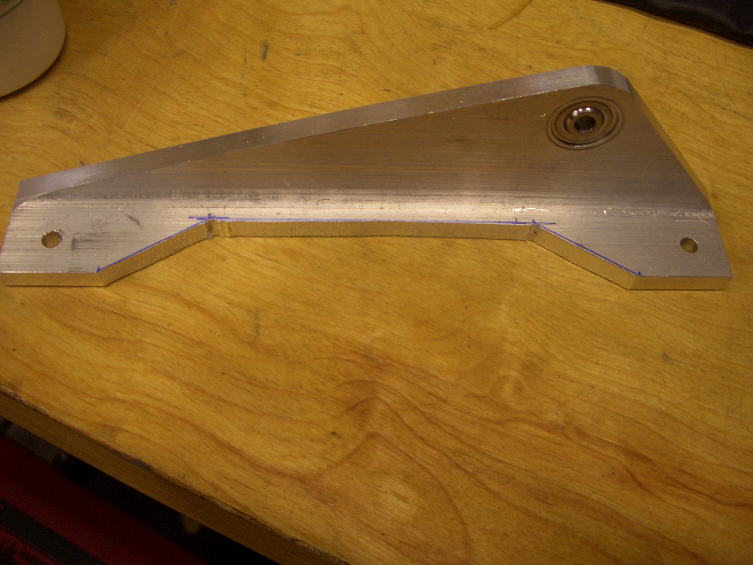
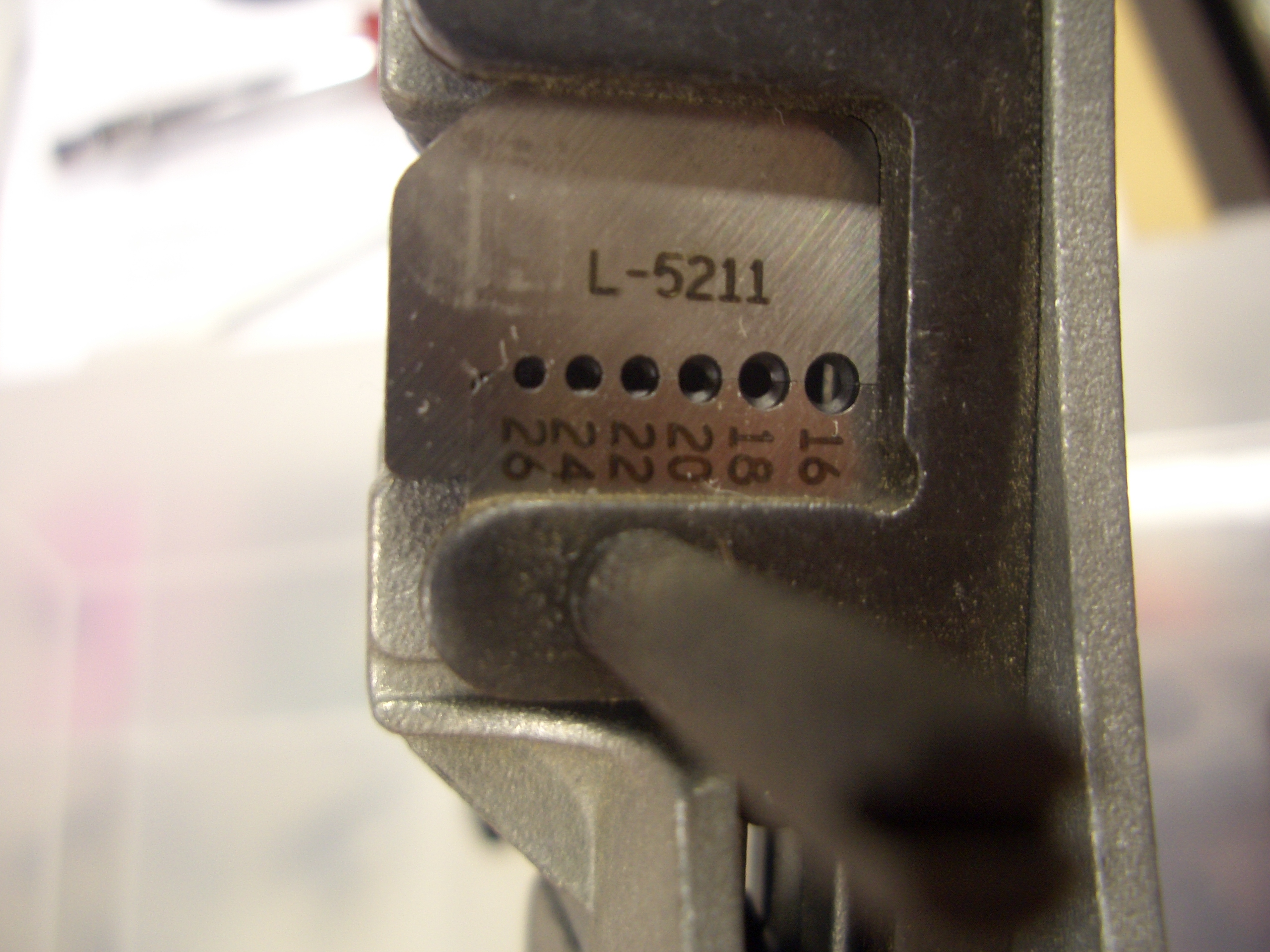
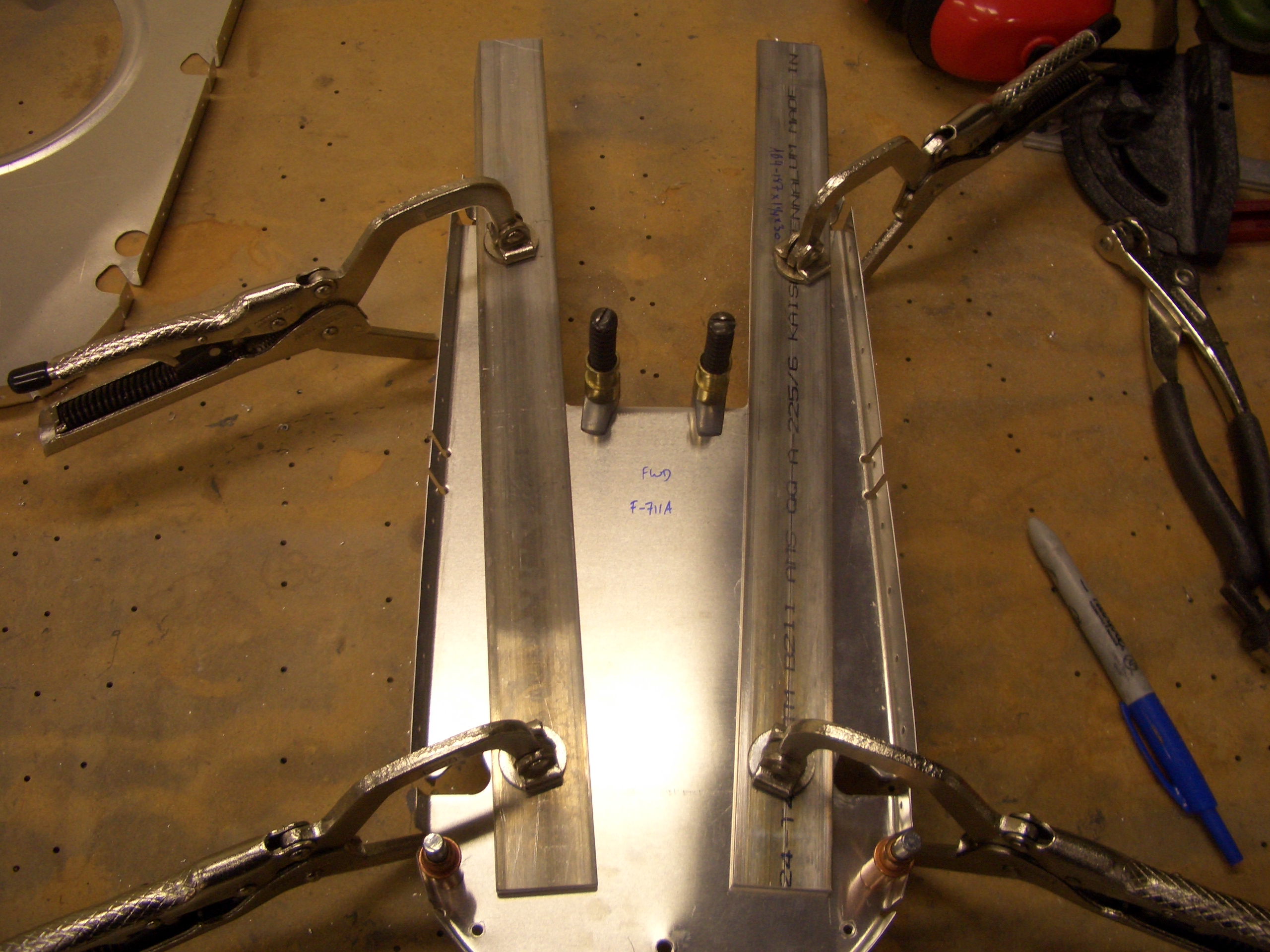
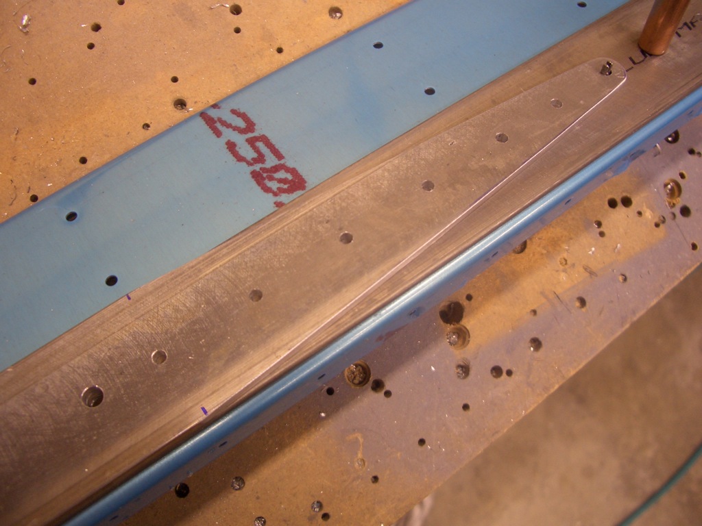
The shorter spar bars are tapered for weight reduction. You need to make sure that the last rivet has 1/4″ edge distance all around the radius. By positioning this end first, I could easily ensure that.
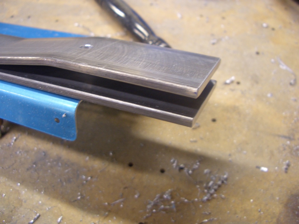
Then the other end can be cut flush with the long spar bar.
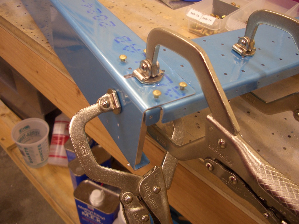
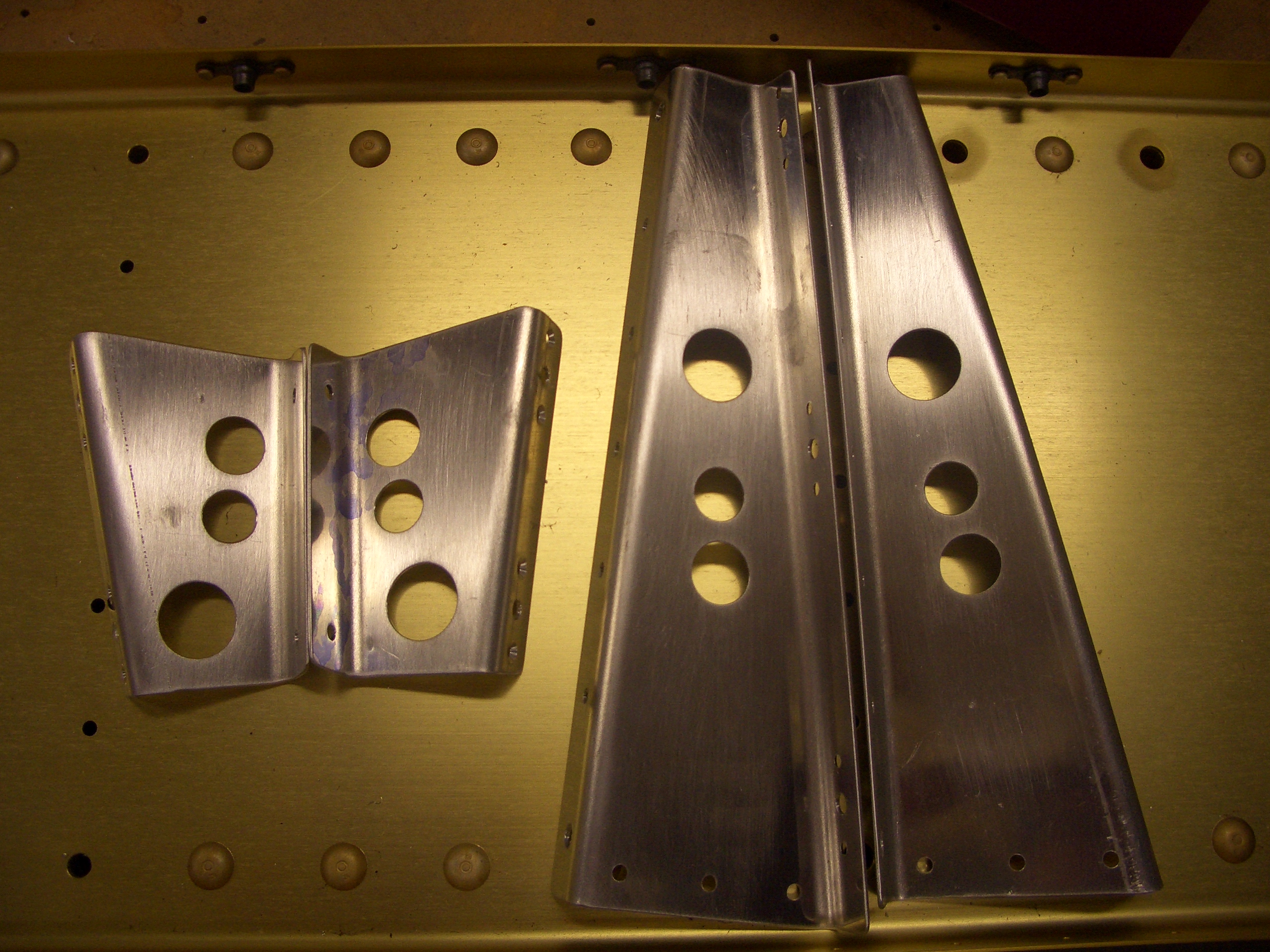
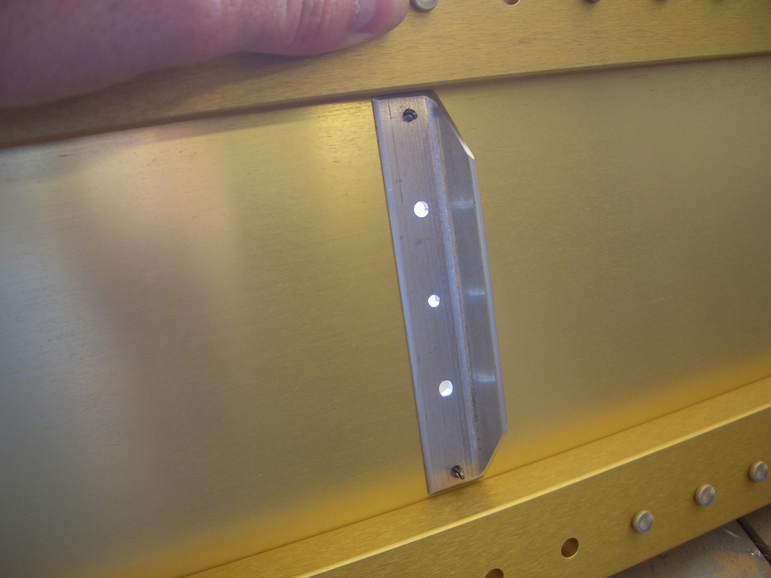
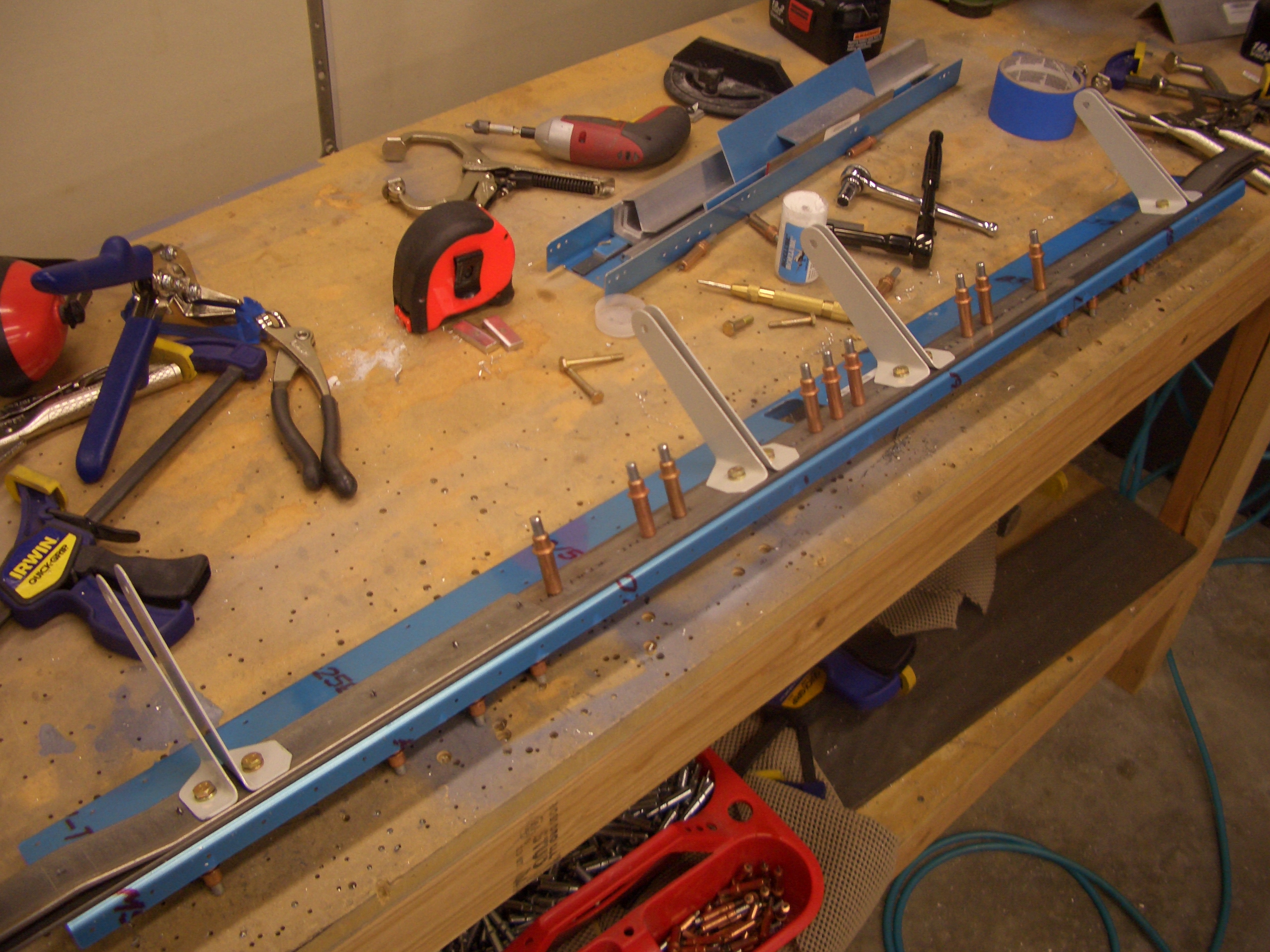
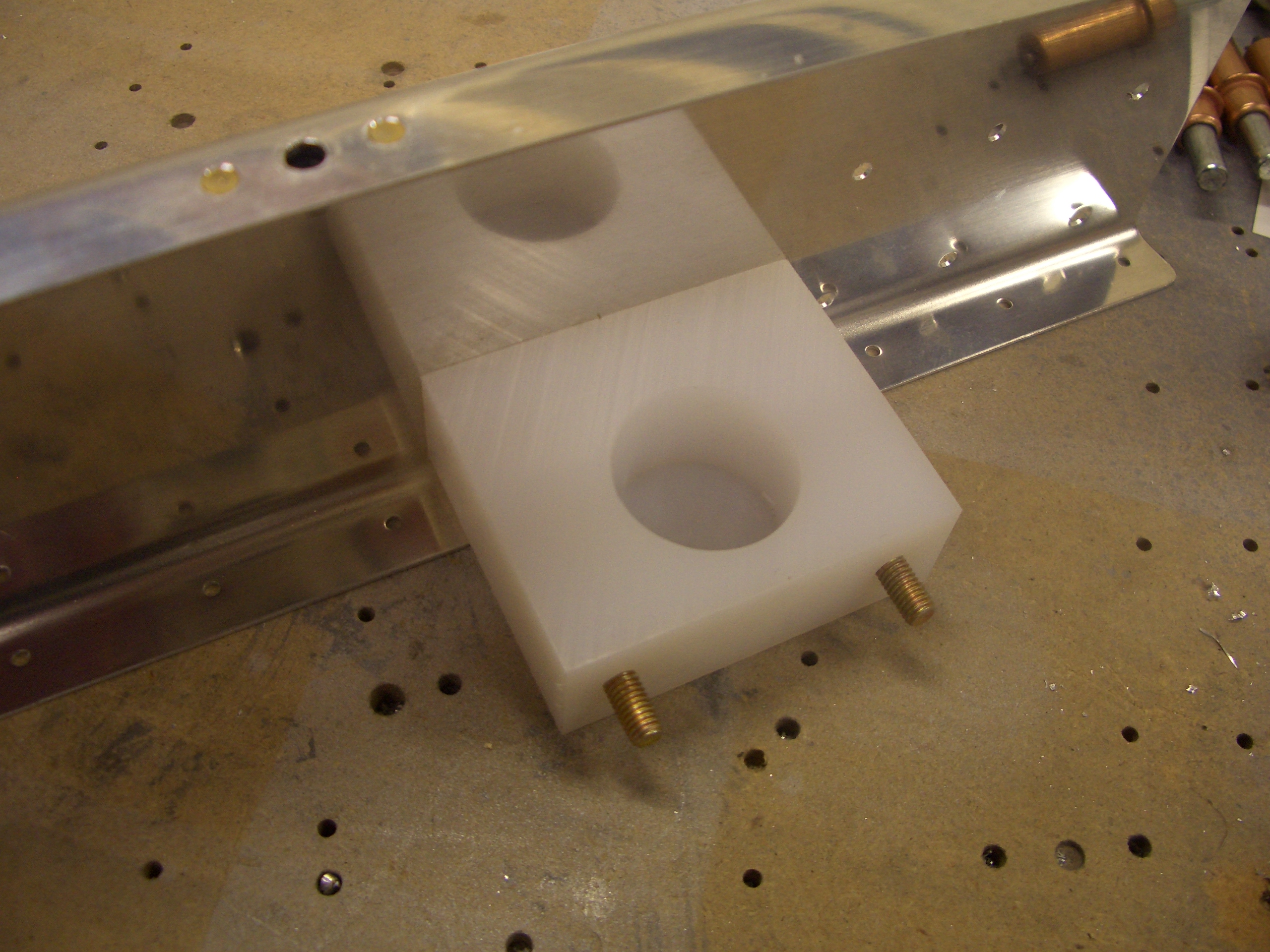
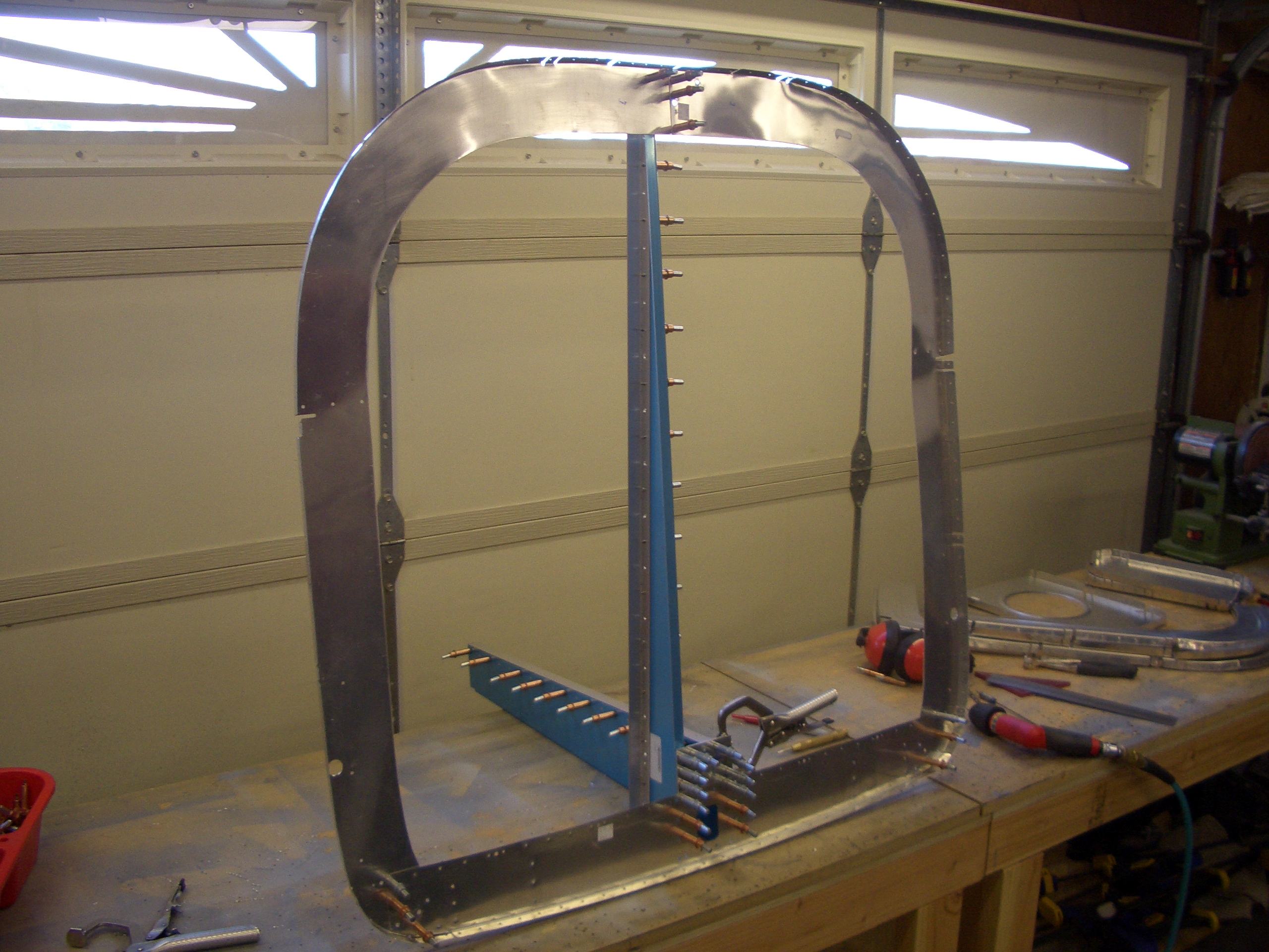
While I was working on the rear spar, Andre fabricated the upper angles that will receive the canopy latch pins.

The angles fit behind the upper portion of this bulkhead. I drilled the four corner holes so that I could use rivets to keep the three prepunched pieces in alignment. The angle could then be clamped in position and the holes match drilled. I’ve said it before, but these self-adjusting clamps absolutely rock.