No pictures today. I spent several hours deburring fuselage bulkheads. I still have a fair amount to do before priming.
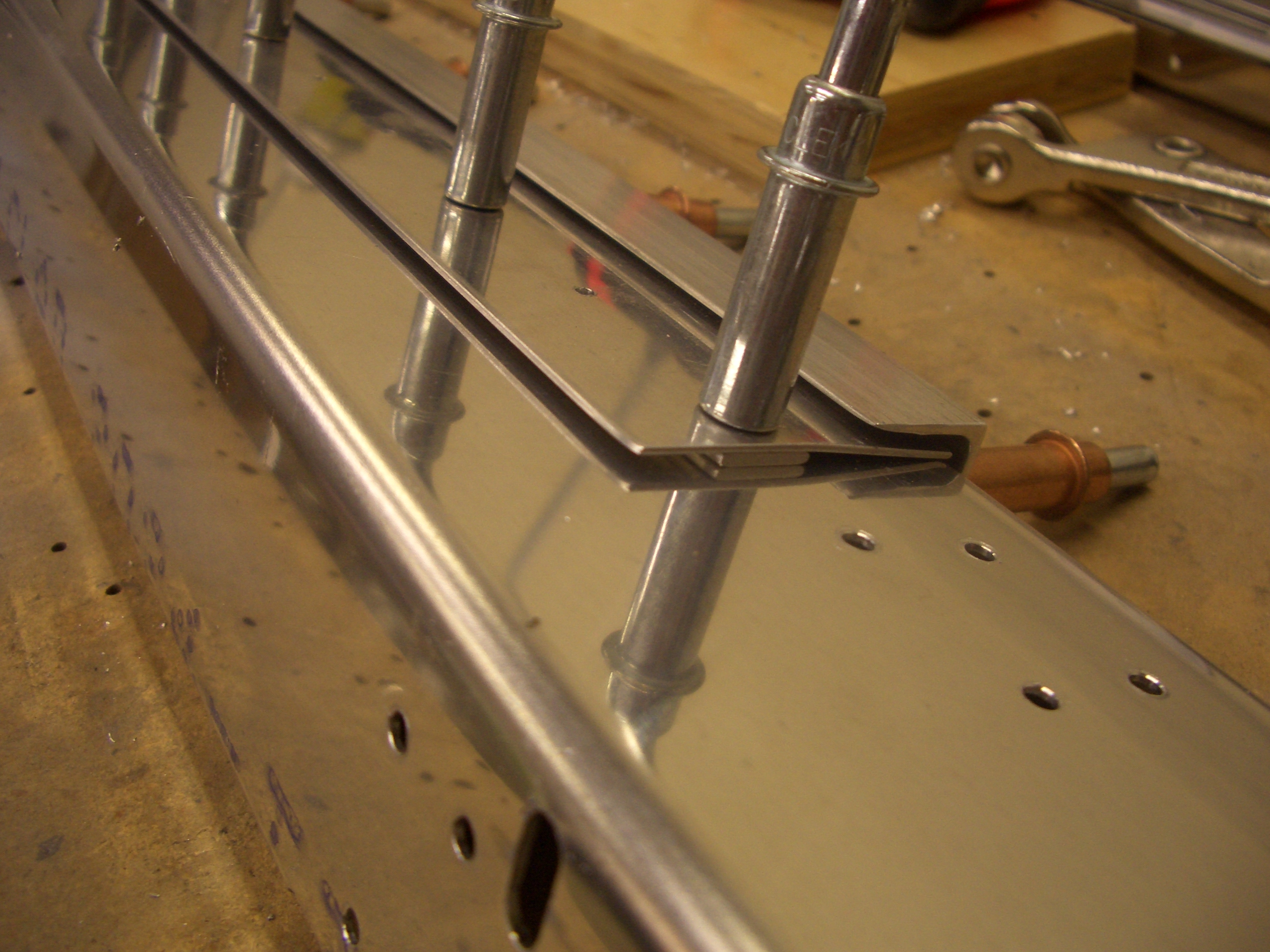
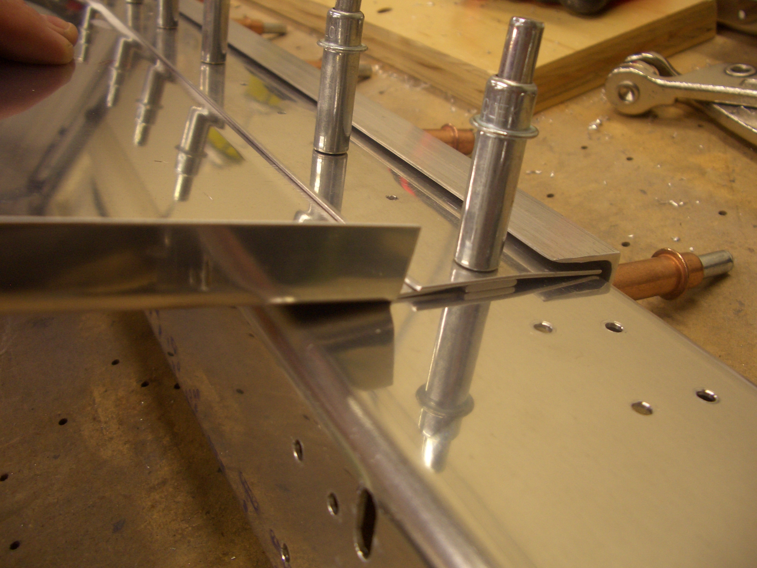
Bent Upper Seat Adjustment
A couple of pieces of the upper seat adjustment mechanism needs to be bent to 4º. I tried this without a brake and the bend was pretty poor. I took advantage of the black friday sale at Harbor Freight to pick up this brake and made perfect bends in just a couple of minutes.
Upper Seat Back Adjustment
I drilled the upper seat back adjustment pieces. None of these pieces have any layout holes, so everything has to be measured and drilled.
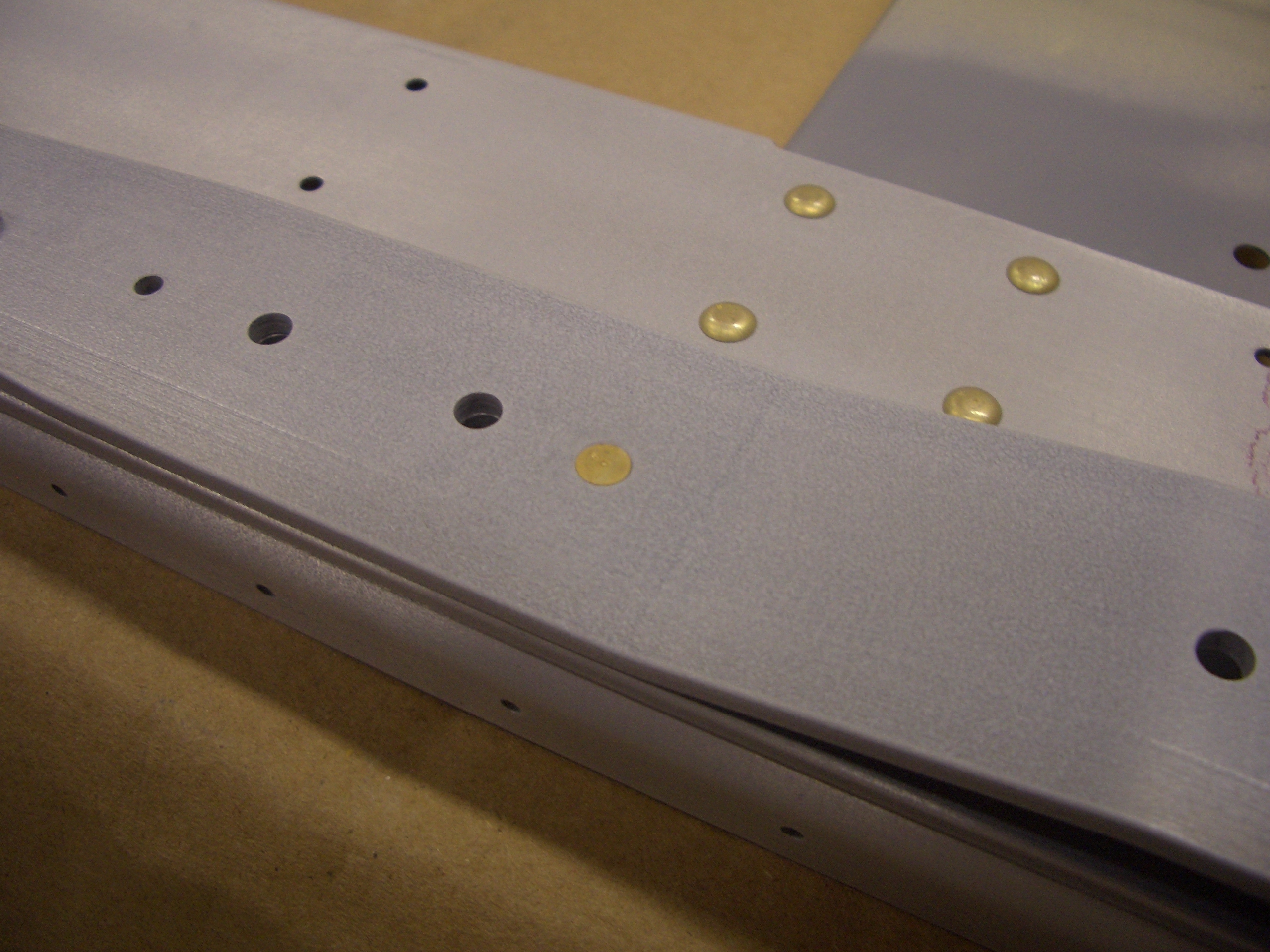
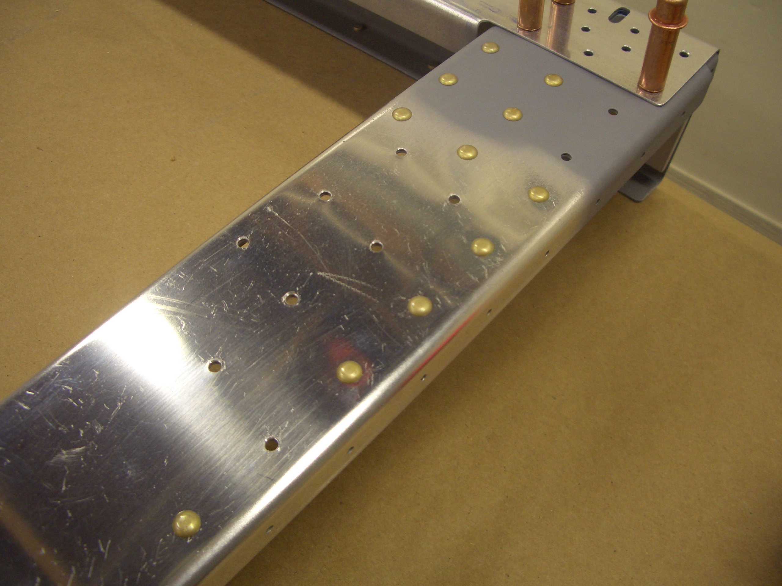
Prepped, Primed and Riveted Bulkheads
The bulkheads have a bunch of separate flanges because of the tight radius of some of the curves. Some emery cloth cut into 1/4″ wide strips works pretty sell when used like dental floss.

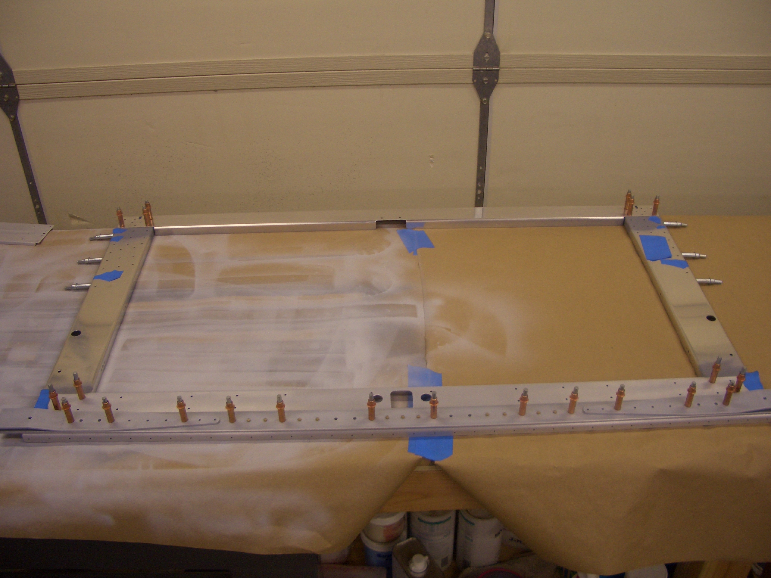
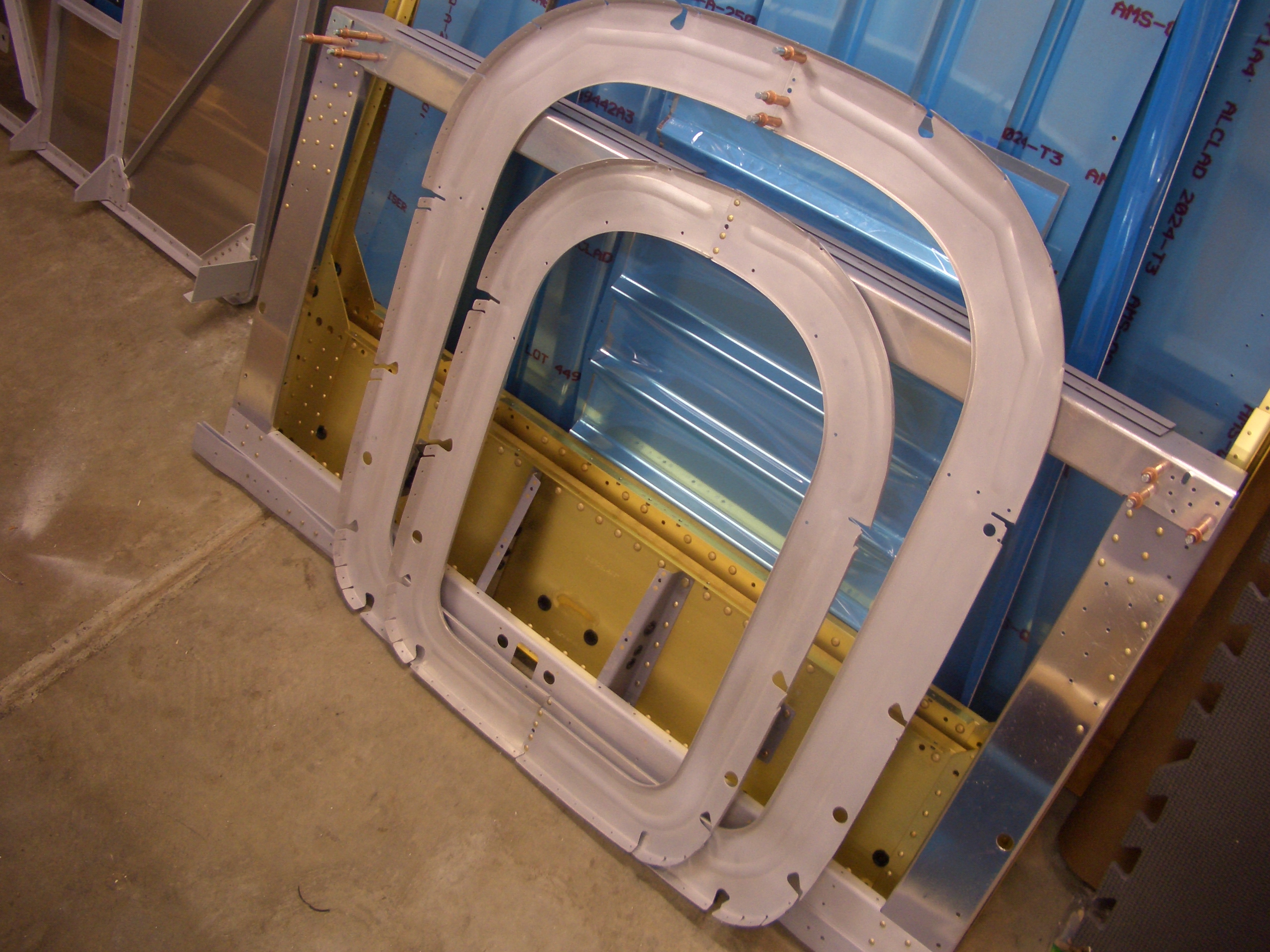
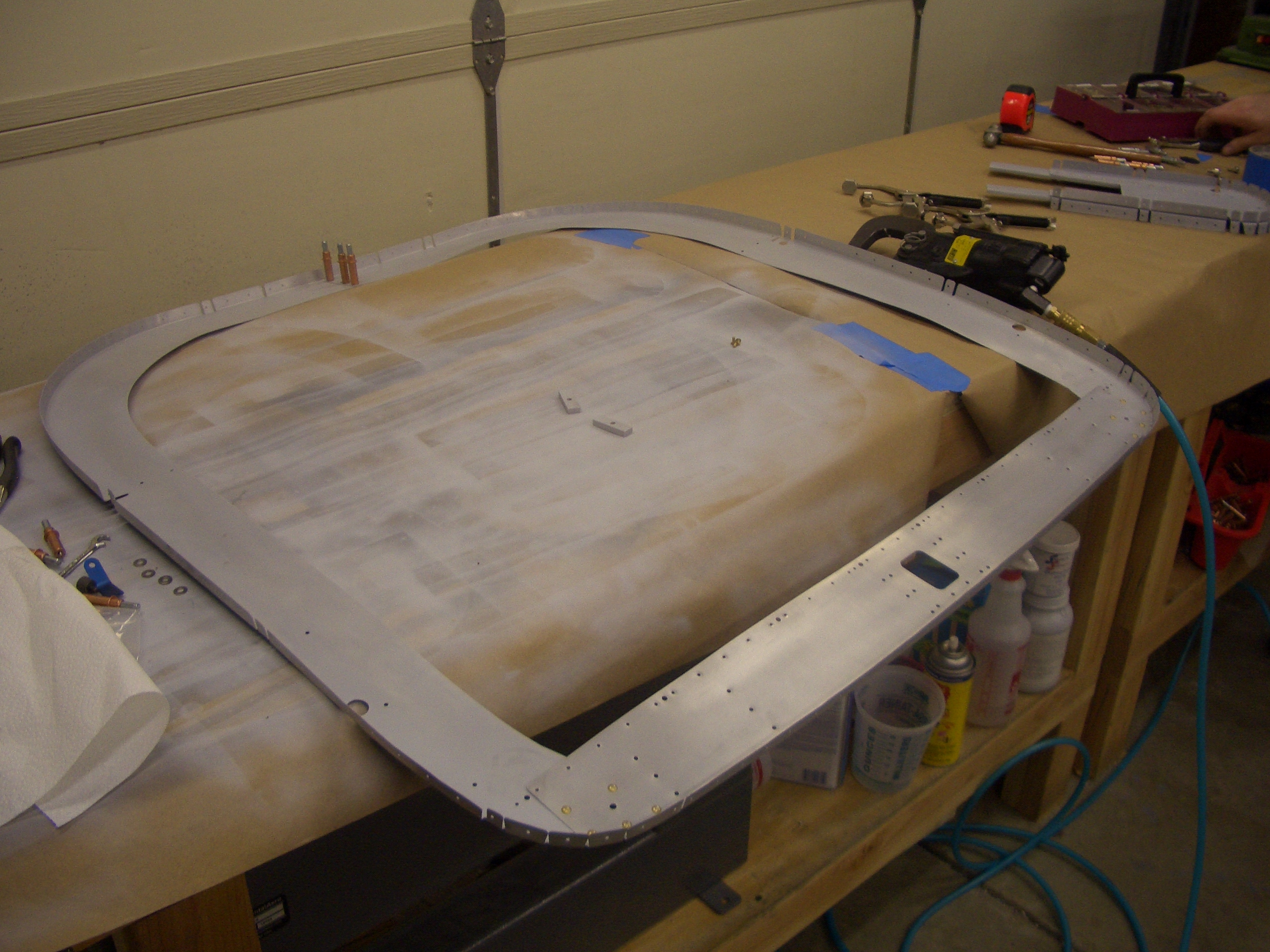
After a lot of sanding, cleaning and priming, the bulkheads are starting to go together. Here, the F-705 bulkhead is clecoed together. Double check that this bulkhead is square before riveting since the clecos allow some play in these pieces. I could change the diagonal measurement as much as 1/4″ by racking these pieces from side to side. After assuring that everything is square, this can be riveted together. The blue tape signifies the holes that need to be left open right now since they will be riveted together with other parts of the structure at a later time.
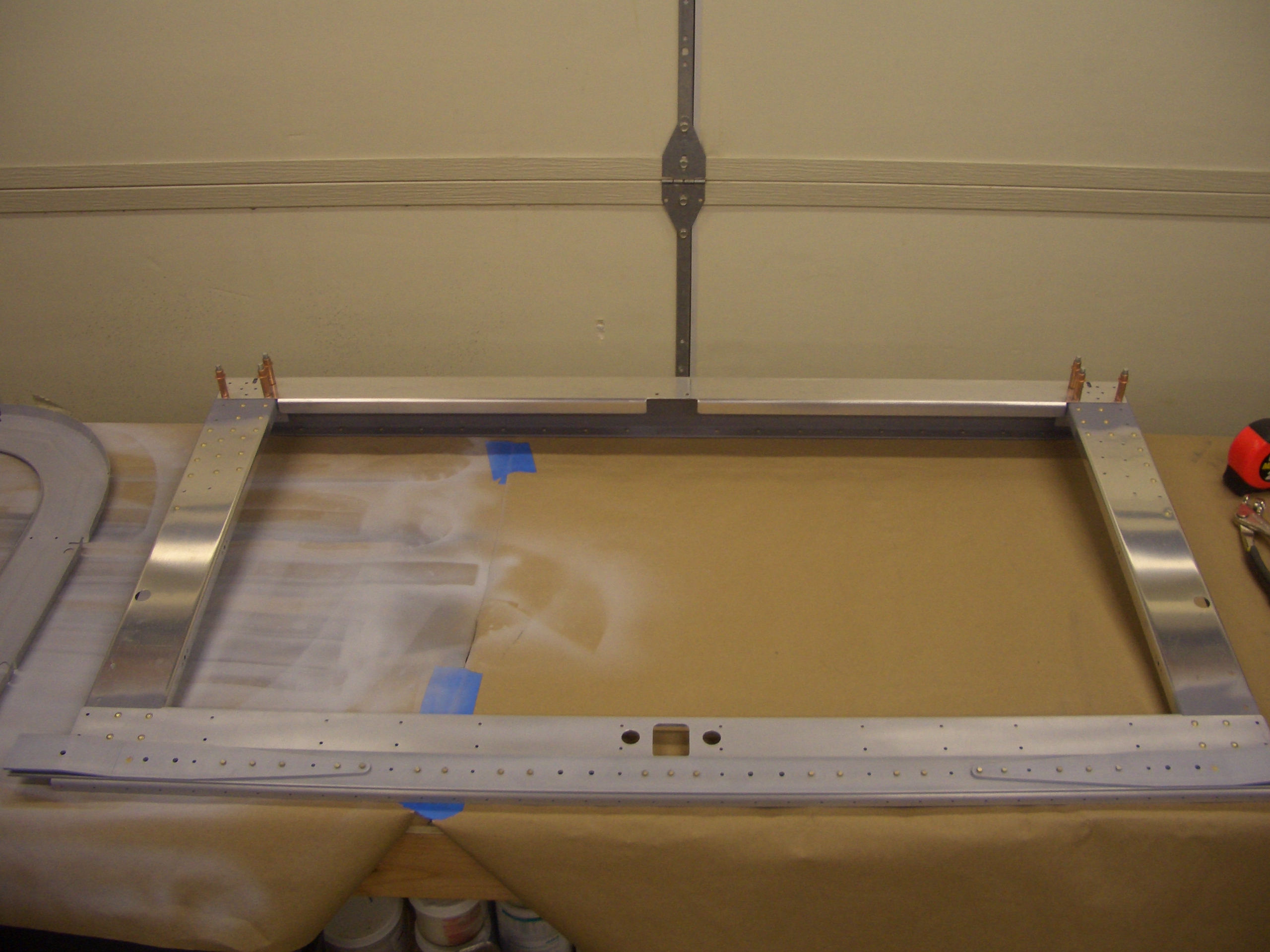
Here is the F-705 bulkhead riveted together. The clecos near the top are there because these pieces are riveted in conjunction with other parts.
This rivet needs to be a flush head since the seat belt attach anchor extends past this point.
Here is a closeup of the upper left portion of the F-705 bulkhead showing how many holes need to be left open for later riveting.
The upper seat adjustment pieces can also be riveted on now. I used some rattle can primer on these so that I can easily remove it later when I’m ready for final paint.
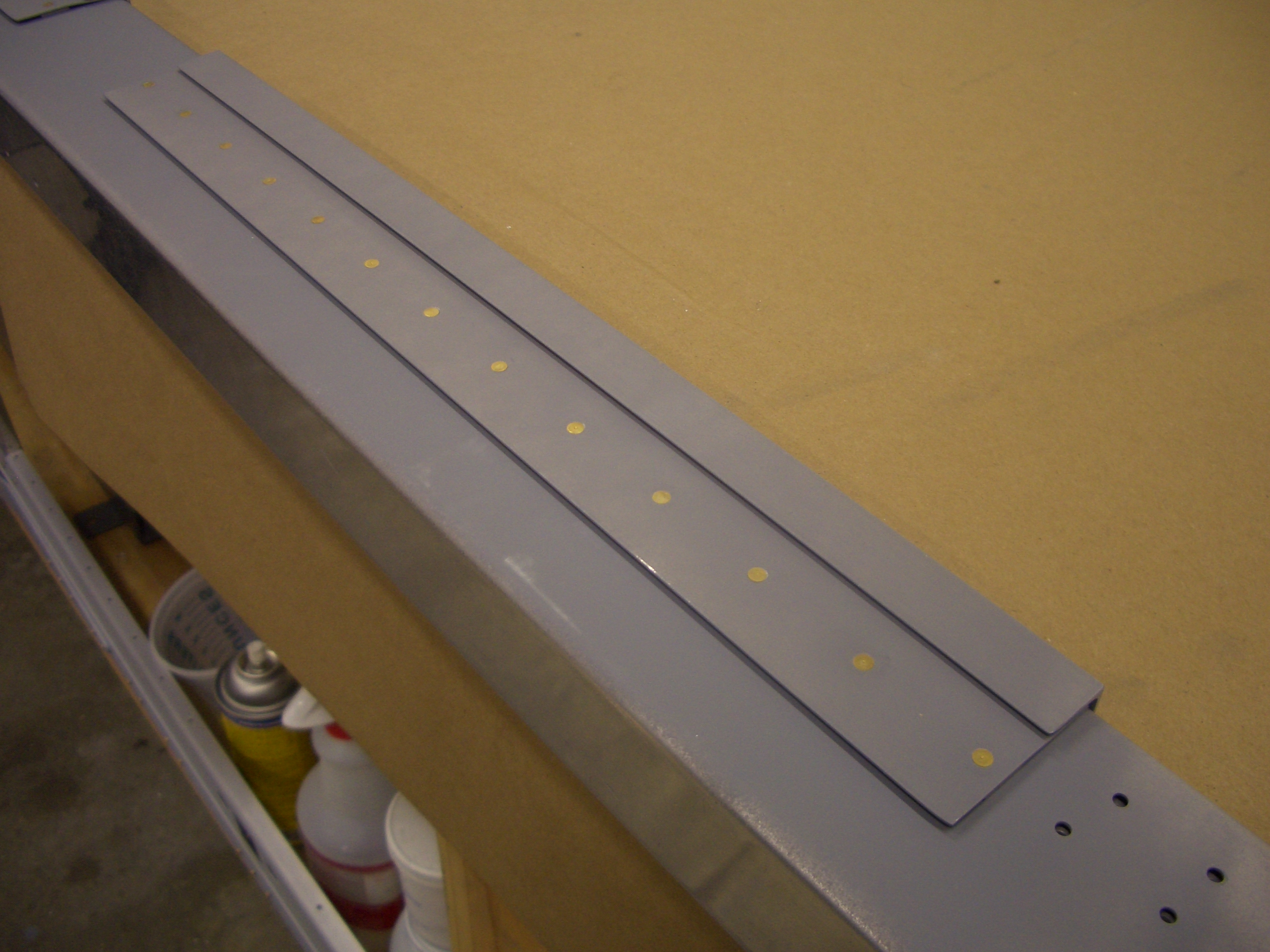
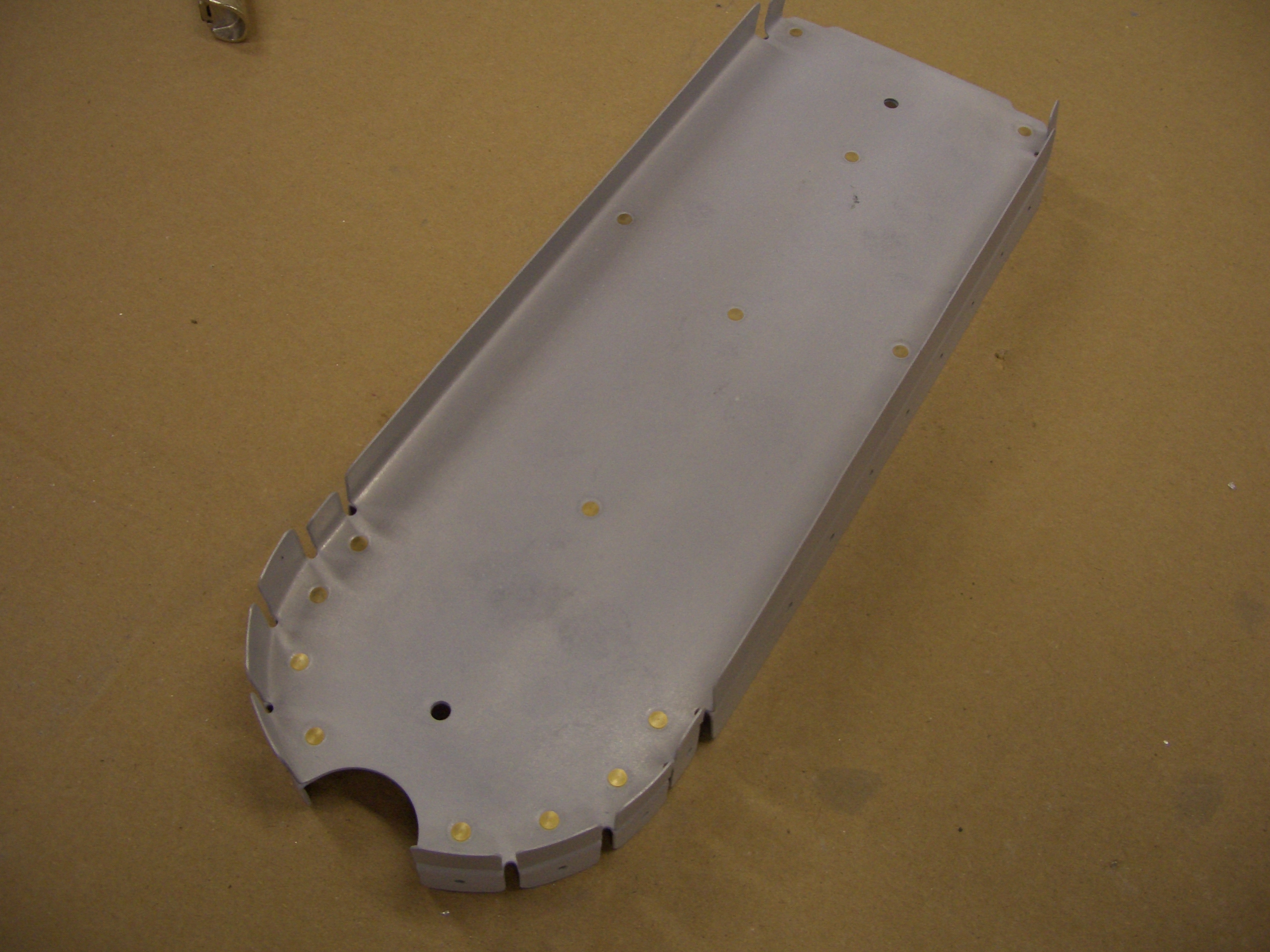
The rear bulkheads are primed with epoxy primer and just need a few rivets each to join the two halves together.
The F-706 bulkhead is riveted along the bottom, but the top is left clecoed since it is riveted in conjunction with a top skin rib.
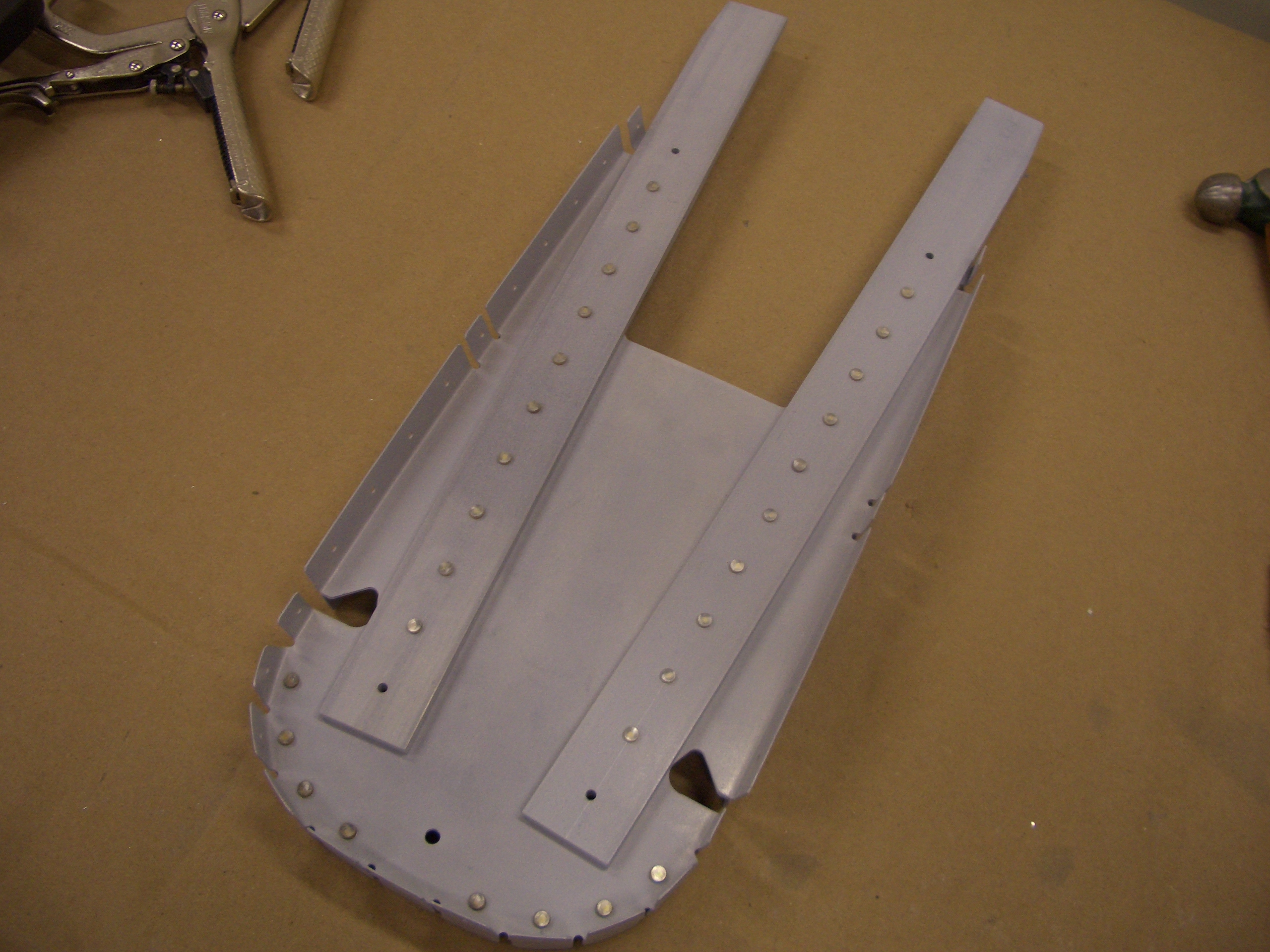
The F-711 bulkhead is riveted through the bars and around the lower curved section. The upper and lower hole in each bar is left unriveted for now.
The F-712 bulkhead is riveted together using flush rivets on the aft side since the vertical stabilizer rear spar attaches here.
The F-728 and F-729 ribs that support the elevator bellcrank are attached and everything except for F-728 is riveted in place.
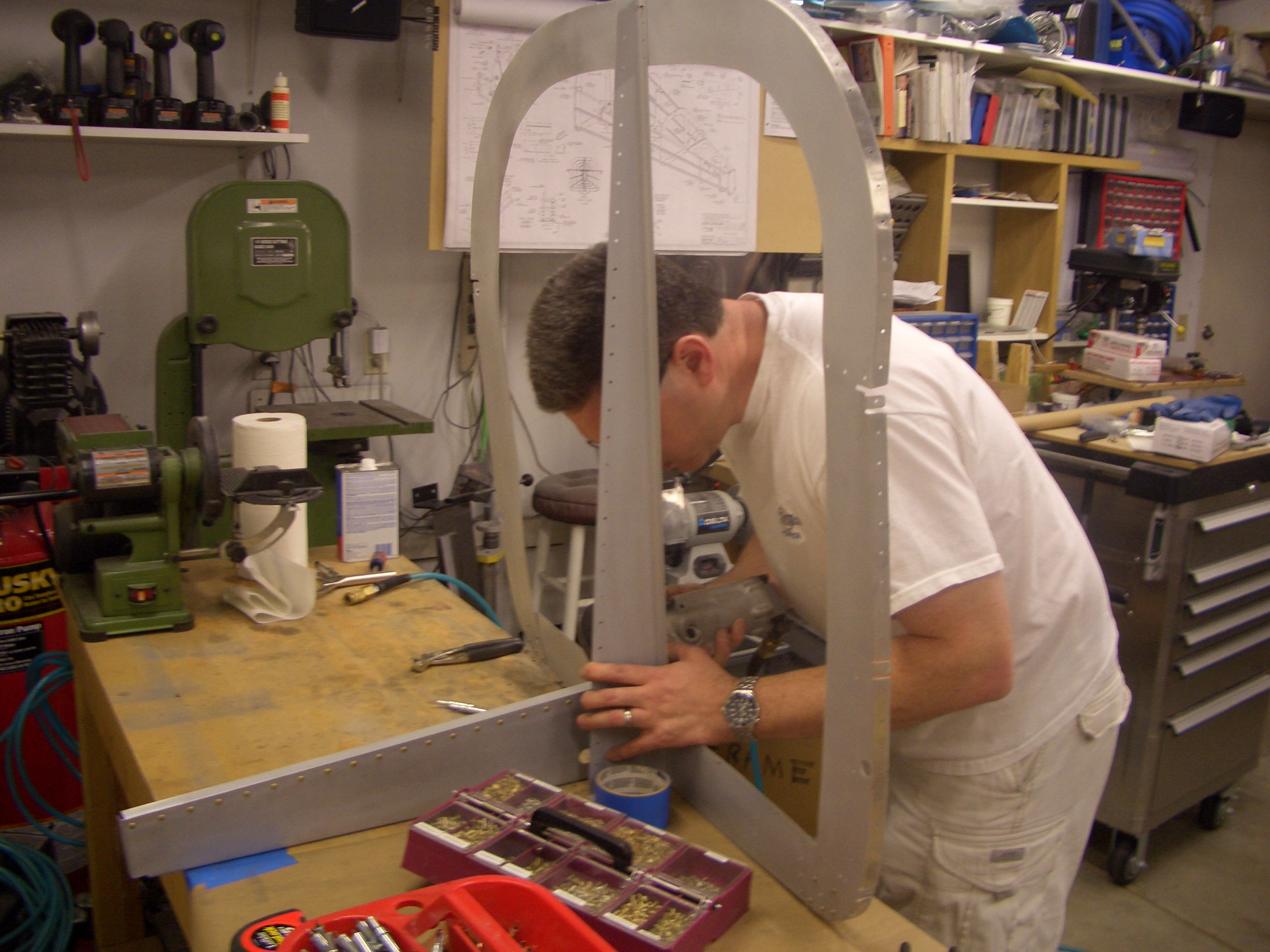
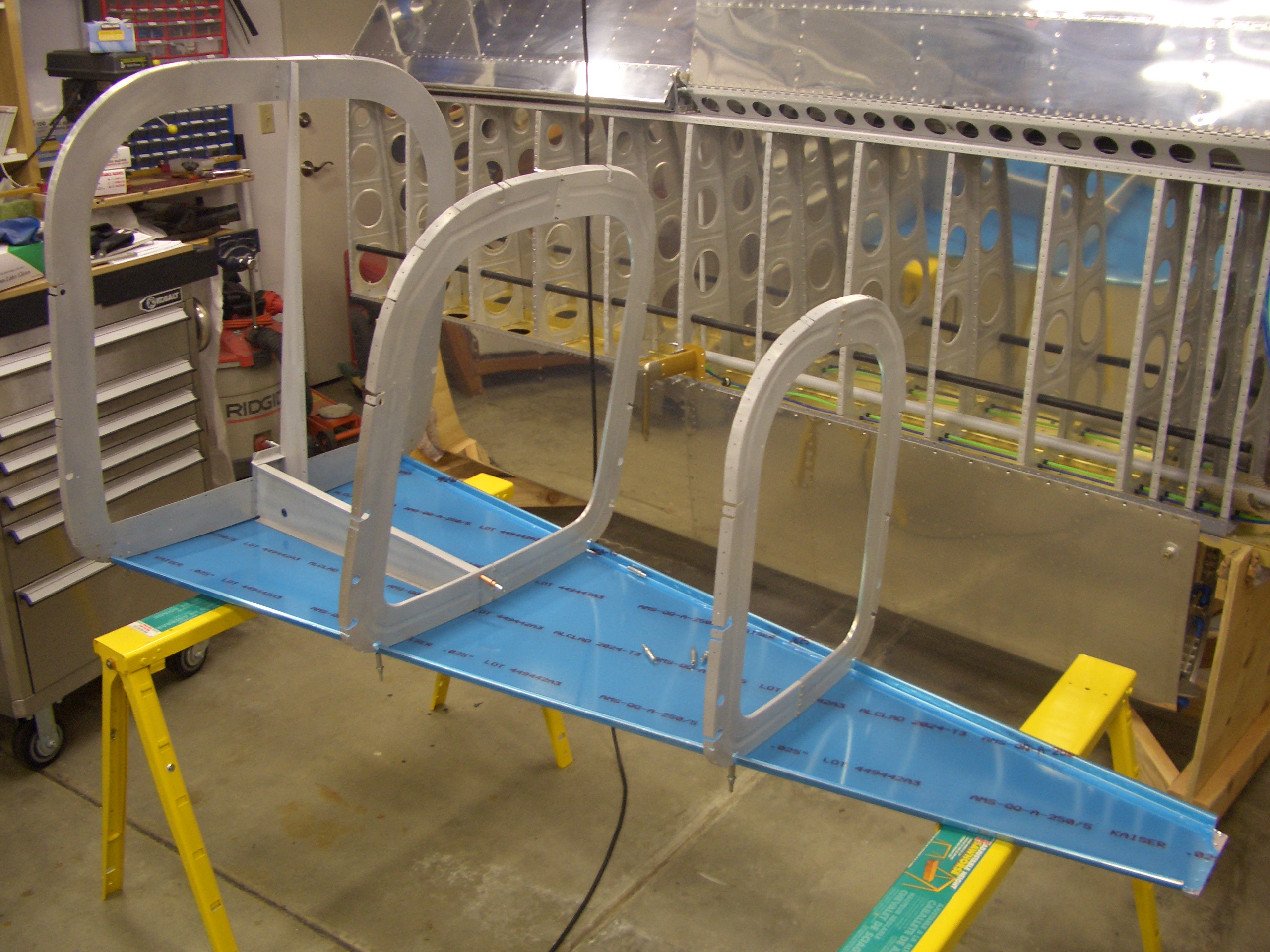
For fun, I clecoed the F-706, F-707 and F-708 bulkheads to the bottom skin to see how everything fits together. The hole alignment is pretty poor. The bulkheads will definitely need some fluting before everything aligns.
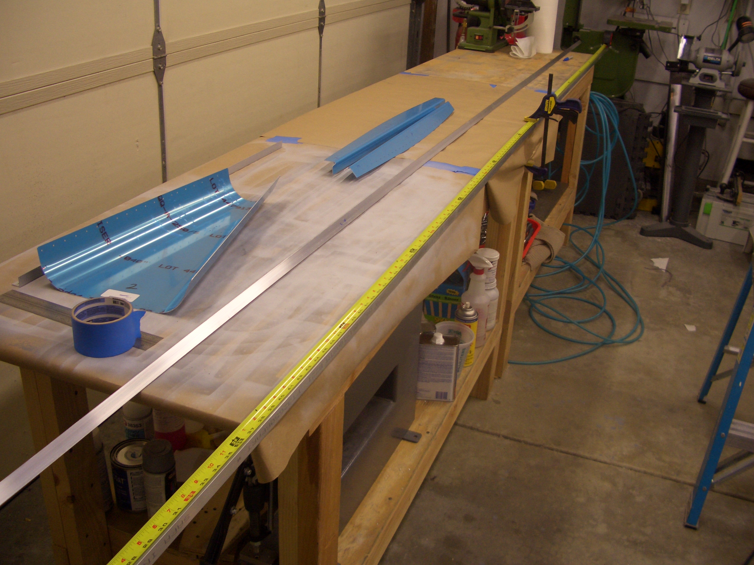
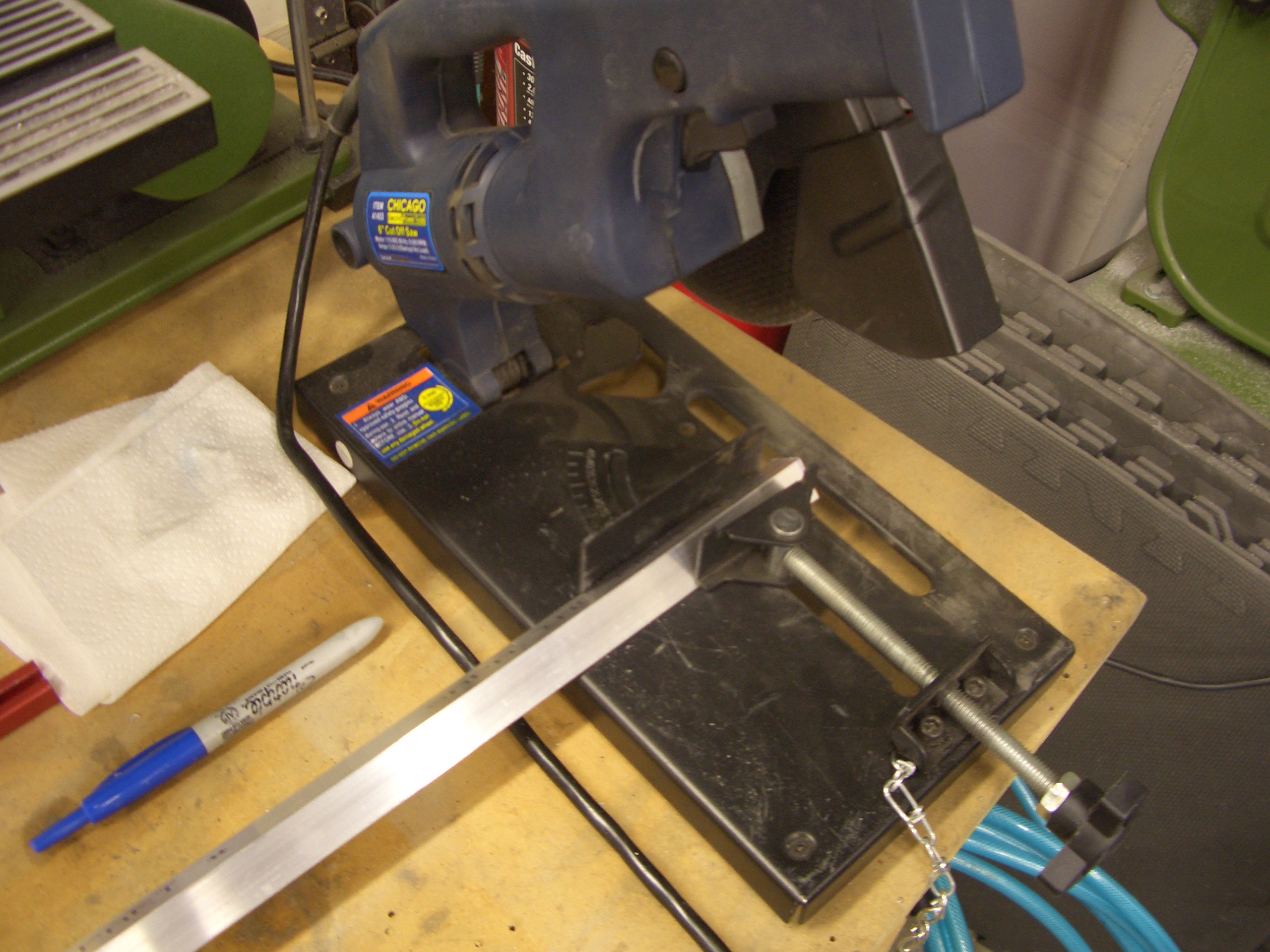
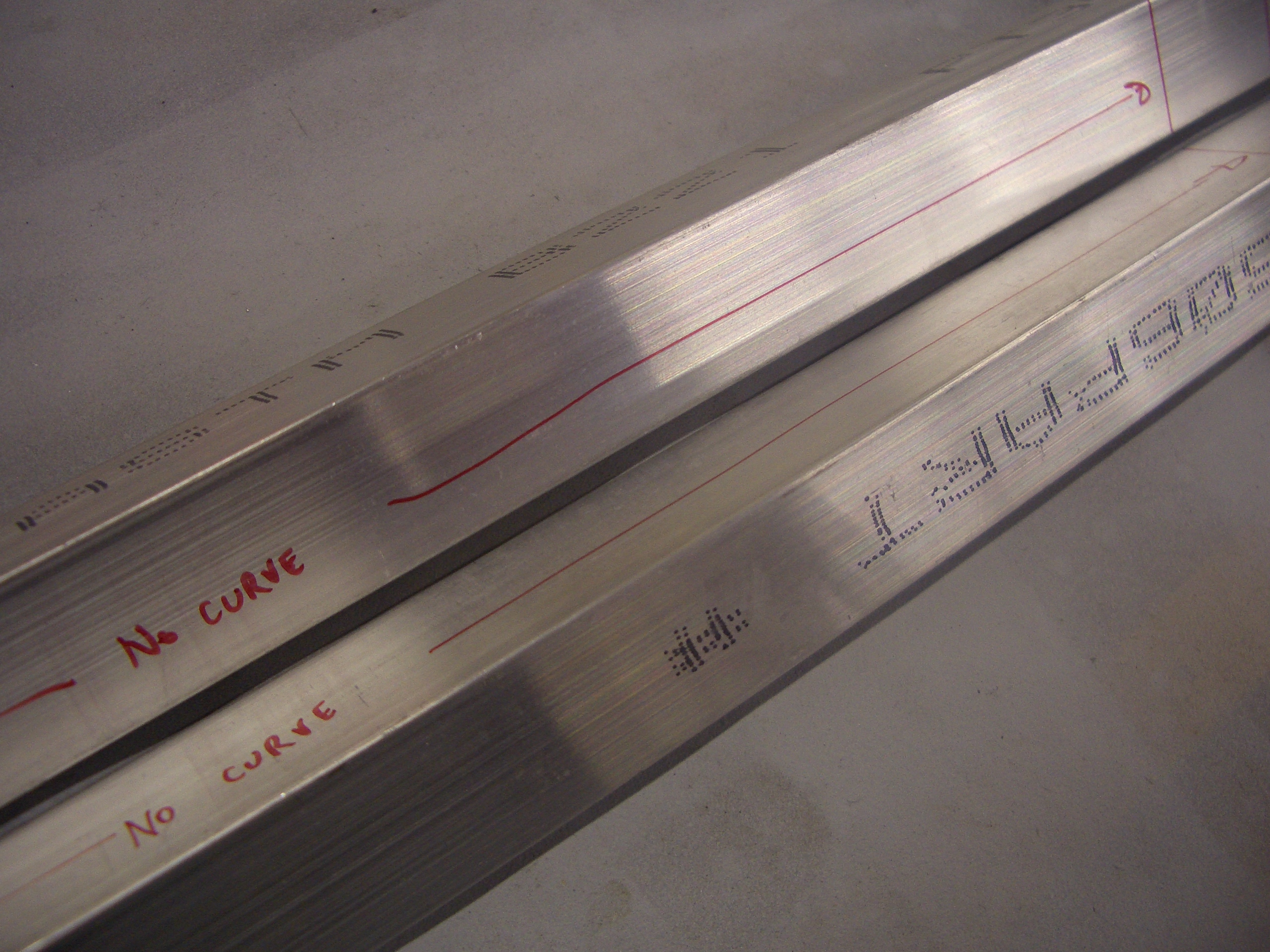
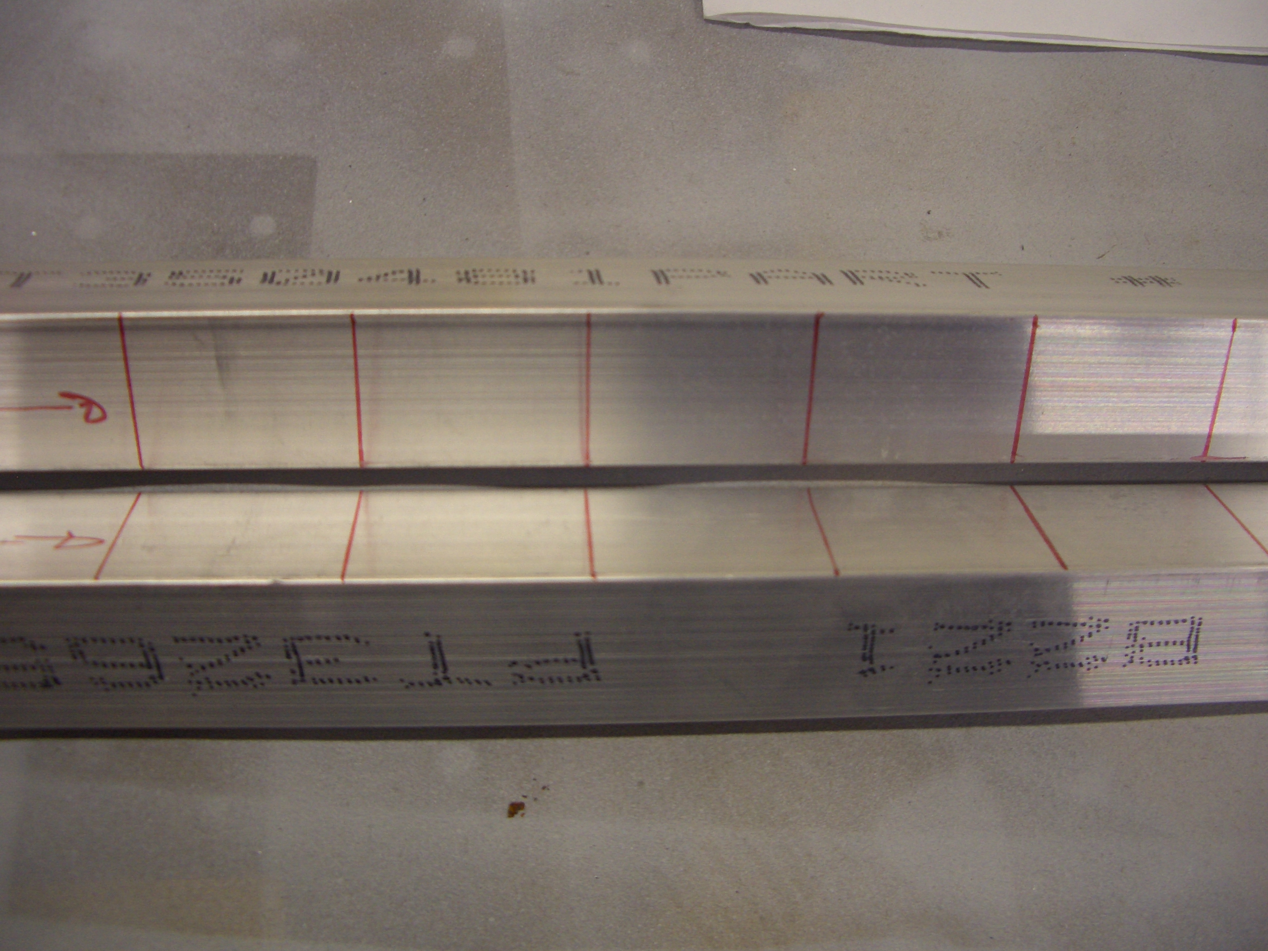
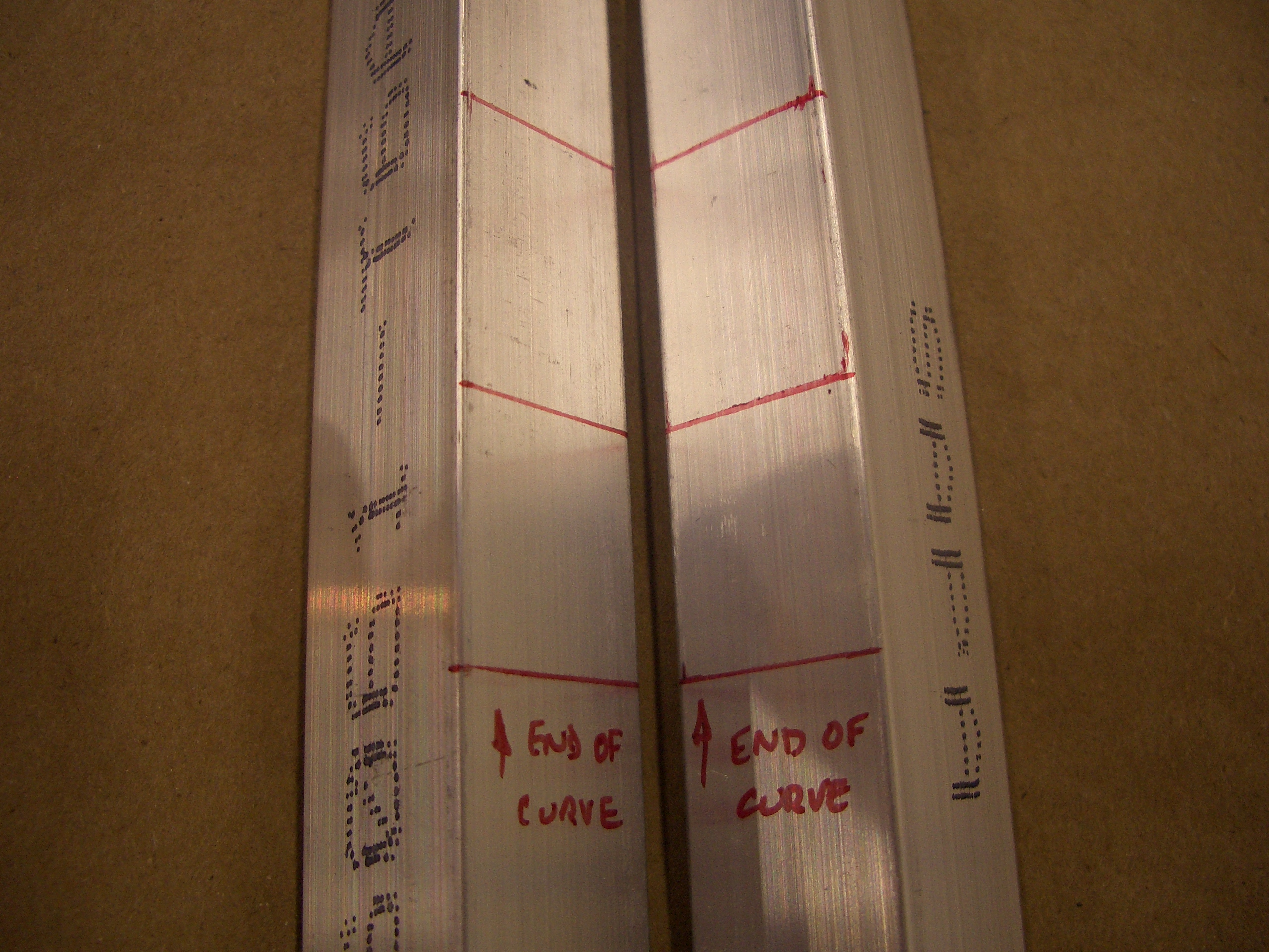
Started Longerons
I started working on the longerons tonight. First up is to cut them to length. This is a critical cut because replacing these 15′ long angles would be very expensive (both in material cost and in shipping). These need to be cut to precisely 173 7/16″. Since the ends of tape measures can have some slop in them, a trick to get more precise measurements is to position the tape measure at the 1″ mark. You do have to be sure to add 1″ to your measurement to account for this though.