Finished Elevator Counterweight Clearance

I finished trimming the horizontal stabilizer to allow for clearance of the elevator counterweights.  I’m allowing for 1/8″ clearance on the front edge to the center of the counterweight (where the screws are).


The clearance between the side of the horizontal stabilizer and the inboard edge of the counterweight skin is also 1/8″ and is perfectly even here on the left elevator.


The right elevator is off a little bit.  The clearance on the back end is 1/8″, but the clearance on the front end is 5/32″ (it was over 6″32″, but a little leaning on the elevator, while it was standing up on the counterweight, brought it in slightly.  I might have been able to bring it in the rest of the way, but it would have required more force on the elevator than I was comfortable applying).  This is almost unnoticeable, so I’m happy with it.  With tonight’s work behind me, I’m done with the elevators other than the fiberglass tips.

Drilling Elevator Horns to Center Bearing

I purchased a drill bushing from McMaster-Carr to ensure the elevator horns were drilled directly in line with the center bearing.  The bushing was a couple of thousandths too large to fit in the center bearing, so I spun it in my drill press and used some emery cloth to take it down until it fit.  Here is the bushing fit through the bearing and pressed up against the left elevator control horn.


The bushing has a center hole sized for a #40 drill bit.  Using a bit of Boelube, I drilled through the bushing to make a pilot hole in the elevator horn.


I stepped up the size of the hole using a couple of intermediate bits and finished with a 1/4″ unibit.  After a bit of deburring, here is the finished hole.  I then repeated the process for the right elevator control horn.


After reinstalling the elevators, I slipped an AN4-14A both through to check the fit.  The holes are in perfect alignment.  Various washers will eventually be installed here to take up the intermediate space.

Finished Trim Tab and Fitting Control Surfaces

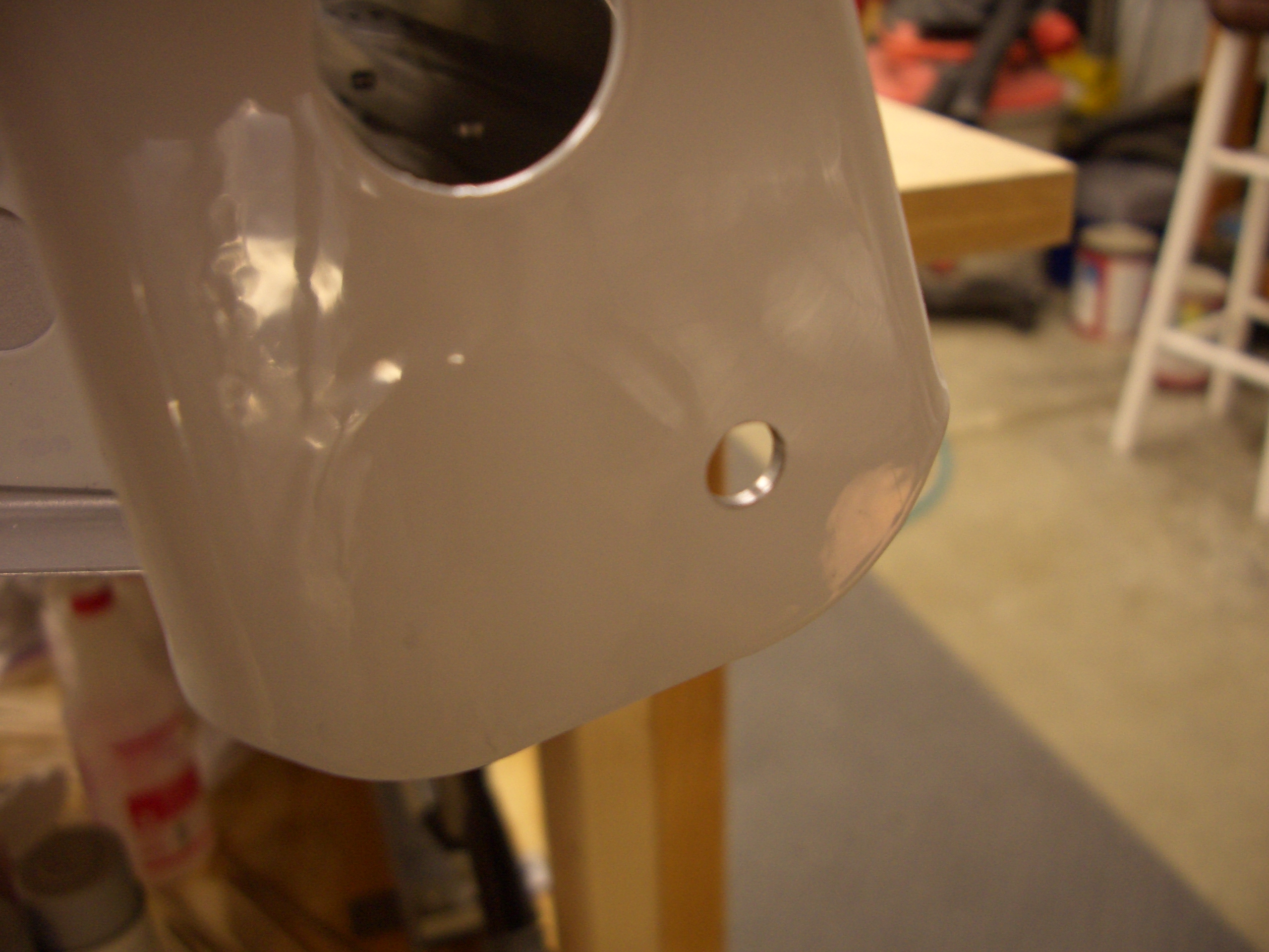
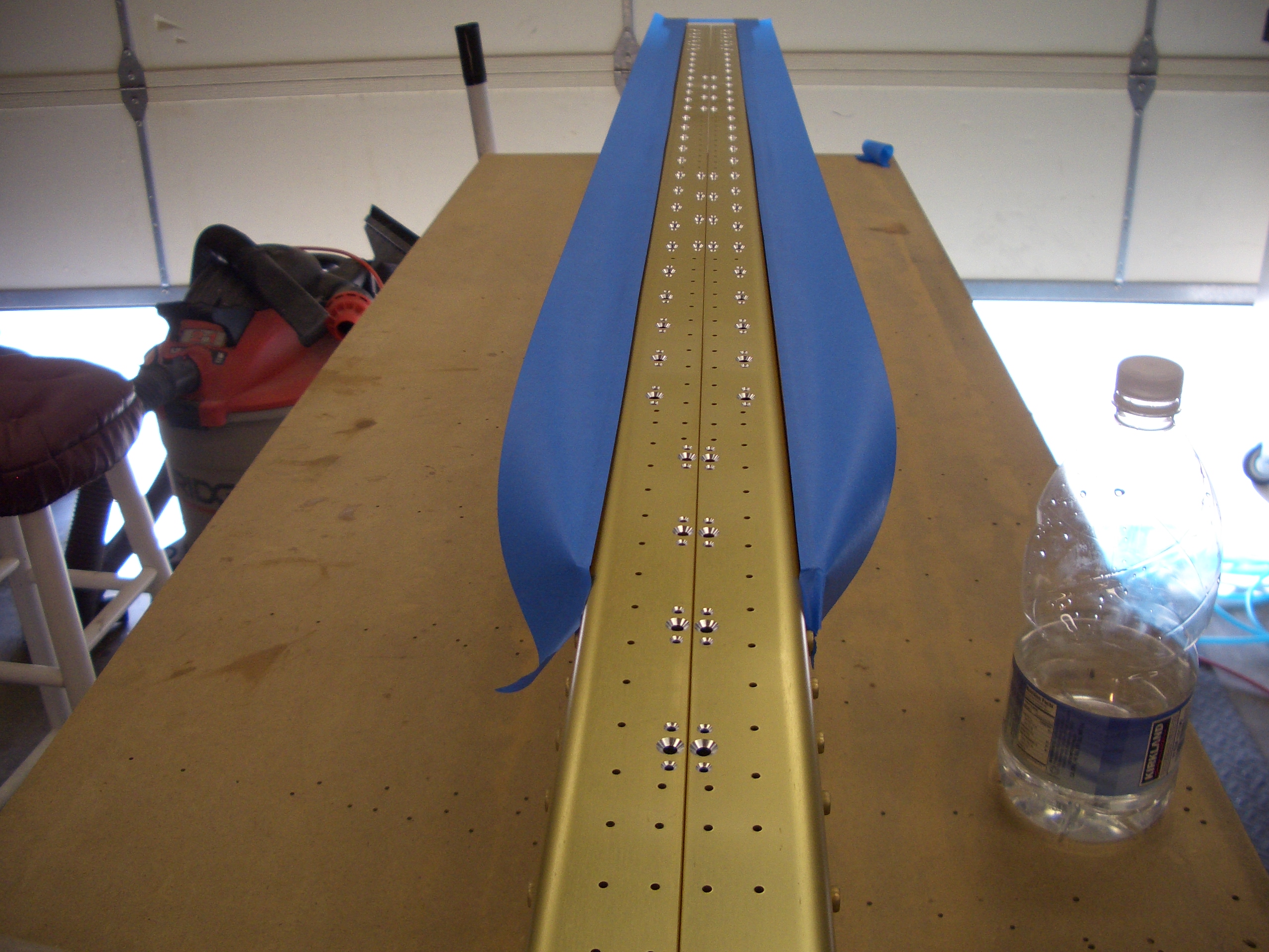
I finished riveting the trim tab with the exception of a couple of pop rivets that I need to order.  I’m really happy with how this turned out.  It’s not perfect, and I’m sure I could do better after I get more experience, but it turned out really well.


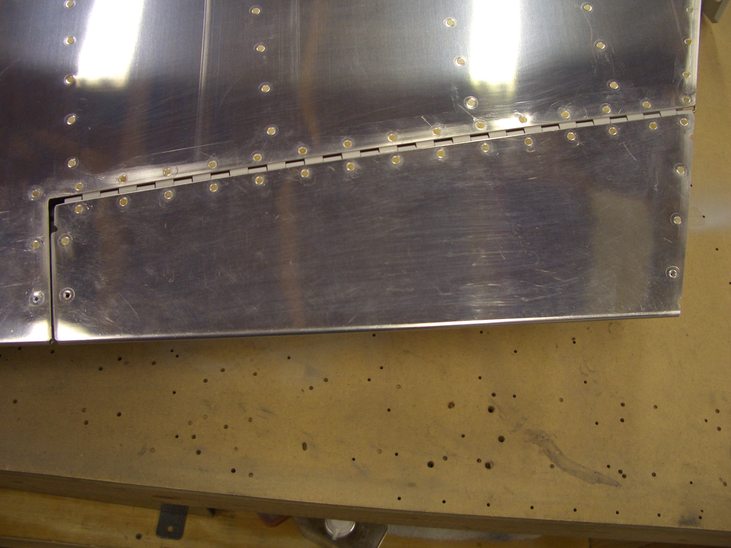
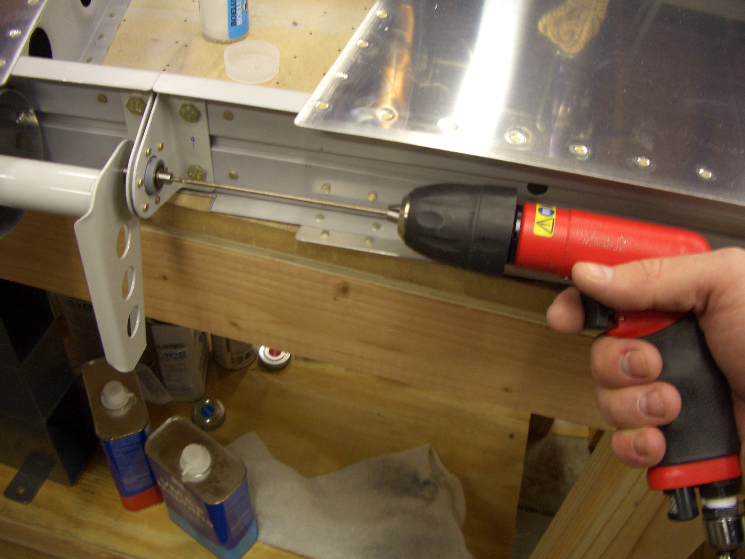
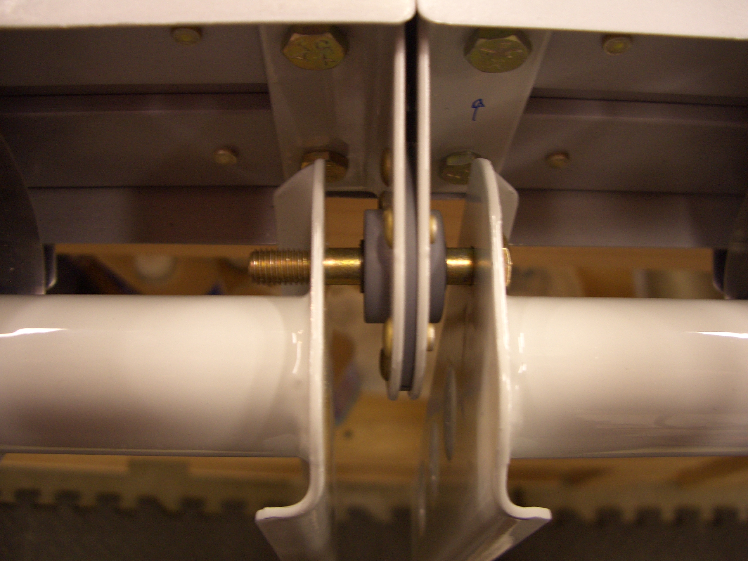
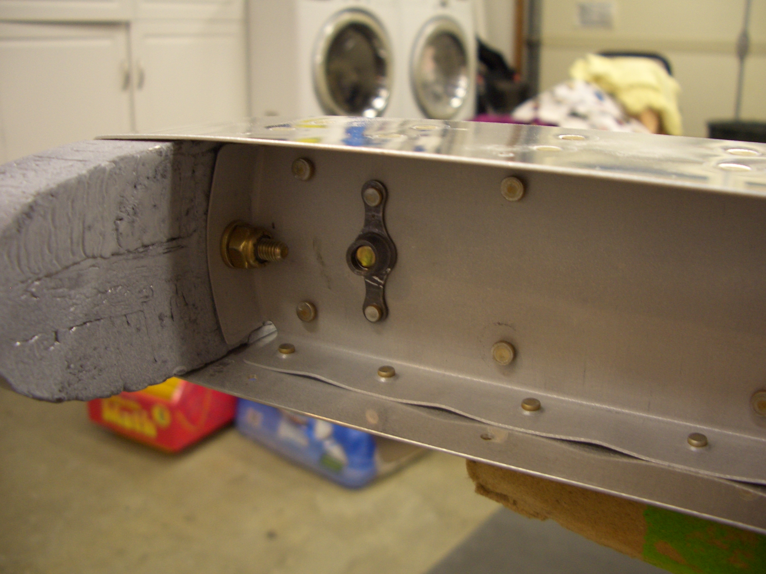
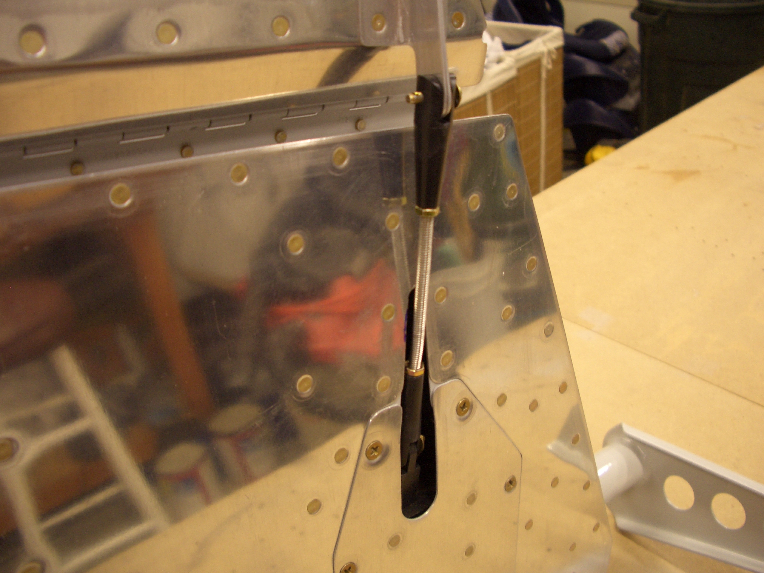
Here is the bottom side with the trim servo hooked up.  I’m not getting anywhere near the +25º/-35º travel the manual states is optimal, so I’ll have to call Van’s about that, but at least it’s all hooked up and working.


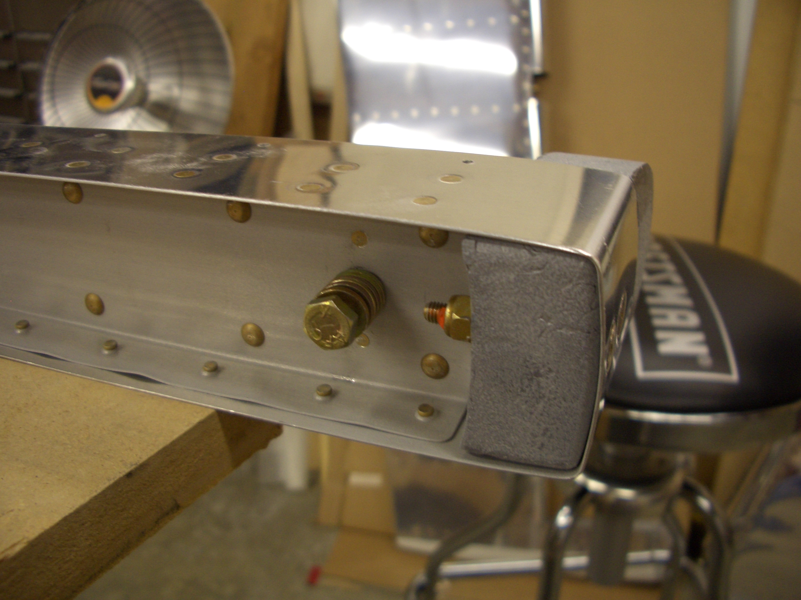
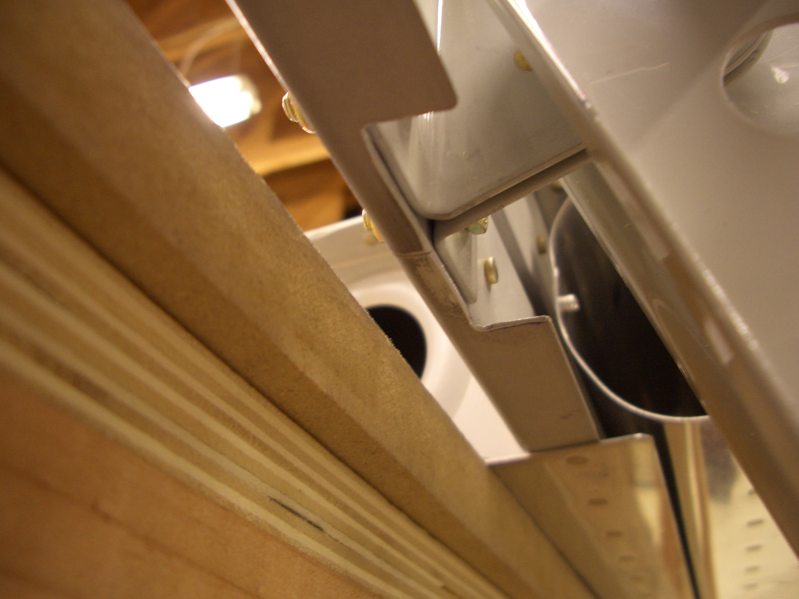
Here’s a closeup of the trim tab push rod.  I’ll probably need to file the edges of the opening in the elevator to get a little more clearance, but that can wait.


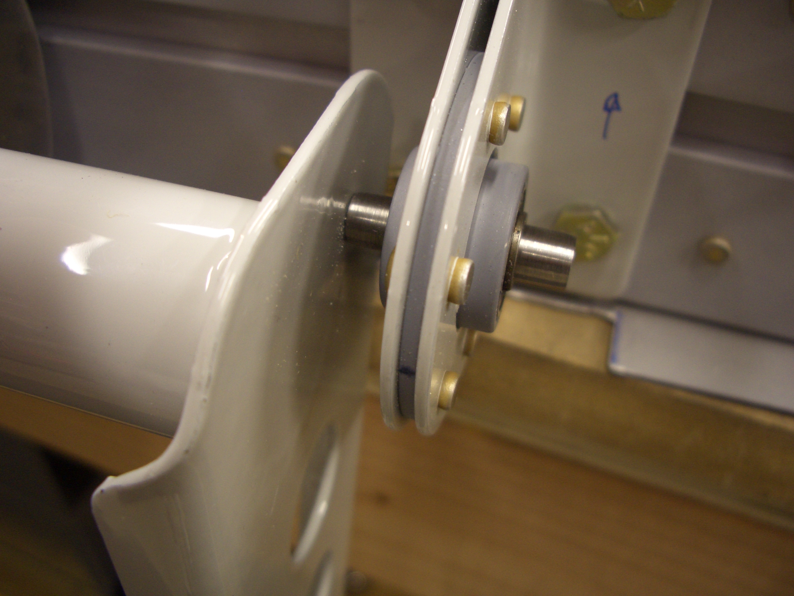
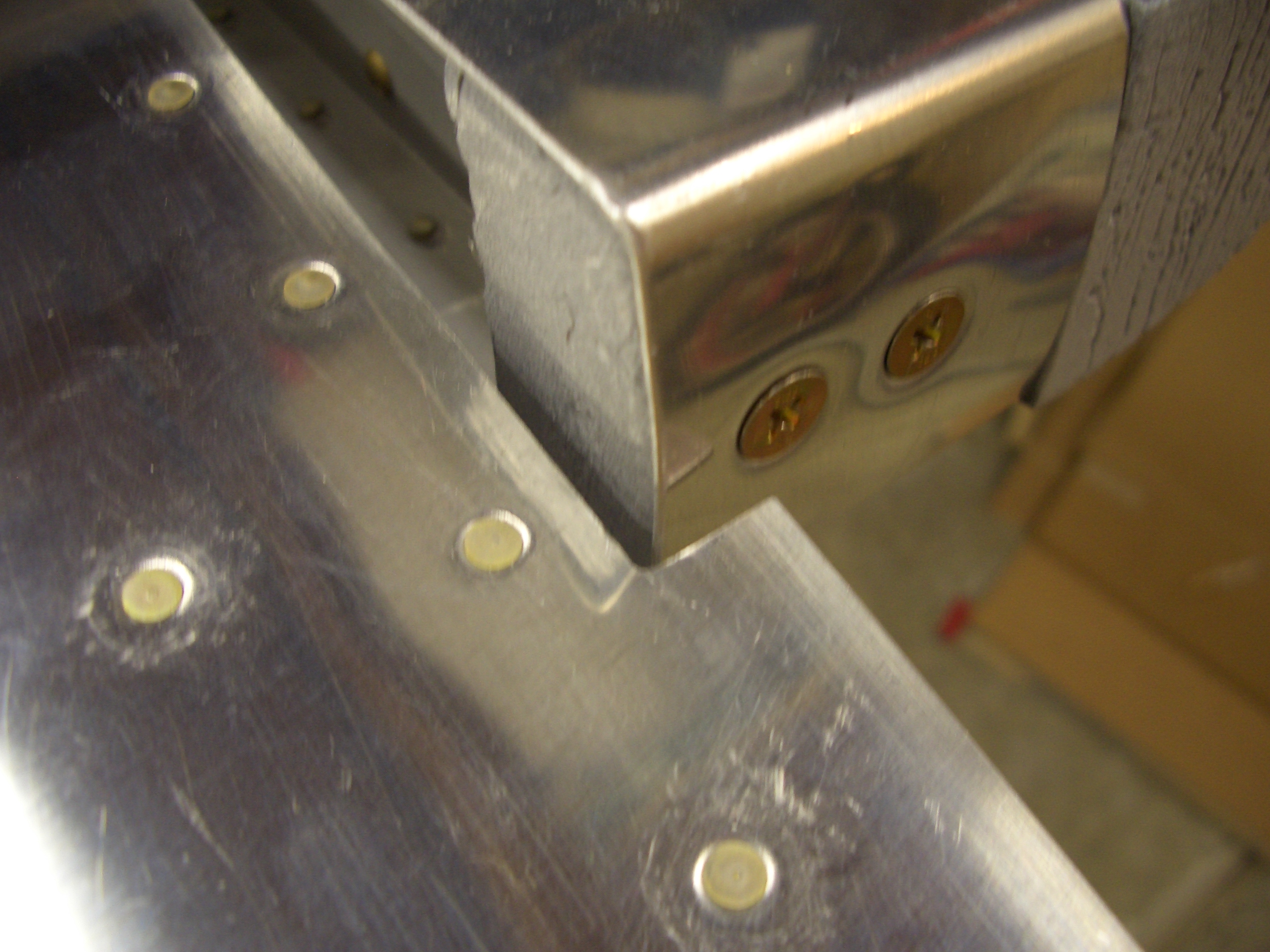
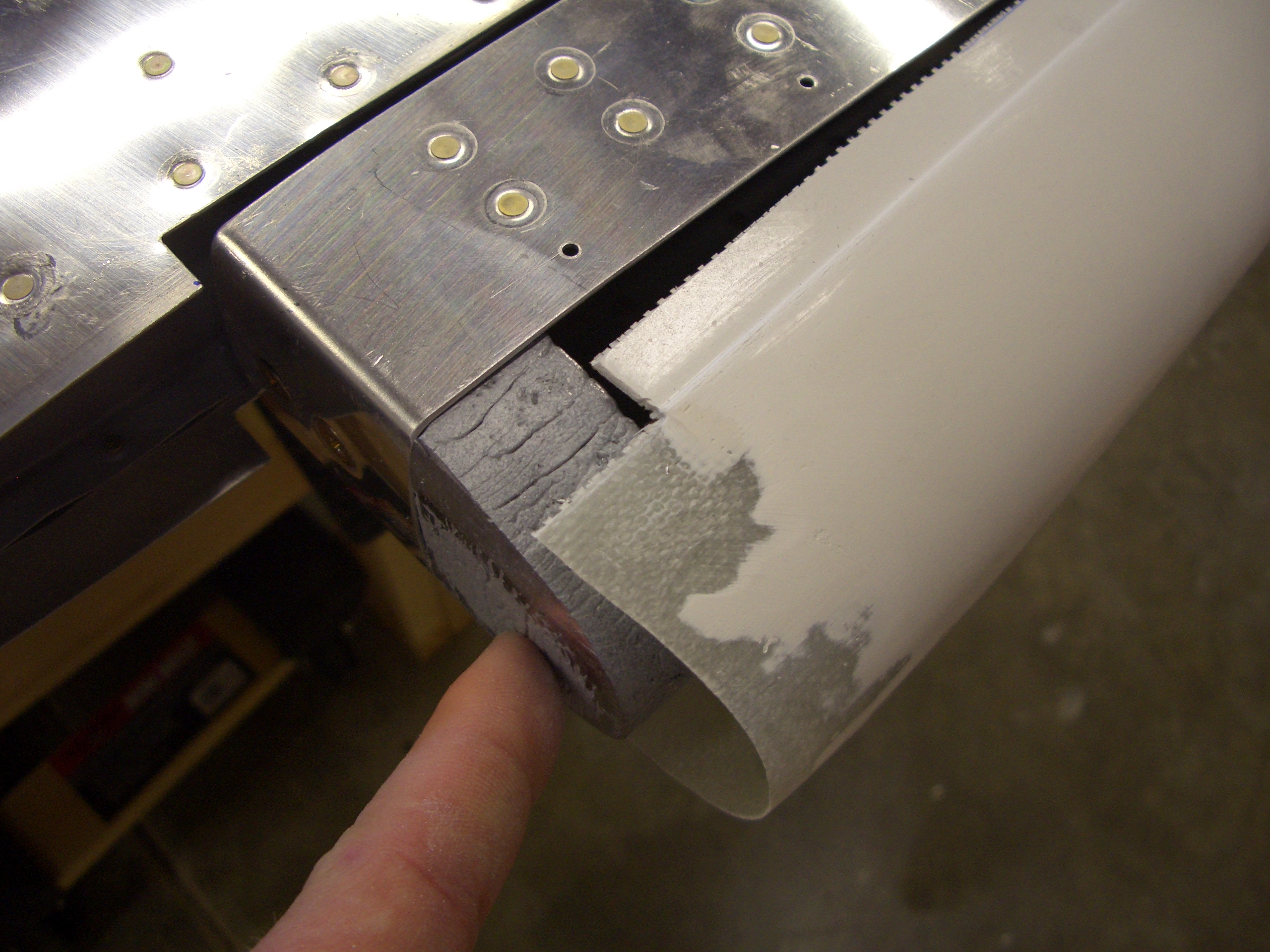
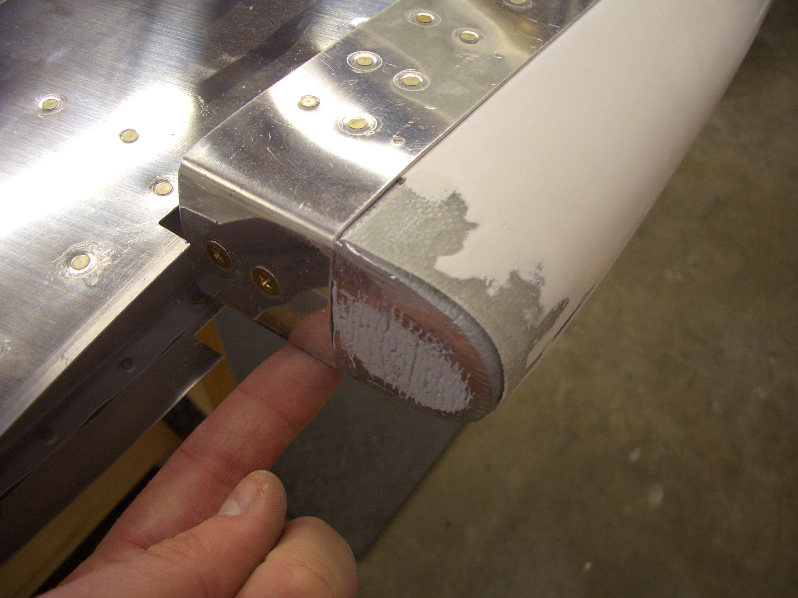
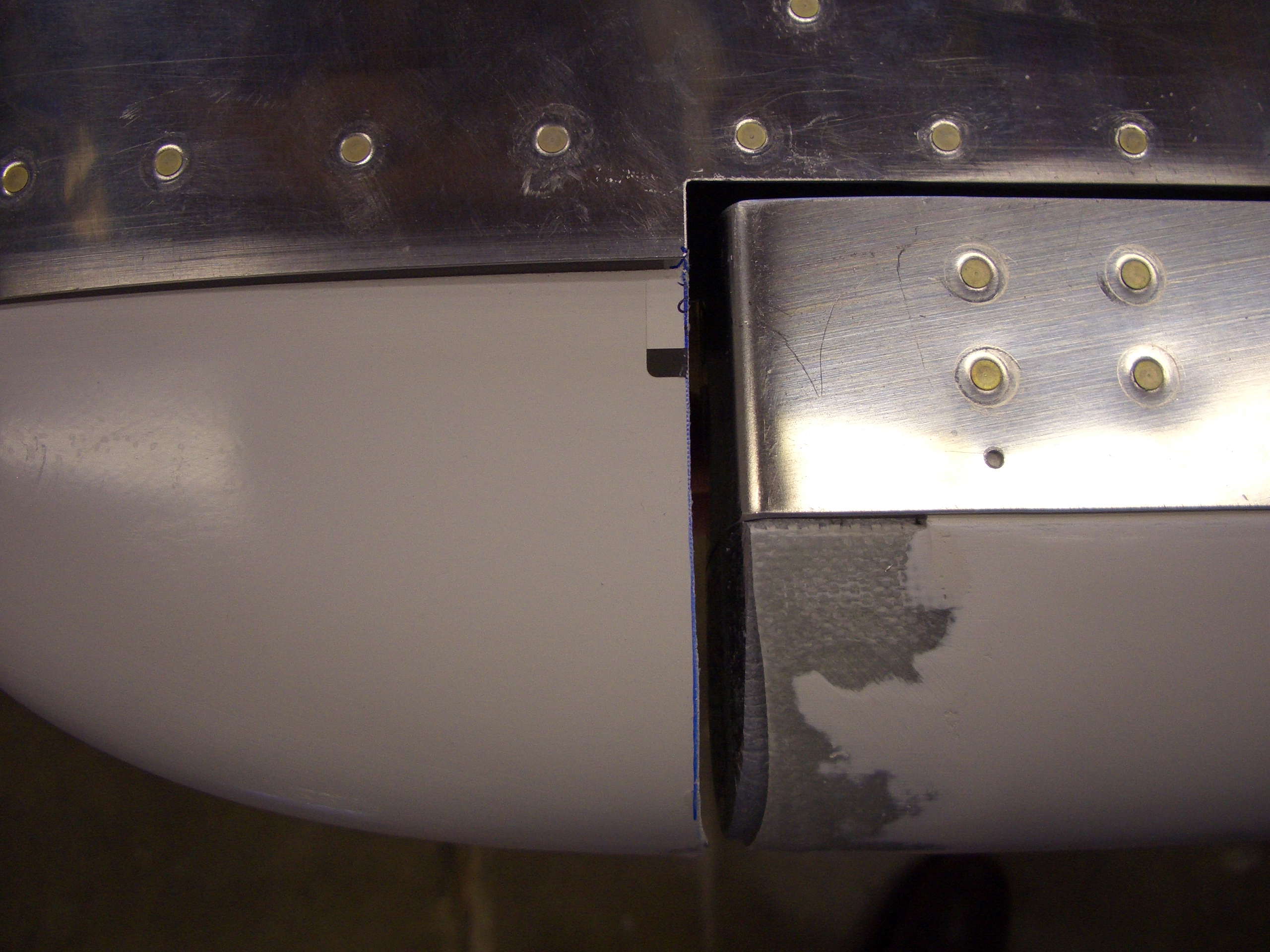
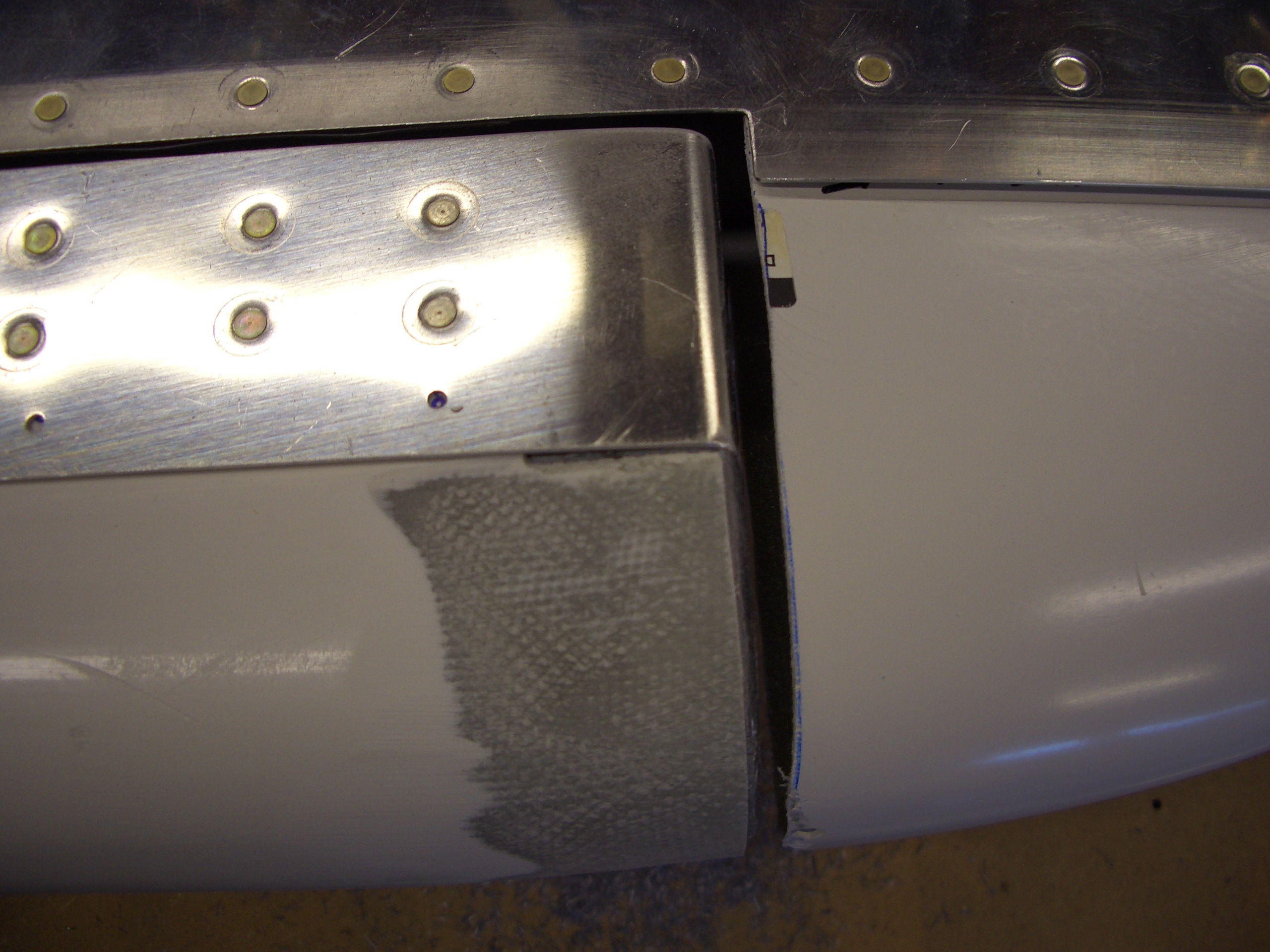
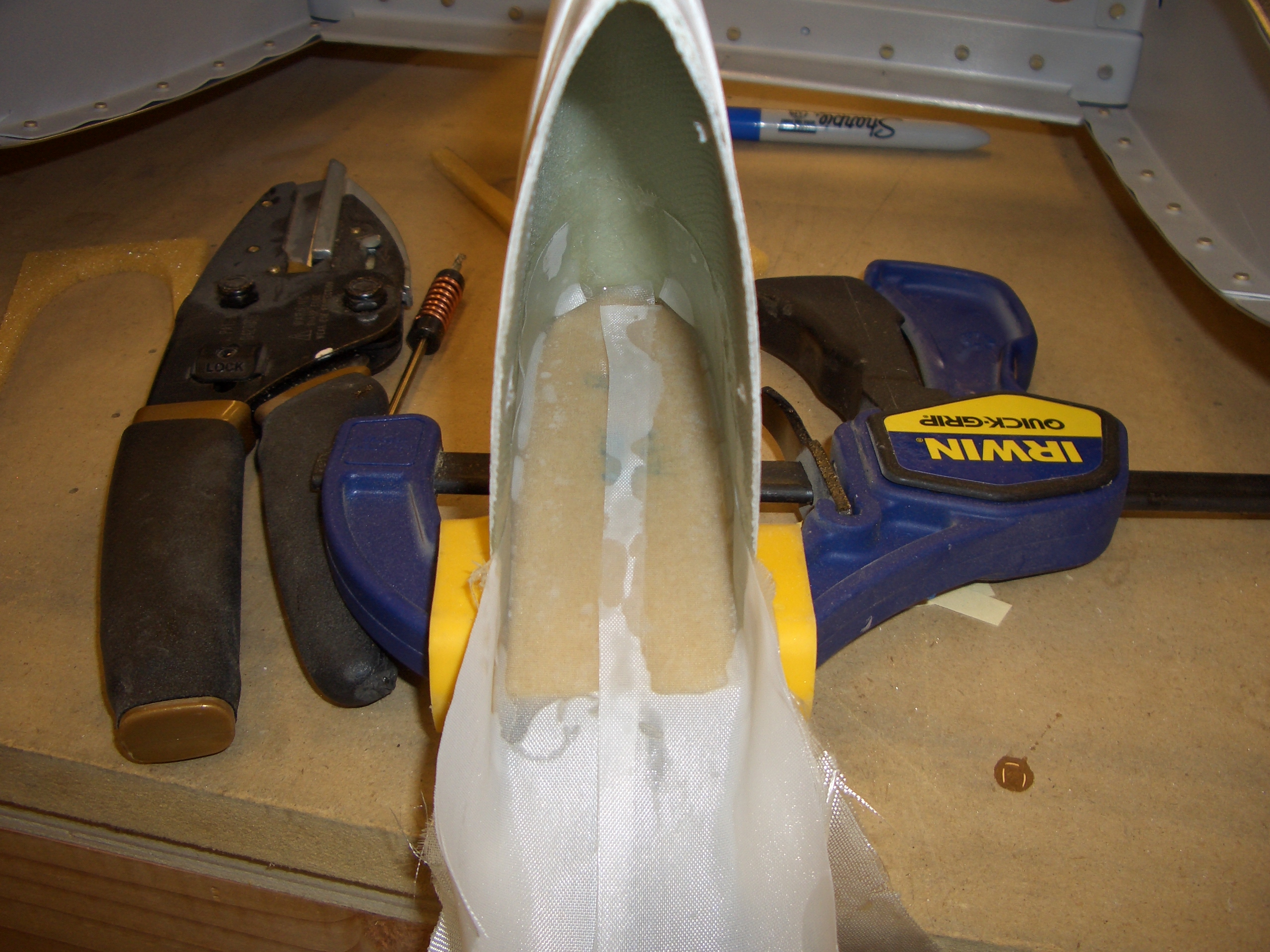
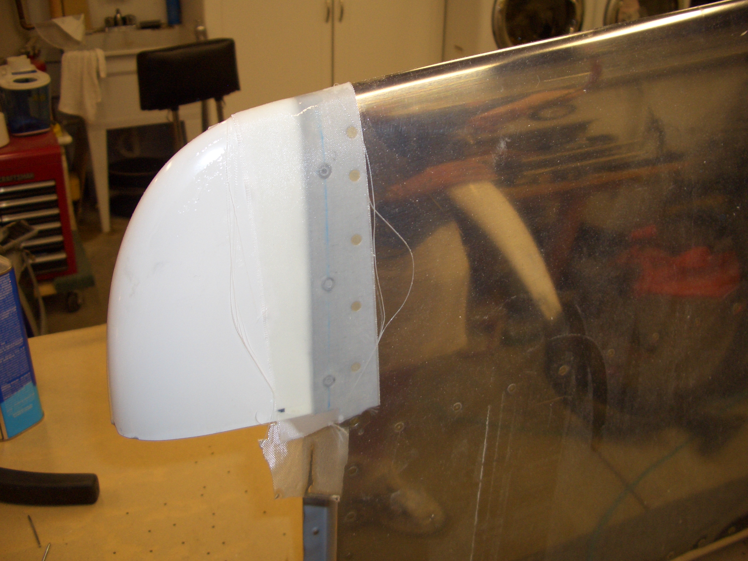
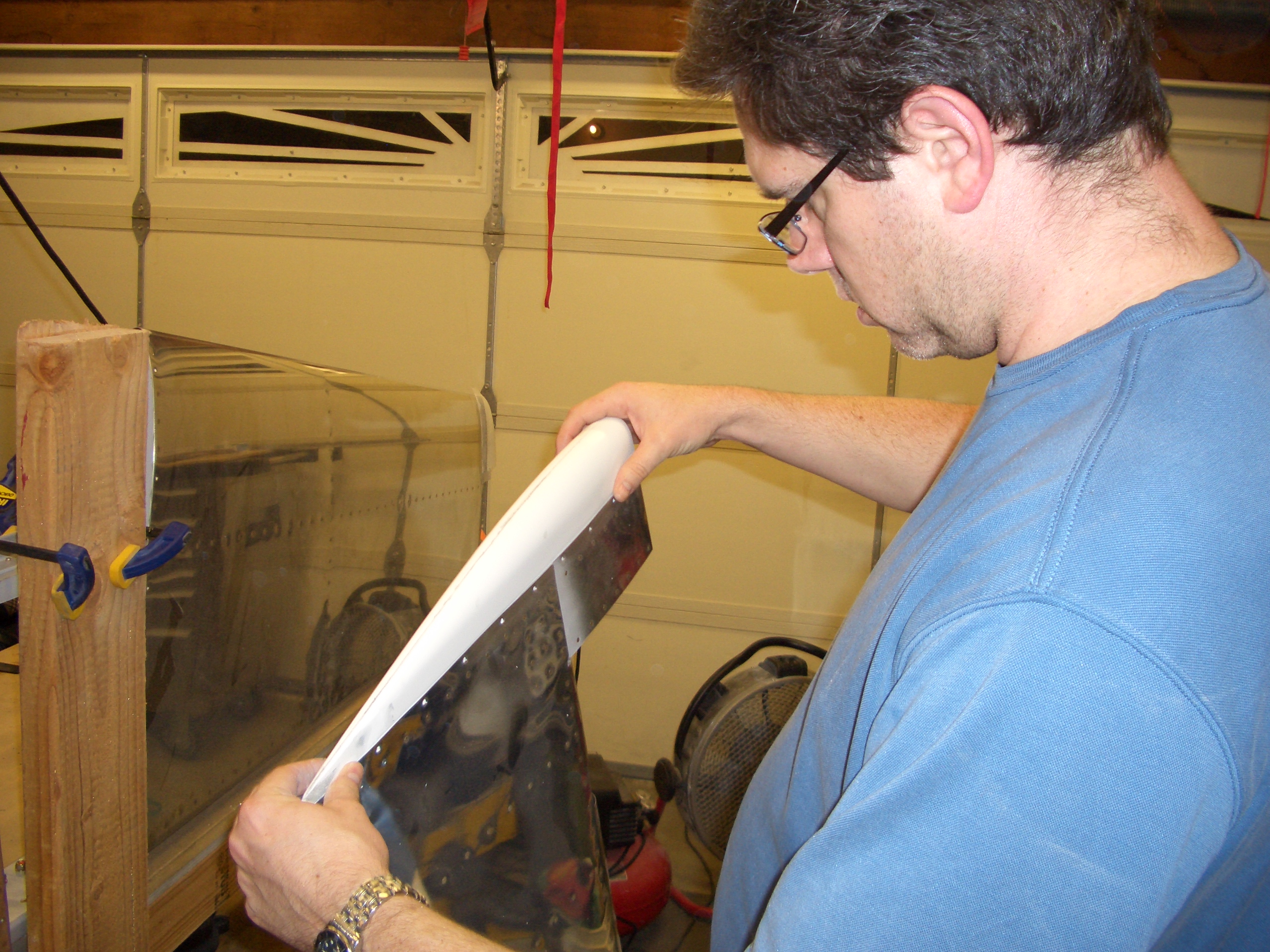
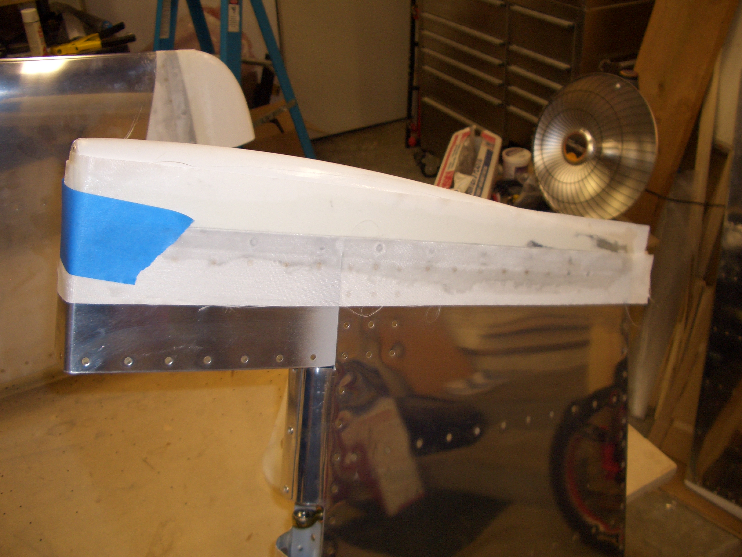
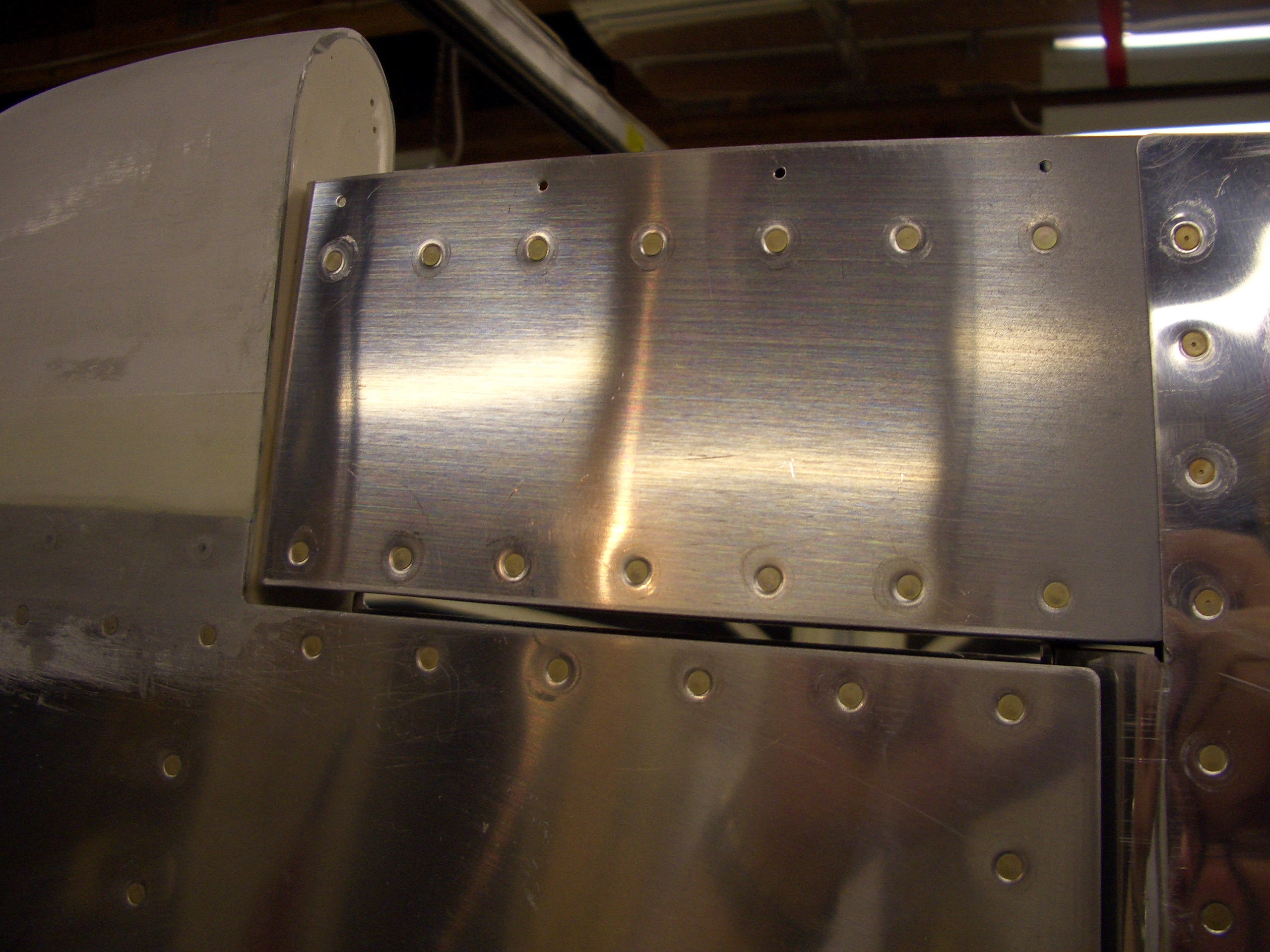
I pulled down the rudder and fit in to the vertical stabilizer.  The clearance between the vertical stabilizer tip and rudder counterbalance skin is too tight right now, but I’ll open it up a bit when I do more of the fiberglass work.


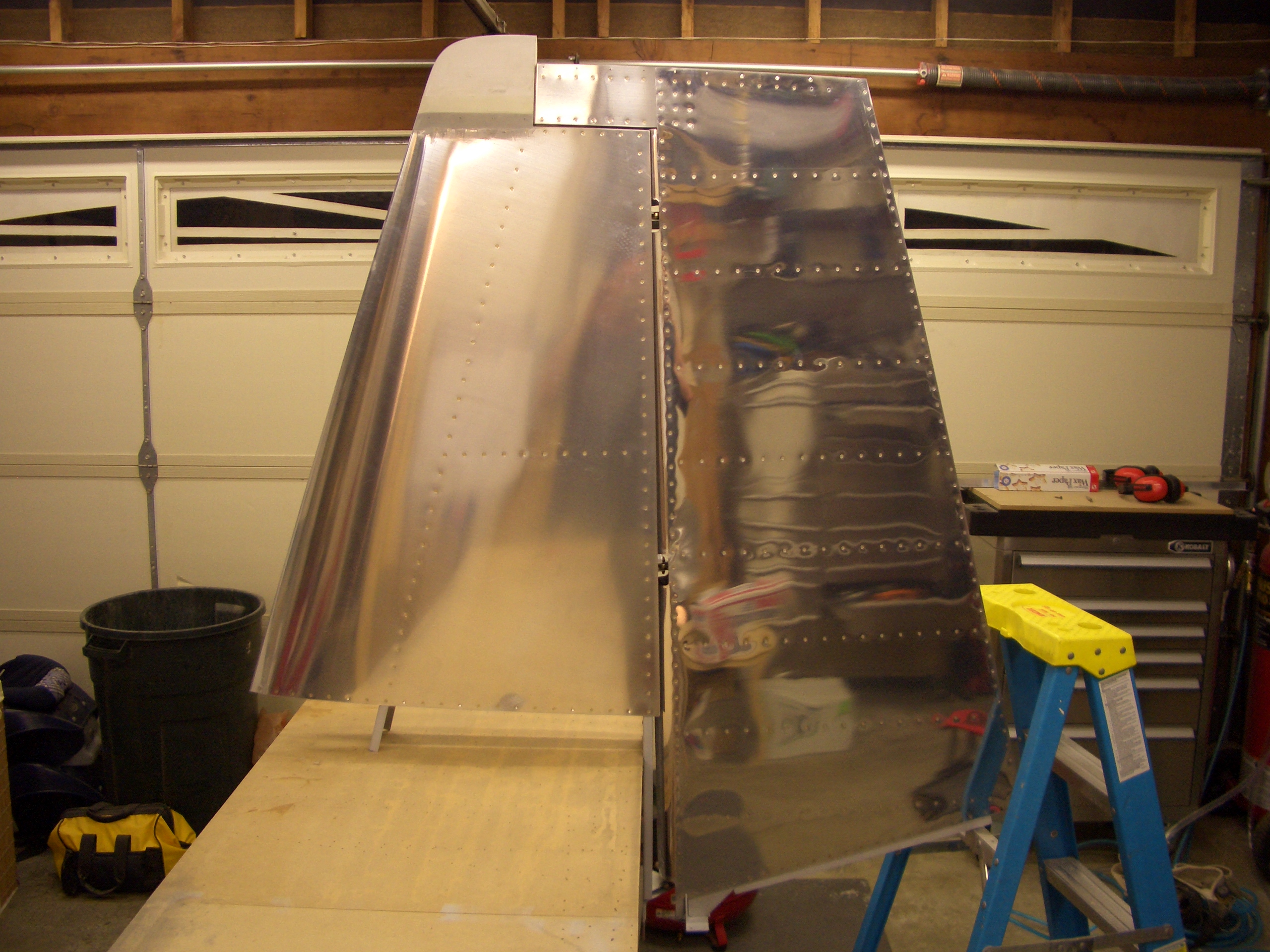
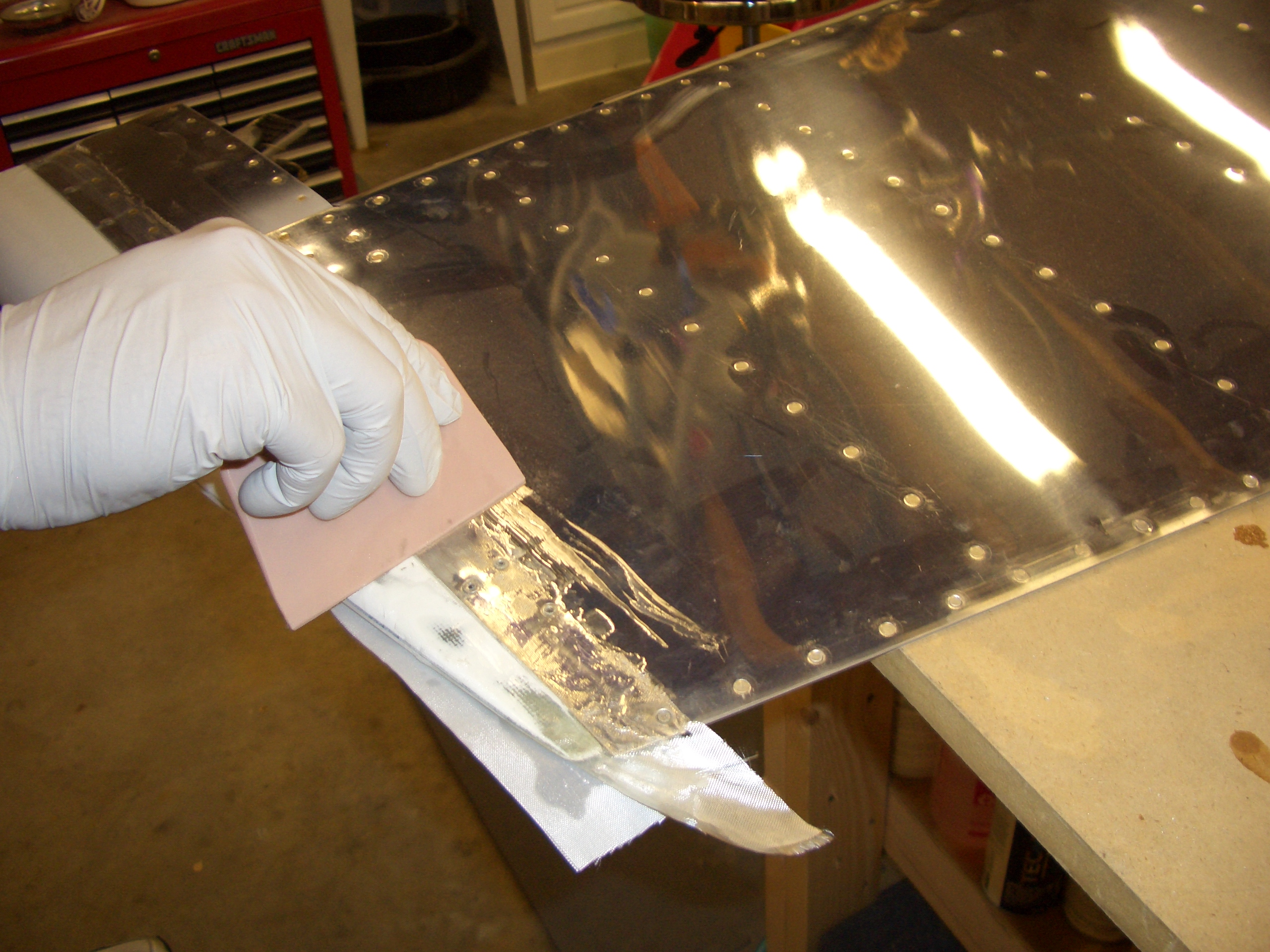
The gap between the lower edge of the counterbalance skin and the upper edge of the vertical stabilizer is nice and uniform though.


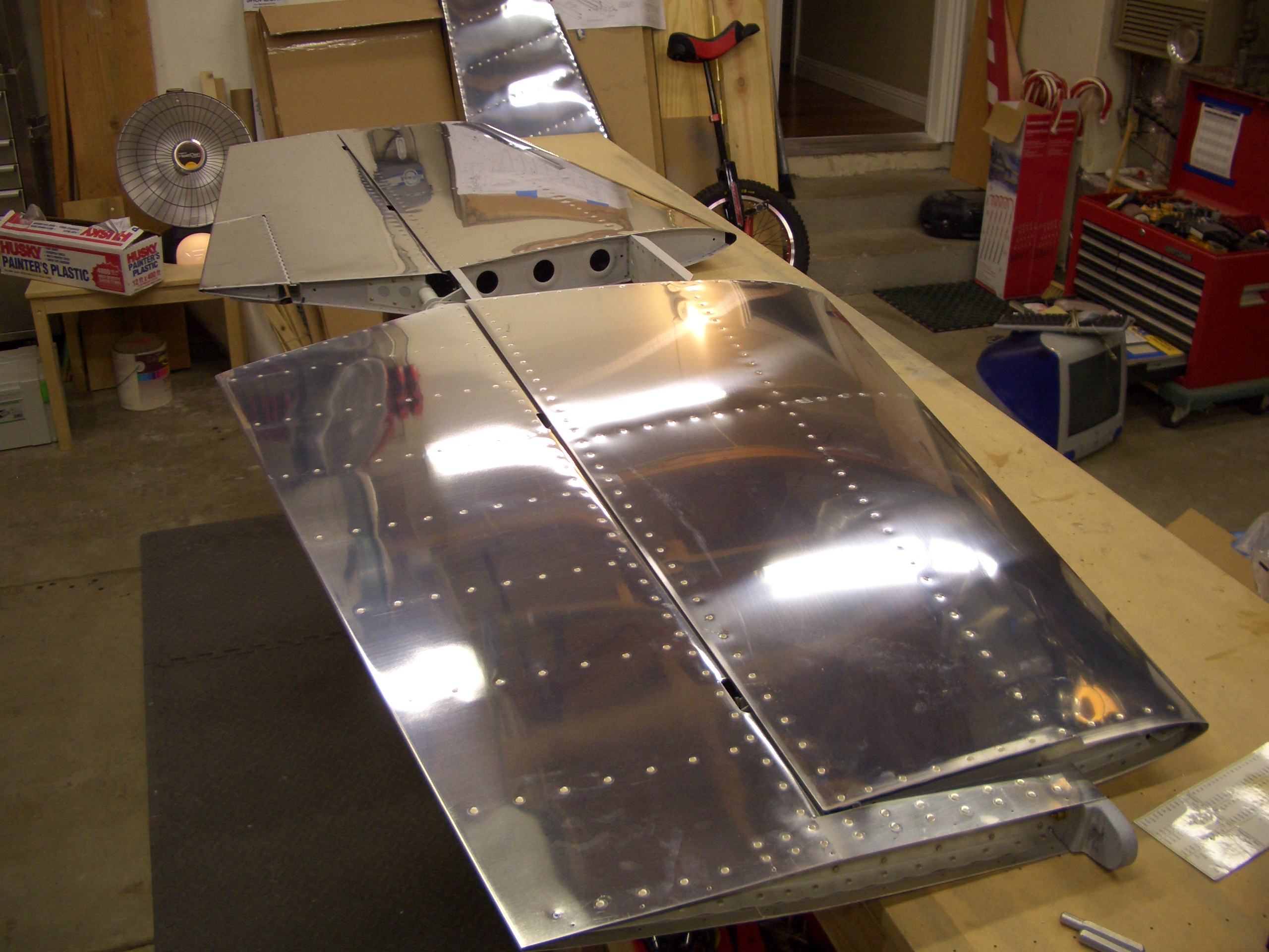
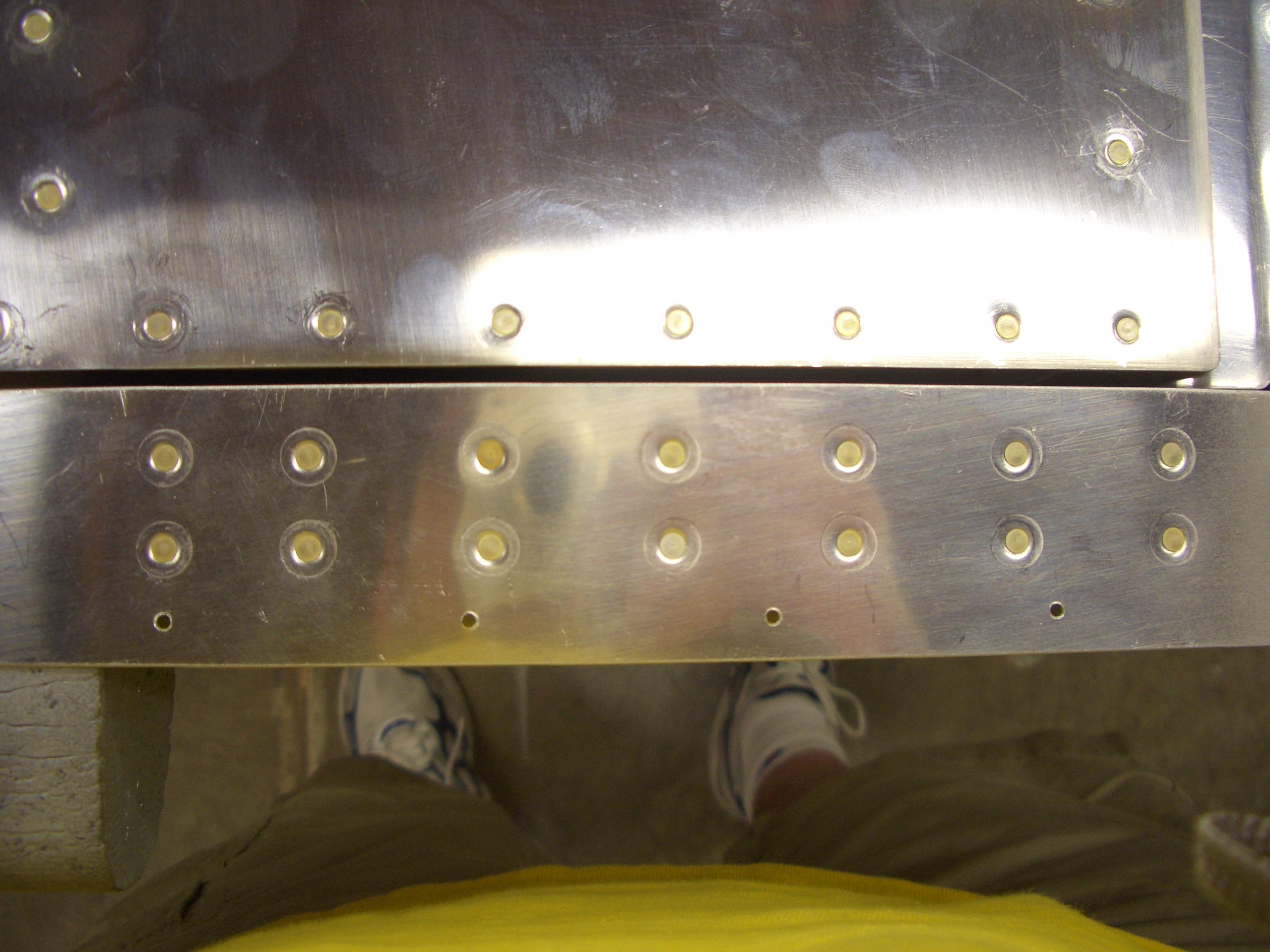
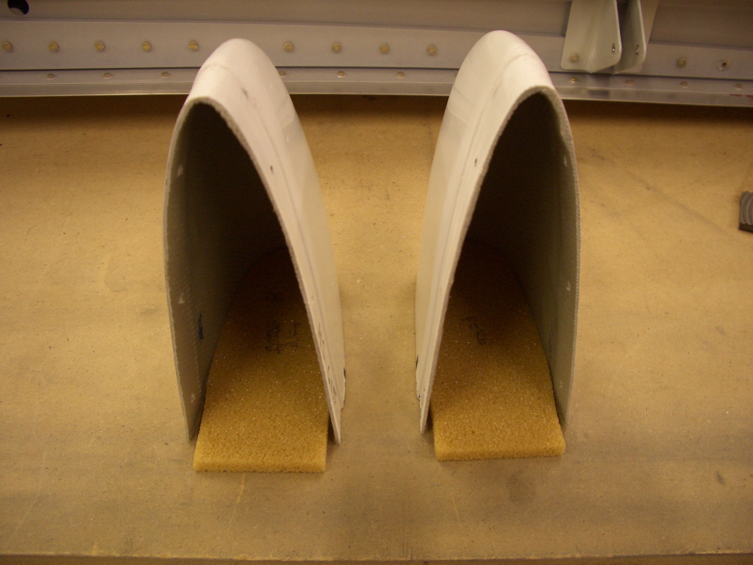
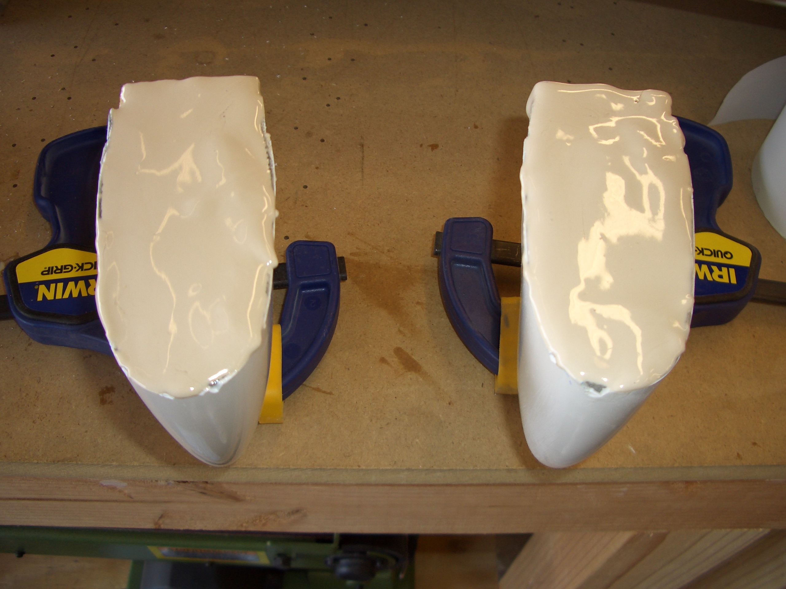
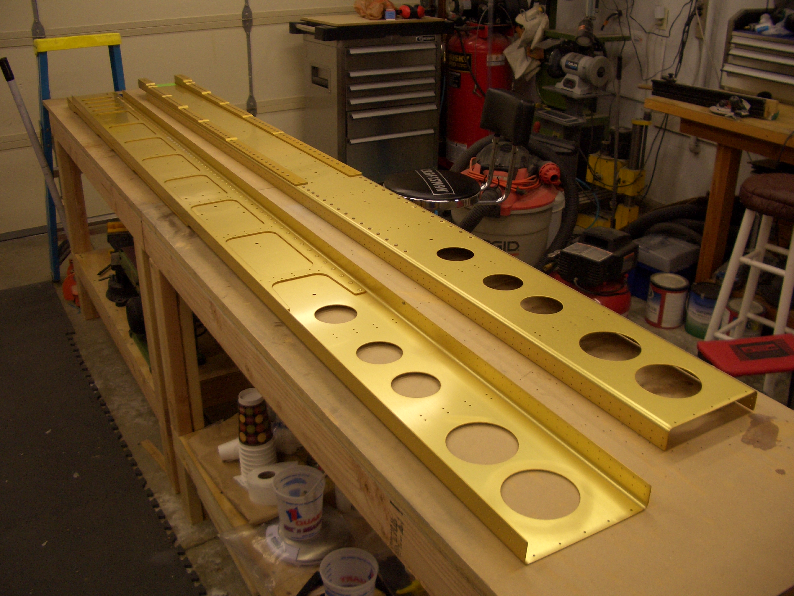
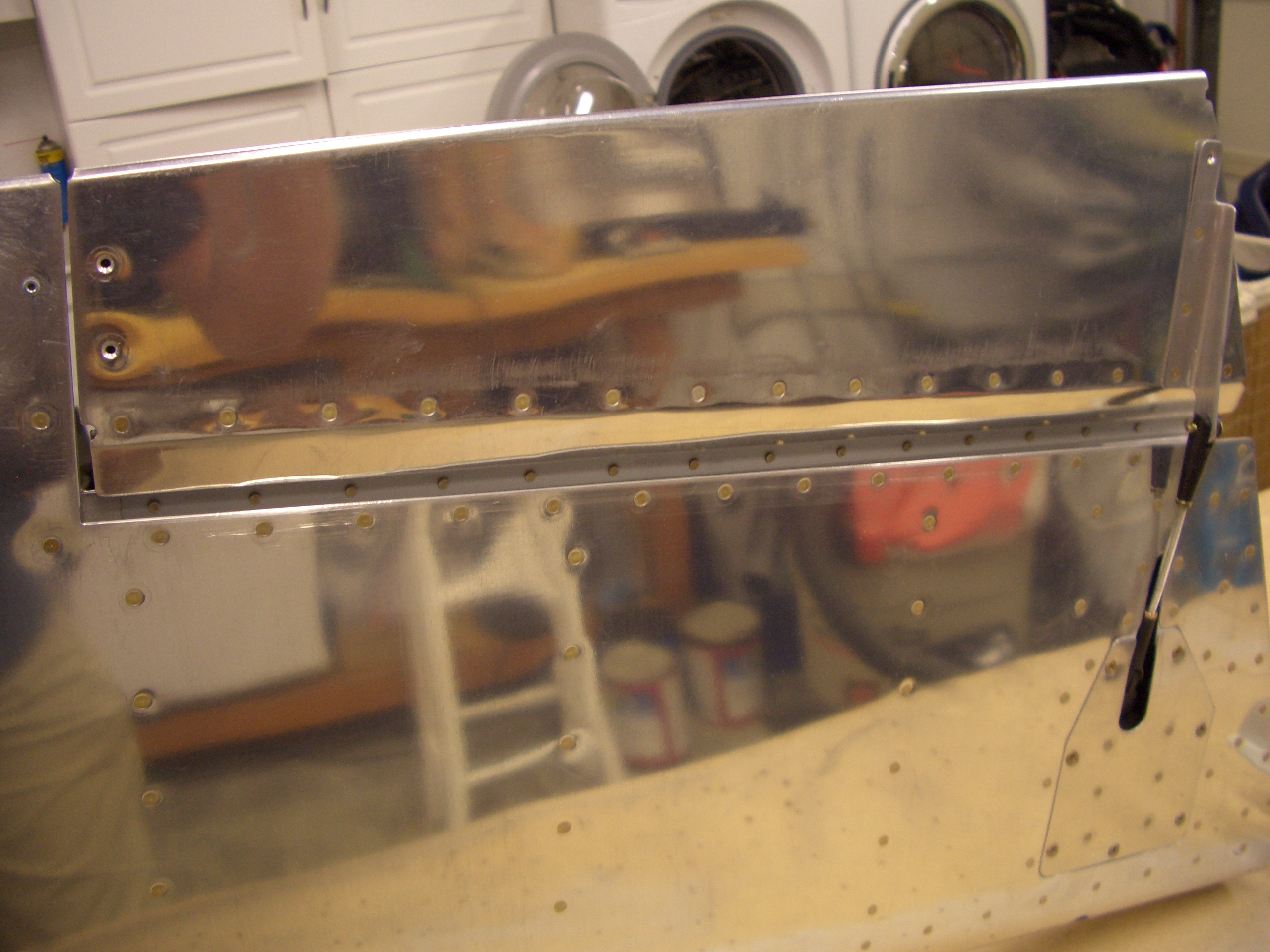
Next I got started on fitting the elevators to the horizontal stabilizer.  The horizontal stabilizer skin needs to be trimmed a bit to allow the elevator counterweights to clear, so I marked and trimmed the extra off.


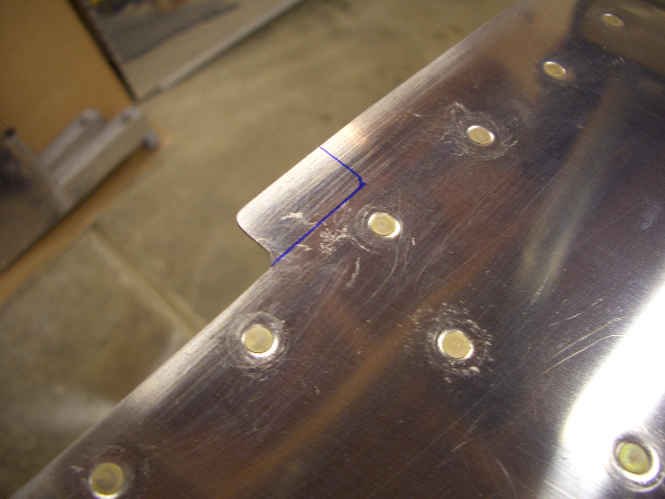
The lower portion of the rear spar flange also has to be trimmed to clear the elevator horns.  This is tricky because you really don’t want to nick the spar reinforcing bars just behind the flange.  I stuck an extra strip of 0.032″ aluminum under there when using the dremel tool to give me a little insurance.  Worked great; clean cut and no nicks on the reinforcing bars.


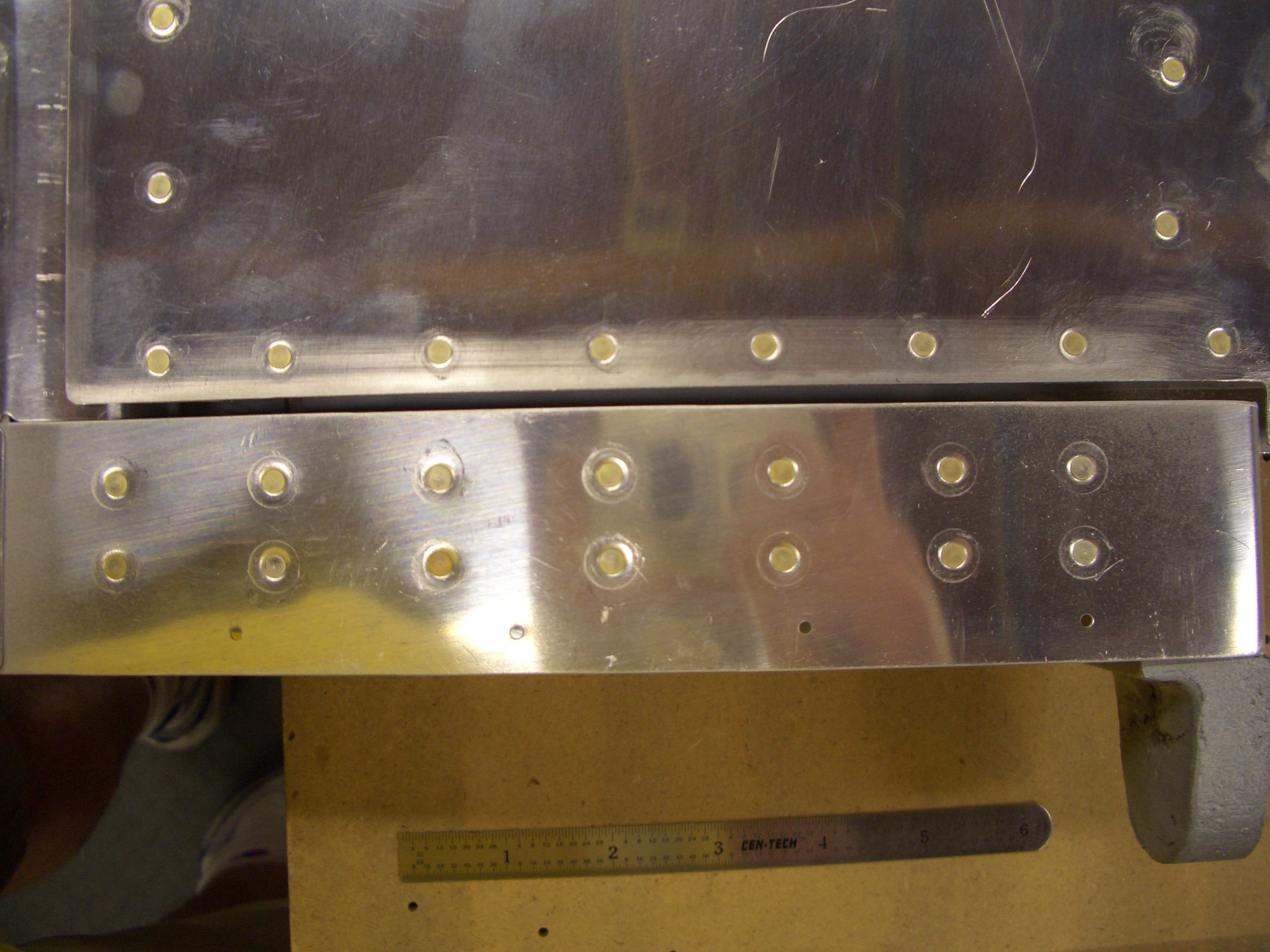
Here are both elevators fit to the horizontal stabilizer.  It looks so cool to finally see some big parts taking shape.

Trim Tab Rib

I fabricated the inboard trim tab rib.  Just like the outboard one, it took two tries before I was happy with the fit.  It’s easy enough to make the paper template accurate, but it takes a bit of practice to determine where to start the bend so that it winds up in the right spot.

Elevator Leading Edges and Trim Tab

I did a little fine tuning of the leading edges and installed the pop rivets.  I also installed the bearings into both elevators.  Here’s one of them (I don’t know which), but they all look about the same.  Basically, you screw these in until the center of the bearing is 13/16″ away from the spar face.  It’s not hard to be precise since one too many or one too few half turns is obviously off of 13/16″


Here’s another one.  This is the inboard bearing (the spar is wider at this point since all of the empennage surfaces taper as they move from the root to the tip).  Overall, I’m pretty happy with how the rolled leading edges turned out.  There is no puckering between the rivets as I’ve heard a number of builders complain about.  You really want to get the edges to lie flat against each other when the holes line up.  Also, putting a small roll in the top edge really helps.  I purchased the Cleaveland Tools edge rolling tool, and I’m really happy with it.


Now that I have the trim tab mounted and I’m happy with the alignment, I cut off the inboard ears in line with the inboard edge of the elevator.  I still have to fabricate a small rib to fit in here.


I also opened up the gap between the trim tab and elevator to 2/32″.  Van’s specifies the minimum gap as 3/32″, but that’s with folded ends and rivets that could conceivably interfere if something ever moved or flexed.  Since I’m using ribs here, nothing could move to decrease the clearance (There actually is a small amount of side to side play in the hinge, but the 2/32″ clearance is with the trim tab pushed as close to the elevator as possible.  The actual clearance varies from 2/32″ to almost 3/32″).  Even if hinge wear theoretically allows greater play at some point in the future, I could always increase the clearance by filing these edges back a little further (definitely not an option with the folded ends).


Here’s another shot of the elevator rib.  This picture makes it look like there’s a gap on the top edge, but the rivets will pull this down flush.


Here’s the second rib I fabricated for the outboard end of the trim tab.  The first was way off, but this fits perfectly.  I still need to dimple all of this which is why the little ear on the left isn’t sitting flat.  It was a little more work to make the ribs have these little ears to tie into the spar, but I think it’s well worth it to reduce the potential for flex and cracking.

Rolled Elevator Leading Edges

My buddy Andre stopped by tonight to help me roll the leading edges of the elevators.  They turned out better than the rudder, but this is still a pretty non-precision part of the construction.  My hands are killing me after this, so I’m done for the night.

Elevator Trim Tab

I drilled the forward part of the hinge to the elevator.  The clearance between the elevator and trim tab (below my thumb) is intentionally too tight right now.  I’ll file this back to the recommended minimum clearance of 3/32″.


Since I’m deviating from the plans and cut off the ears on the elevator and trim tab that are normally folded over to close off the end, I started trying to fabricate the ribs that will be used instead.  Here’s the rib that will fit into the end of the elevator.


And here it is installed.  Luckily, the first one I made fit really well.  I tried making one for the end of the trim tab, but that will need to be remade.  Fortunately by doing it this way, if you screw up, you’re only wasting a few cents on aluminum instead of a large part that requires an order from Van’s to replace.

Elevator Trim Tab

I back-riveted the row of rivets attaching the trim tab spar to the bottom of the trim tab.  I also back riveted the trim tab horn on.  I left out the rivets along the edge on each end so that the rib I’ll be fabricating can rivet through that as well.


I used a long piece of aluminum angle to ensure the trailing edge of the trim tab aligns with the trailing edge of the elevator (and ensured the inboard edges are aligned).

Elevator Trim Tab

I worked all day today, but managed to make a little bit of progress on the elevator trim tab.  I positioned and drilled the hinge to the trim tab.


I attached the trim tab servo to get it out of the way.


I prepped and primed the parts for the trim tab.  I can’t start riveting these tonight since the spar is back-riveted onto the skin and that will make too much noise.

Left Elevator Riveted

I riveted the left elevator skin to the structure and bolted on the counterweight.


Here’s a shot of the complex intersections of the spar, counterweight rib, elevator skin and counterweight skin.  These rivets turned out even nicer than on the right elevator.


I did a little more prep on the trim tab as well.  Here are the holes in the trim tab spar, countersunk to accept the skin dimples.  These are countersunk because the trim tab hinge will mount flush to the underside of this flange.