Installed Parking Brake Cable

I installed the parking brake cable tonight.  The cable comes pretty much straight back from the panel and then turns up and is anchored to one of the angles that support the VP-X (seen in the lower right of the photo).  The cable then arcs across the cabin (anchored in the middle to forward top skin center rib).

The cable is then anchored to a piece of 0.063″ angle that is attached to the left subpanel rib.  The angle serves as a mounting point for the cable as well as a stop for the parking brake arm.  Here is the parking brake with the cable full forward which is the off position.

Here is the parking brake on the on position.

Here is how far out the parking brake knob comes with the parking brake on.

Riveted Side Skin and Roll Bar Support

My buddy Andre stopped by and we riveted the forward ends of the skins that wrap around the rear window.

We then riveted these support plates to the longerons and seat support bulkhead.  The beefy angles I modified yesterday are installed under here to transfer any roll-over loads into the rest of the structure.

The angles are also riveted to the front face of the bulkhead.  We managed to rivet all of the these without removing the latch or the microswitch by using the double offset rivet set.

We also riveted these angles to the front side of the bulkhead to support the canopy latch bellcrank.

Primed Forward Fuselage Components

I primed the subpanel and a bunch of fuselage components using the EkoPoxy primer.

While I had everything undone from the subpanel and forward ribs, I installed nutplates everywhere I’m using screws to attach things to the subpanel.  The ones along the bottom here are to attach adel clamps that support the wiring harness.

I also installed a few on the right rib to support the battery and essential bus blocks.  If I ever have to remove these or any of the adel clamps, it will be much if I don’t have to simultaneously get a wrench on the nut.

Cabin/Panel Area Riveting

I came out before work this morning and riveted the outer subpanel sections to the side bulkheads and the ribs.

I was able to use the straight set to shoot solid rivets in all of the holes tying these to the bulkheads.

The side subpanel sections are riveted to the forward ribs using only two flush head rivets to provide a flat space for the hinge bushing block to be installed.

Andre dropped by in the evening and we knocked out the forward and aft canopy decks.  There were only a few challenging rivets where there isn’t much room to buck, but we managed to get solid rivets in every hole without too much pain.  You can see on the other side that we also riveted the fresh air vent brackets to the side of the fuselage.

We also riveted the armrests.  There’s still some give to these, so I don’t want passengers to push down on them when getting out of the plane, but they’re way stronger than the stock Van’s design.

After Andre left, I finished pop-riveting the F-704 cap strips in place.

Misc Flap Related Tasks

I replaced six of the rivets on the flap motor support with flush head ones.  The ones at the top were rubbing on the canopy latch torque tube and I did the ones below just for aesthetics.

I also drilled a hole in the flap motor bearing and safety wired it to the tube.  The bearing rocks back and forth as the motor goes up and down, and if this comes loose, it can come completely unscrewed.

Painted Interior

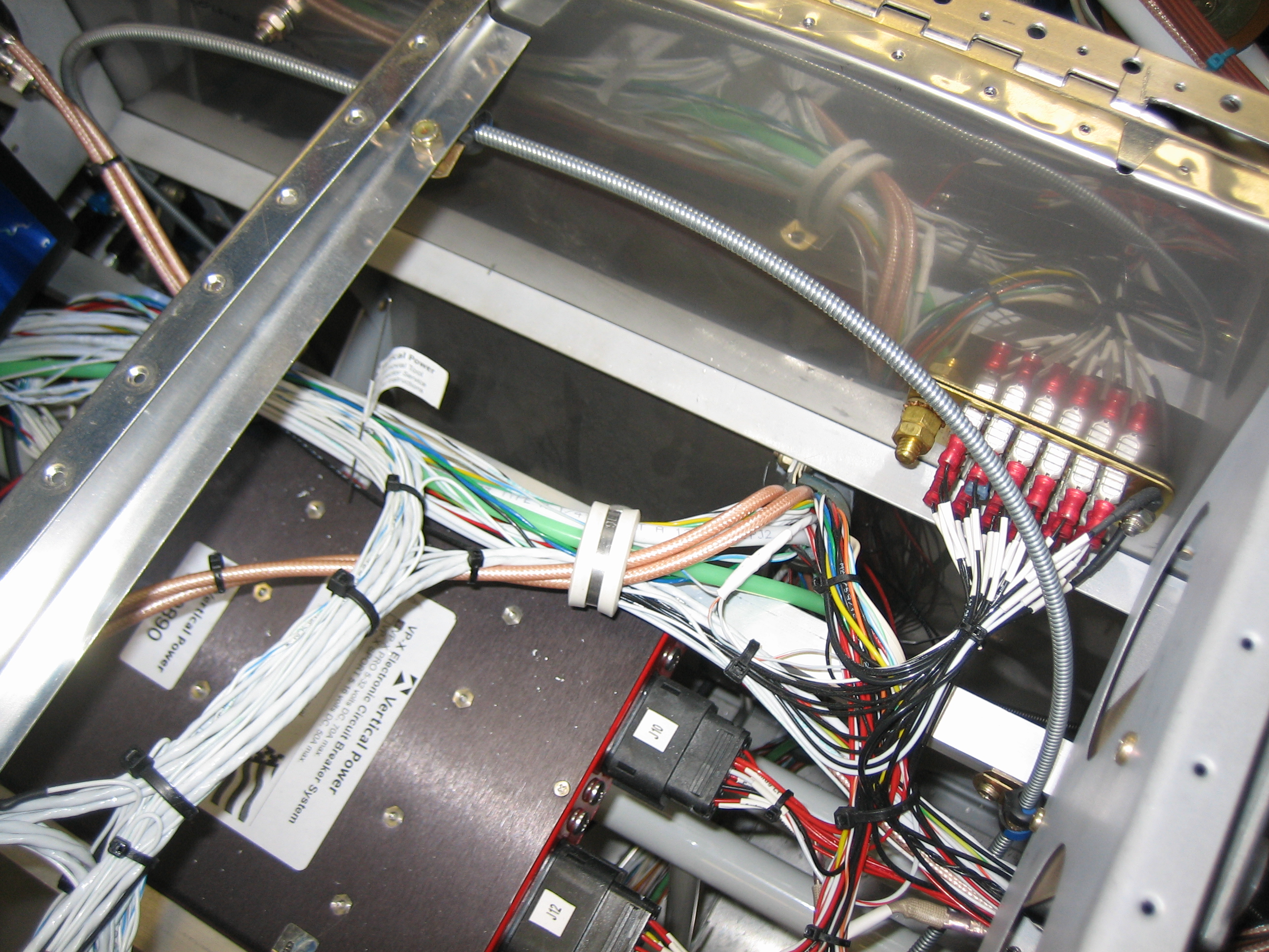
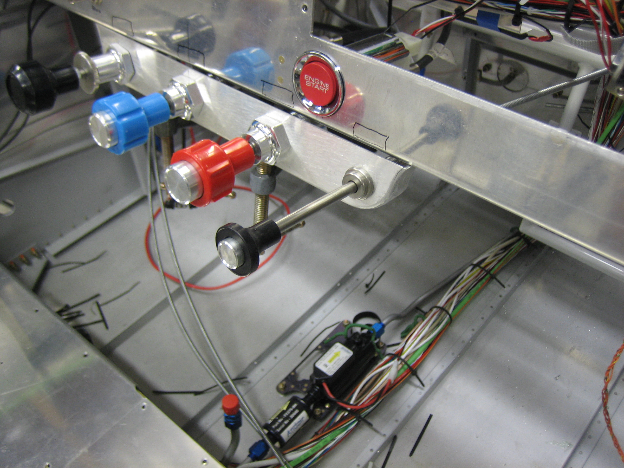
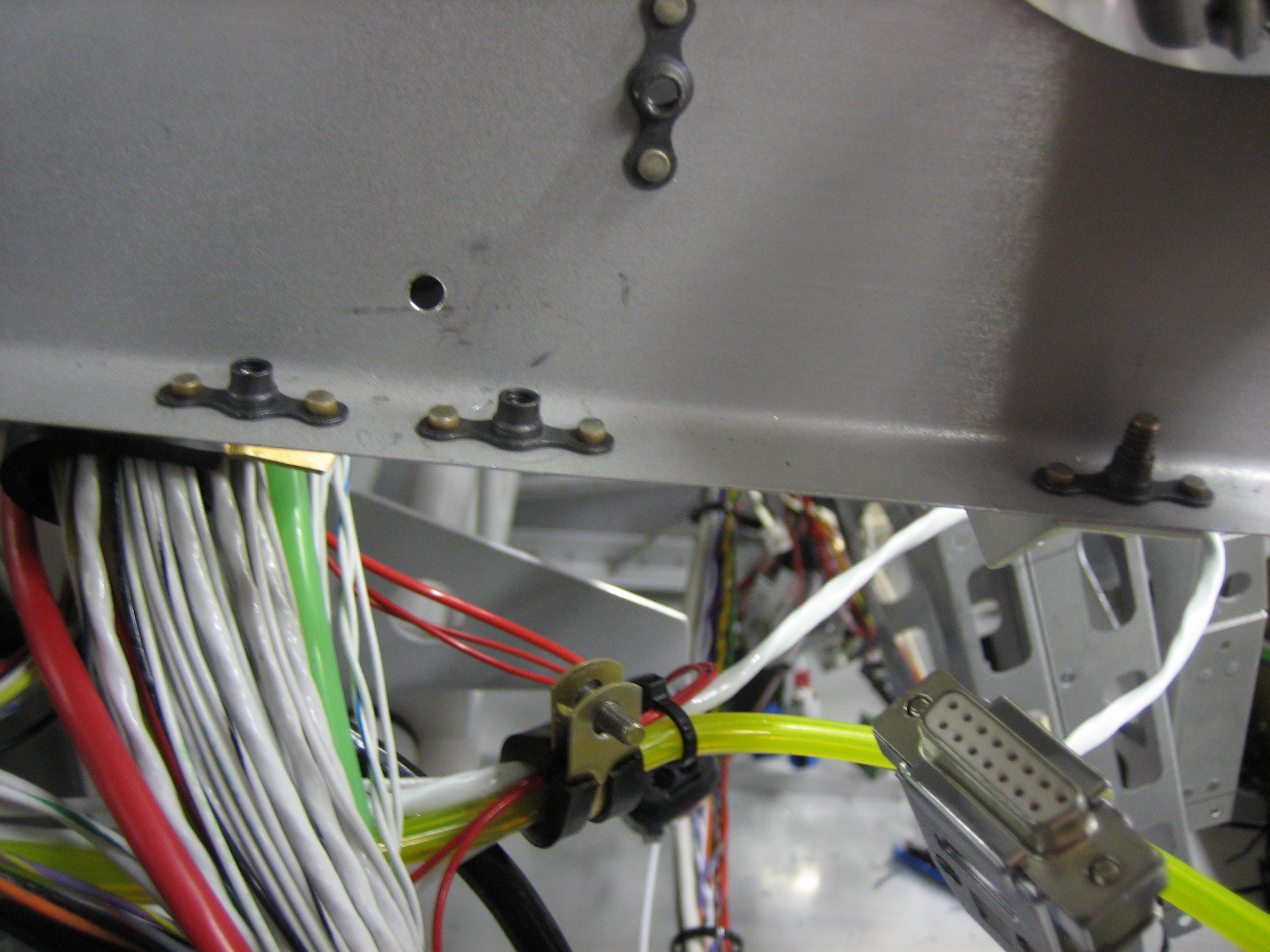
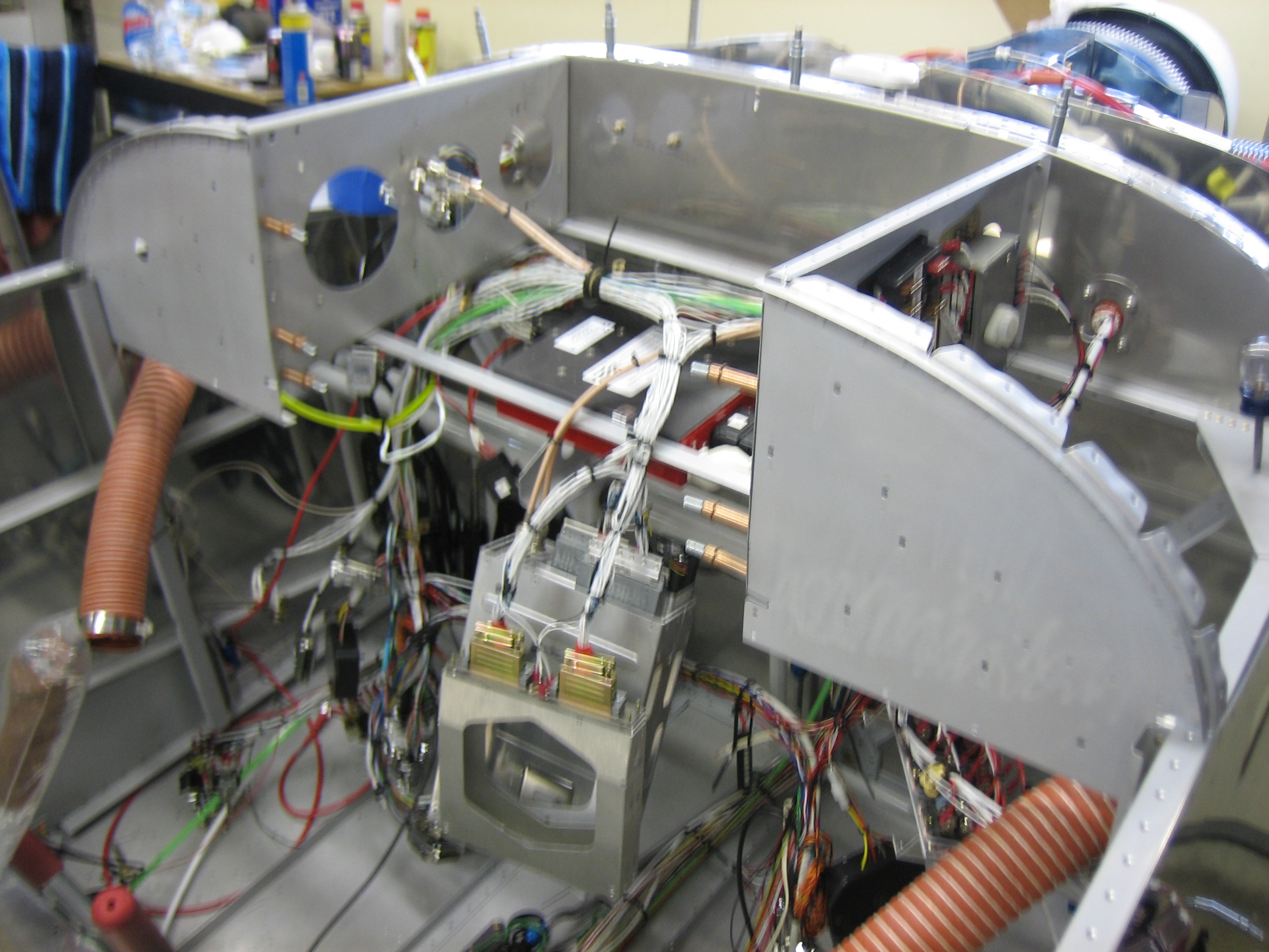
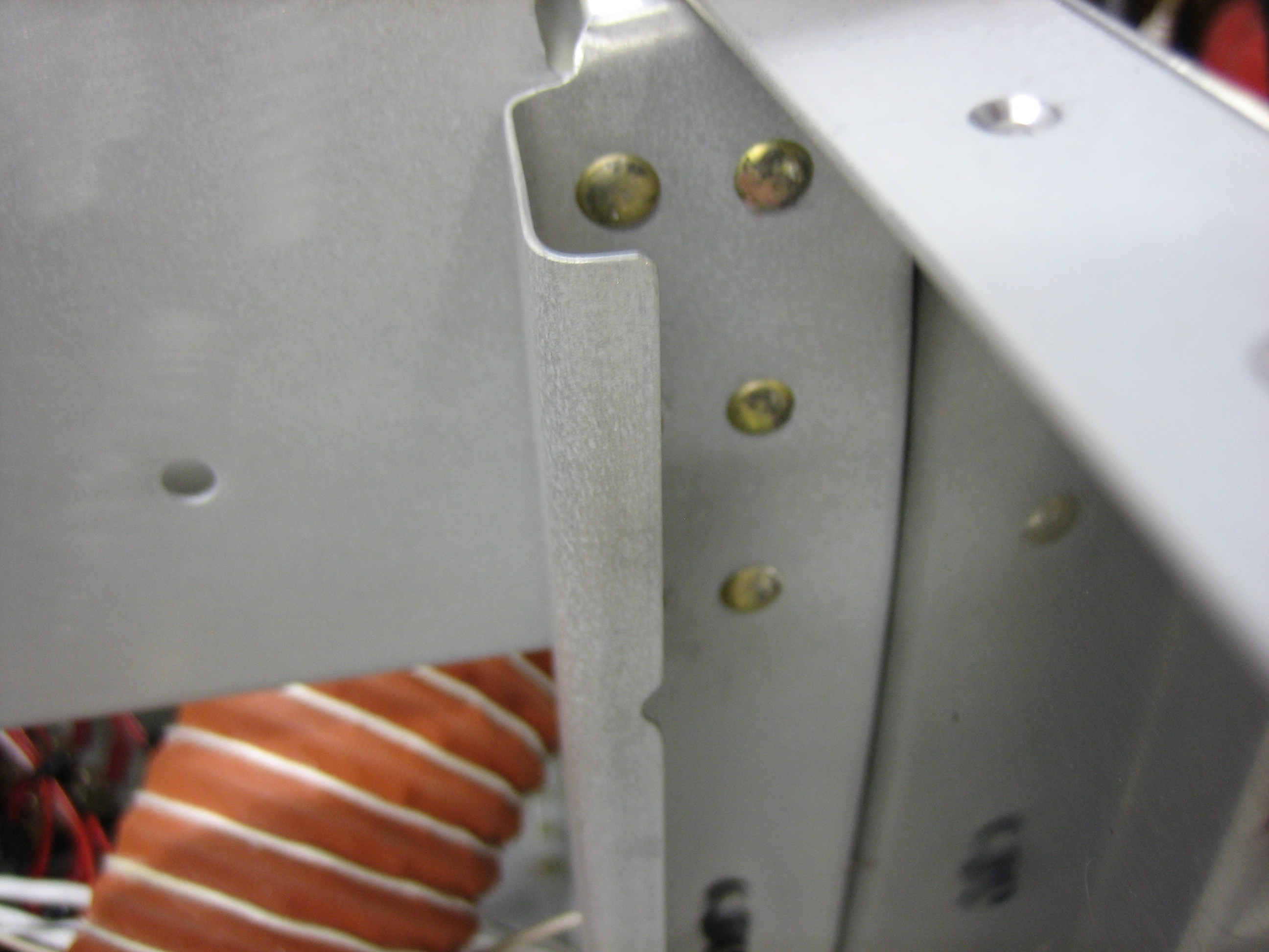
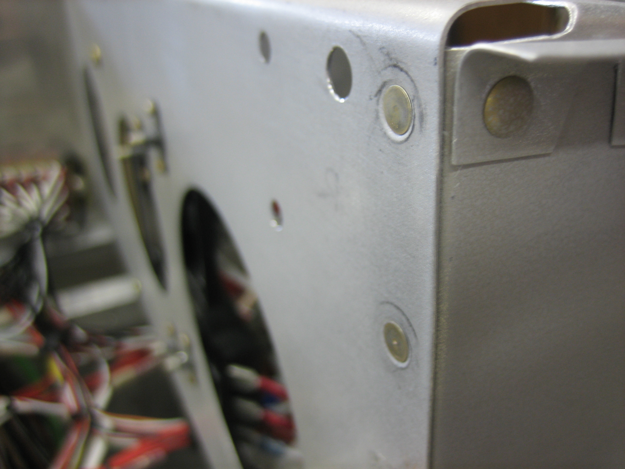
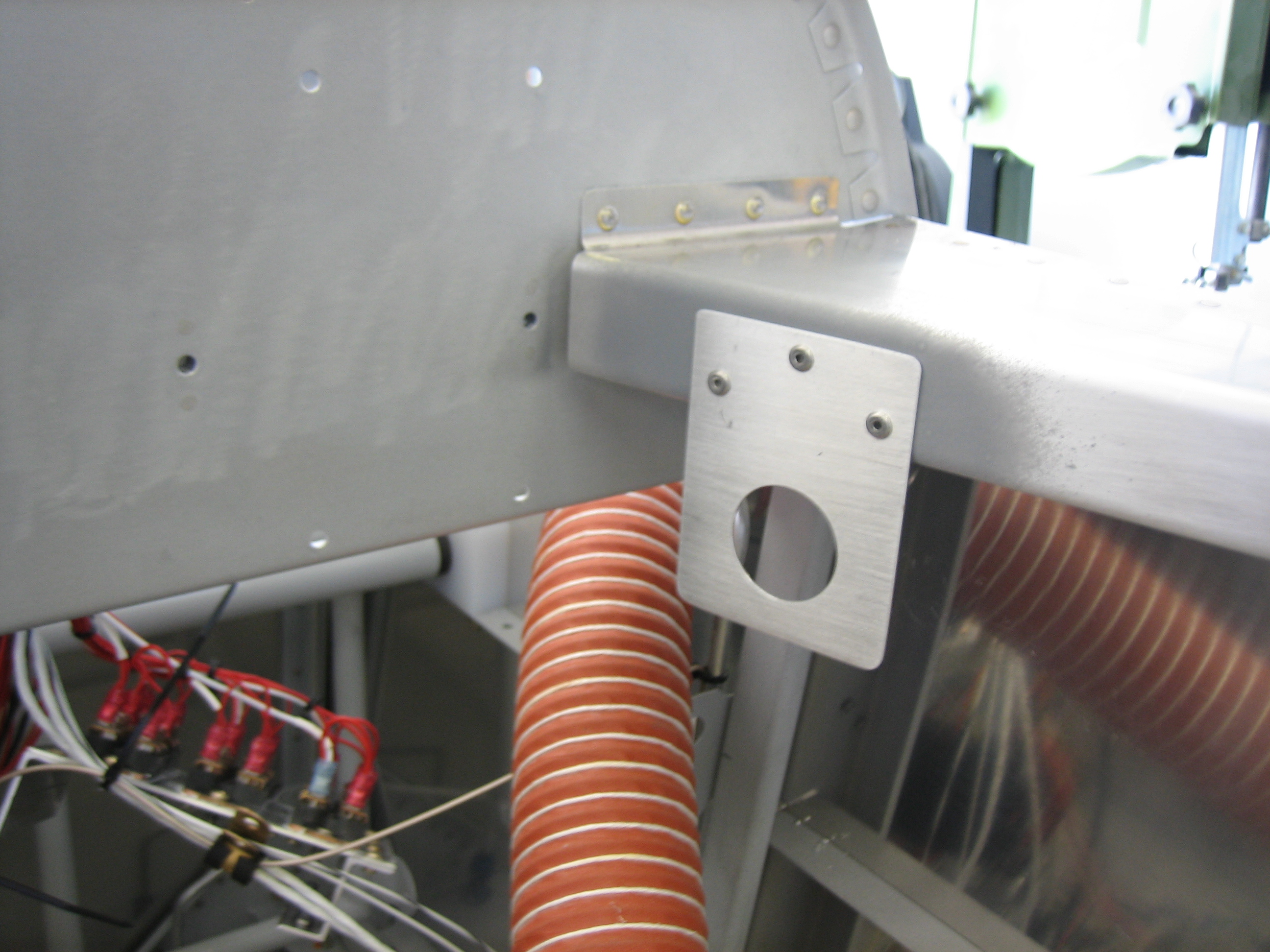
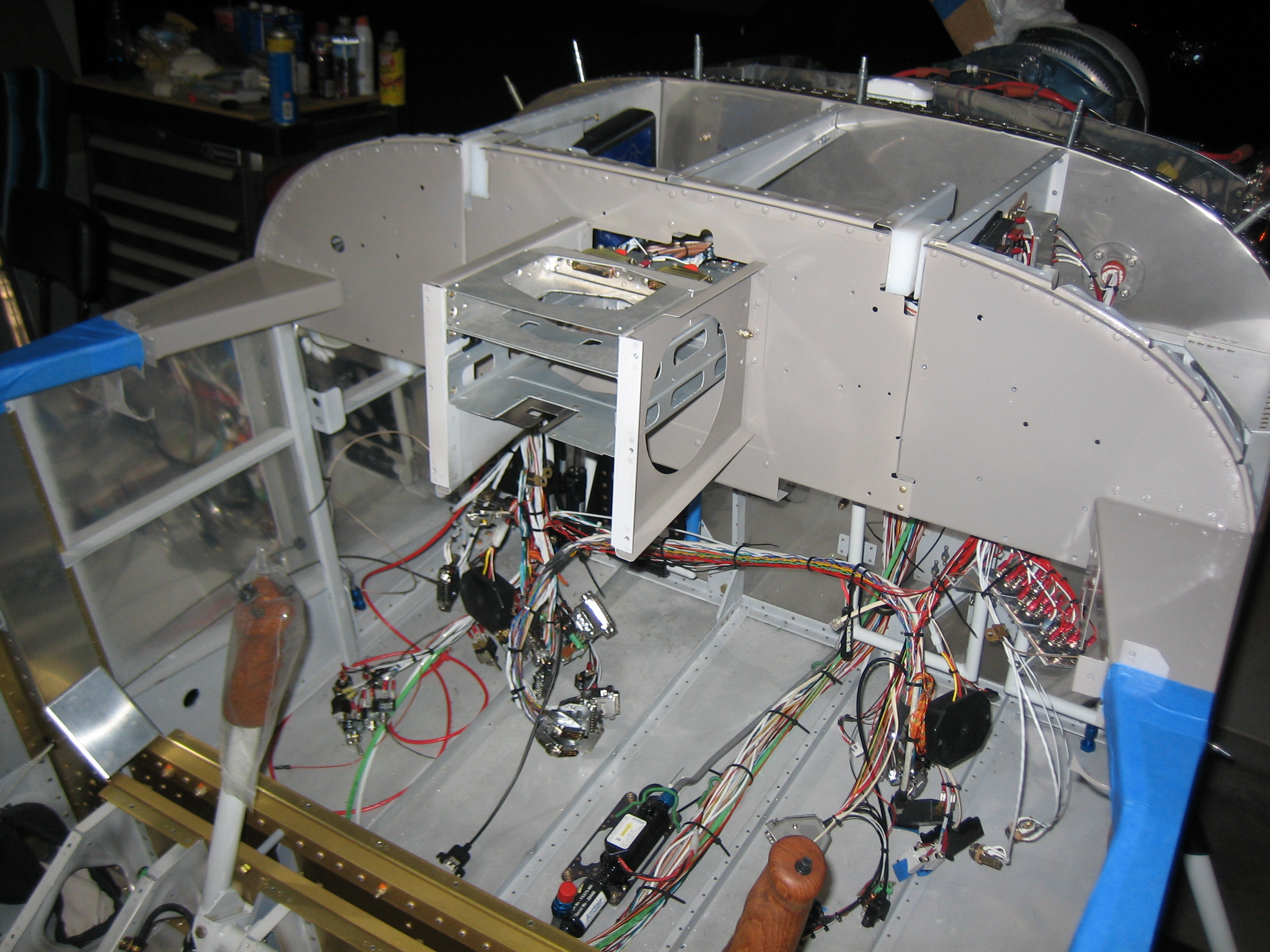
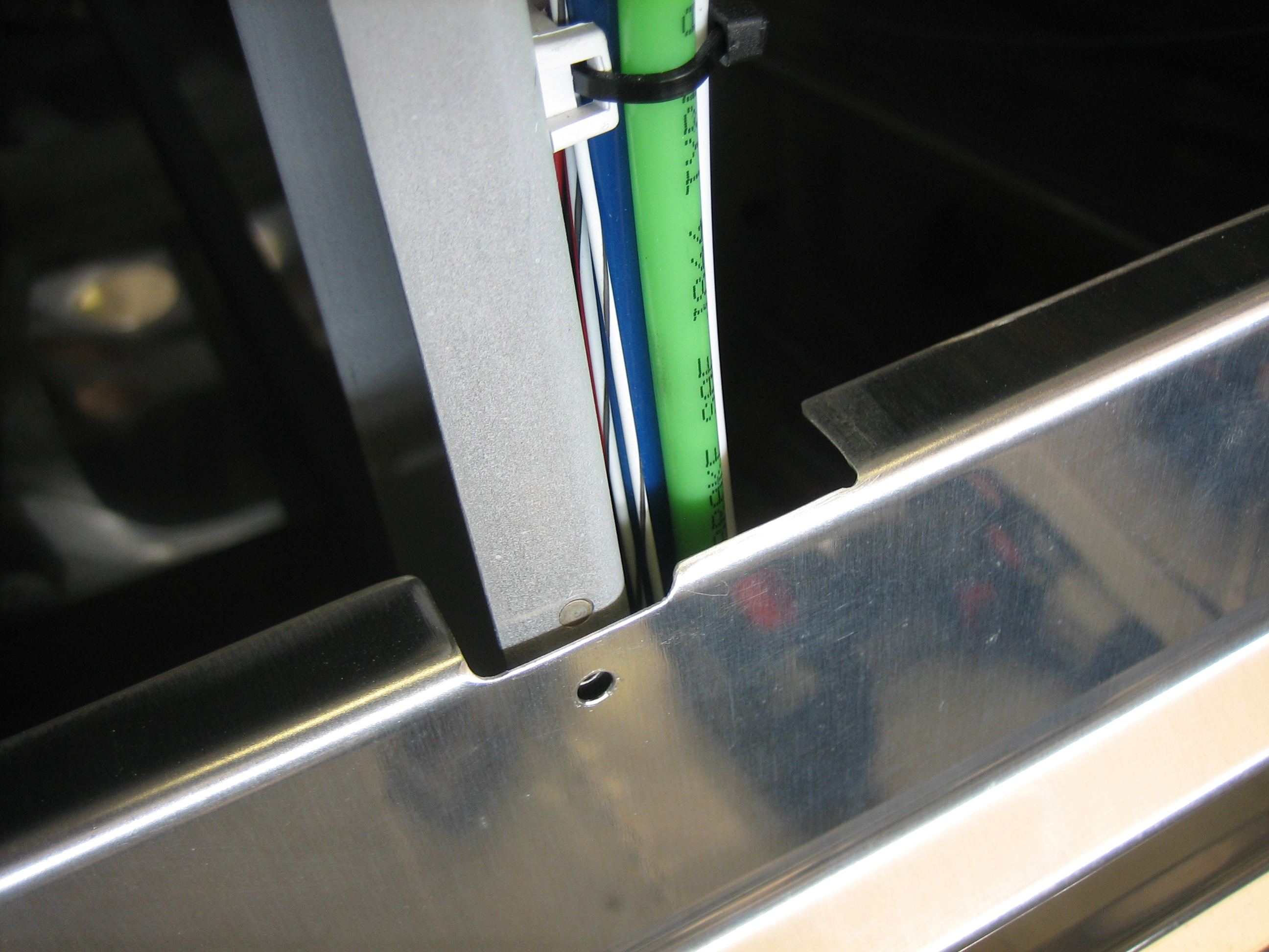
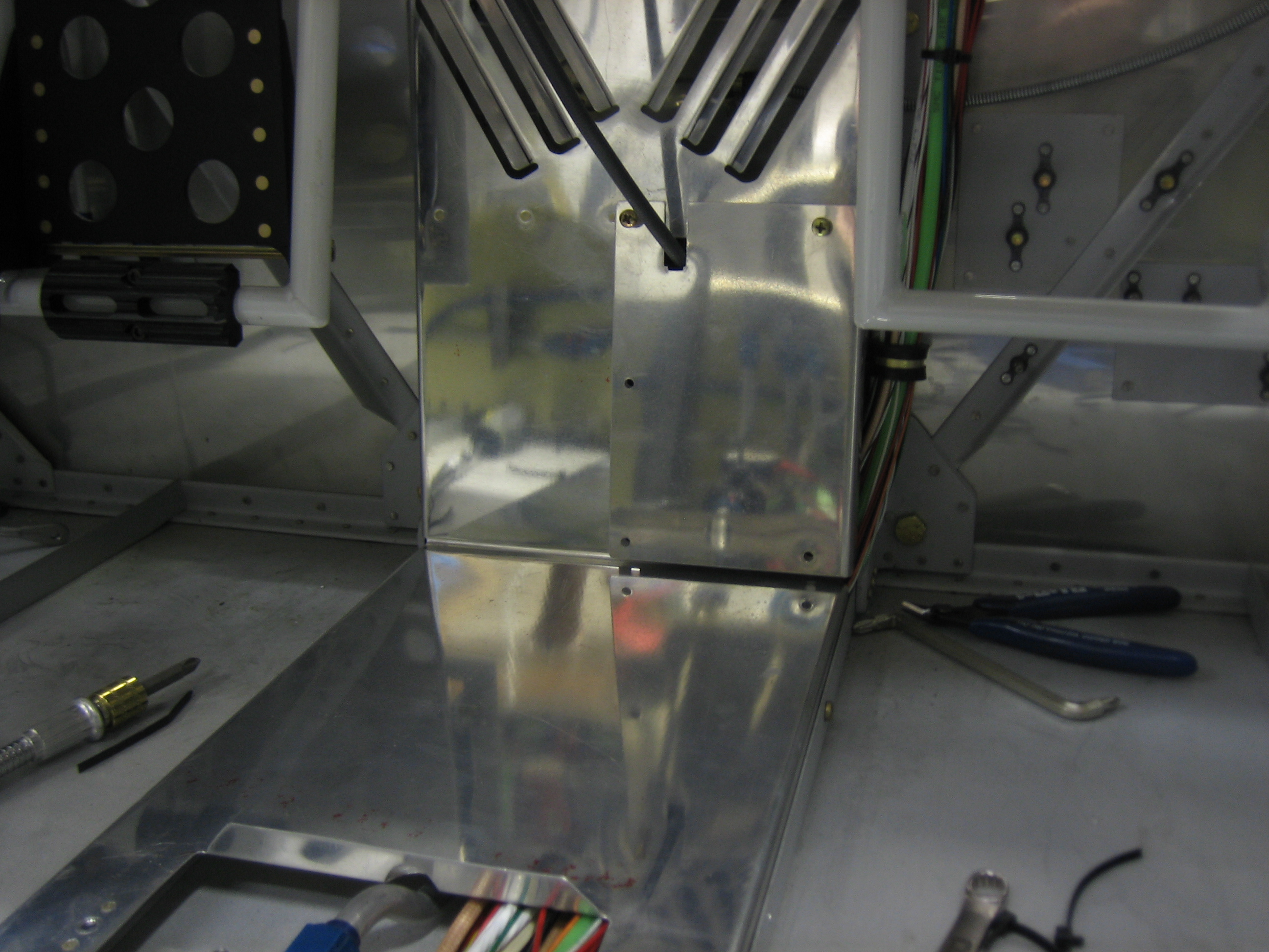
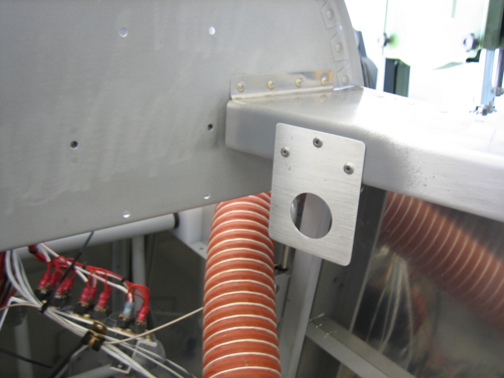
I added a small bracket to the right canopy deck between the panel and subpanel.  This will hold a cigarette lighter socket that can be used to charge devices.  I picked up a dual USB plug that I’ll likely leave in this most of the time.  This was really the only place I could find behind the panel that isn’t blocked by something.

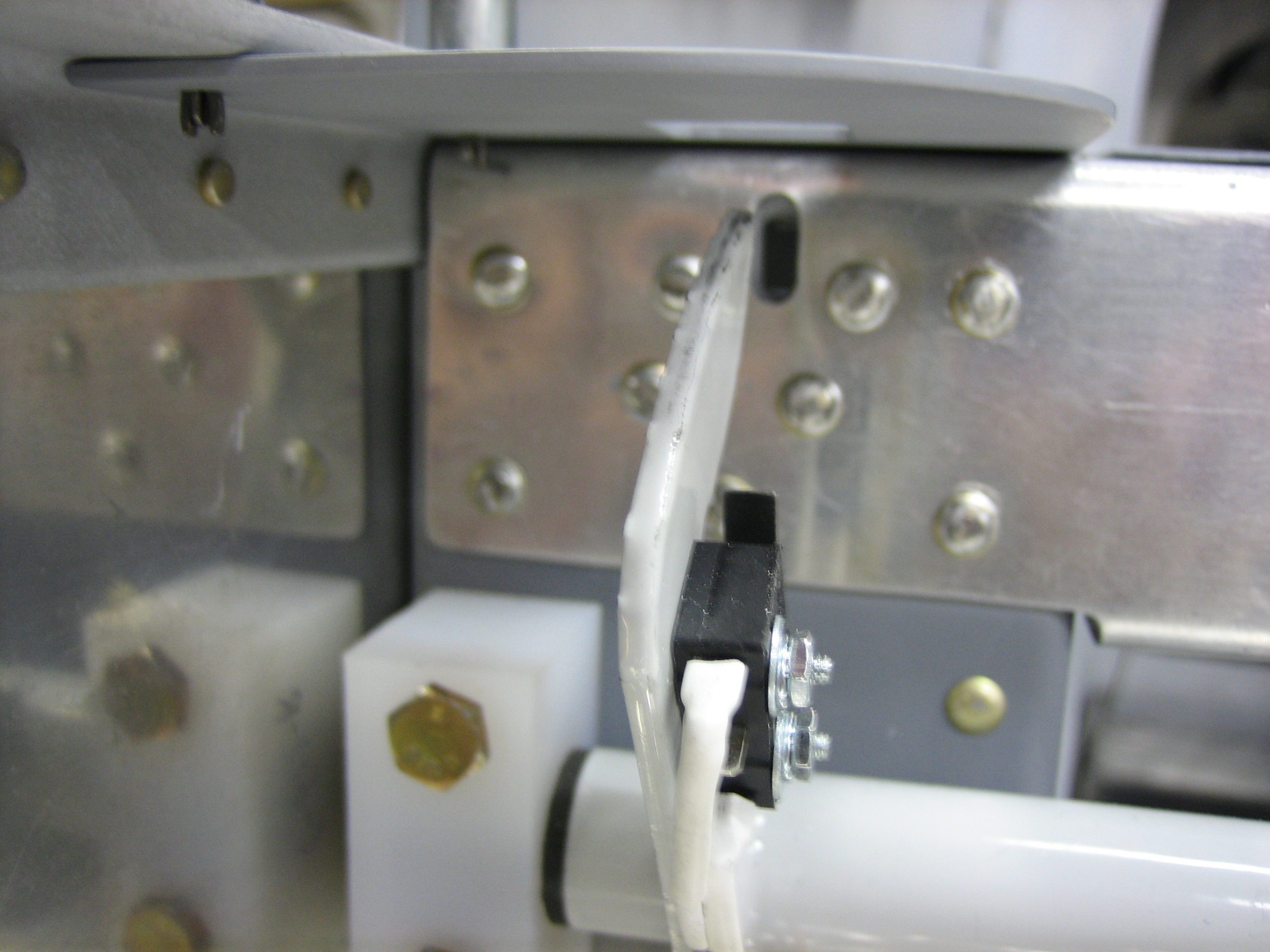
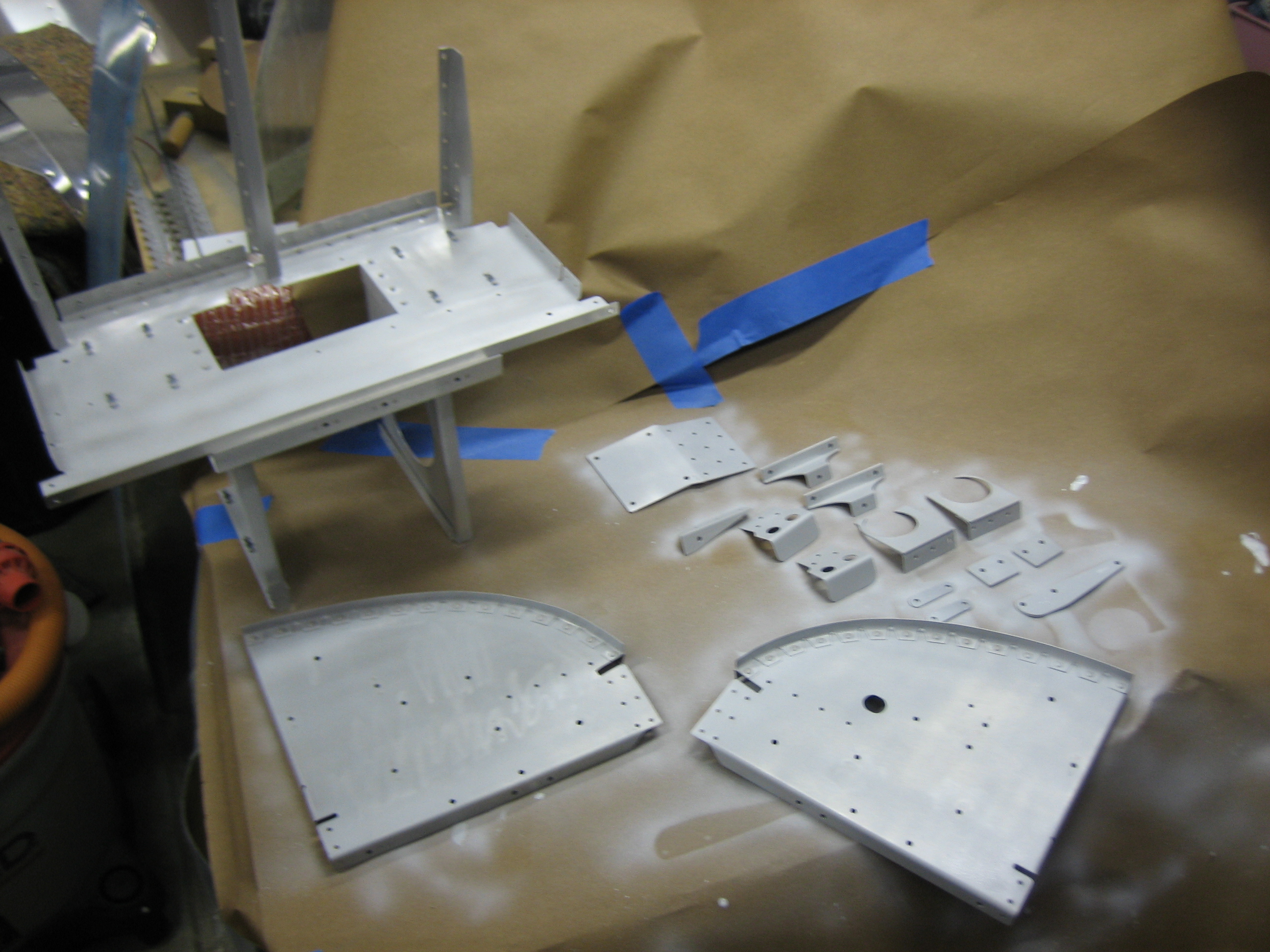
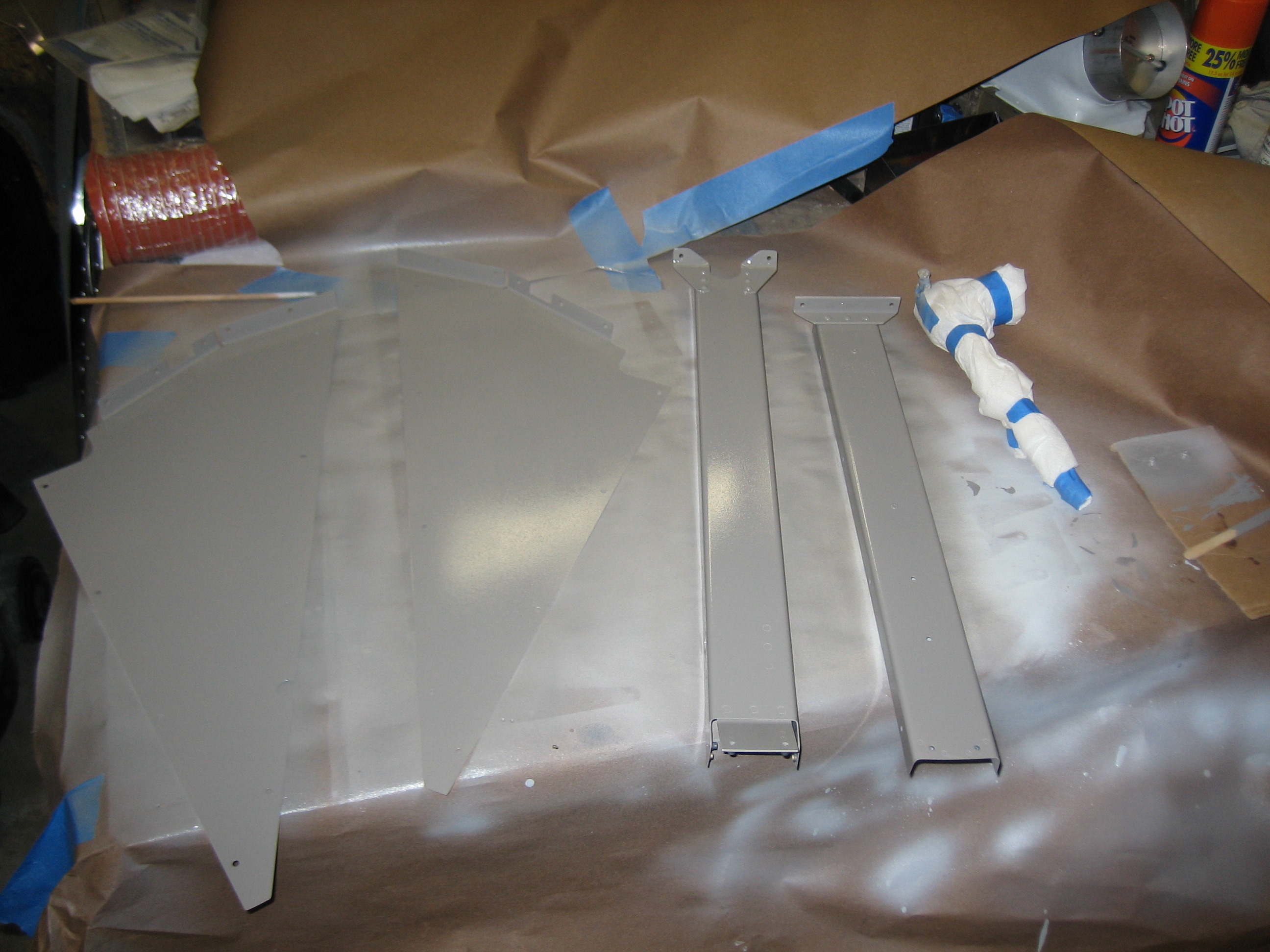
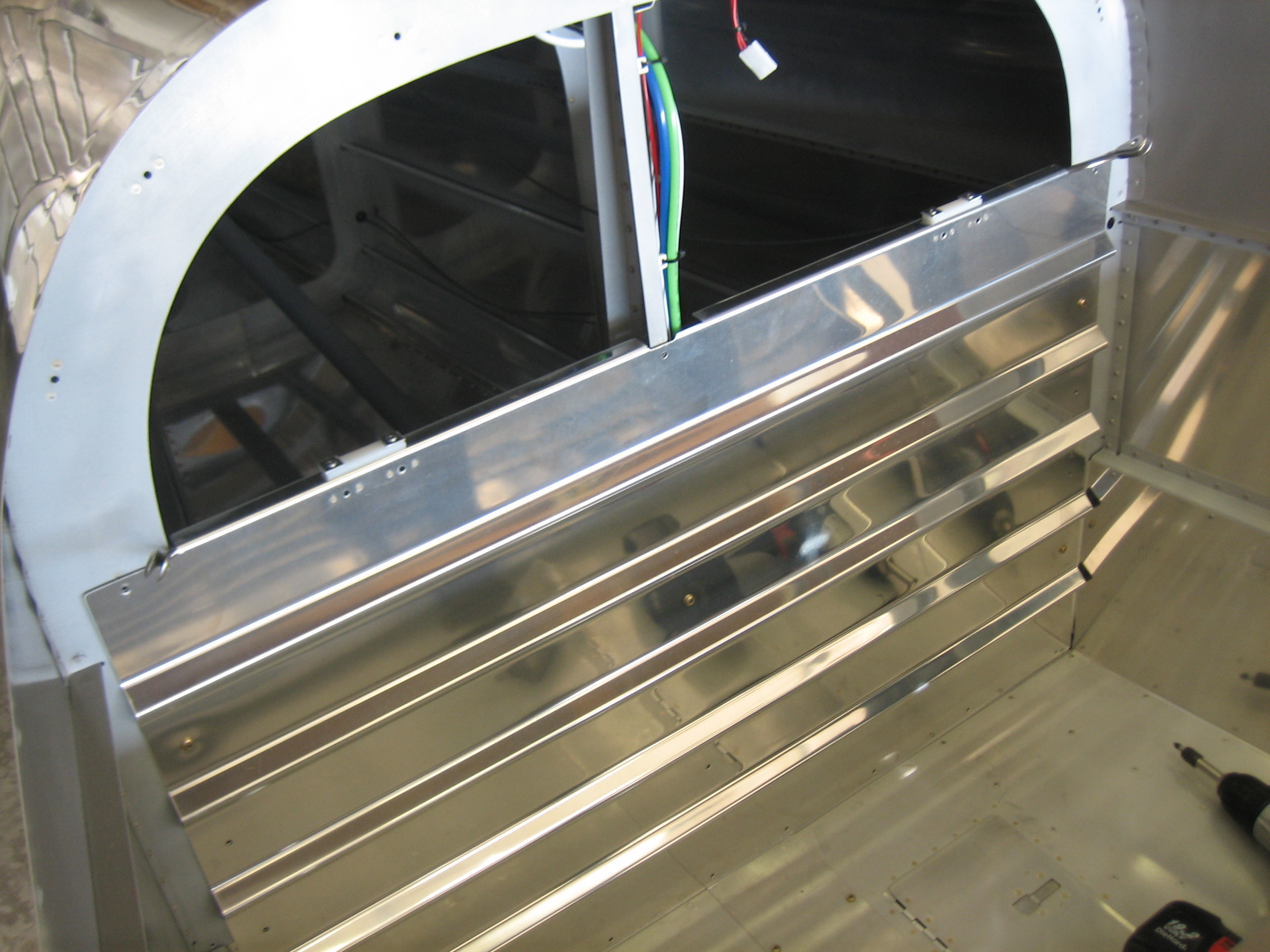
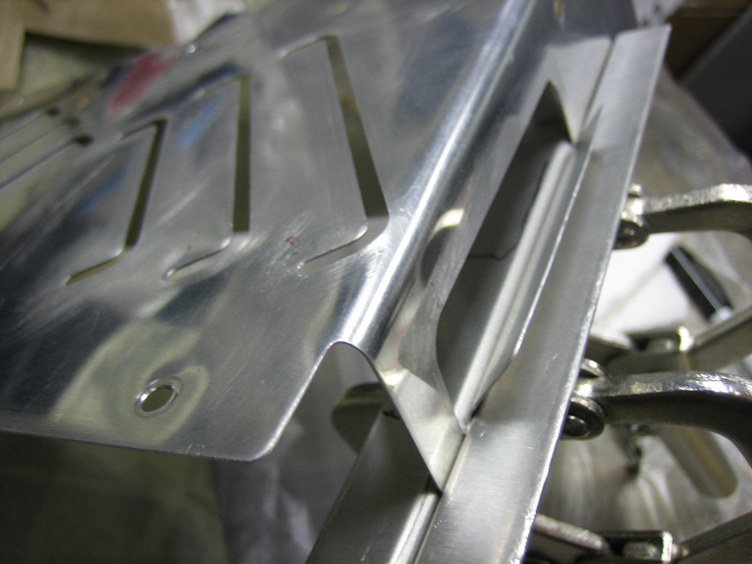
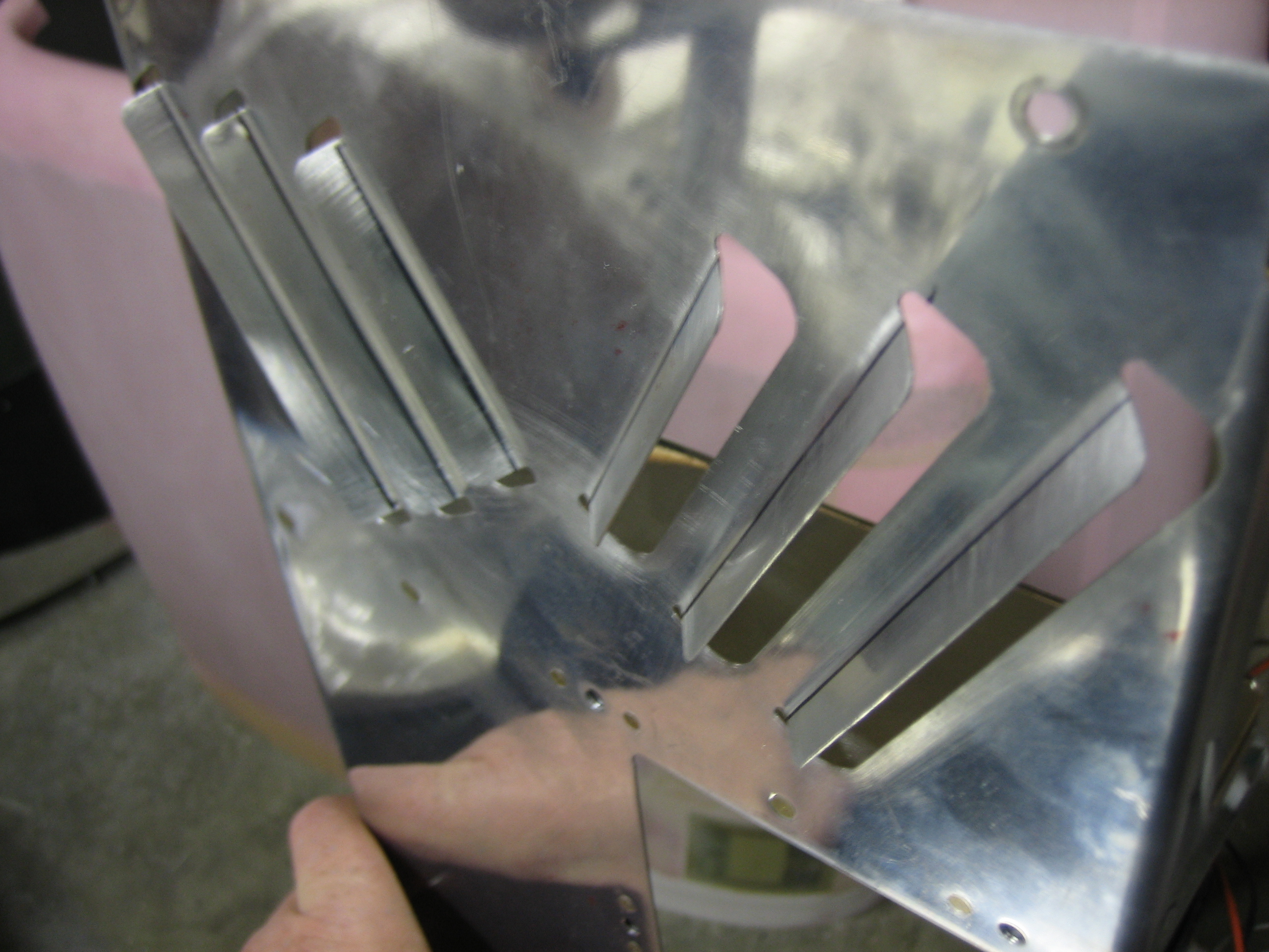
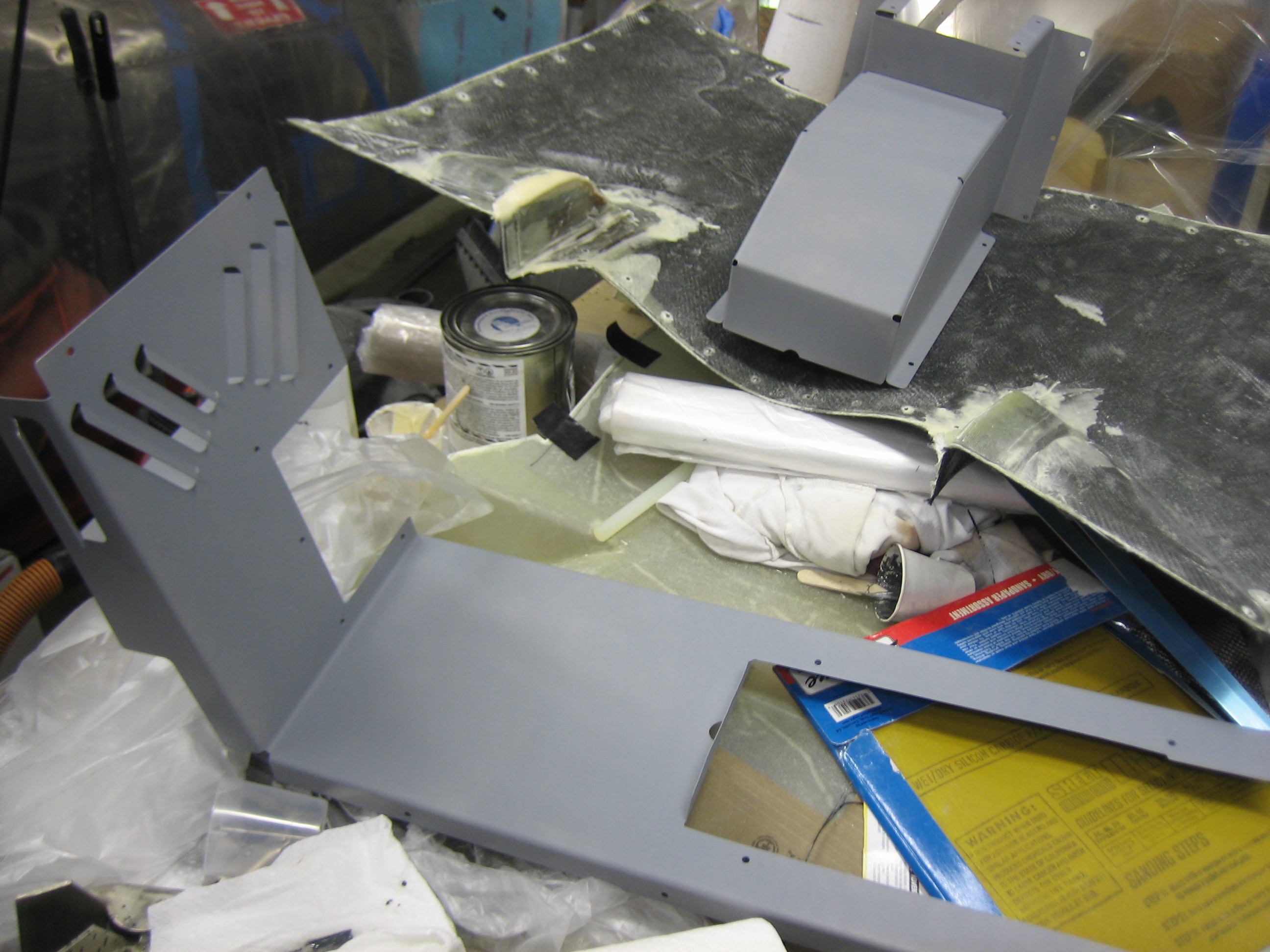
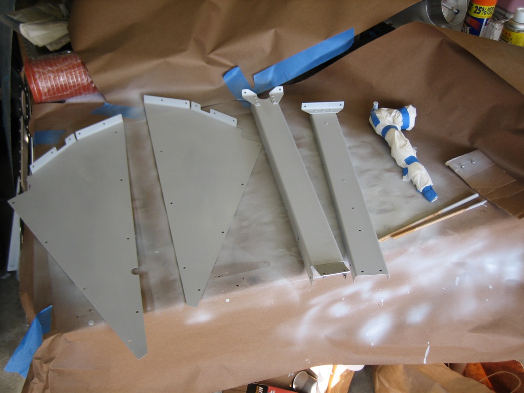
I primed all of the flap cover pieces.  On the right is the flap motor wrapped up with paper towels.  I primed the head of the bolt that will be visible on the outside of the flap motor support.  On the far right is a piece of cardboard with a couple of #6 screws that are used to attach the flap position sensor.  I’m painting them as well so they blend in.

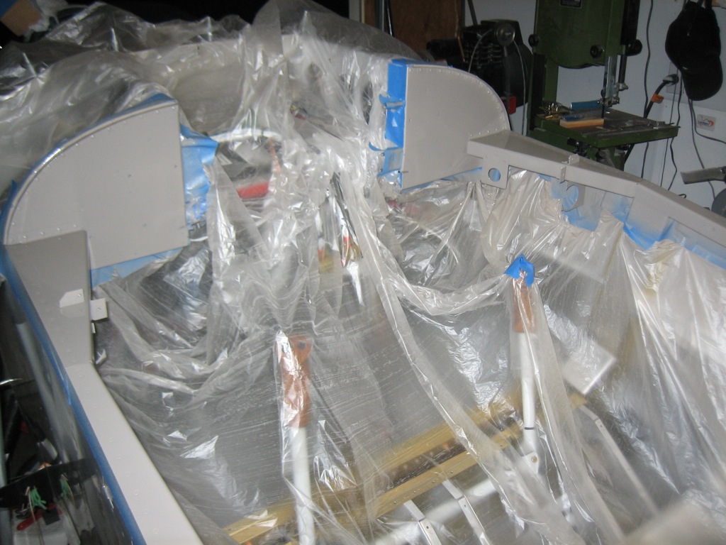
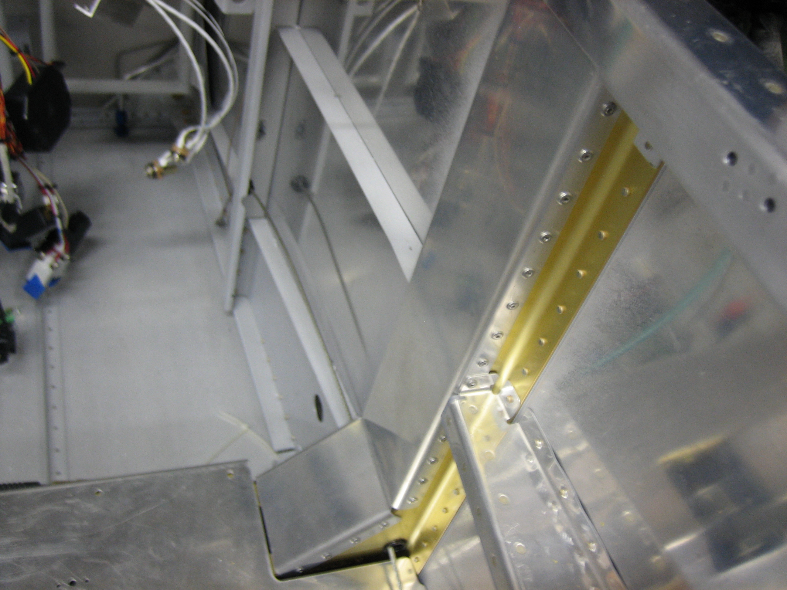
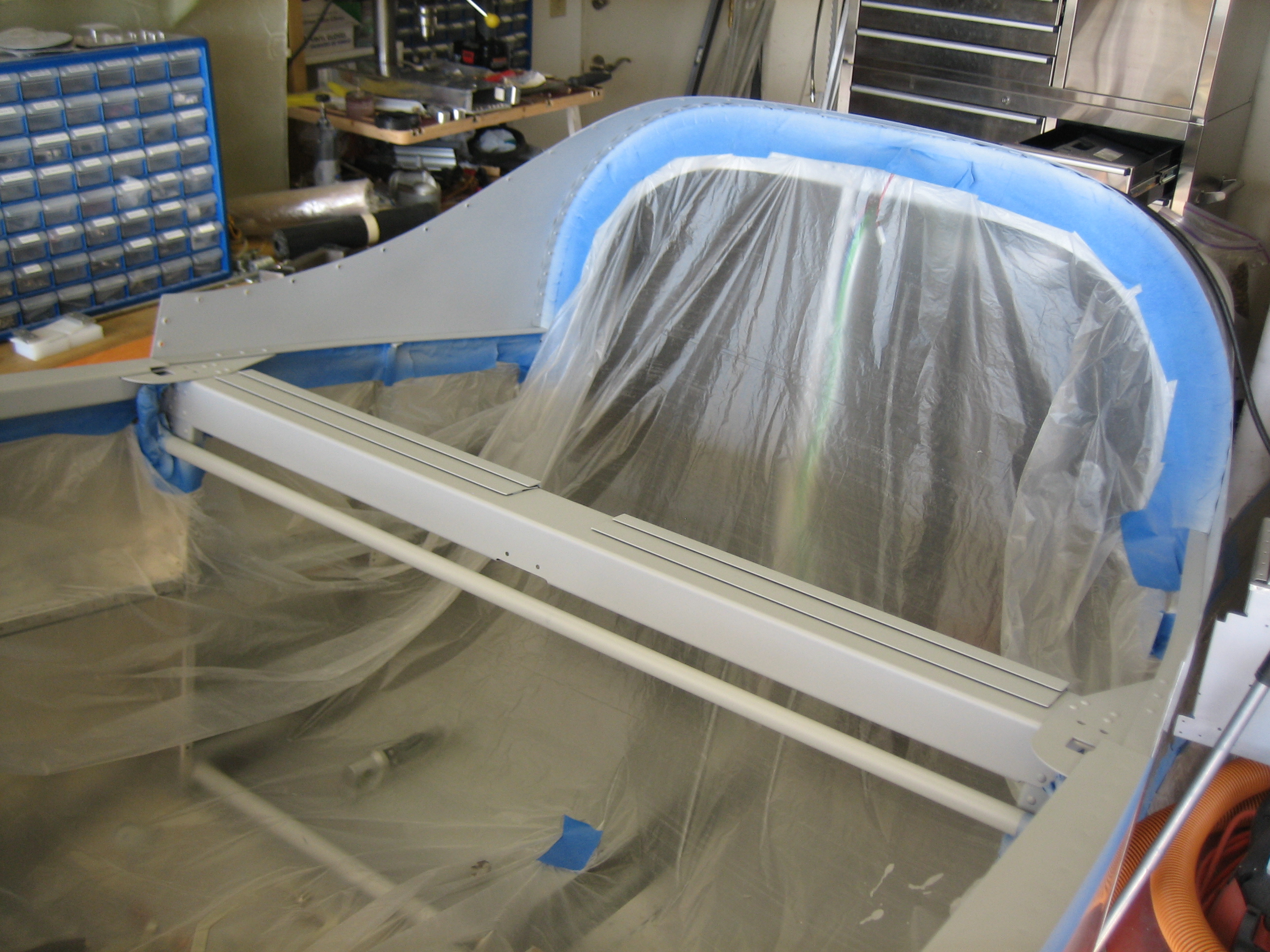
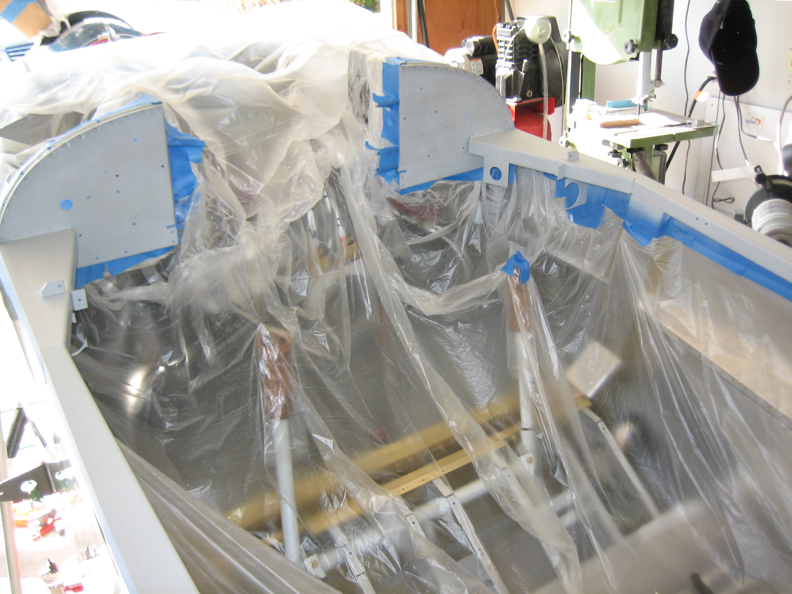
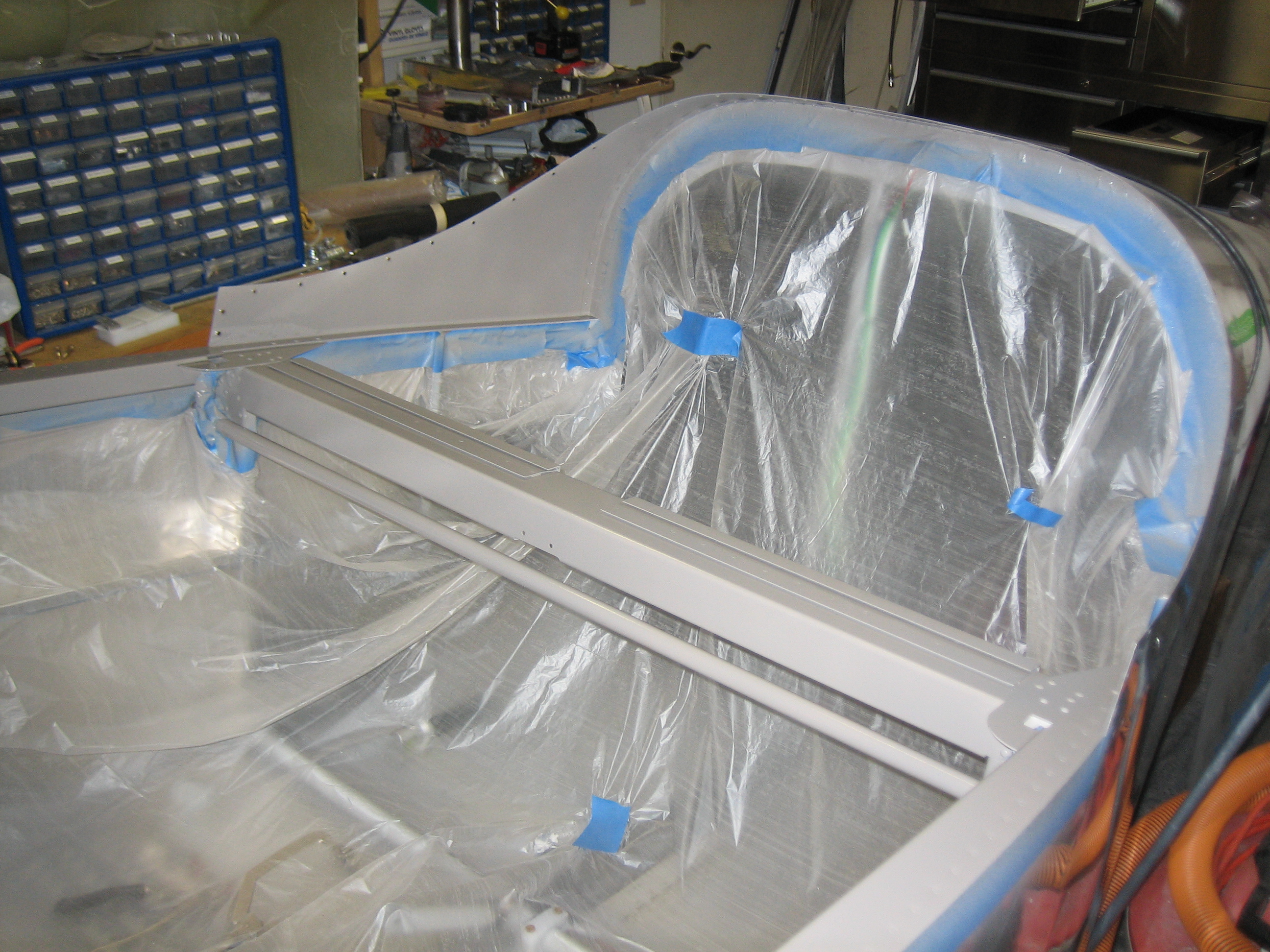
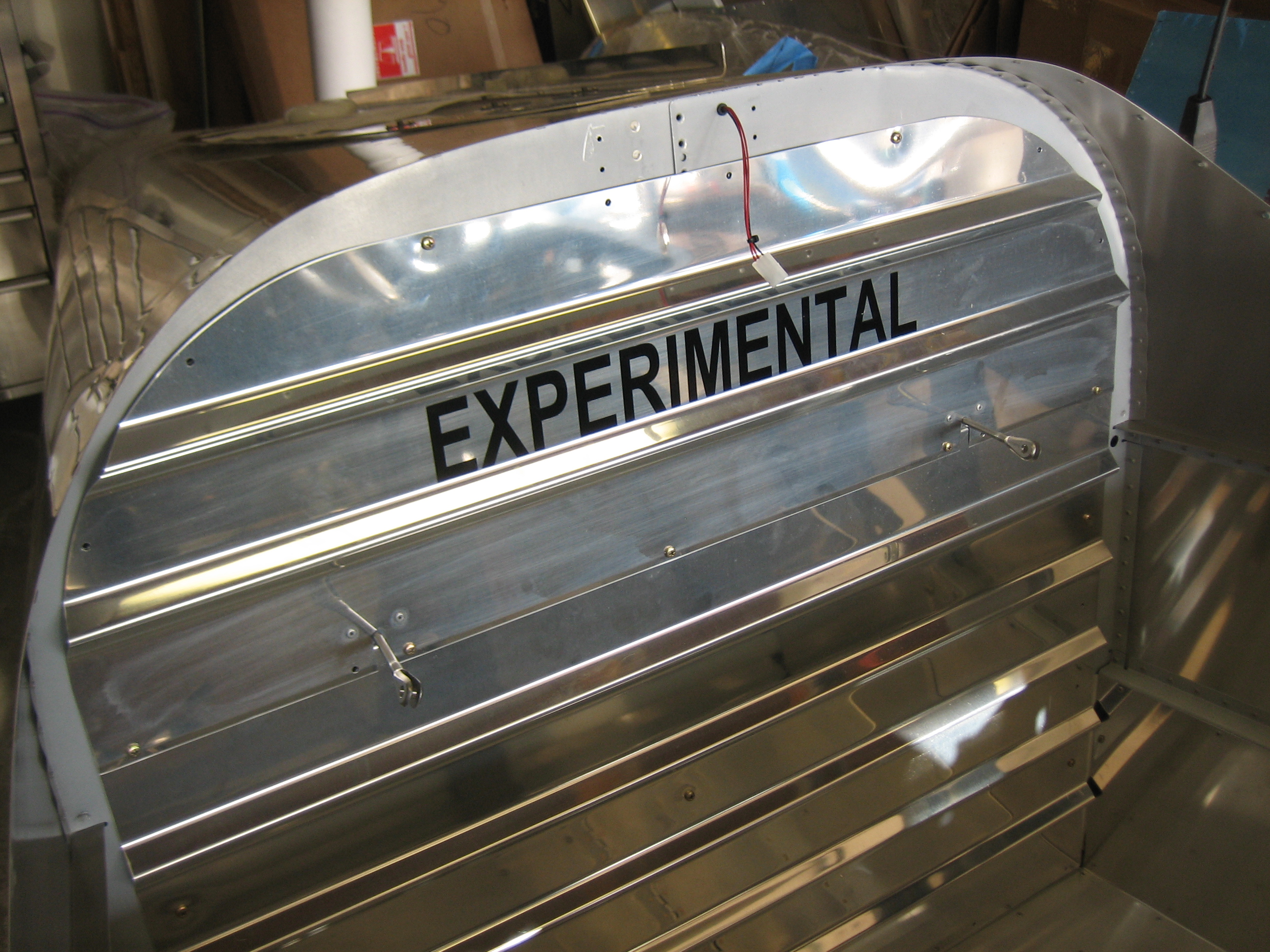
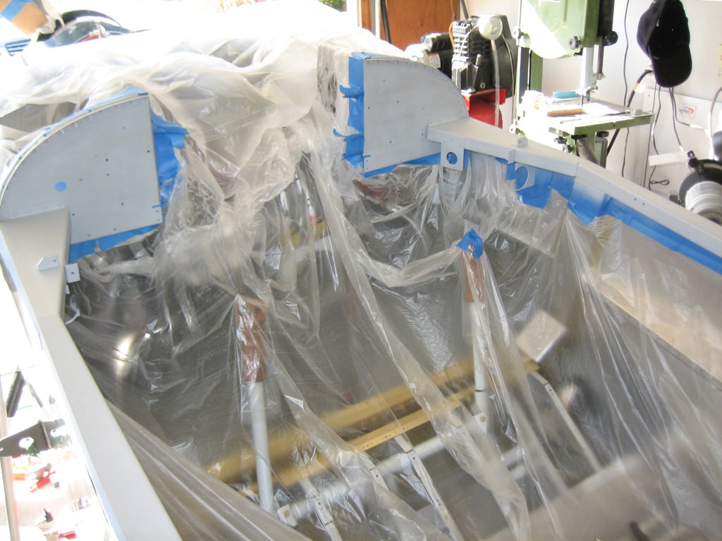
I masked off the interior and primed everything that will be painted.  I’m only painting the parts that won’t be covered by the Classic Aero Designs interior.

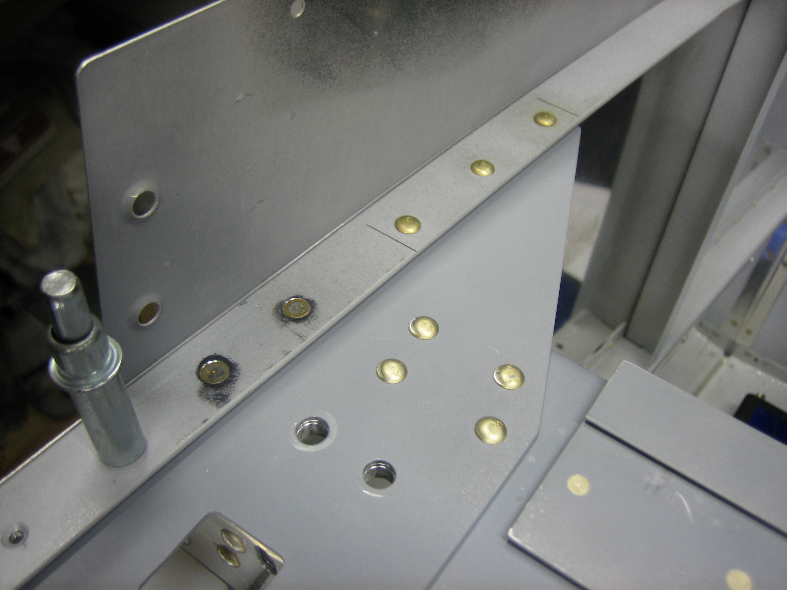
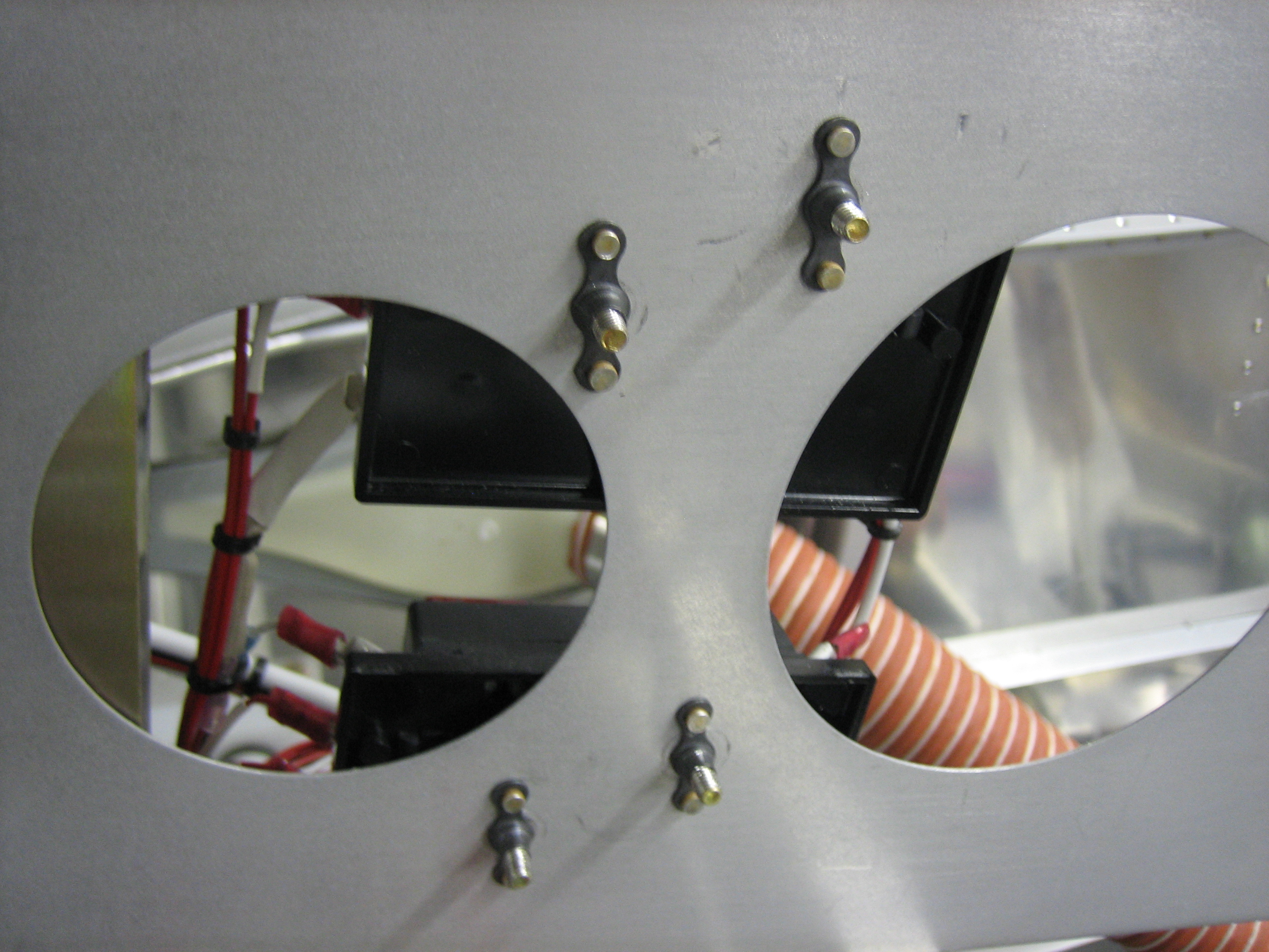
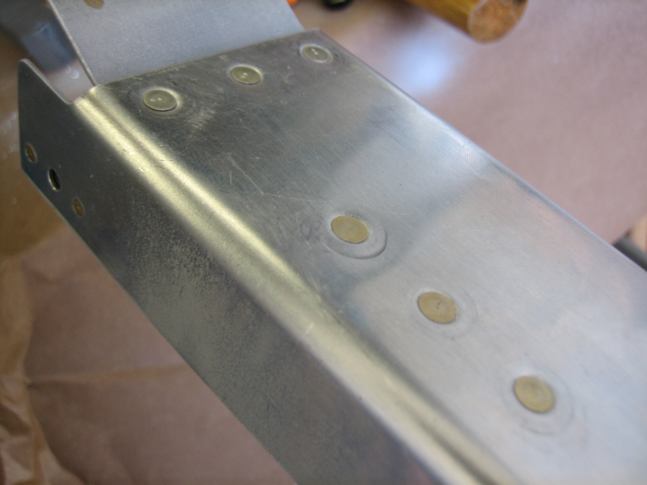
The canopy decks were primed up to the subpanel.

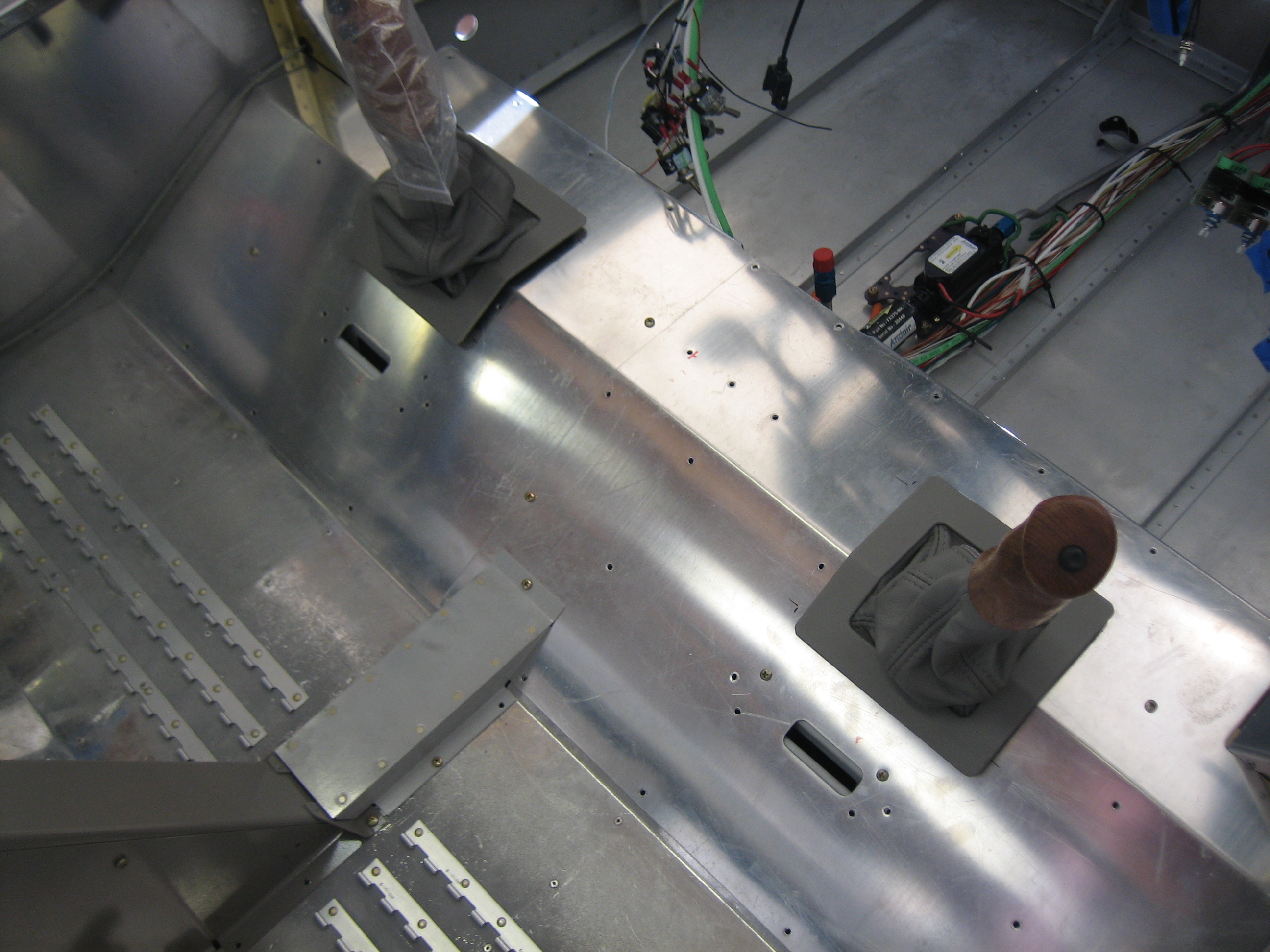
After that dried for a few hours, I painted everything with some paint that I had color matched to the leather used in the upholstery.

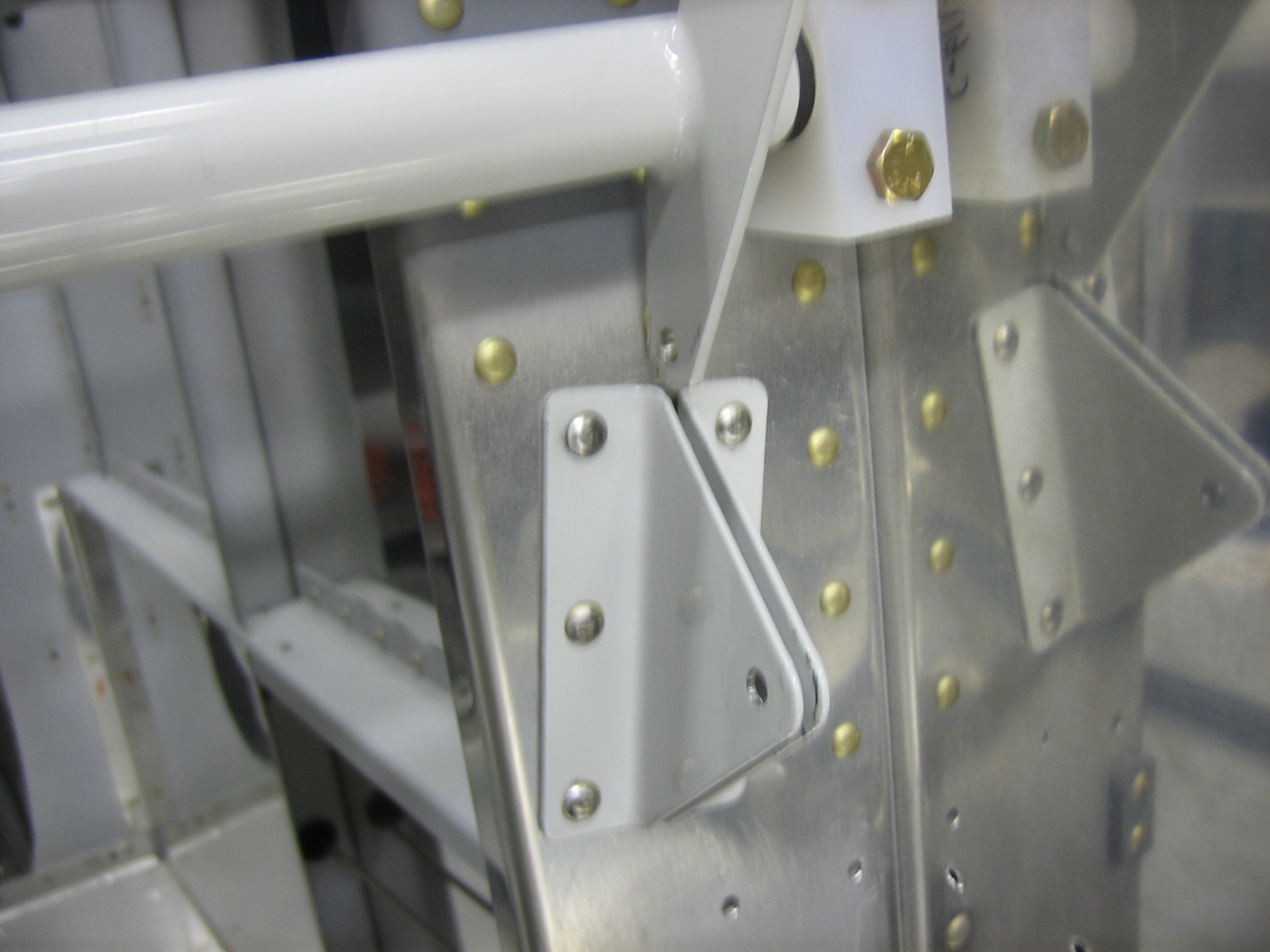
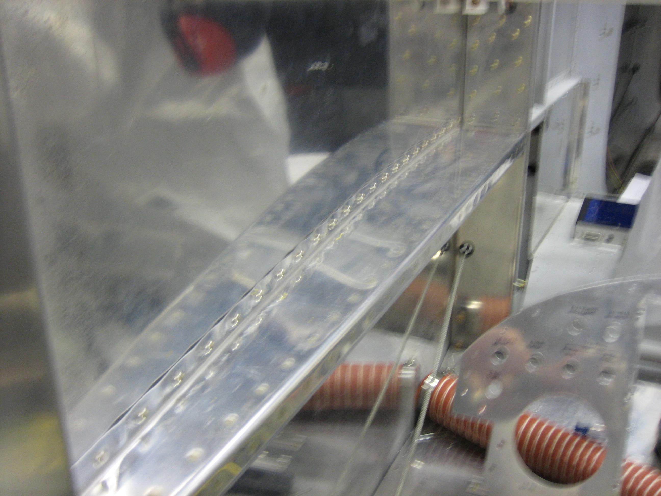
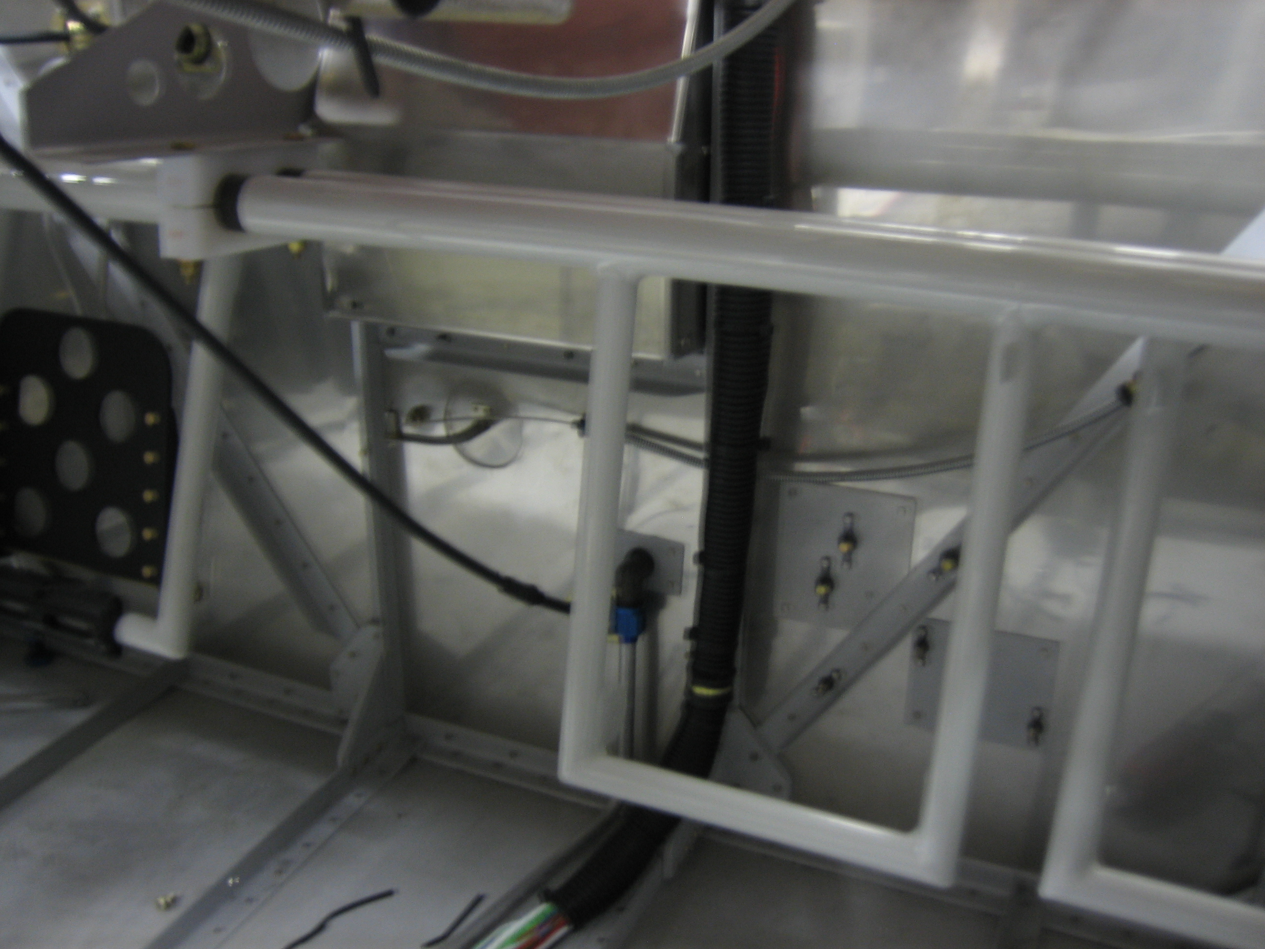
You can see here that I also painted the canopy latch torque tube since it’s visible between the seats and when the seat backs are pulled forward.

I put four coats of paint on (as specified by Stewart Systems).  This seems like a lot, but the first coat is a translucent tack coat with two more fairly light coats before the final heavier coat.  This greatly reduces runs since the early coats are very sticky.

Reinstalled Subpanel and Radio Stack

I reinstalled the center subpanel and Jenn helped me quickly knock out the rivets that tie it to the outer subpanel sections and forward ribs.  I then installed the canopy pivot blocks and radio stack.  You can also see that I added some blue tape on the canopy decks to protect the paint.

Miscellaneous Interior Stuff

After thoroughly vacuuming under the aft seat pans, I installed the forward seat pans and threw a few screws in to keep them in place.  I figured now was as good a time as any to fit the stick boots so that I could install the velcro around the stick opening.

I only have a little work left to do in the tail, so I put the lower baggage wall in place to that I could fit the interior.

Part of the flange needed to be trimmed to clear the wiring and tubing that I installed near the front edge of this rib for some reason.  There was no good reason I couldn’t have installed this near the back of the rib.

I then put the experimental sticker on the upper baggage wall and installed it.  I’ll generally have the upholstery cover over this, but I installed it anyway since I’ll likely fly without most of the interior during testing.

Worked on Heater Box and Forward Cover

I clamped some scrap angle with a radius on it to the heater box cover so that I could bend out all of the vents.

This will direct hot air from the engine down into the left and right footwells.

I also needed a notch on the right side to clear the heater box control cable where it passes through one of the firewall stiffeners.

I also cut a notch in the forward cover for the throttle cable.  I’ll clean this up and install a grommet to protect the cable.

Cabin Wiring, Paint and Air Vents

I installed some split conduit over the wiring bundle where it runs down the firewall.  This will keep it tidier and make it look better.

I also cleaned and primed all of the components to install forward of the spar to cover the center tunnel.

Finally, I formed some stainless steel mesh over the air inlet.

This will be installed here and the SCAT duct will hold it in place.  This will keep bugs and debris from getting pulled in through the air vents.

I then installed the SCAT tubing to the NACA duct…

…and to the air vent on the other end.