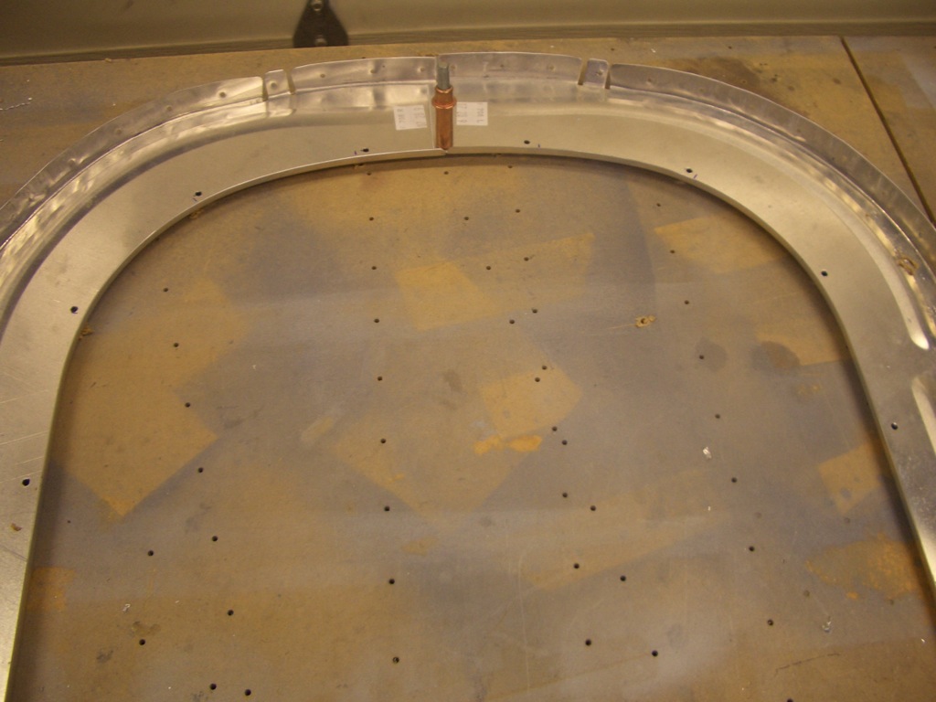
Attached Control Sticks

I fabricated the control stick bushings and mounted the control sticks tonight.  I’m still not happy with these though.  The pilot’s side stick has a little bit of play between the stick and the bushing, and the passenger side is binding a little bit.  It’s late though, so I’ll work on these more tomorrow.

Drilled Control Mounts

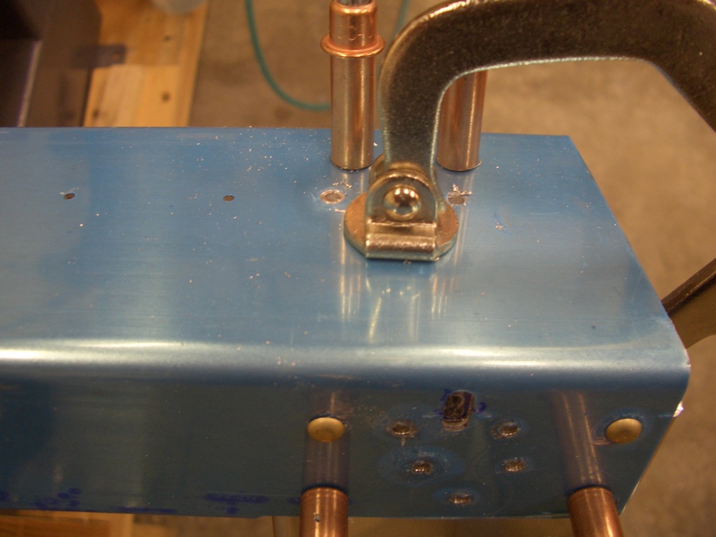
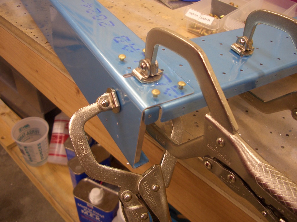
I drilled the control mounts to the aft center section.  This basically entailed laying out and drilling the top hole then bolting the mount in place and squaring it to the spar.  After clamping it in firmly in place, the other hole can be back drilled through the spar.

Center Section

I started out tonight by finishing the work on the controls.  After a little fiddling with both sides, I got everything working nicely with virtually no play.  I disassembled everything so that I can get the control mounts prepped and primed.

The plans say you can optionally remove the outlined material from the control mounts to save weight.  I’m trying to save weight where I can, so I’m doing most if not all of these optional steps.  I started by drilling some #30 holes to define the radius of the interior angles.

I cut out the bulk of the material using the band saw.  After this picture was taken, I smoothed out the cuts with a vixen file and the scotchbrite wheel so that these are ready for priming.

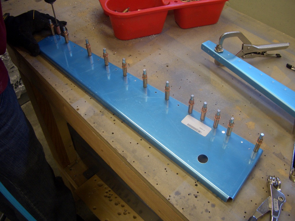
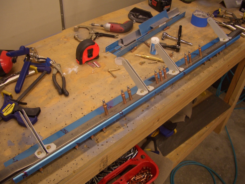
The center section has 18 K1000-08 nutplates that need to be installed on the top flanges.

I also deburred the edges of the center cover supports and match drilled these to the spar.  Nutplates are installed on the front flange and holes are drilled through the webs for snap bushings, but these can wait until tomorrow.


Finished Cover Support Ribs

I fabricated the web stiffeners that go on the other side of the shorter cover support ribs.  The plans don’t include the 45º cuts on the opposing flange, but I misdrilled the end holes, so I cut the flanges to remove the holes.

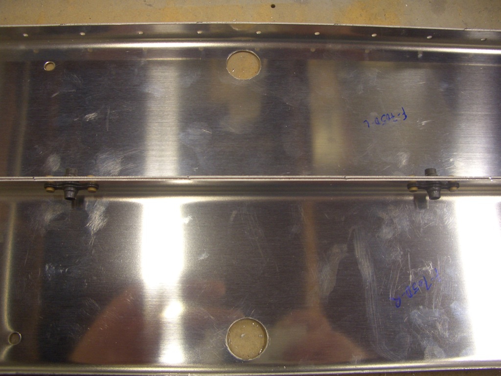
I primed the cover support ribs and installed the nutplates and snap bushings.

I also primed and installed the snap bushings on the web stiffeners.

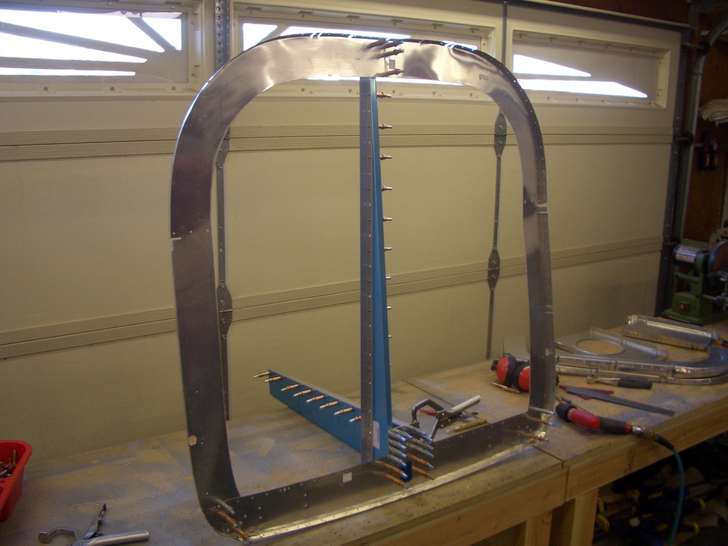
Here is everything installed.  The web stiffeners are riveted on the other side of the spar web under the two short cover ribs.  The short cover support ribs are screwed to the nutplates installed on the web stiffeners.  The longer cover support ribs are bolted through the spar bars at the top and bottom of the rib and riveted to the spar web through the middle.  If you look closely, you can see that the lower rivet in these ribs is missing.  I’m going to have to use my double offset rivet set to reach these and I’d rather wait until I have a riveting partner to use that.

Rear Spar Bulkhead

My buddy Andre stopped by today to give me a hand with the rear spar carry-through bulkhead.  First up is to shoot the two rivets I couldn’t do easily yesterday.  I didn’t get a picture of it yesterday, but I also riveted on the main spar uprights.  A few of these rivets could be squeezed, but most needed to be shot and bucked.  I’m definitely getting the hang of doing that solo.
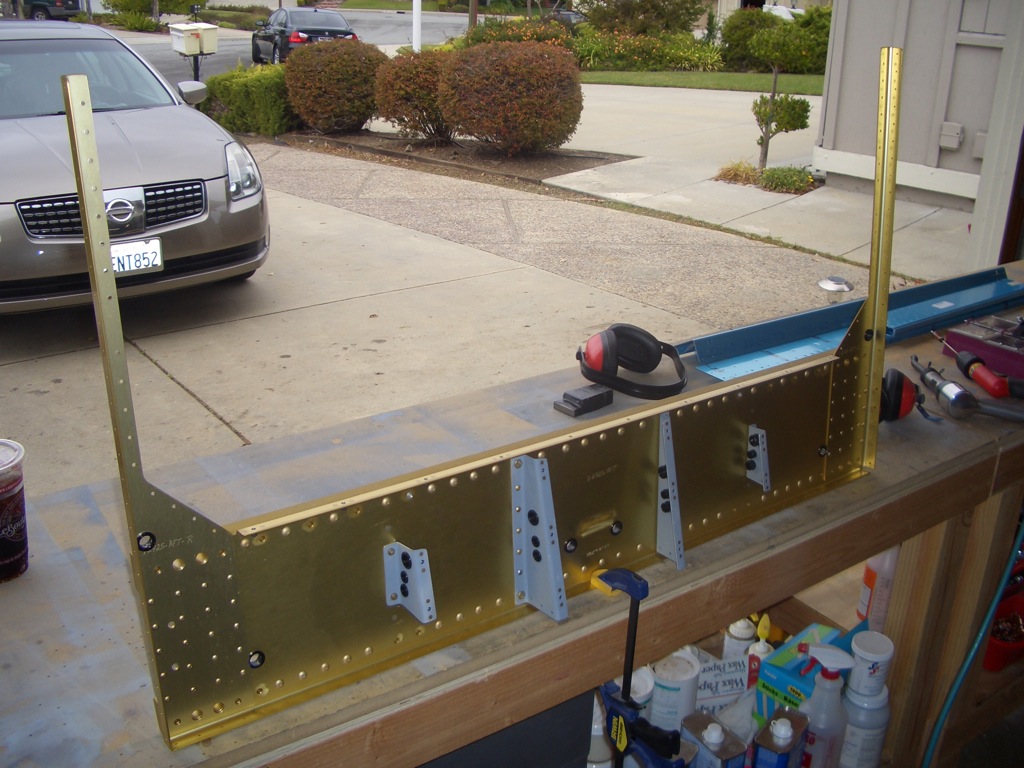
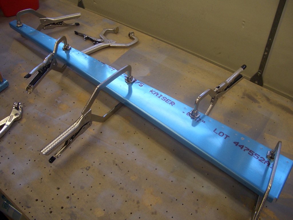
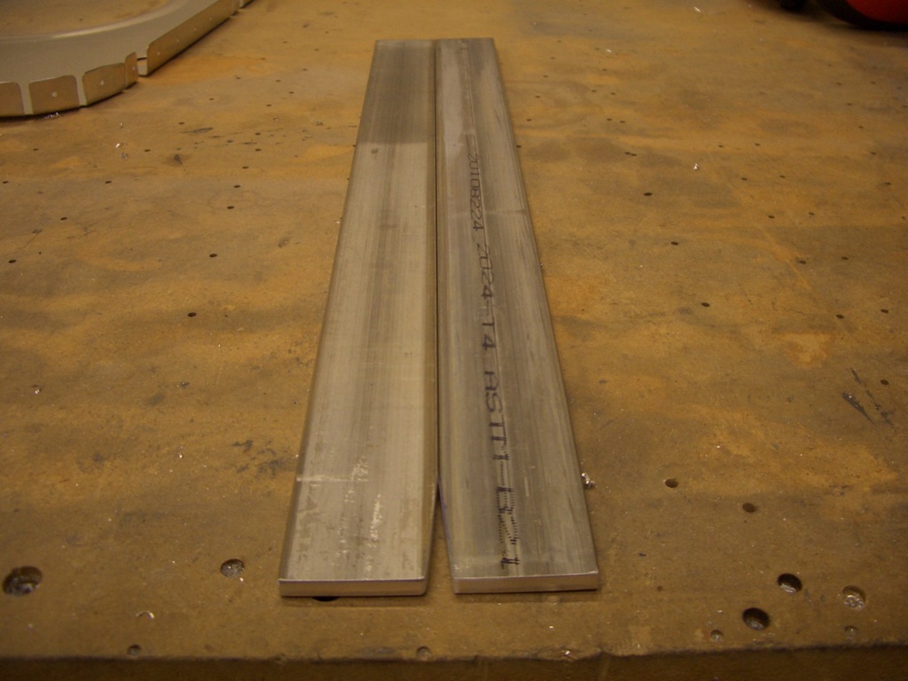
The rear spar bulkhead starts with a could of beefy pieces of 2024-T4 bar stock.  The lower one in this picture runs all the way across the bulkhead and carries the major portion of the load.  Shorter pieces of bar stock with a couple of bends in them are riveted to these to create a socket which will receive the rear wing spar.
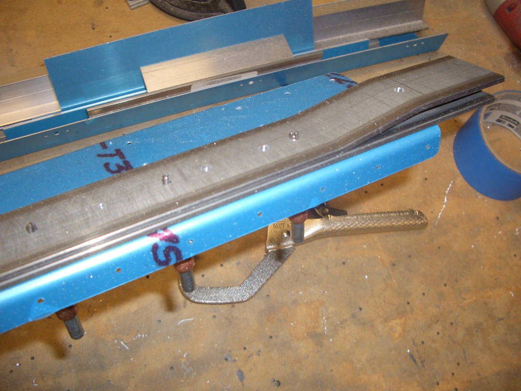
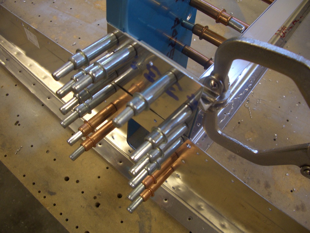
The lower seat belt attach points are drilled and bolted to the rear spar carry through structure.  The technique here is to mark and drill one side that then clamp the other side in place with a 3/16″ spacer.  An AN3 bolt is exactly 3/16″ thick, so clamping one of these between the anchors creates the perfect spacing.  The holes in the top of the anchors (off the top of the picture) are held in alignment with an AN4 bolt.  The other anchor can then be back drilled through the spar.  You can also see here the outboard seatbelt attach points require the anchors to be cut to clear adjacent rivets.  Here, the left anchor has been cut, but the right one is still full size.
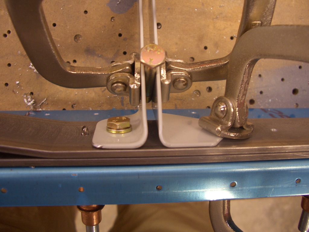
Here are all four seat belt attach points match drilled to the spar.
The shorter spar bars are tapered for weight reduction.  You need to make sure that the last rivet has 1/4″ edge distance all around the radius.  By positioning this end first, I could easily ensure that.
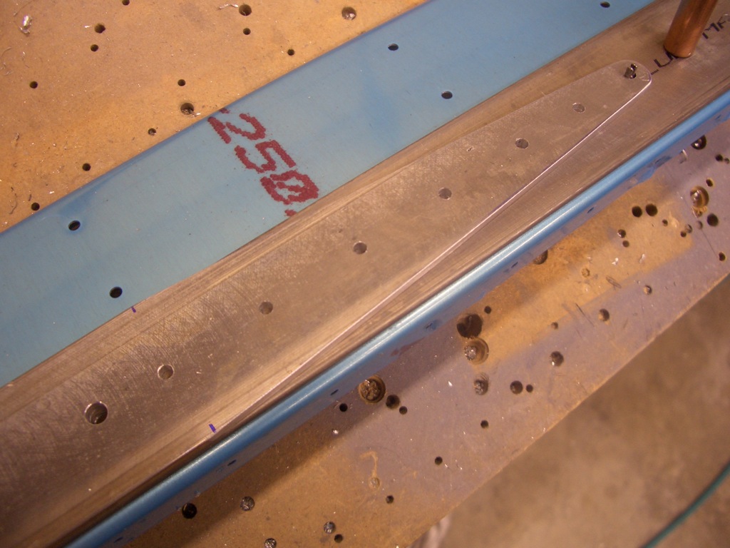
Then the other end can be cut flush with the long spar bar.
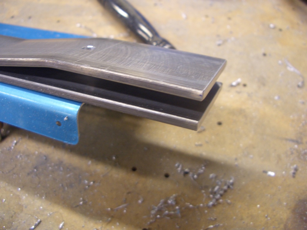
While I was working on the rear spar, Andre fabricated the upper angles that will receive the canopy latch pins.
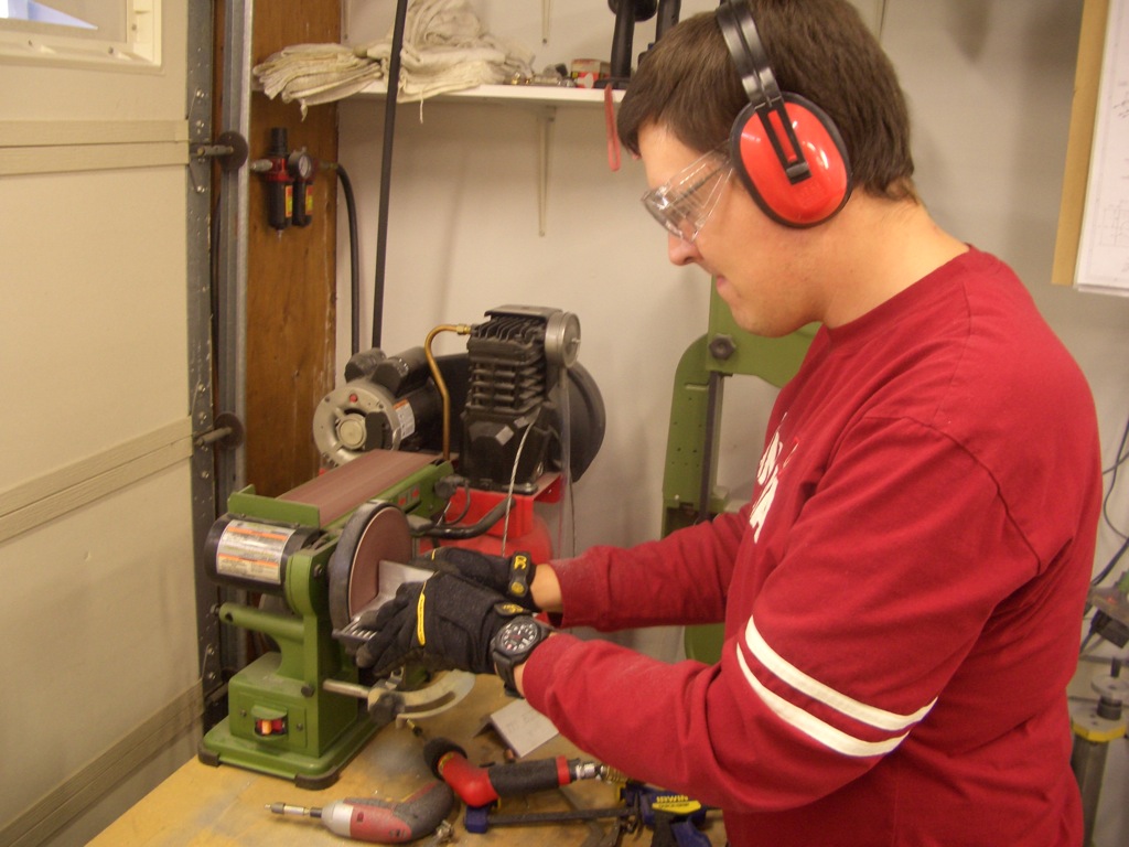
The angles fit behind the upper portion of this bulkhead.  I drilled the four corner holes so that I could use rivets to keep the three prepunched pieces in alignment.  The angle could then be clamped in position and the holes match drilled.  I’ve said it before, but these self-adjusting clamps absolutely rock.
Worked on Rear Spar Bulkhead

I cut all of the pieces that form the upper seat adjustment.  I started to layout the holes, but I realized that my rivet fan won’t adjust wide enough.  Instead of doing this old-school, I’ll borrow a large rivet fan from a friend.

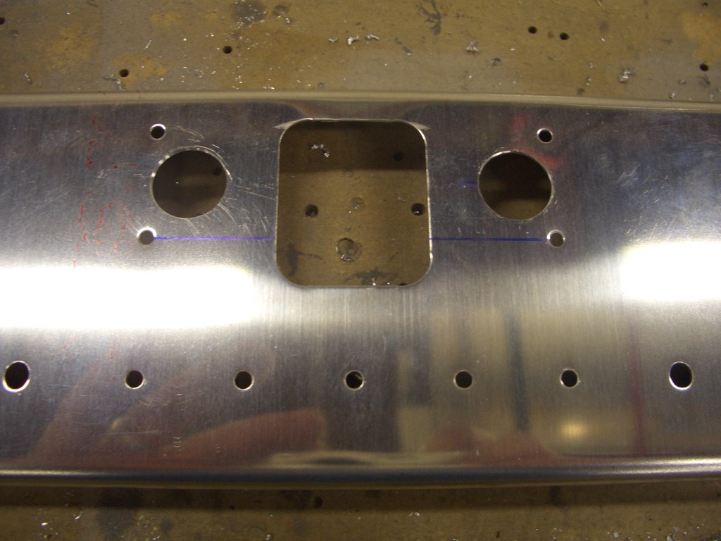
The lower bulkhead needs a couple of 5/8″ holes for snap bushings to run wires through this area.  Edge distance to the adjacent holes is right at the recommended amount.

The F-705D uprights need 5/8″ holes as well for the rudder cable snap bushings as well as a couple of K1000-08 nutplates each.  I installed these before priming because I’m only going to prime parts now that won’t get a top coat of the interior color.  I’ll also probably use self-etching primer for all of the cabin components so that I can easily wipe off the primer at some point in the future if I need to paint an area.

More Work on F-705 Bulkhead

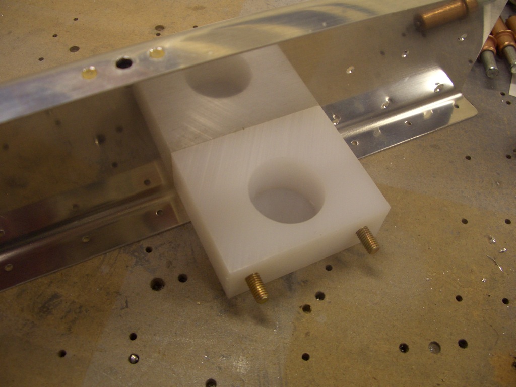
I drilled the flap blocks to the sides of the F-705 bulkhead.  These won’t be bolted on until much later in the construction, but it’s easiest to drill them now.

I also drilled the four holes in the top of the two F-705G angles.

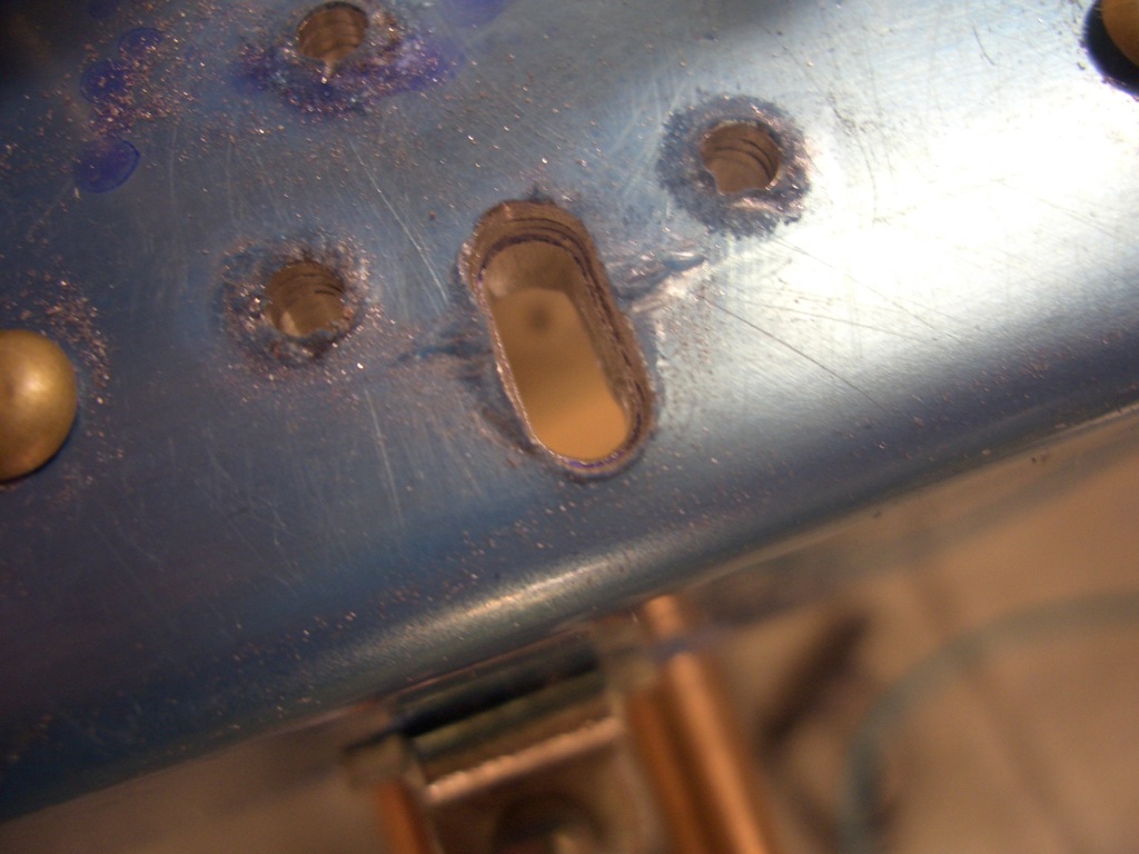
…as well as drilled and filed the elongated holes for the canopy latches.

I managed to get all of the holes in the F-705 bulkhead deburred.  I still need to finish the upper seat back adjustment parts, then this will be ready to prime and rivet together.

Finished Bulkhead Fabrication

I had the day off work, so my buddy Andre dropped by and we got started on the F-706 bulkhead.  First up is to drill some 0.063″ angle to a couple of support ribs.  Here is the rib that goes from the back of F-706 back to F-707.

And here is the rib that runs vertically behind F-706.

Here are how all of the pieces fit together.  The reason there is so much structure near the bottom of this bulkhead is that there is a bellcrank mounted here that connects the forward elevator pushrod (from the control sticks) to the rear elevator pushrod (to the elevator horns).  All of this is now match drilled.

Here is a closeup of this area.  The forward elevator pushrod passes through the hole visible here.  The bellcrank mounts between the two ribs near the top of the picture.

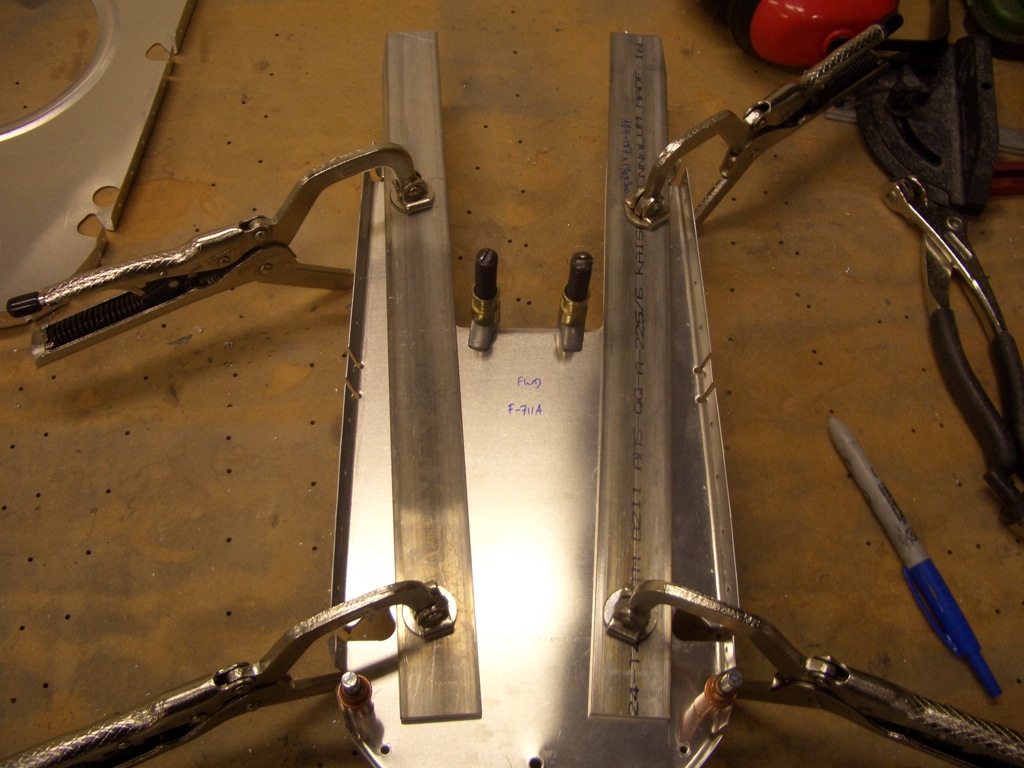
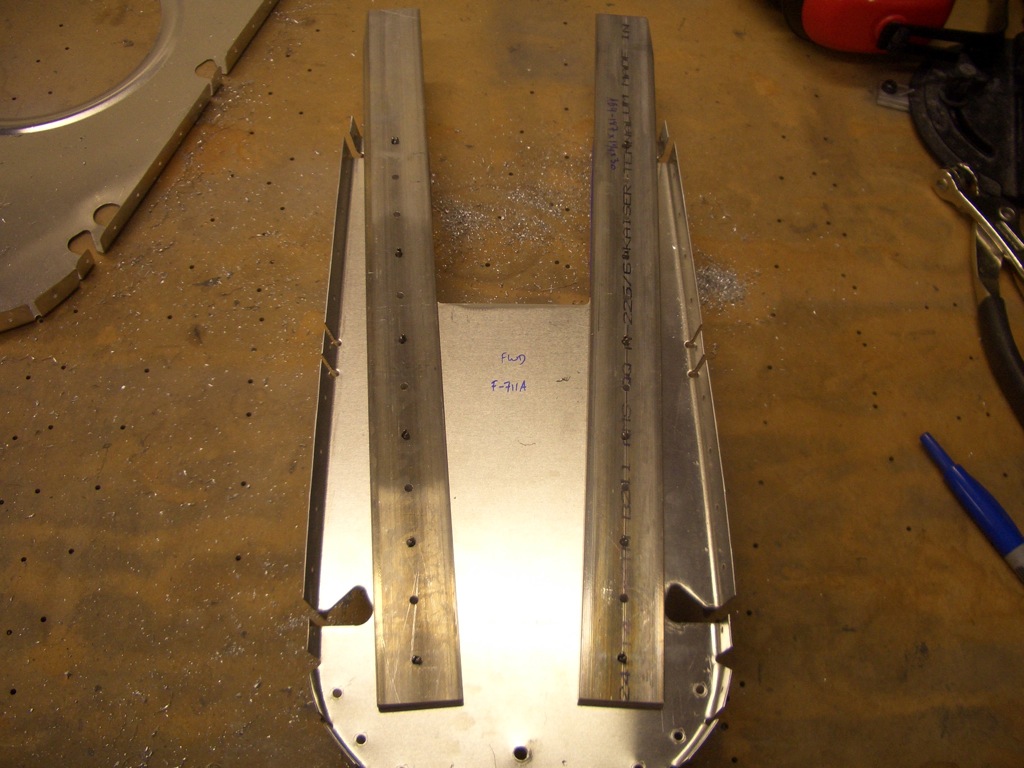
I also fabricated the straps that attach the horizontal stabilizer to the F-711 bulkhead.  Near the bottom you can see a taper cut into these to clear the side skin of the fuselage.

These are positioned against the front side of F-711 such that the bottom hole is 5/8″ up from the bottom edge and the top edge is 3 19/32″ from the top of the bulkhead.

These are then back-drilled through the bulkhead.

I drilled a series of eight holes along the inside edge of the F-708 bulkhead to attach the static tubing.  I also drilled holes in F-706 and F-707 (the two bulkheads forward of this one to pass the static tubing up to the front part of the fuselage.  There are also rudder cable holes in almost all of the bulkheads that require opening to 5/8″  With this, I think I am done with all of the drilling for the bulkheads (for now at least).  Everything can be disassembled, deburred, dimpled and primed in preparation for riveting.