Finished Cabin Frame Attach Angles

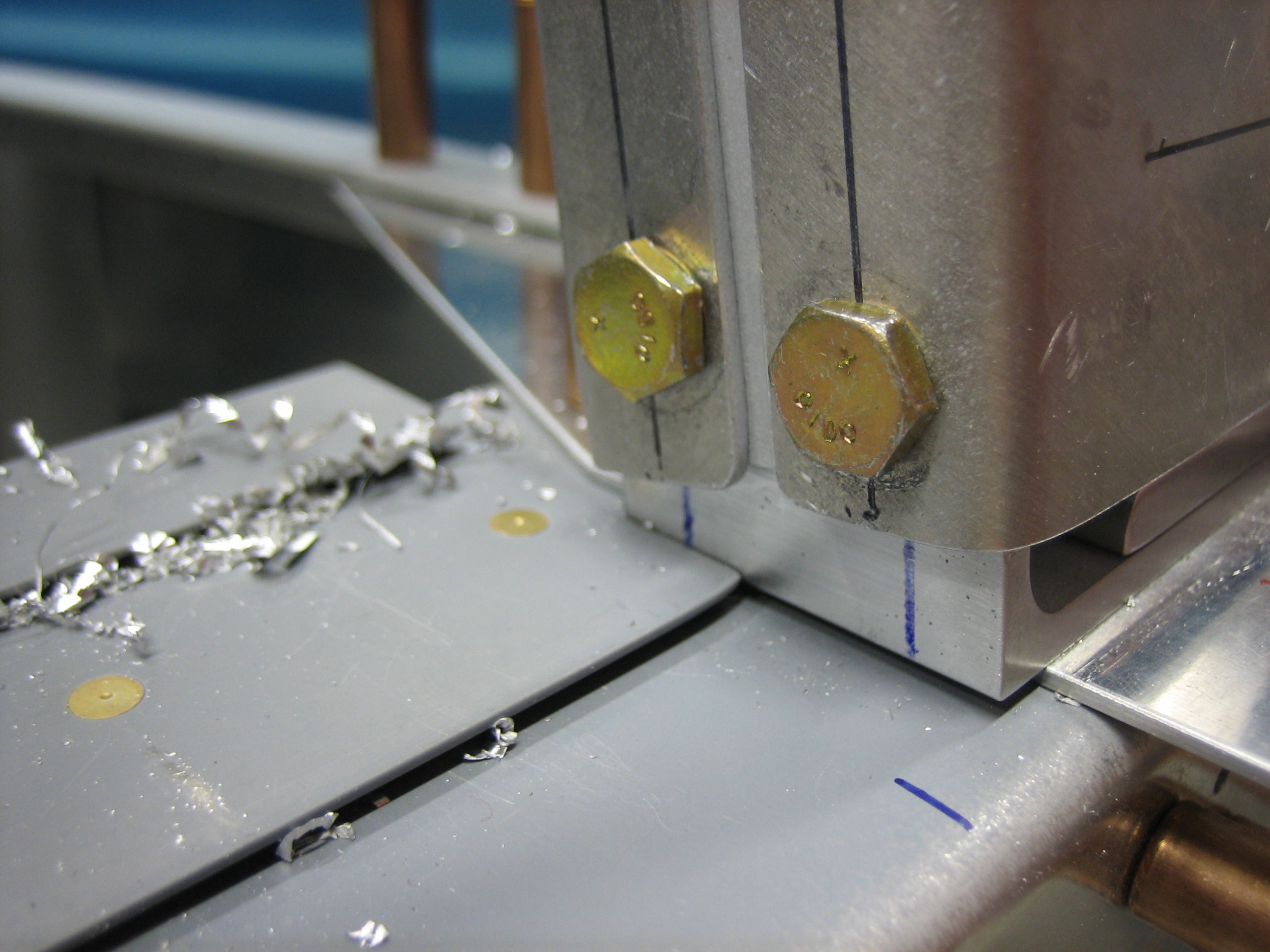
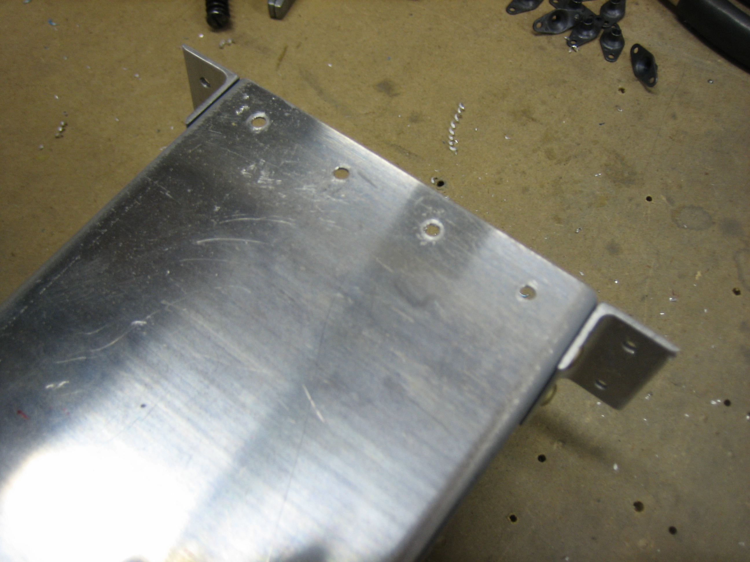
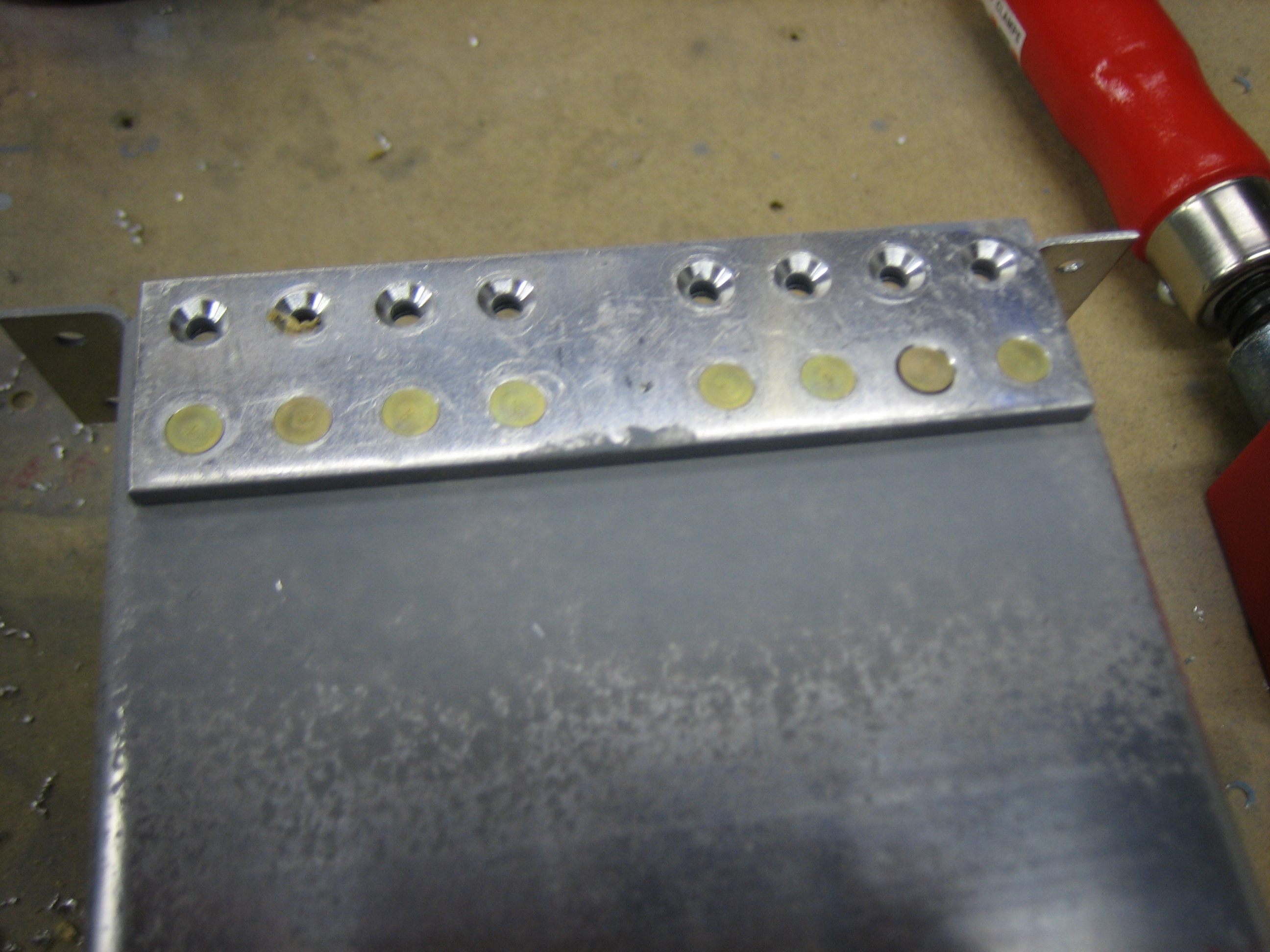
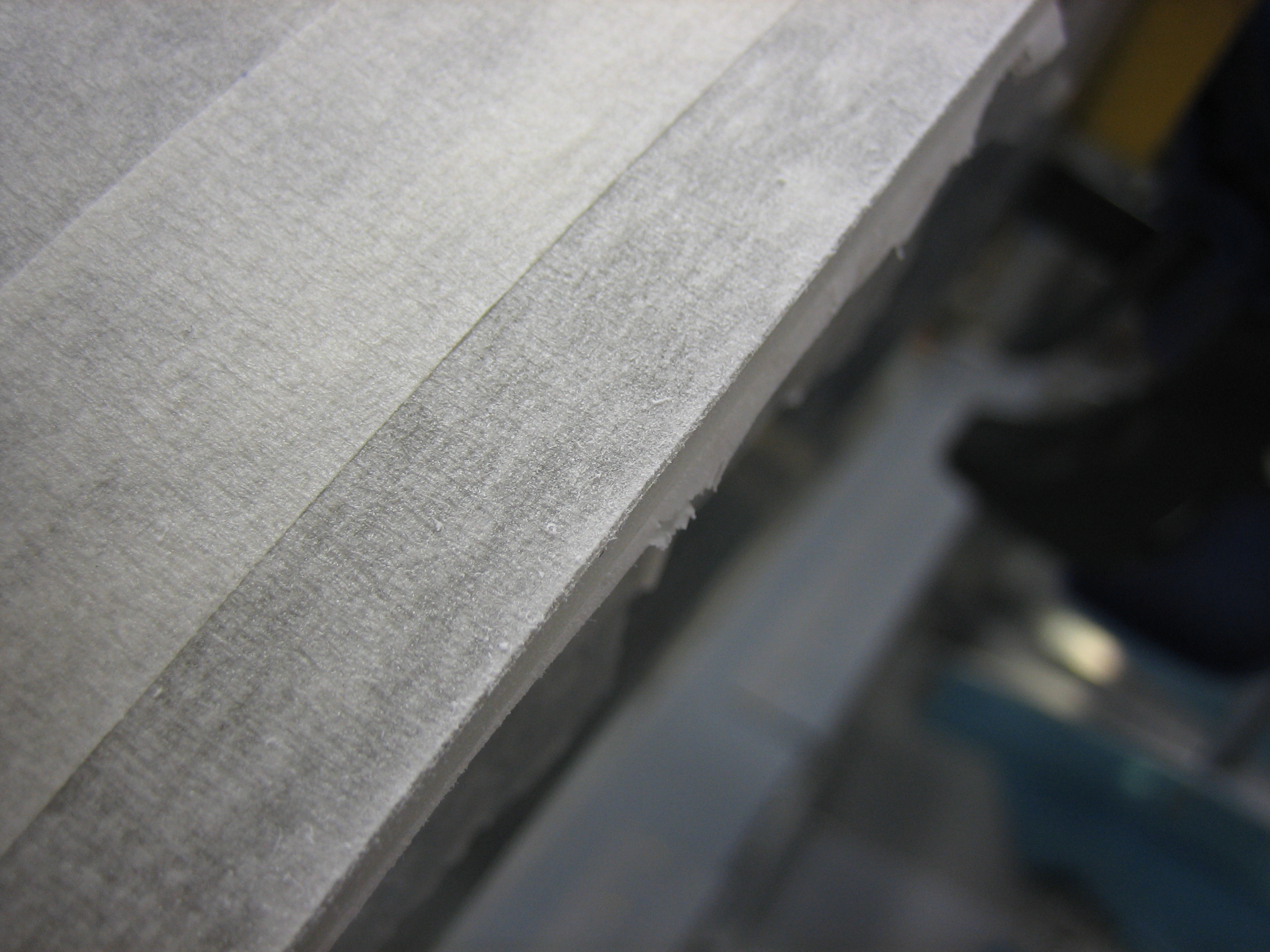
I finished trimming the cabin frame attach angles so that they’re flush with the sides of the fuselage.  I alternated between using the vixen file and the disc sander, then finished up with the scotchbrite wheel.

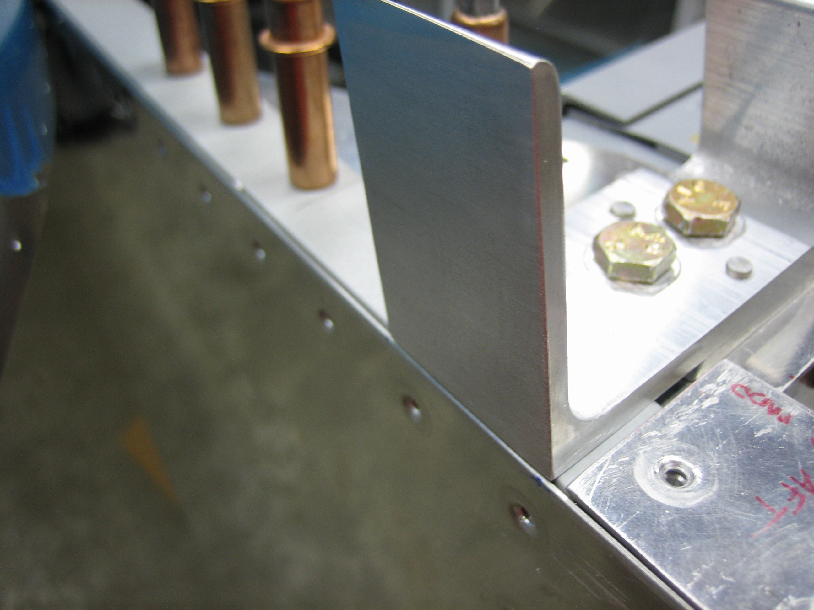
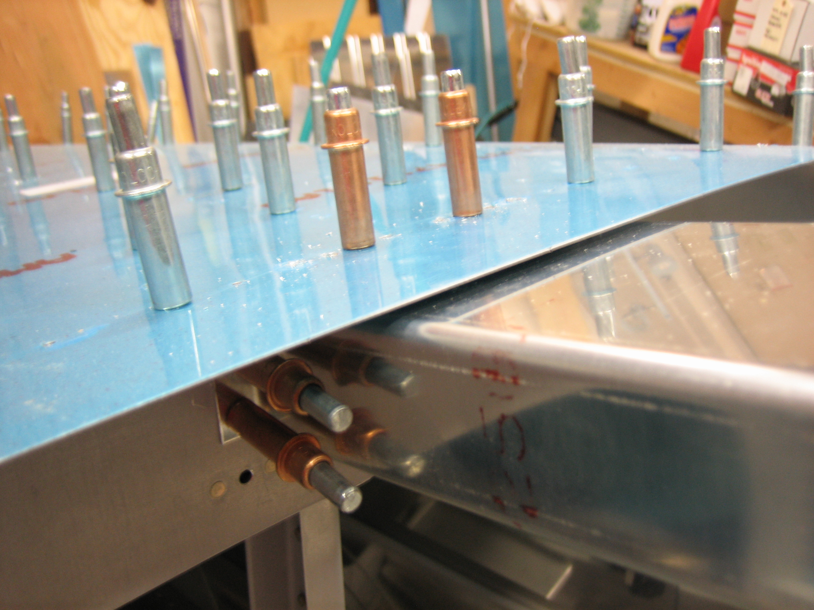
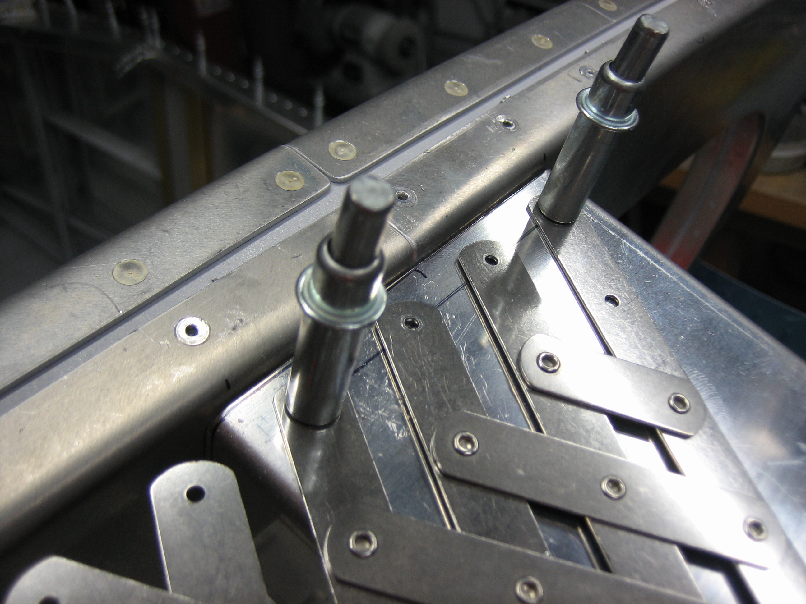
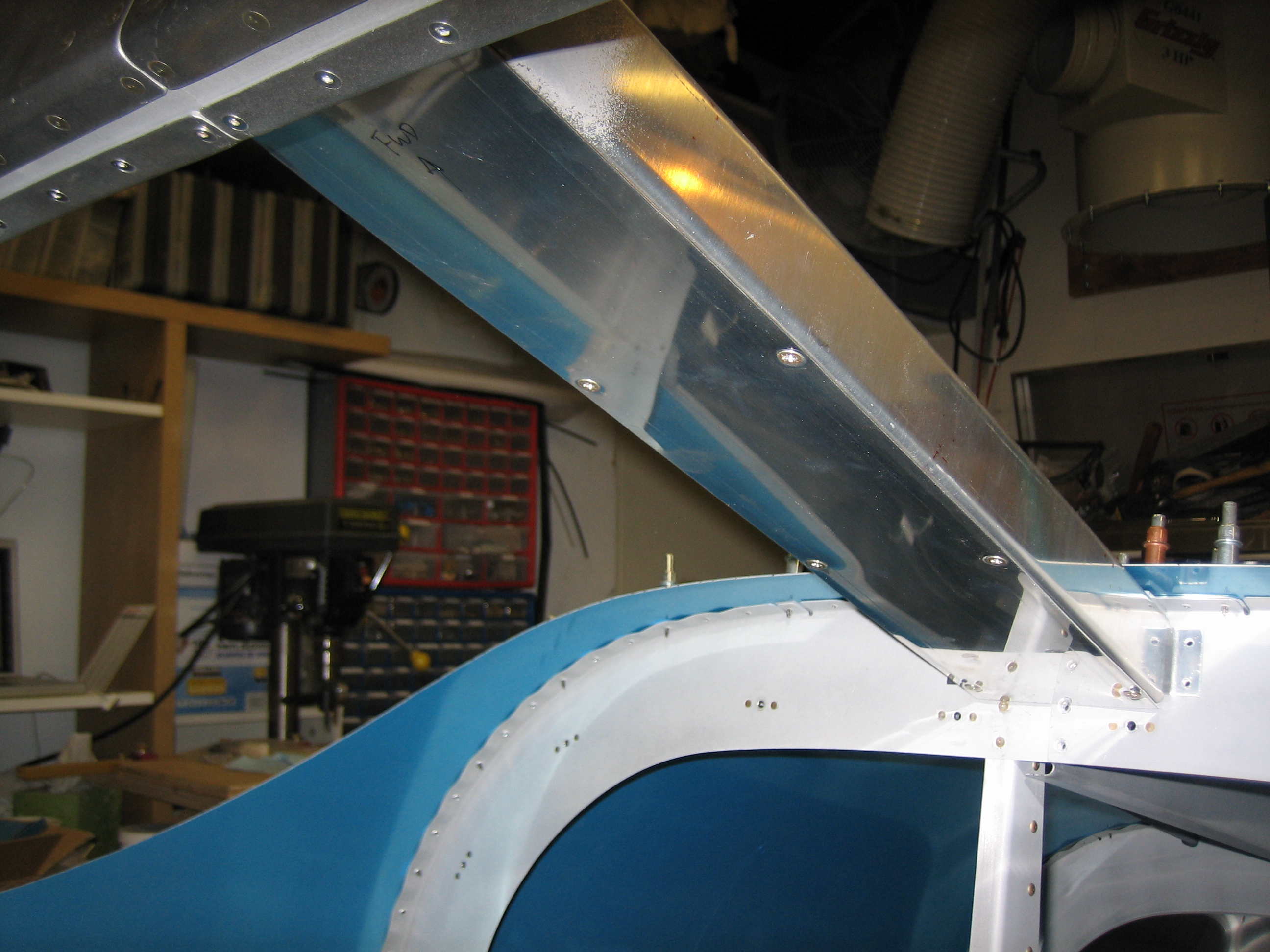
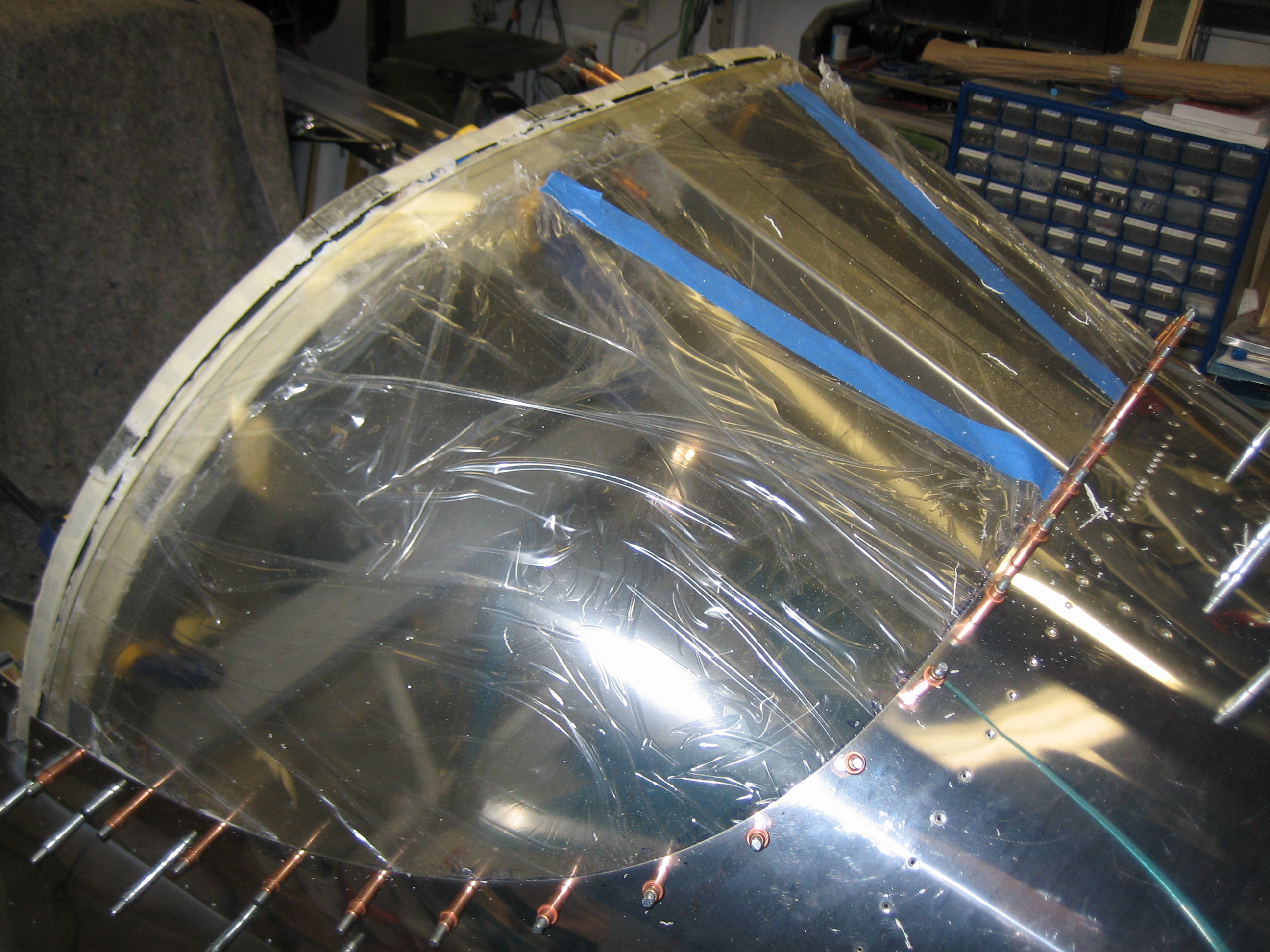
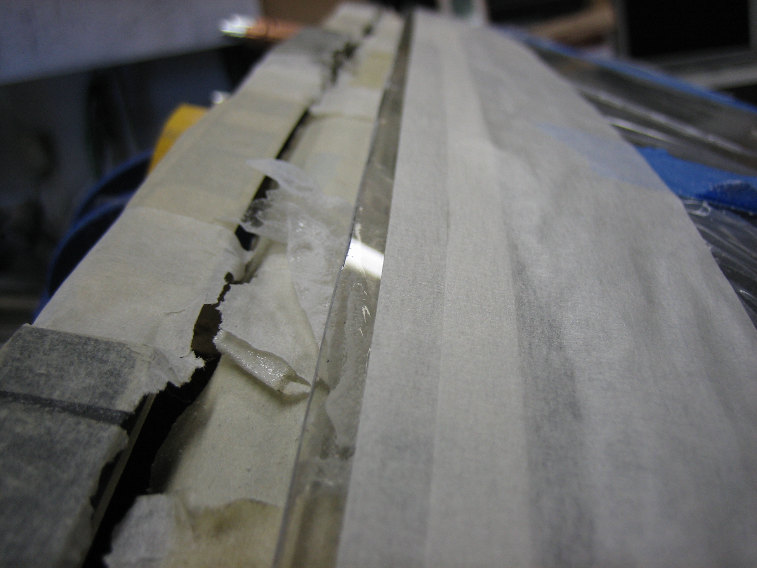
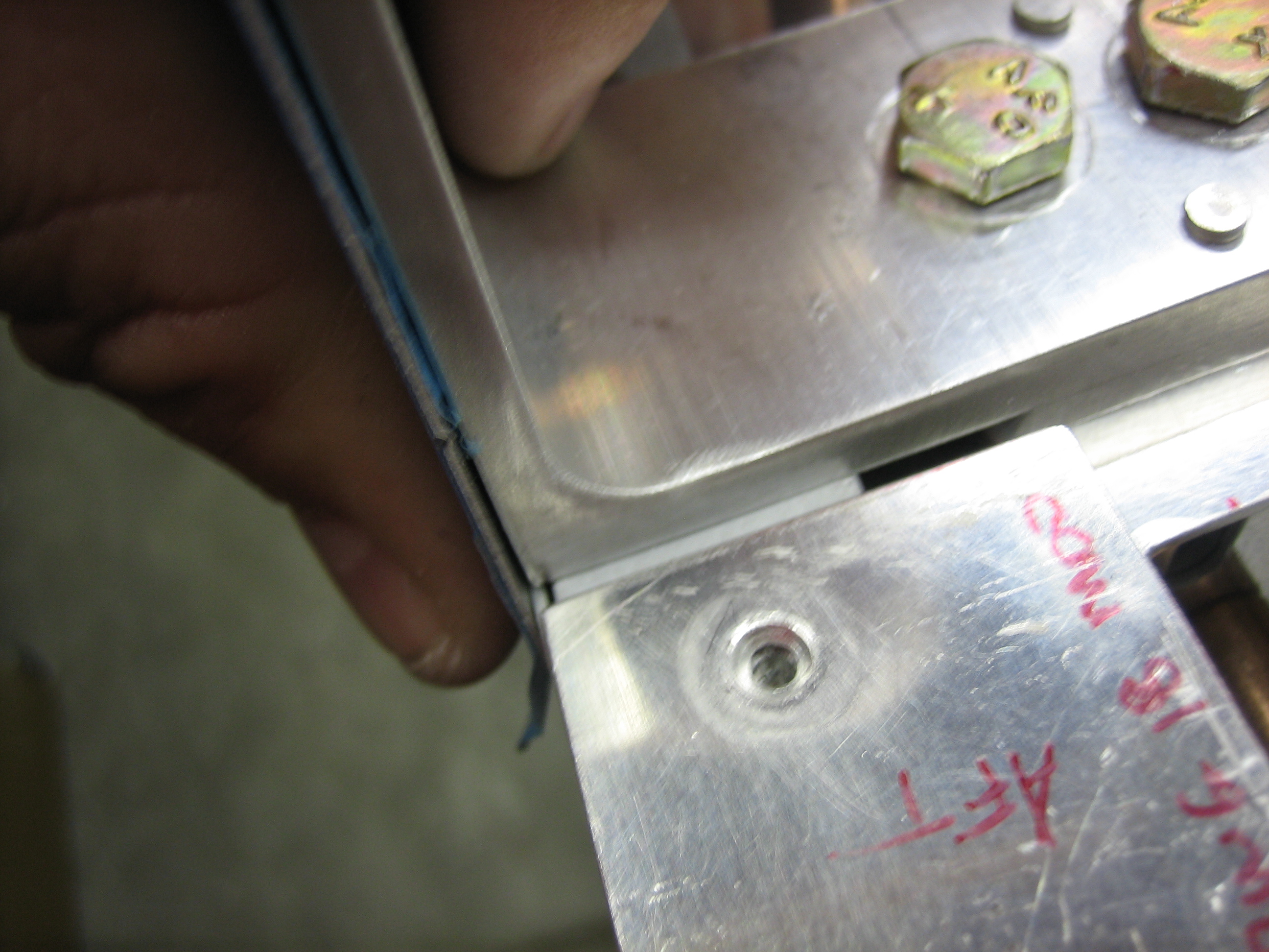
Here you can see how the aft top skin lays flush against the side of the angle.

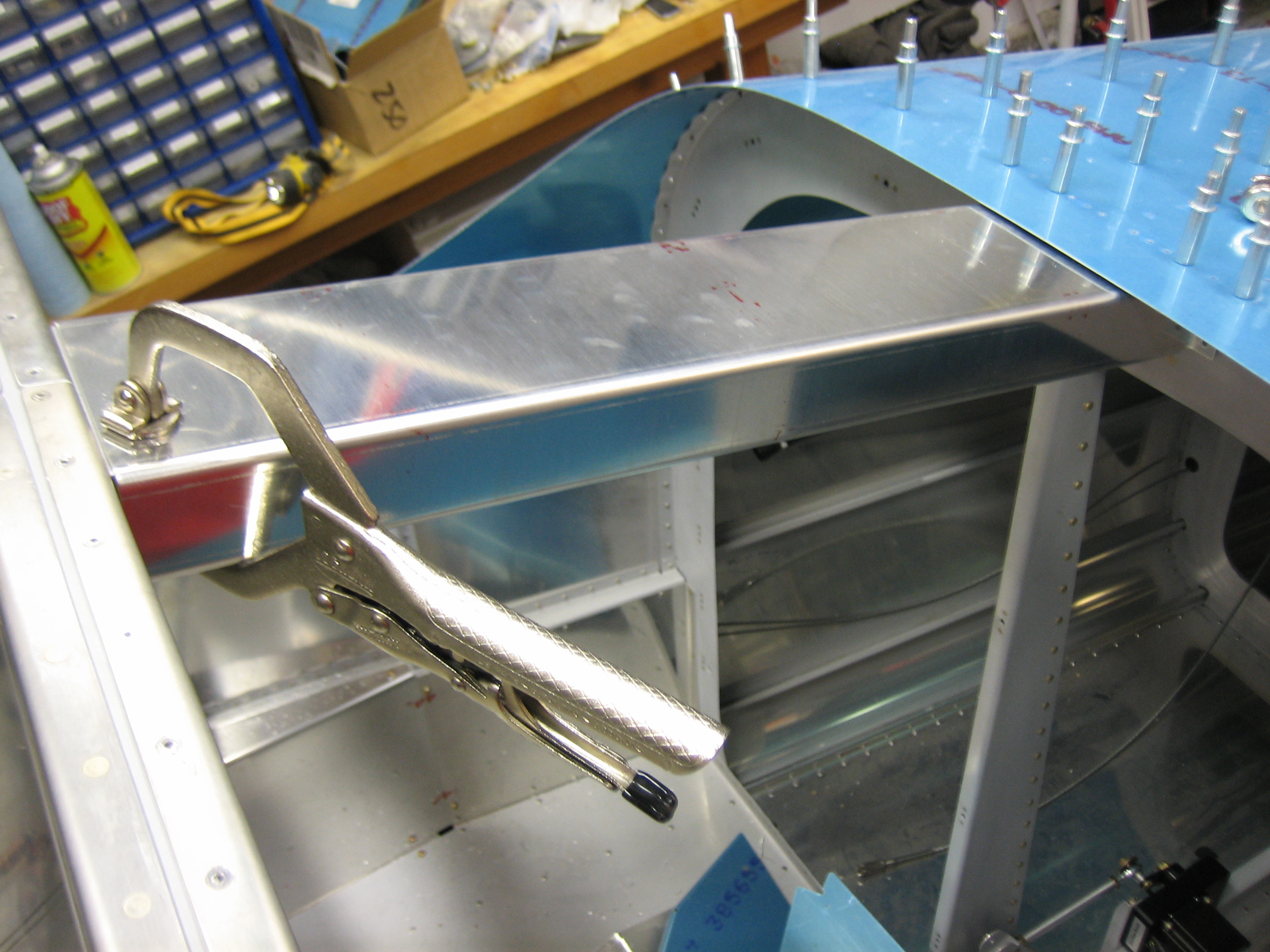
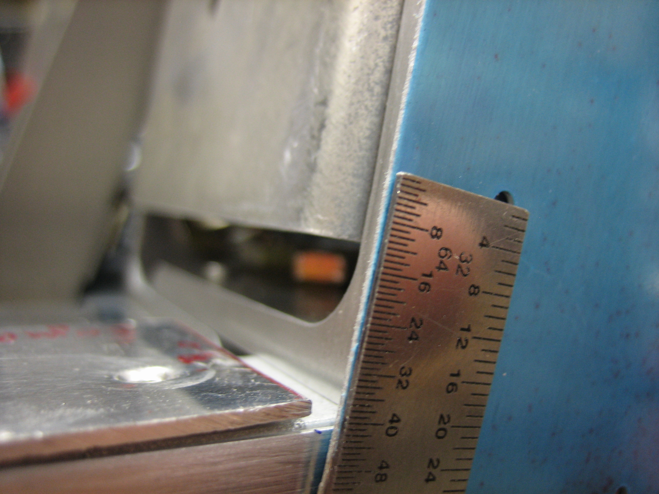
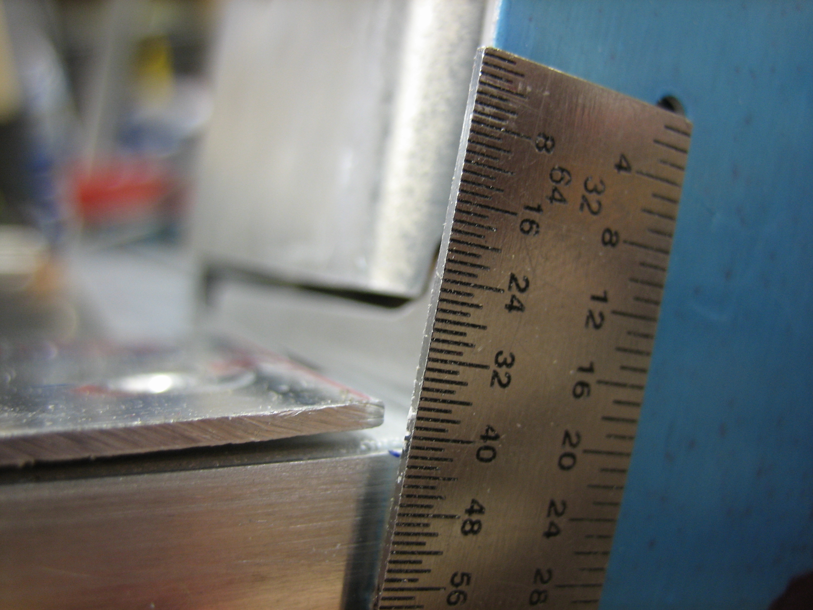
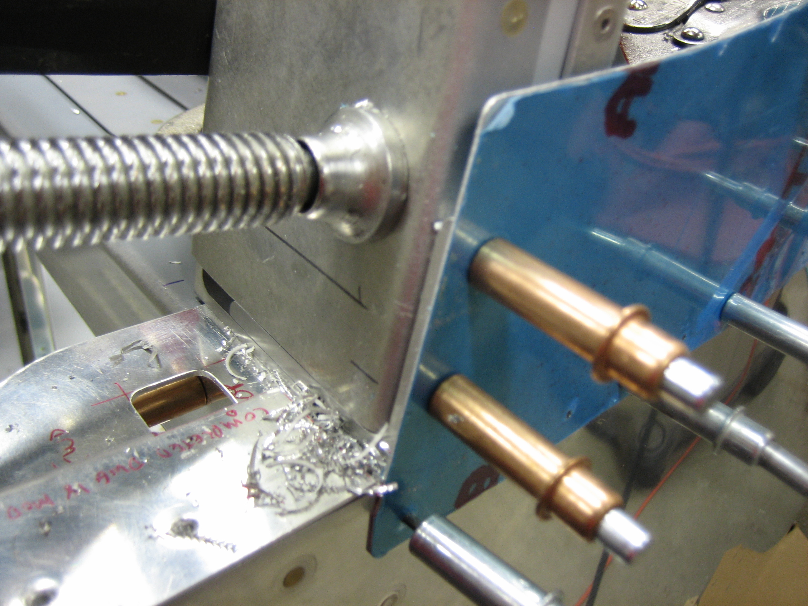
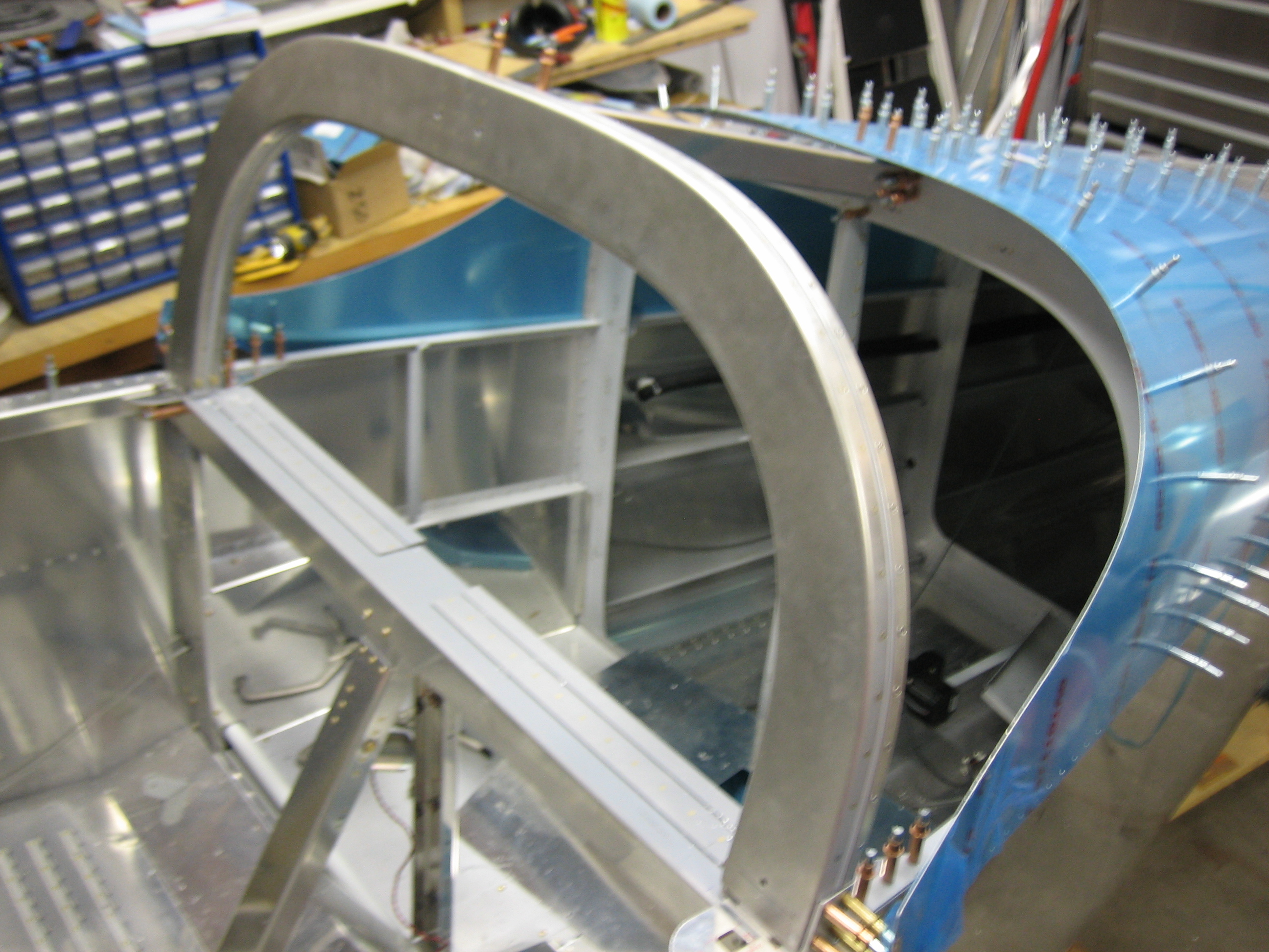
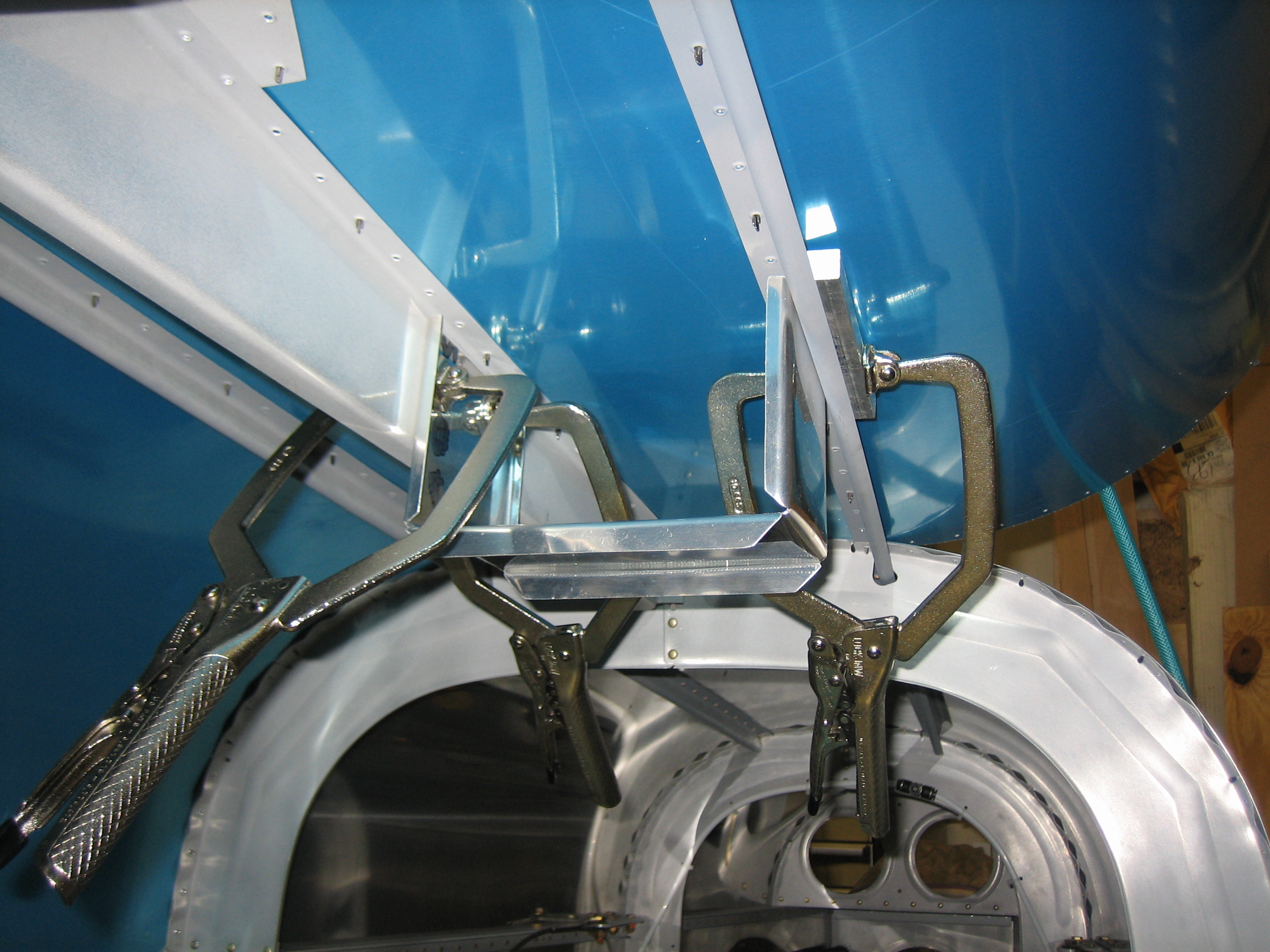
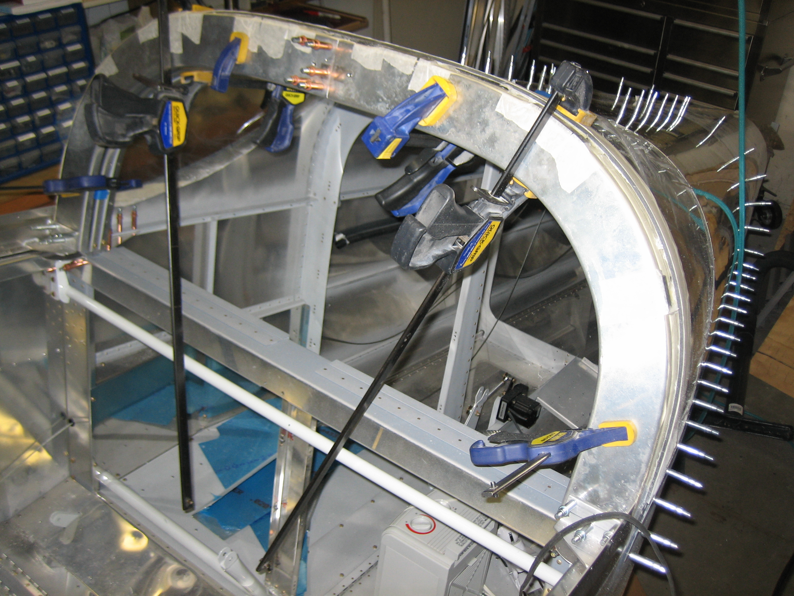
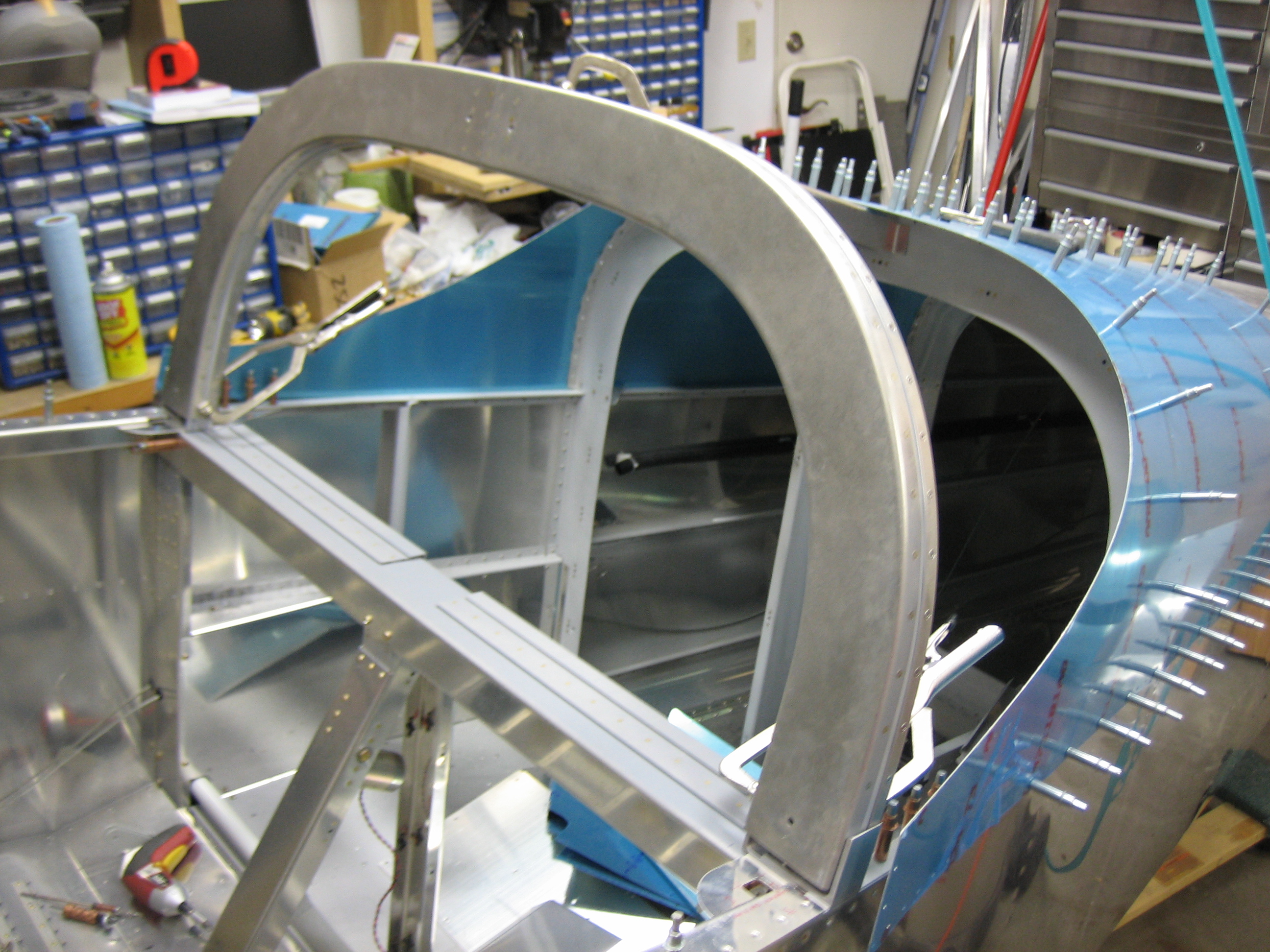
Here’s the cabin frame clamped as low as it can currently go.  It’s still about 3/16″ of an inch high right now, but I actually want it to end up a little high so I can get more headroom.  One of the engineers at Van’s said the cabin frame could be moved up at least 1/4″ without any problems.  I want to double check this before permanently mounting the cabin frame though.

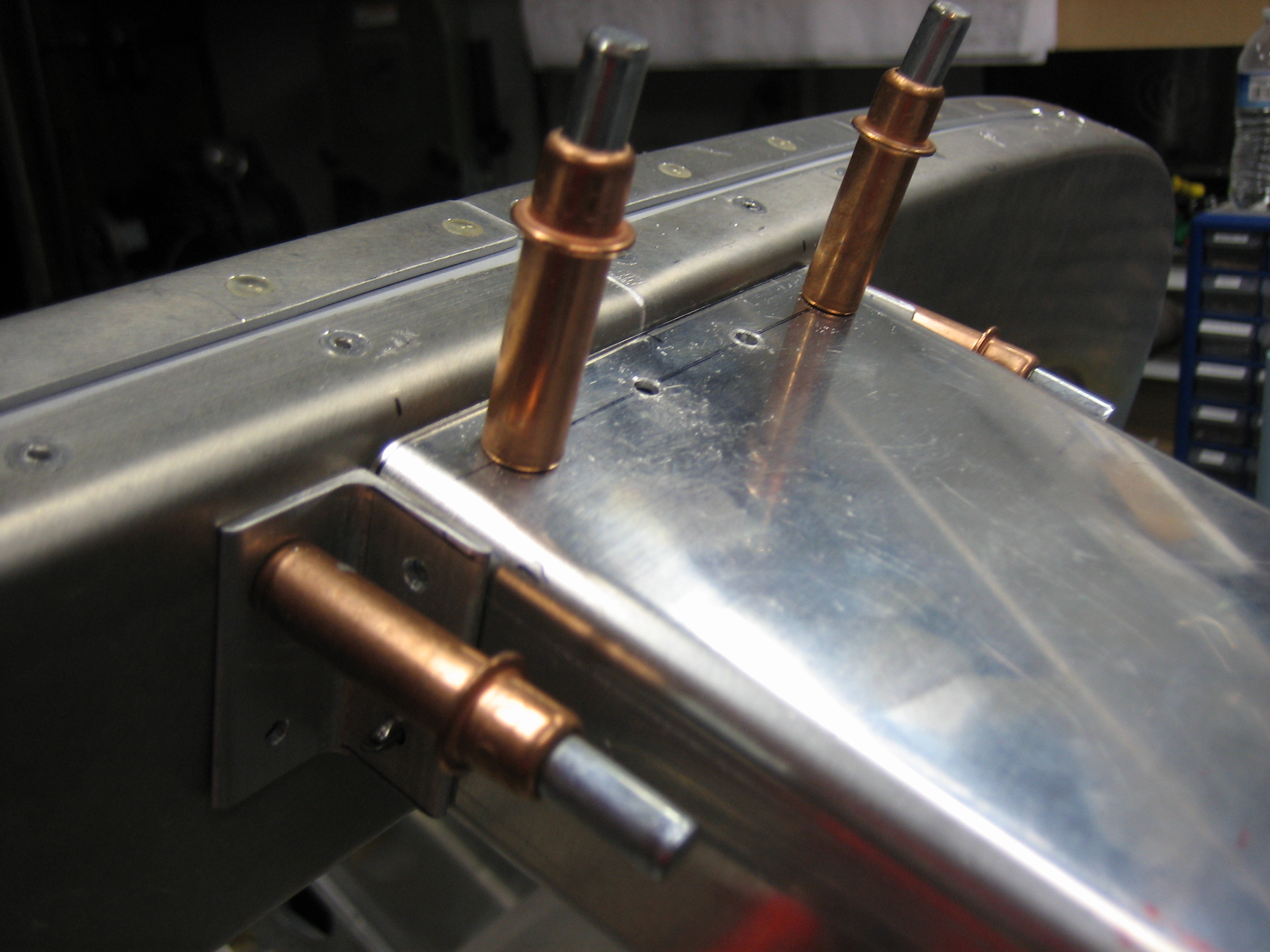
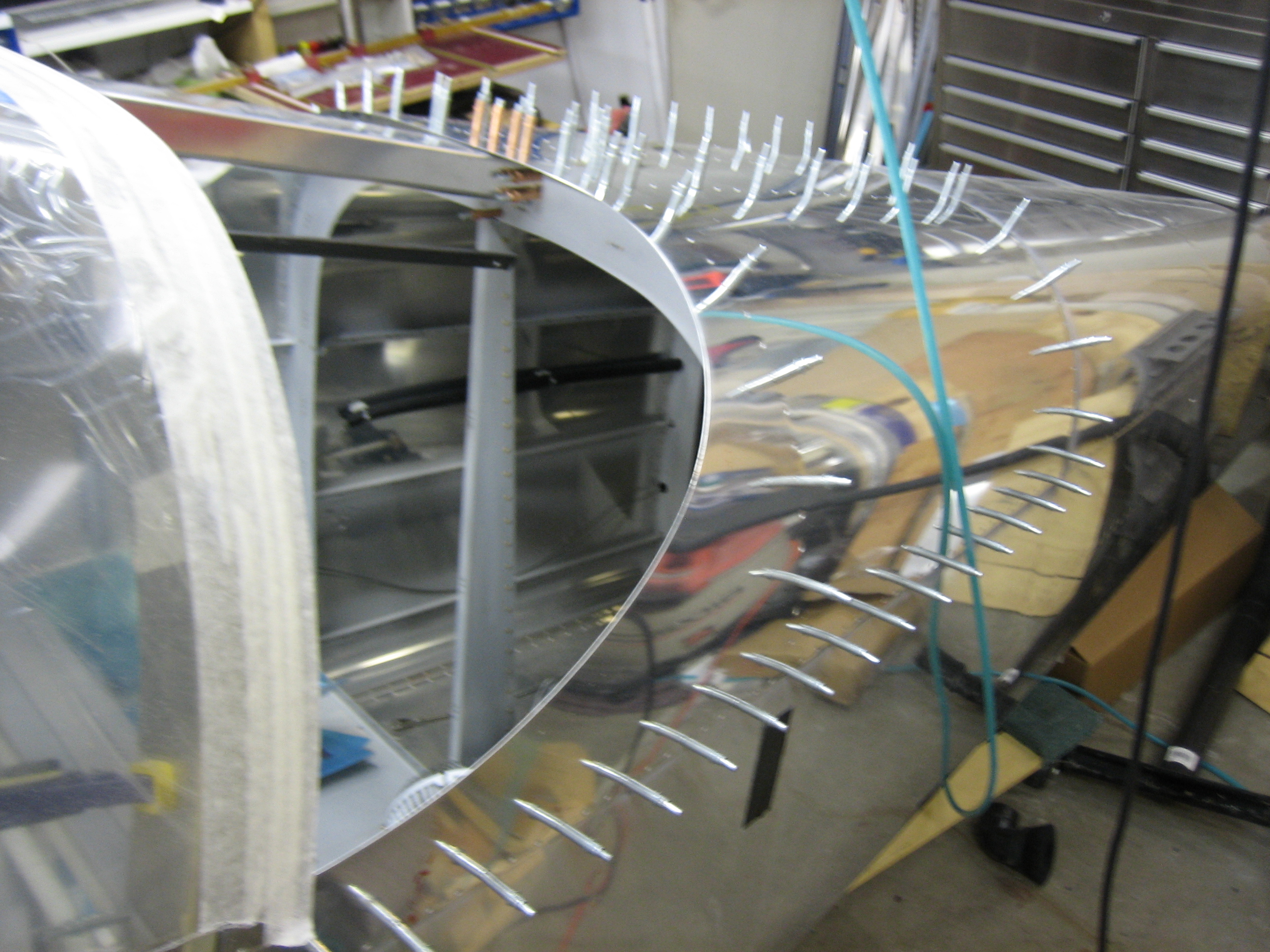
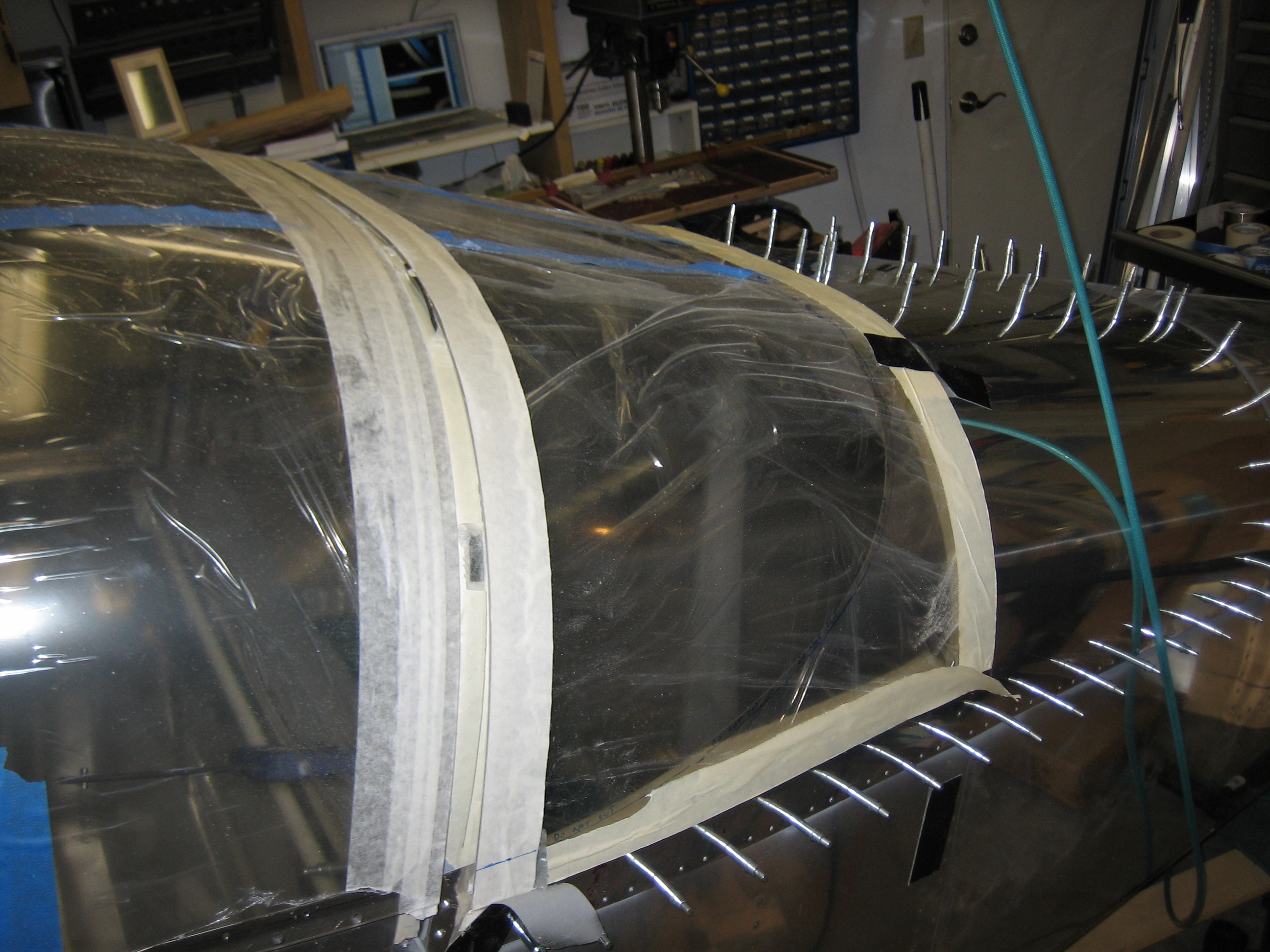
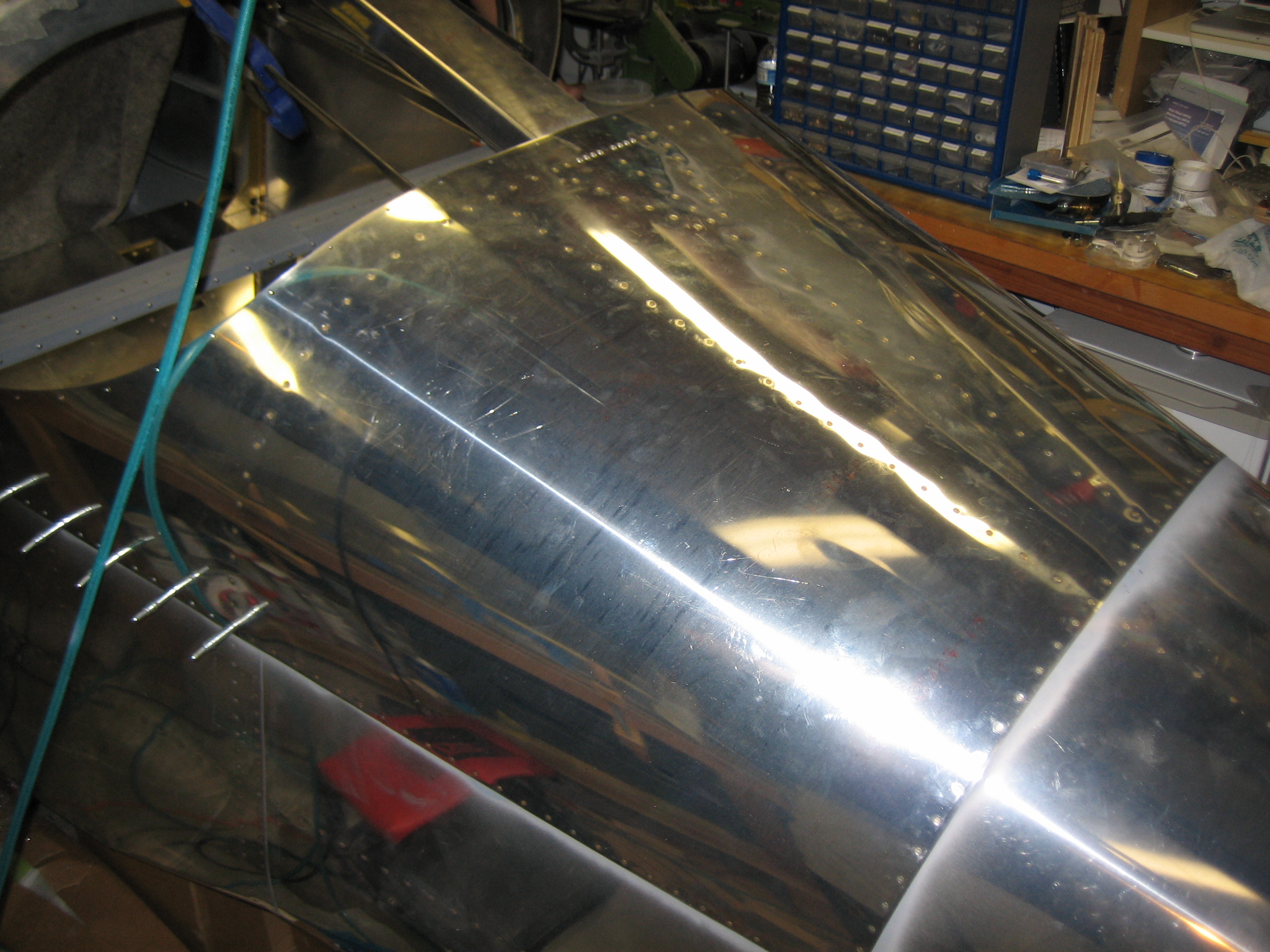
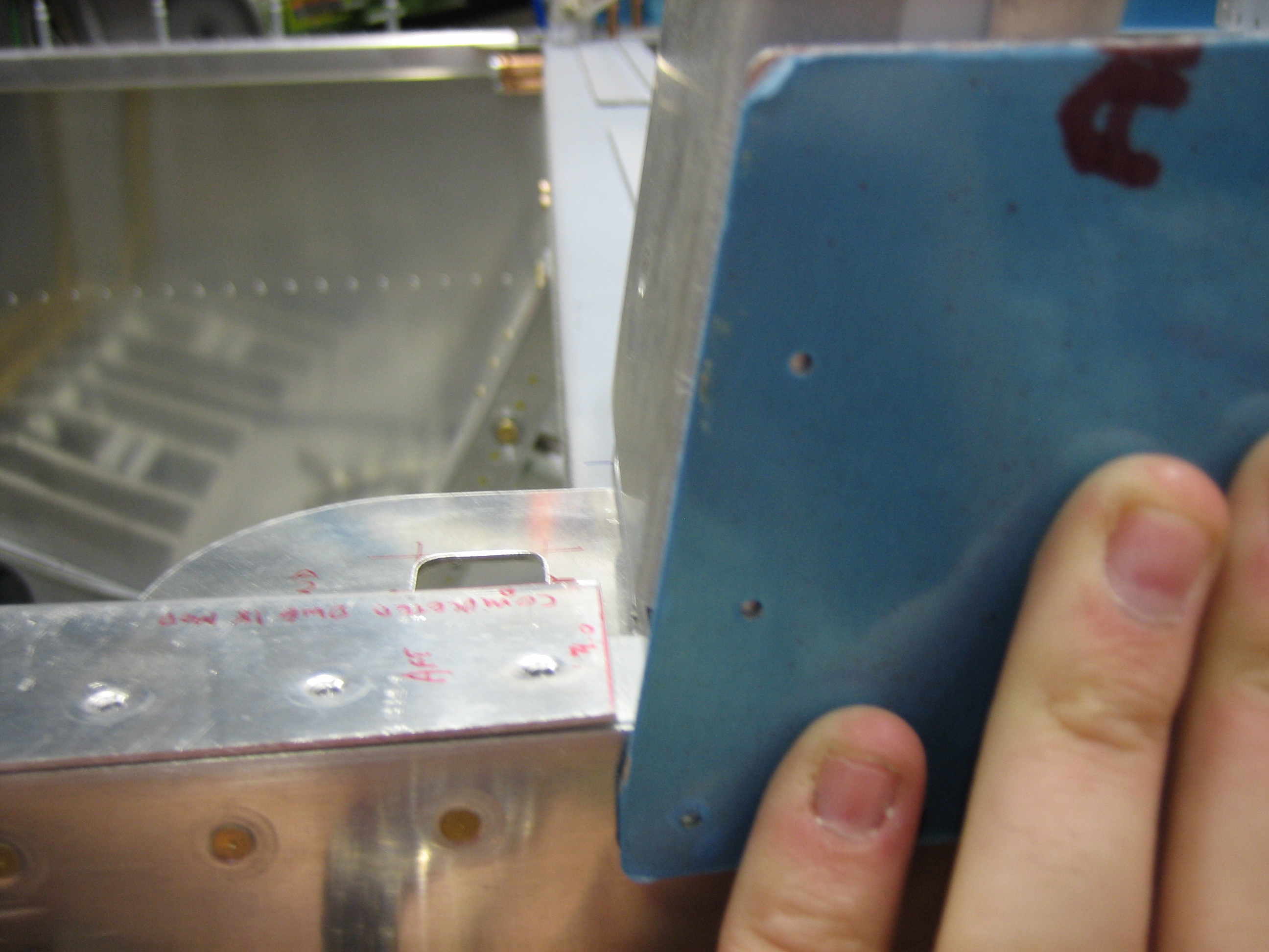
Here you can see that the side skin is perfectly aligned with the cabin frame (both angle and longitudinal position).

I also installed the cabin frame brace to correctly position the cabin frame.  It’s clecoed in the back, but only clamped in the front.  I don’t want to drill this until I’m sure of the position.

Lowered Cabin Frame

I had the cabin frame clamped 1/4″ above the location specified in the plans.  I looked over the canopy plans as well as all of the fastener positions.  This is the only issue I ran into.  The lower #8 screw through the aft top skin would penetrate the cabin frame only 3/16″ above the lower edge.  Since this hole needs to be drilled out to #29 and then tapped for a #8 screw, I didn’t think this was enough.  I couldn’t lower the cabin frame much without the outer edges running into the inner radiuses of the attach angles.  I didn’t get a picture of it, but I made a relief cut and radiused the edge to allow the cabin frame to drop down.

Here’s the cabin frame dropped to the height specified in the plans.  There’s now approximately 7/16″ edge distance on this hole which would be more than plenty.  I’m probably going to try and move the canopy up to the minimum edge distance for this hole to get as much headroom as possible.  A #29 hole is 0.136″ diameter.  1.5D edge distance would require 0.204 edge distance which is just over 3/16″.  If I increase that to 1/4″ to get a little more than minimum, then I’ll end up with a cabin frame about 3/16″ above normal.

Finished Attaching Cabin Frame

I ended up positioning the cabin frame exactly where the plans specify, 17 7/8″ up from the aft canopy decks.  After clamping everything securely in position and double checking the measurements, I started drilling.  First up is to drill the aft edge of the channel to the top skin and F-706 bulkhead as well as to drill the channel flanges to the bulkhead.

Next up is to layout the four holes that attach the channel to the cabin frame.  I drilled these to #40 first using the fan and then opened them up to #30.

I also drilled the side angles to the channel and cabin frame.

I used a couple of c-clamps to squeeze down the cabin frame where it had flared out near the bottom and was thicker than 1.5″.  I then drilled the forward holes through the side skins and through the attach angles and cabin frame.  These were initially drilled to #30 so that they could be clecoed.

I then laid out and drilled the aft holes.  These are drilled perpendicular to the cabin frame and then countersunk for a #10 screw.  The countersink is asymmetric because the attach angle curves to follow the longeron.  The countersink needs to be deep enough so that the screw is below the surface of the attach angle since the skin lays over the top of this screw.

The forward holes are then countersunk for a #8 dimple.  Notice that these holes are drilled perpendicular to the face of the attach angle, not perpendicular to the cabin frame.  This is because a screw will screw in here and it needs to be flush with the skin.  The aft holes need to be perpendicular to the cabin frame because there will be a nut installed on the inside and it needs to be flush with the inside face of the cabin frame.

After countersinking the forward holes, I opened them up to #29 and then tapped them with an 8-32 tap for a #8 screw.

Finally, I drilled the inner holes for AN3 bolts and installed some scrap AN3-5 bolts.

Here’s the whole cabin frame with all attachment points complete.

Worked on Cabin Frame Channel

I primed the mating surfaces and riveted on the forward cabin frame channel attach angles.

I also countersunk the doubler and riveted it onto the channel using the forward holes.  The aft holes will tie these pieces to the top skin and F-706 bulkhead.

I cut out the cover that I’m fabricating for the channel and drilled a series of holes with a #19 bit for #8 screws.

I riveted on some countersunk nutplates and screwed the channel cover on.  Here it is reinstalled in the plane.  I’m going to install a light here that can be used to illuminate the interior both in flight as well as during loading/unloading.

Fabricated ADAHRS Mount

I decided to take a break from the canopy and fabricate the ADAHRS mount for the Dynon SkyView ADAHRS box.  I looked at several builder’s sites about how other people have done this and settled on a U shaped piece hanging between the center rib and left stringer.  I decided to add some bends along the edges though to stiffen the structure.  It’s approximately level in both axes right now, but I need to fine tune it slightly before drilling the holes though the rib and stringer.

I made the box deep enough that I could put two ADAHRS boxes (stacked vertically) in here if I decide to do that.

Worked on Canopy, Rear Window, and Final Tail Skin

Using a belt sander followed by some hand sanding, I trimmed the aft edge of the canopy to the line I marked earlier.  There will be some slight additional sanding to open up the gap between the forward and aft windows once everything is locked in position.

Andre stopped by and we knocked out the deburring and dimpling of the final tail skin.  I was hoping we’d get this riveted on today, but we ran out of time.

Later in the evening, I came out and roughly positioned the rear window.

I marked the edge of the window and wrote “Do Not Cut” all along the line to ensure I wouldn’t accidentally cut along this line.  The window has to overlap the skin about 5/8″ to provide room for the screws that attach the window to the skin.

As the plans specify, I initially trimmed the window to 1 1/4″ beyond the window edge.  This allows the window to slip under the skin.

Drilled Rear Window and Riveted Aft Top Skin

I centered and clamped the rear window in place using the 1/8″ spacers along the top of the cabin frame.  I’m using these because I’m gluing the rear window to the cabin frame with sikaflex.

Starting at the center, I alternately drilled down both sides with the 1/8″ plexi bits.

Now that the rear window is in its final location, I put some tape along the marked line.  I’ll trim this back to this point and will then probably sand both the forward and aft windows to open the gap up to the recommended amount.

My buddy Andre stopped by and we knocked out the riveting of the final aft top skin.  I left the forward ears unriveted since I need to disassemble and paint a bunch of the interior components before everything is put together for good.

Powder Coated Tailwheel Components and Fuel Tank Brackets

I stopped by my buddy Corbin’s house to use his large powder coating oven.  We powder coated all of the tailwheel components as well as the fuel tank brackets that mount to the fuselage.

The powder coat looked perfect on every part except for the weldment that ties the tailwheel bracket to the spring.  Our guess is that they used some oil or other lubrication when press fitting the brass bushing into the steel weldment.  This oil ran out during baking and caused the finish to fail.  I’m going to clean this off and try again.

Worked on Cowl Joint

I loosely installed the fuel tank support brackets, mostly to get the brackets off my bench and out of the way.  These will need to be tweaked to align with the fuel tank brackets once the wings are mounted, so there is no sense torquing these bolts down right now.

Back to work on the upper cowl, I broke out the die grinder and cutoff wheel and cut out the opening for the oil door.  This needs to be removed now so that you have access to the inside of the cowl when fitting the upper hinge pin.

I cut out a 13″ diameter disk of hardboard to use in place of the spinner.  I also cut a spacer that is the height of the firewall that is keeping the aft edges of the cowl the right distance apart.  Even with the joint pulled tight and the flange around the disk as narrow as possible (without looking out of round), there are still small gaps on the outside edges.  I’ll end up having to use some flox to make these joints tight.  I also laid a straight edge across the center to see how straight all of the joints are.  They’re ok right now, but I’ll need to sand these with a long straight edge to get them perfectly even.

Finished Powder Coating Tailwheel Components

I re-powder-coated the part that didn’t come out right last week.  The problem turned out not to be lubricant leaking out between the steel and brass components.  In fact, I had simply not cleaned out all of the grease from the inside of the weldment.  When it heated up, it flowed out and ruined the finish.  I ground off all of the powder coat and cleaned it inside and out before redoing it tonight.  Afterward, I assembled all of the components.  This will stay on the shelf until the prop comes back off.