Fabricated Pushrods

I fabricated a couple of the pushrods used in the control system.  The shorter one ties the two sticks together in roll.  The longer one transfers the pitch forces from the sticks to the elevator bellcrank.  I still have to fabricate the pushrod that connects the elevator bellcrank to the elevators.  I primed them (including the inside of the larger one) with the rattle can primer since the inside of the fuselage is not exactly a high moisture area.

Finished Fabricating Center Cover, Worked on Controls

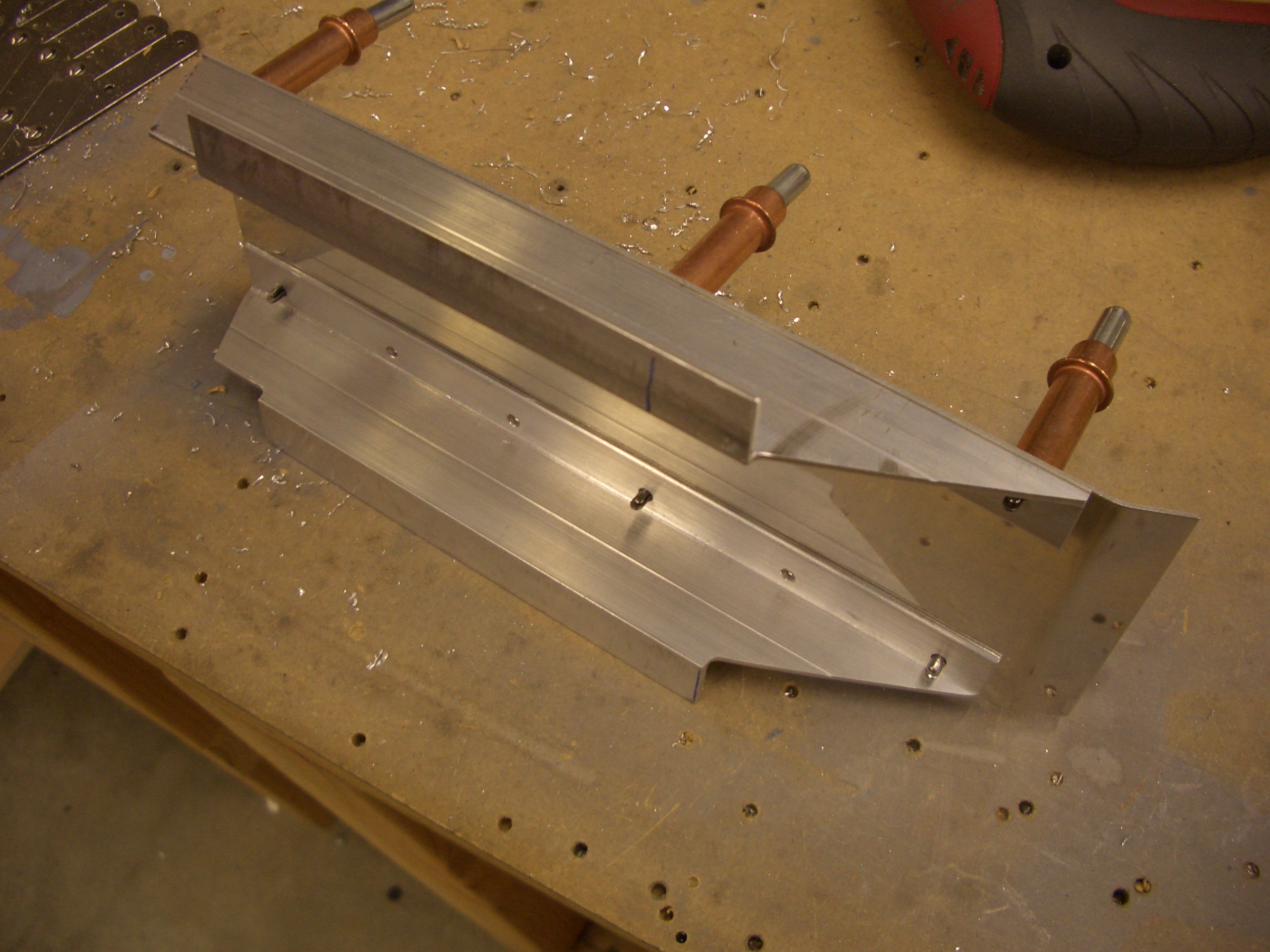
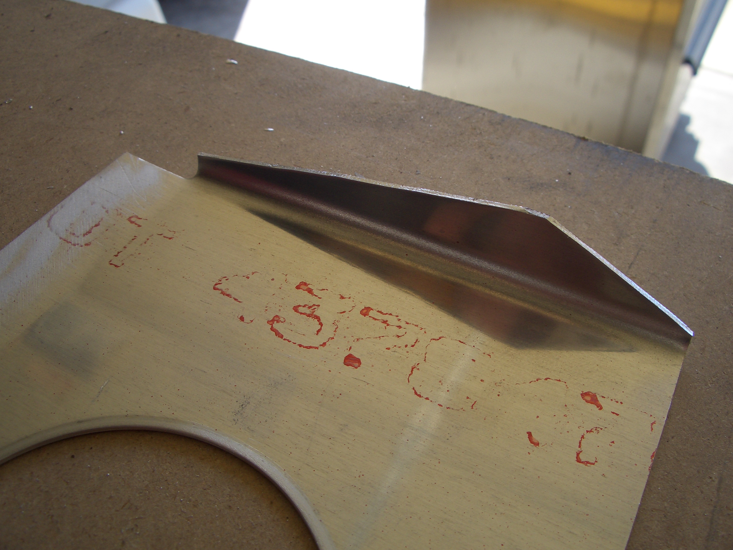
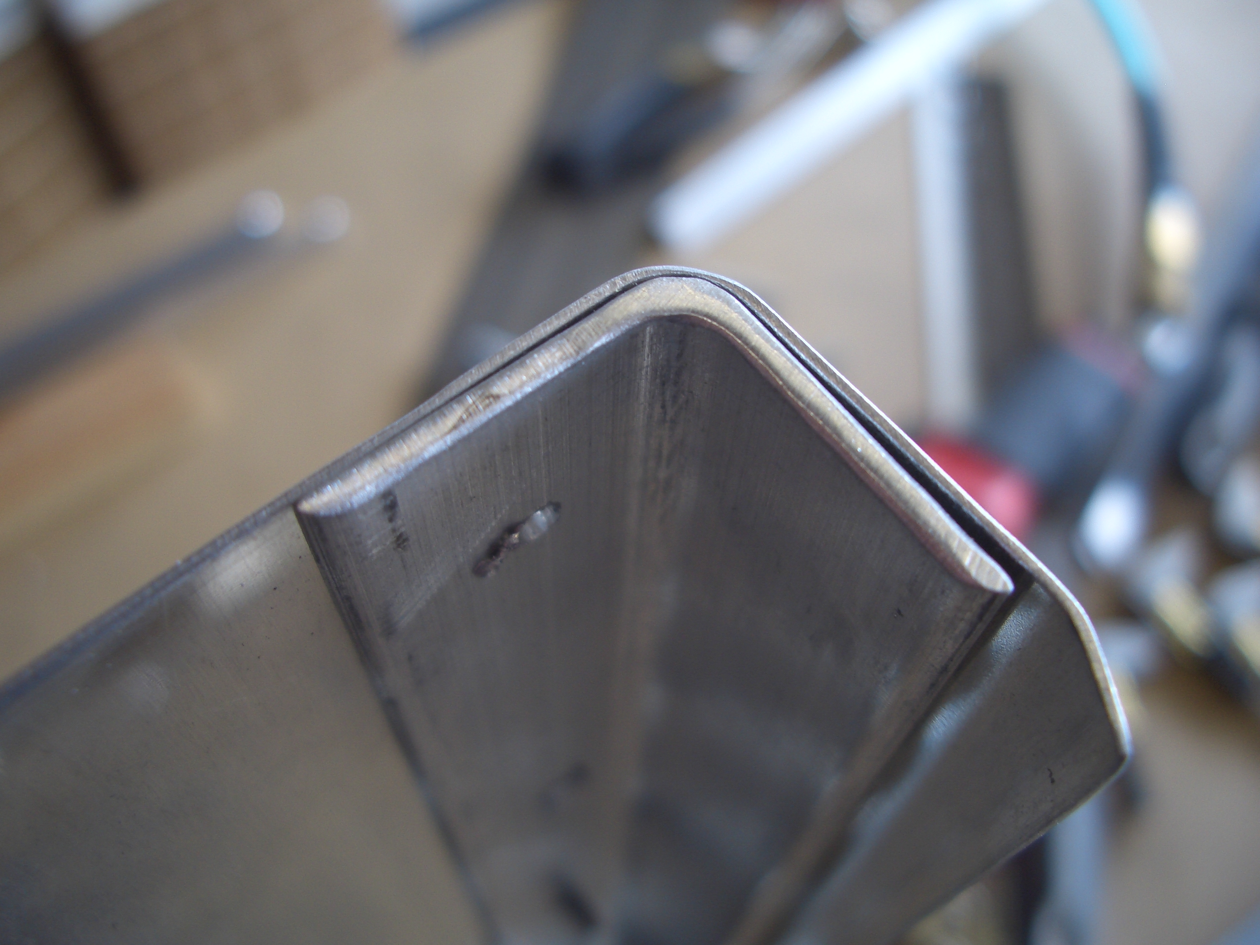
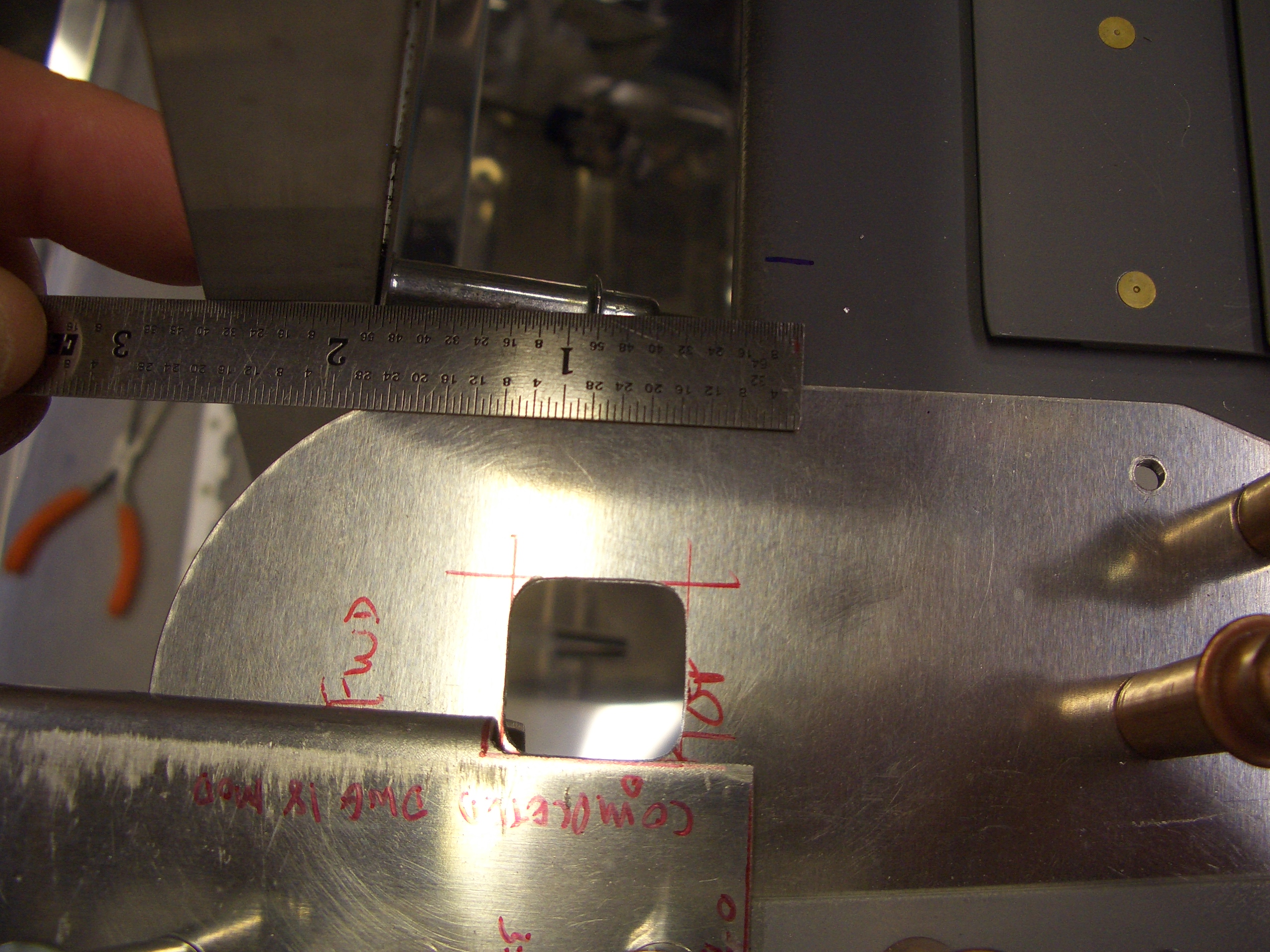
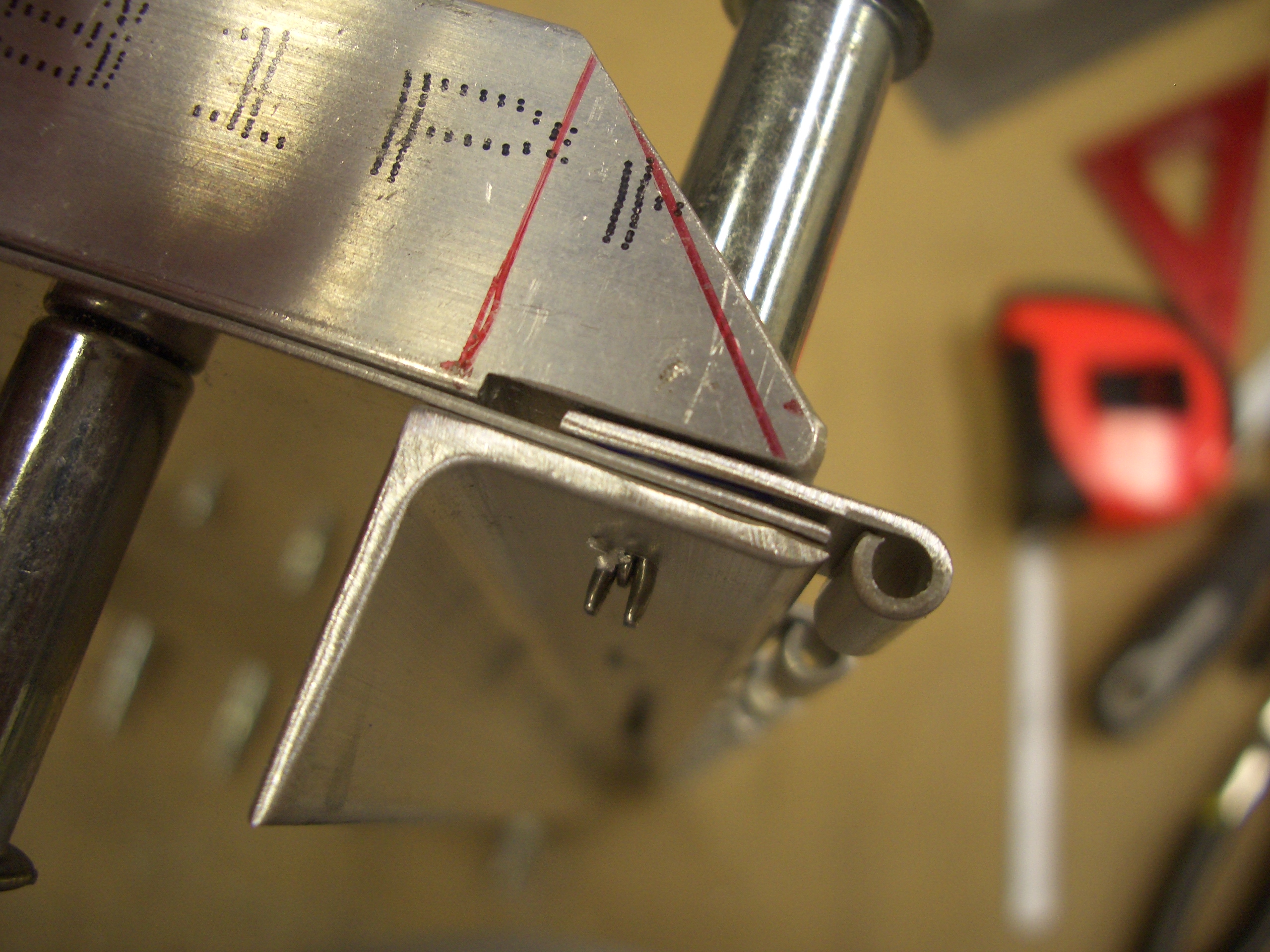
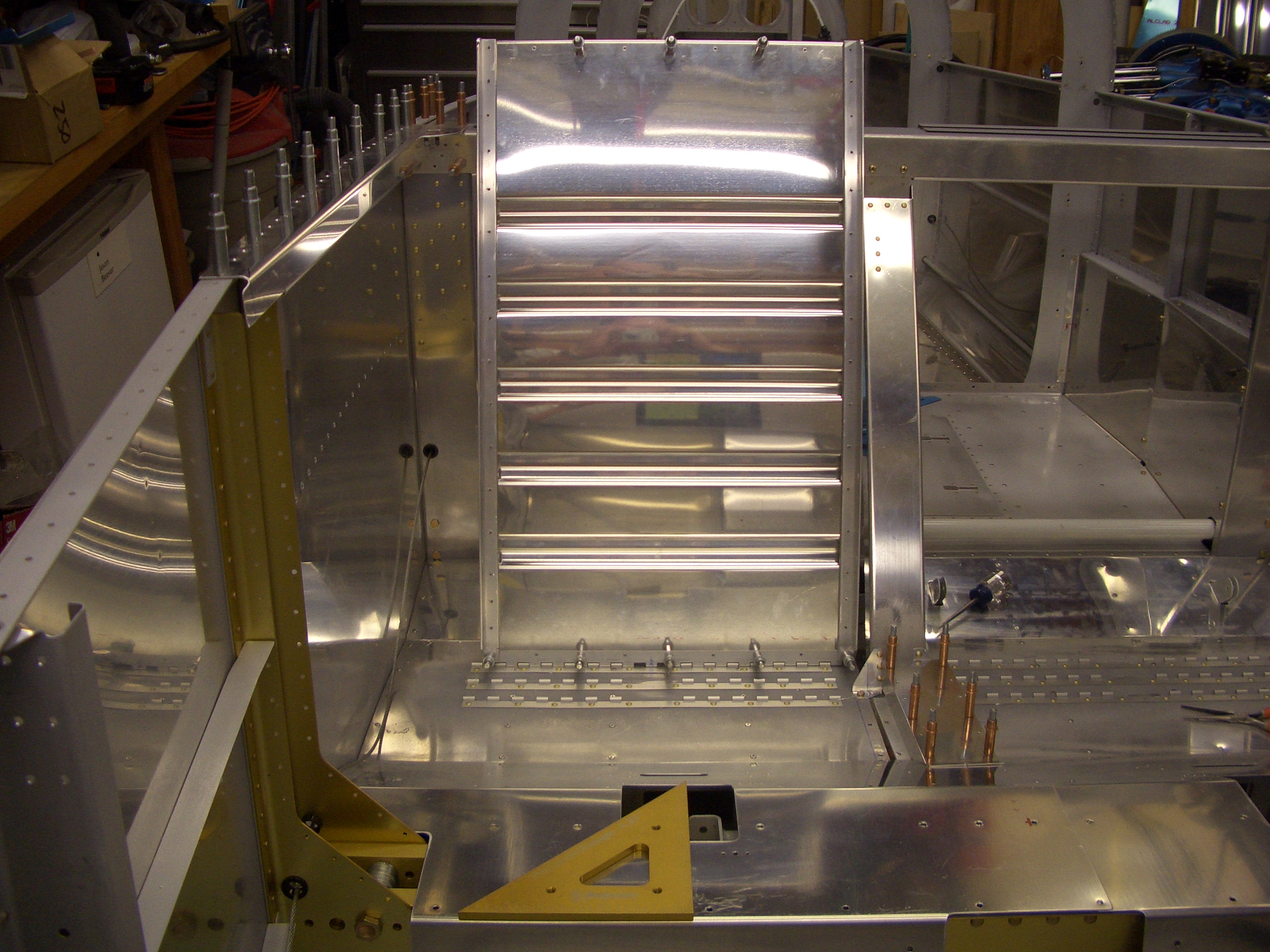
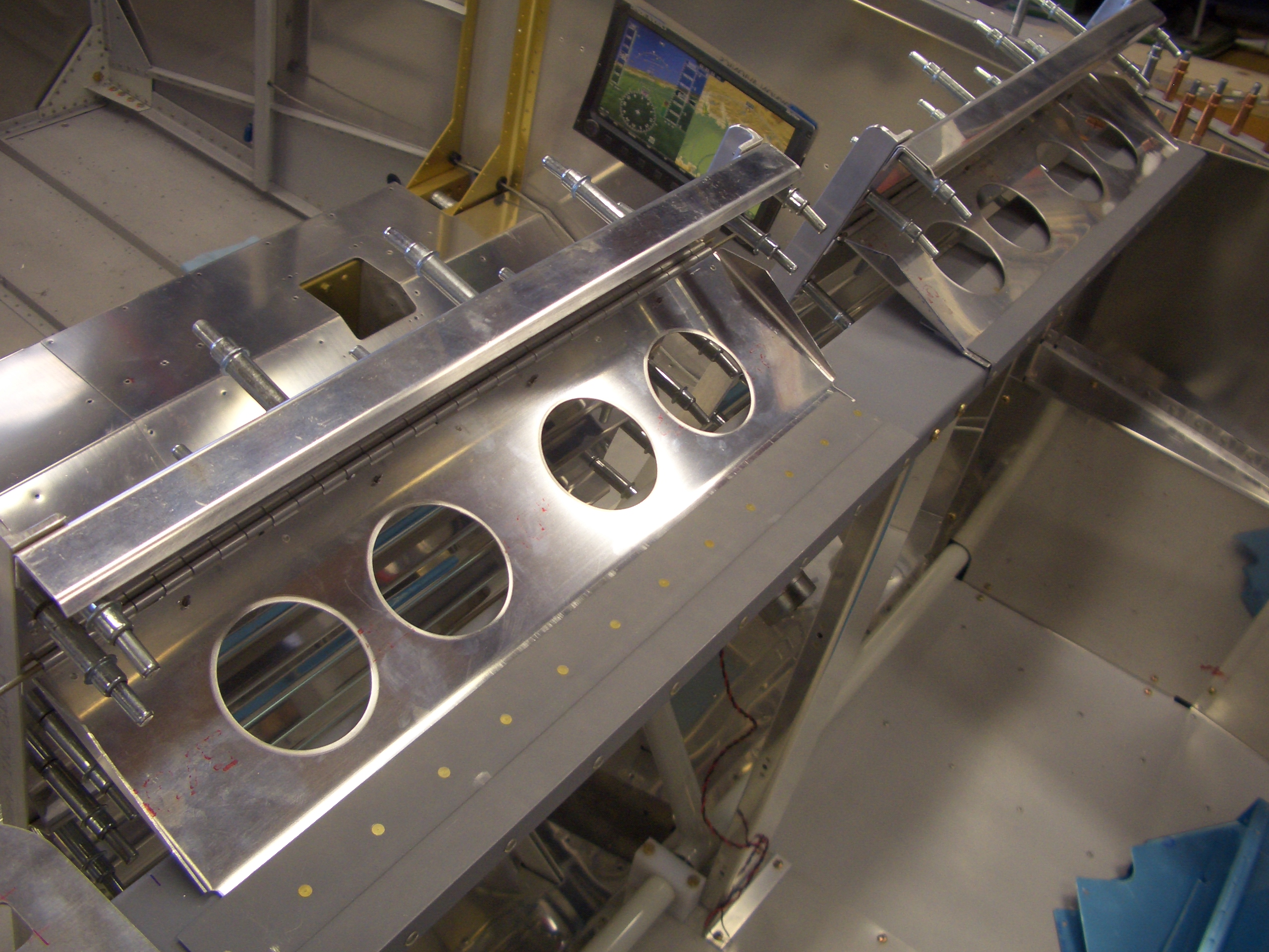
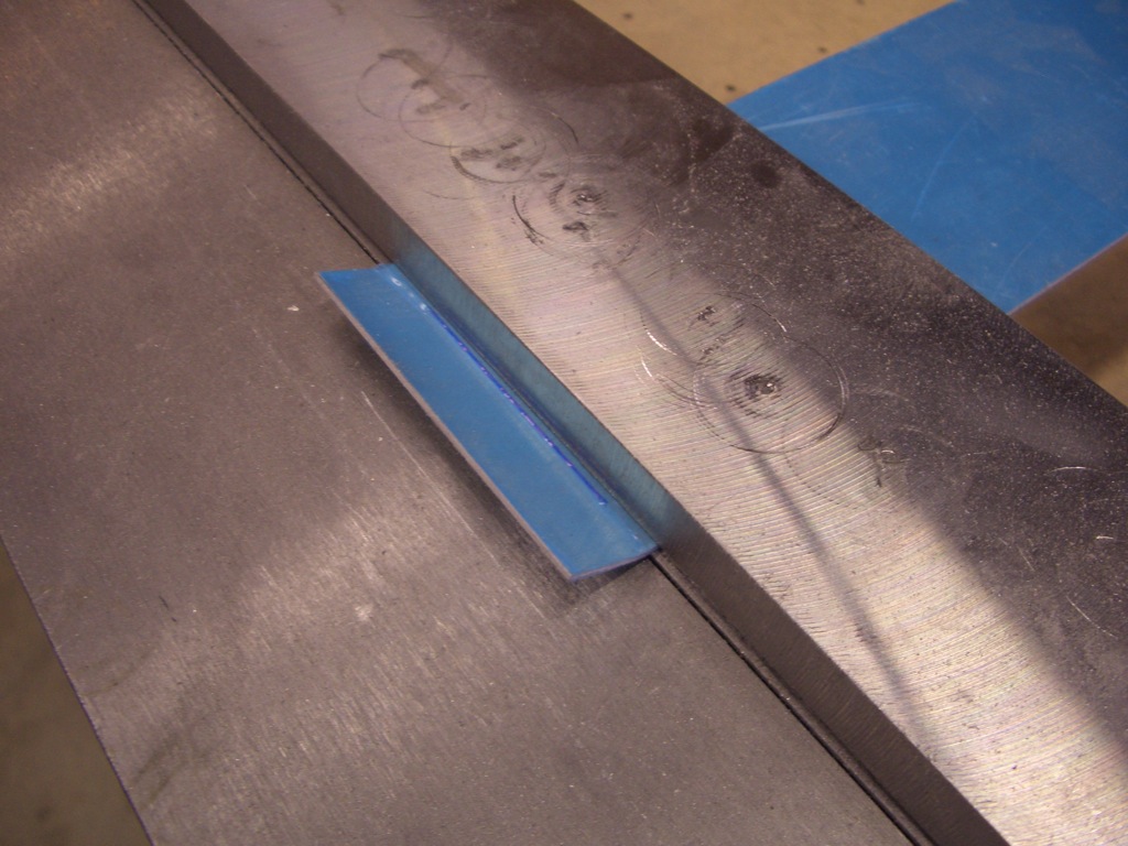
I bent the forward edge of the center cover top upward to match the slope of the forward seat pans.  This bending brake has come in handy for a lot of things in the build.

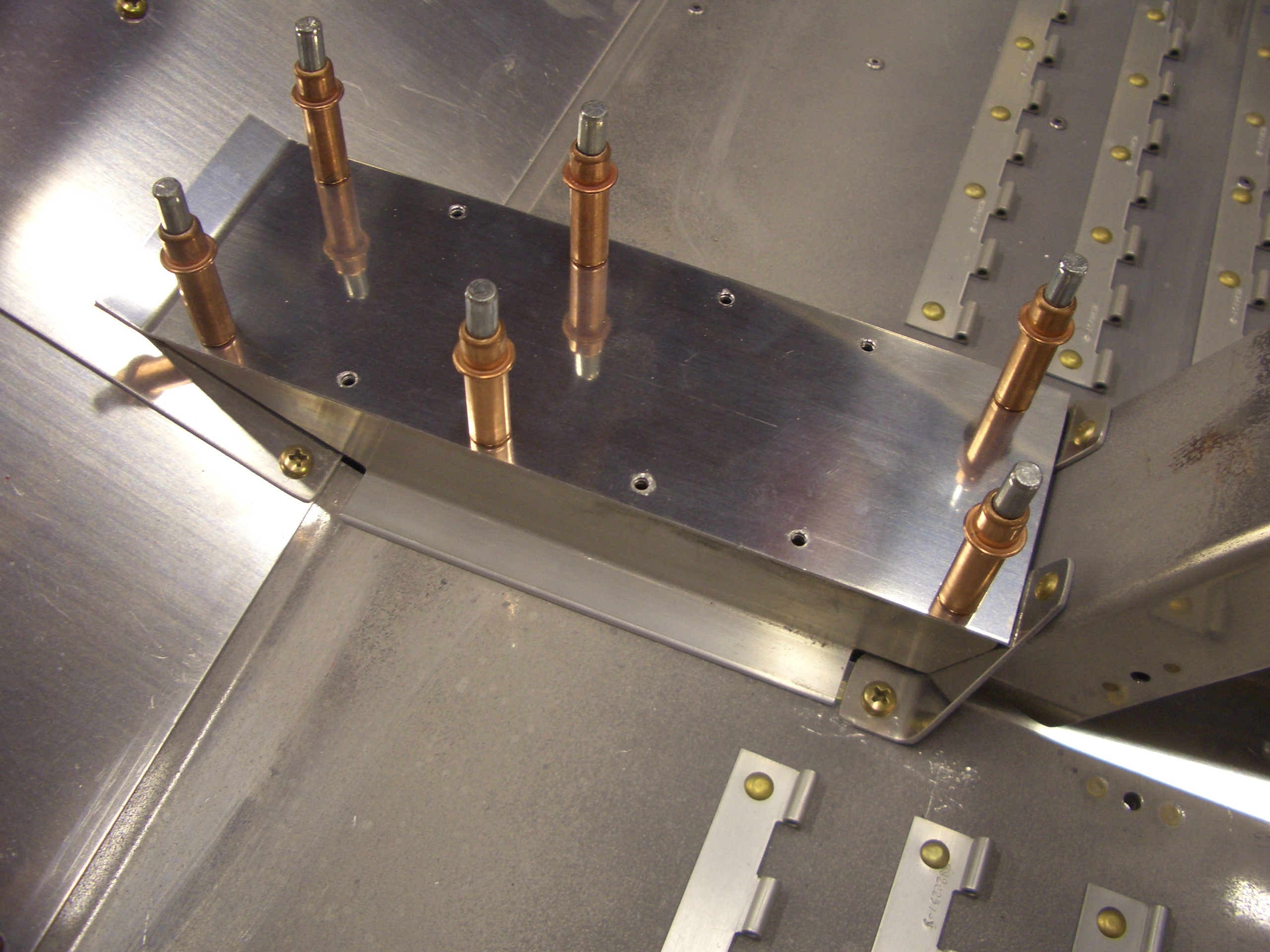
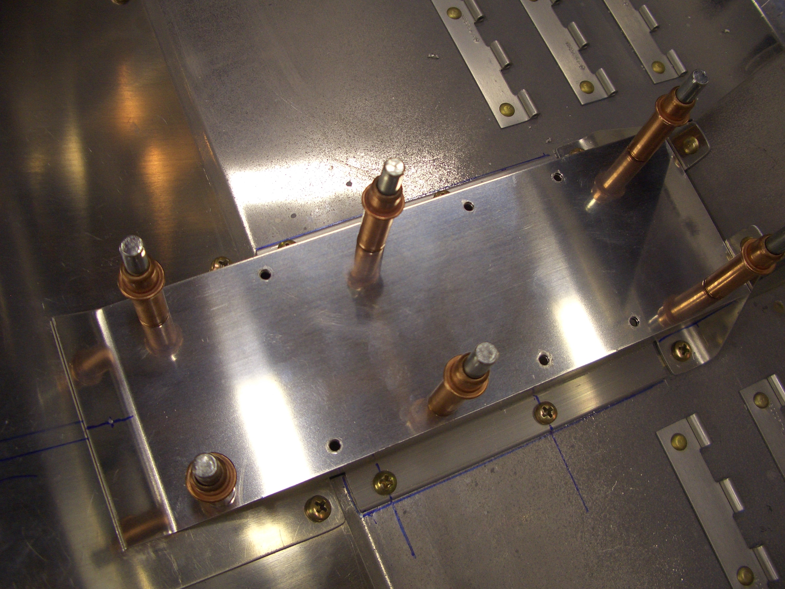
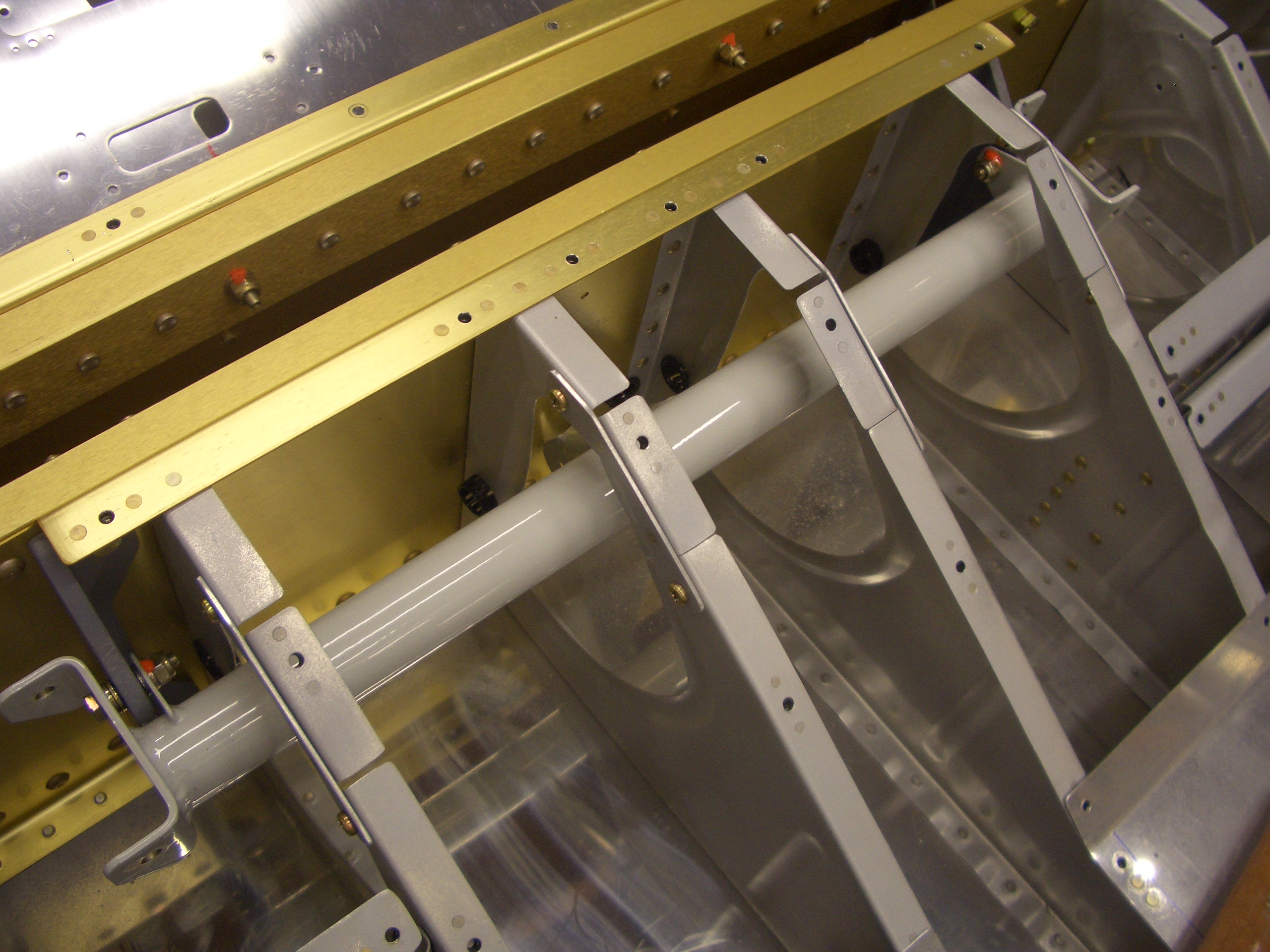
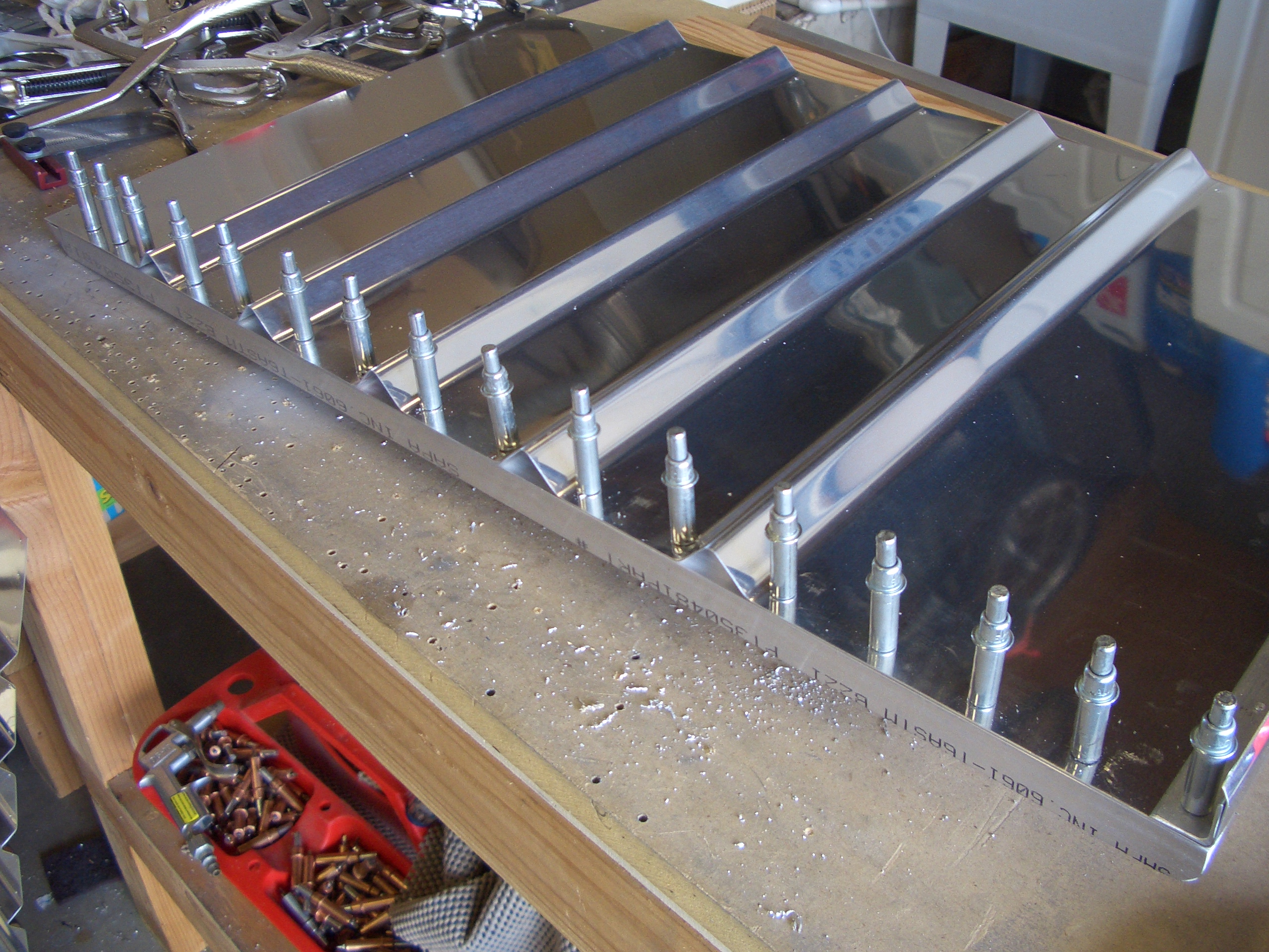
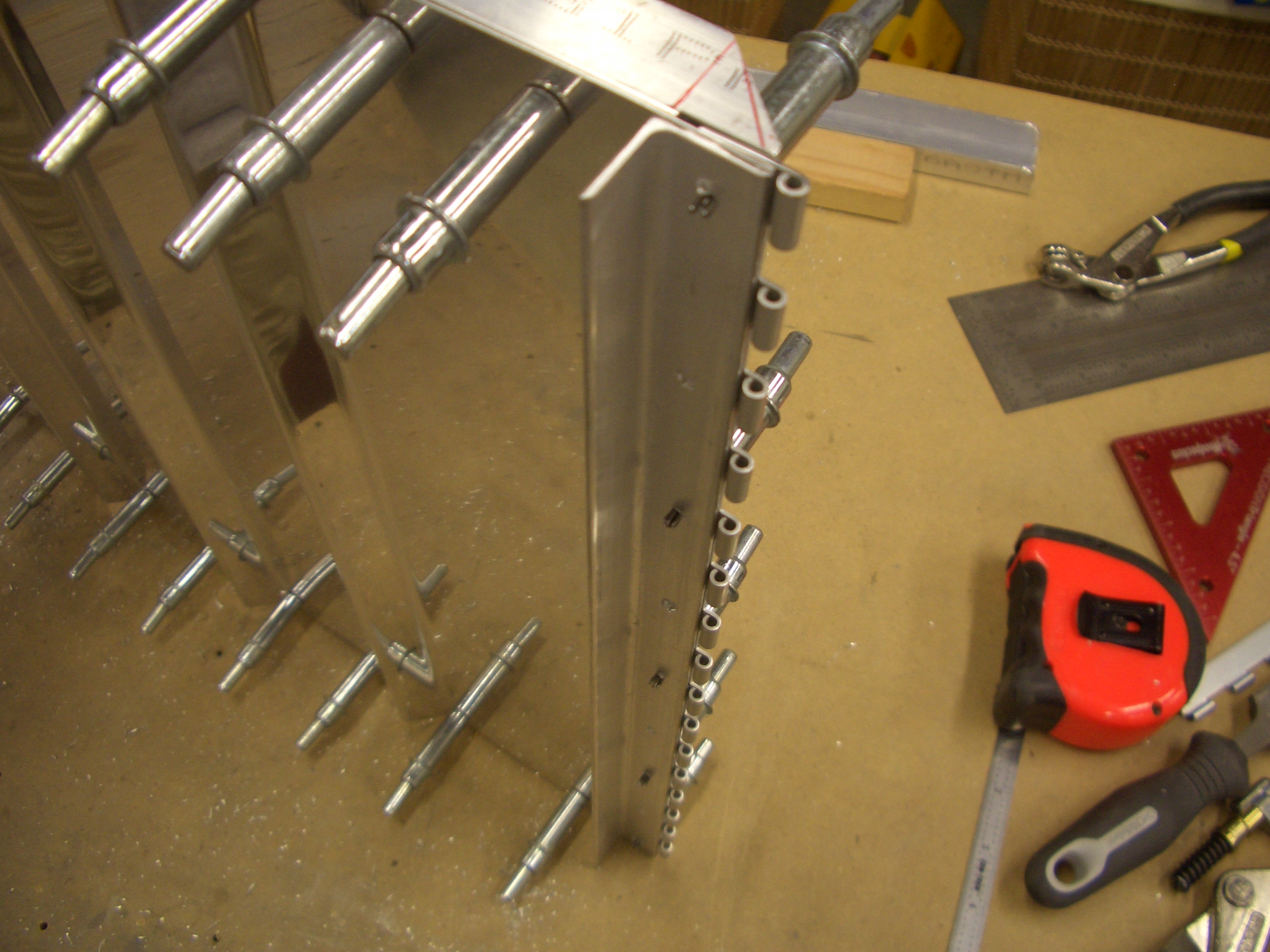
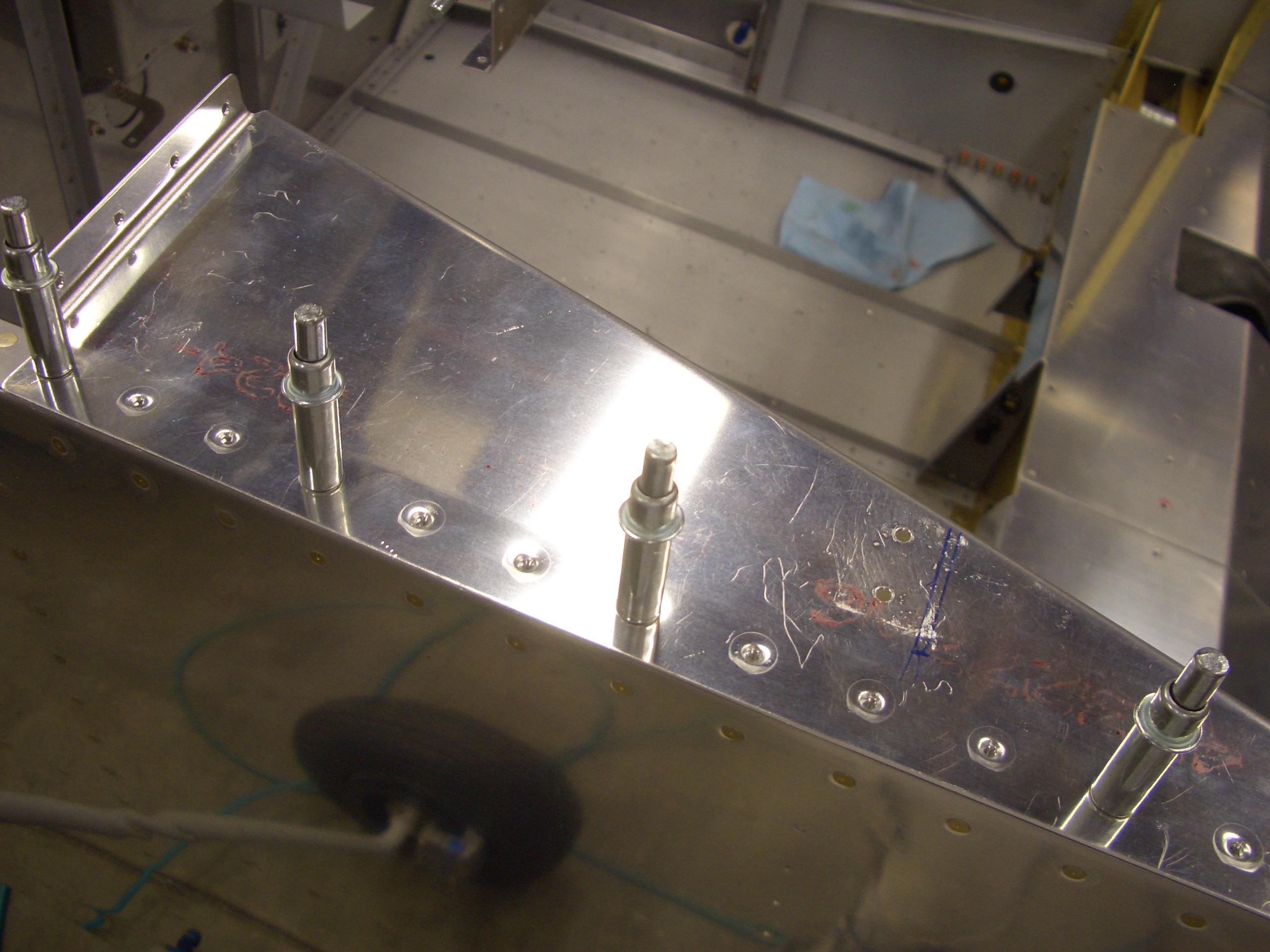
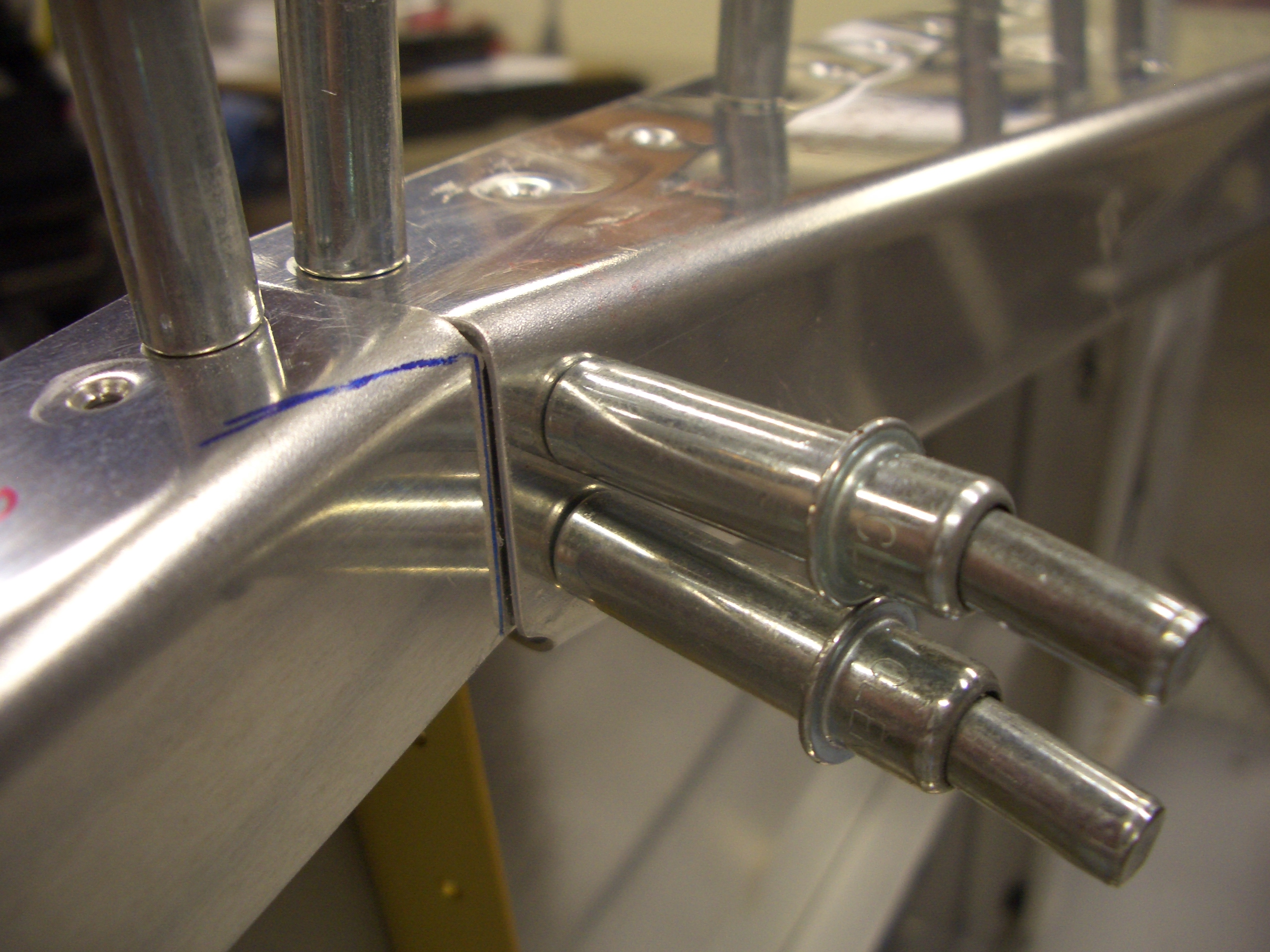
I drilled the top to the side z channels.  I intentionally drilled the top to the channels prior to drilling the channels to the floor so that I could ensure the top edges line up perfectly with the apex of the channels.

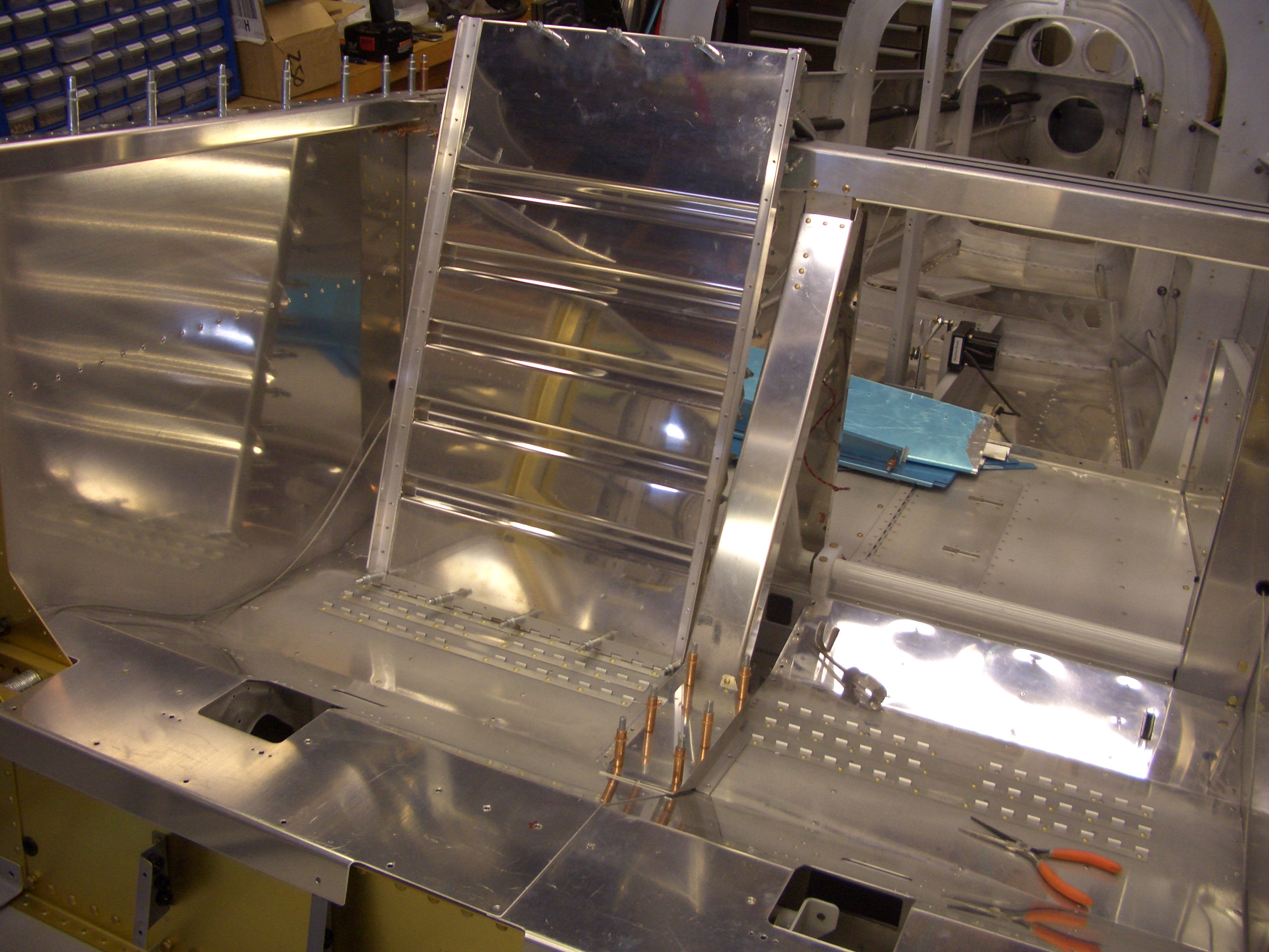
I had to sand/file away almost 3/8″ from the back edge to get this to fit down flat against the floor.

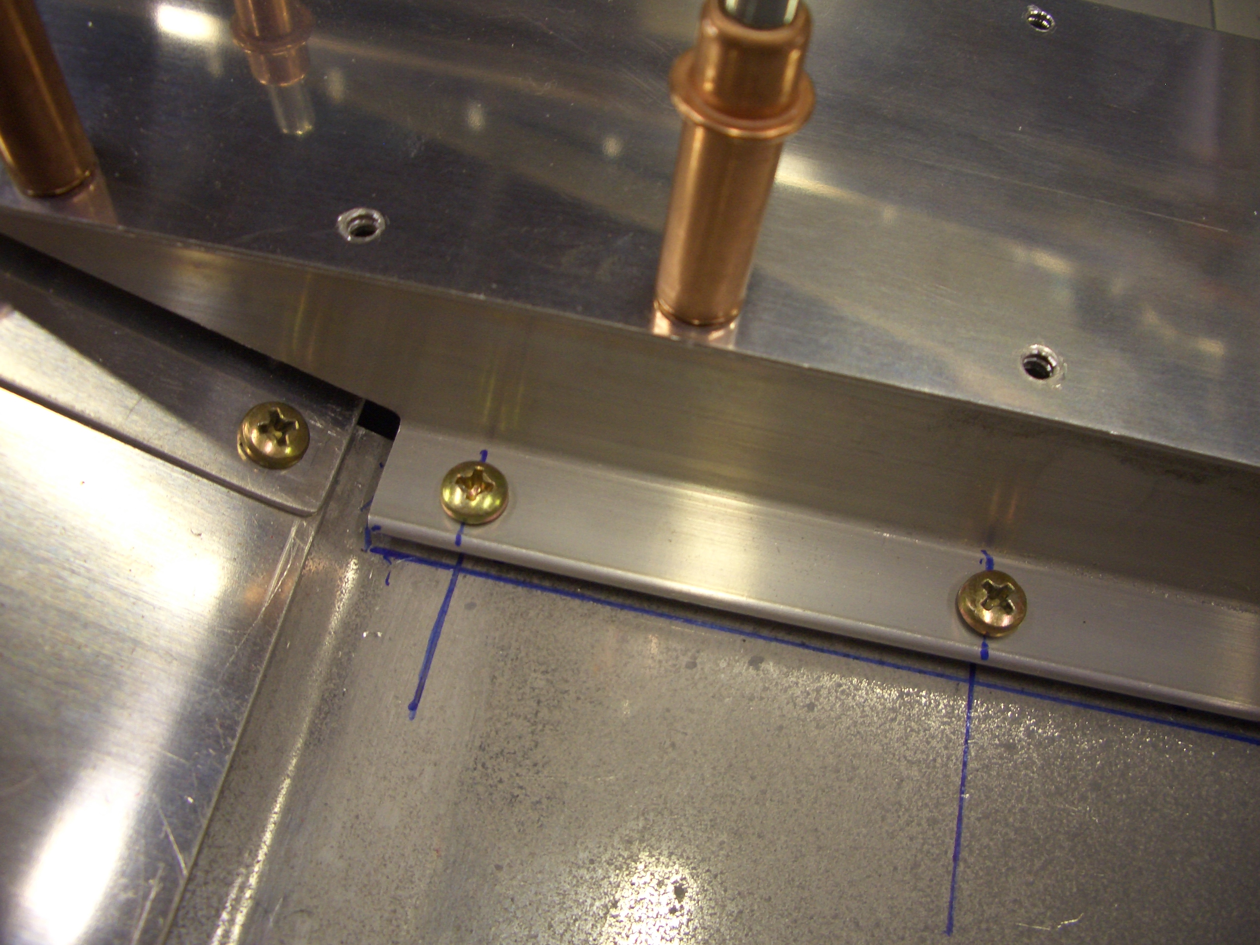
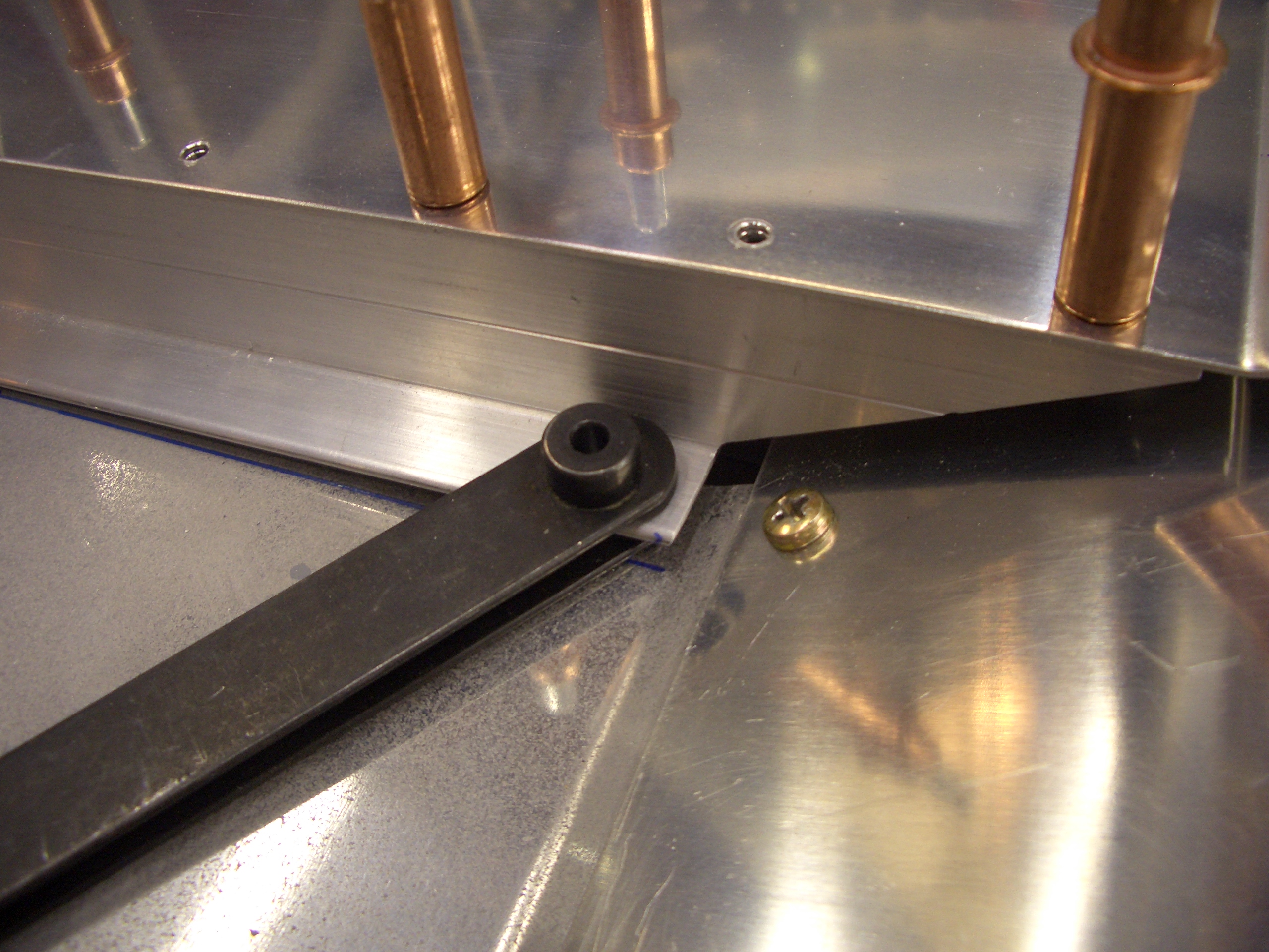
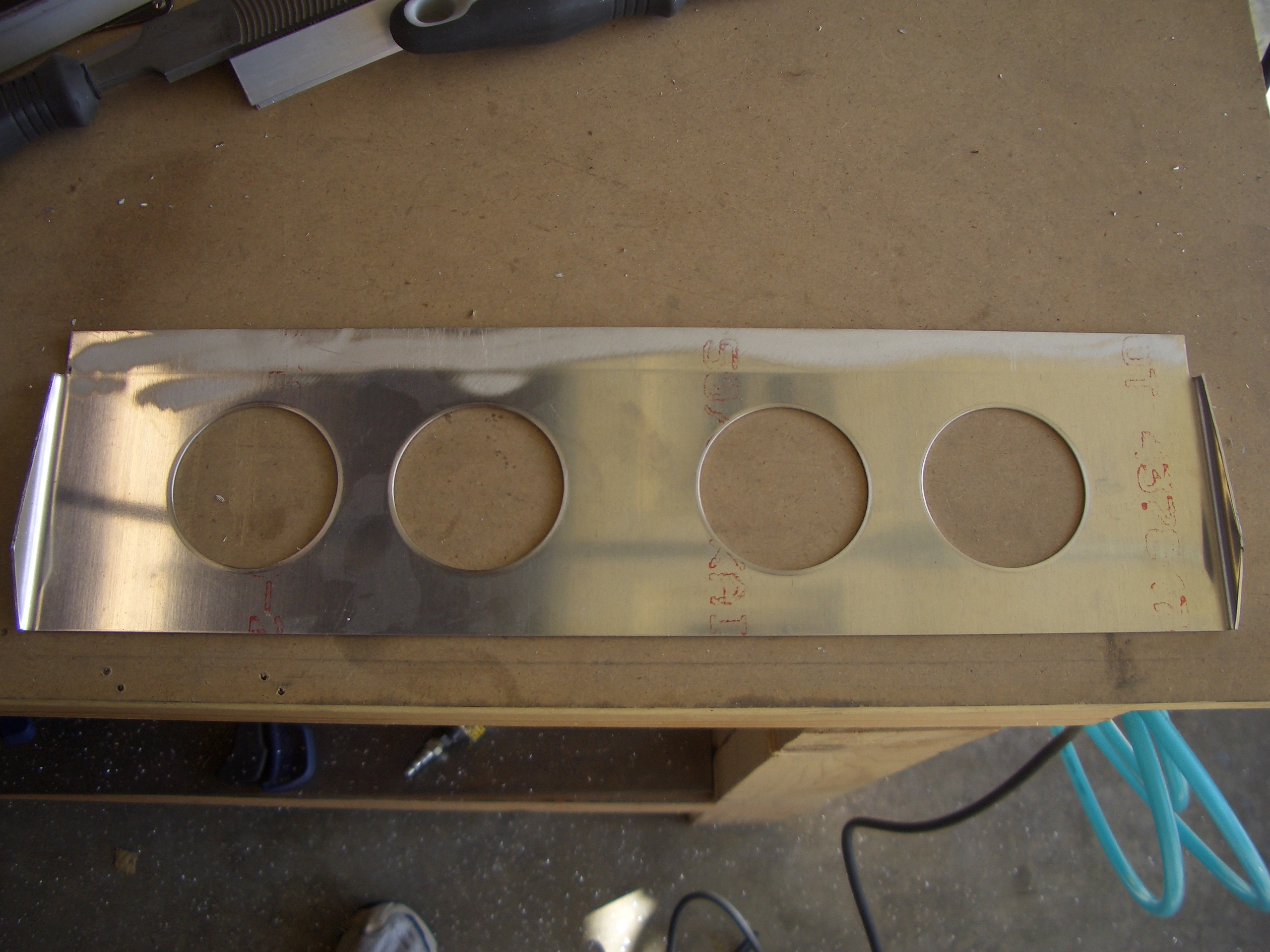
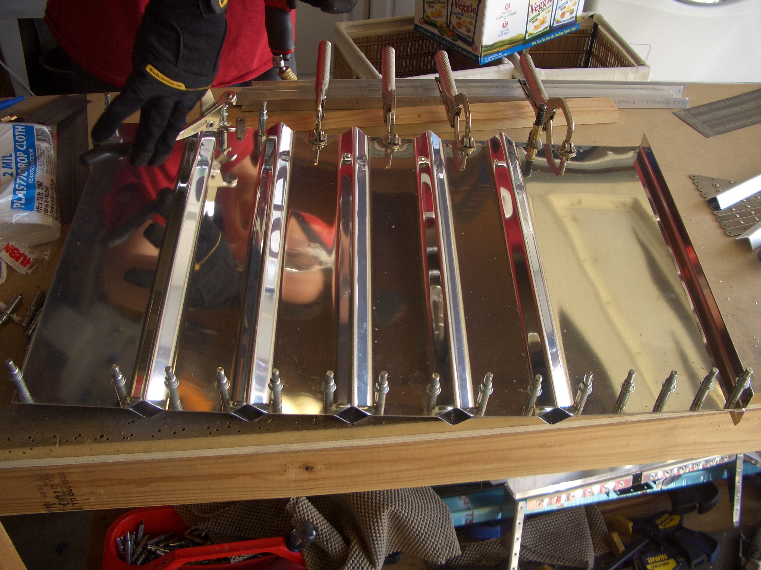
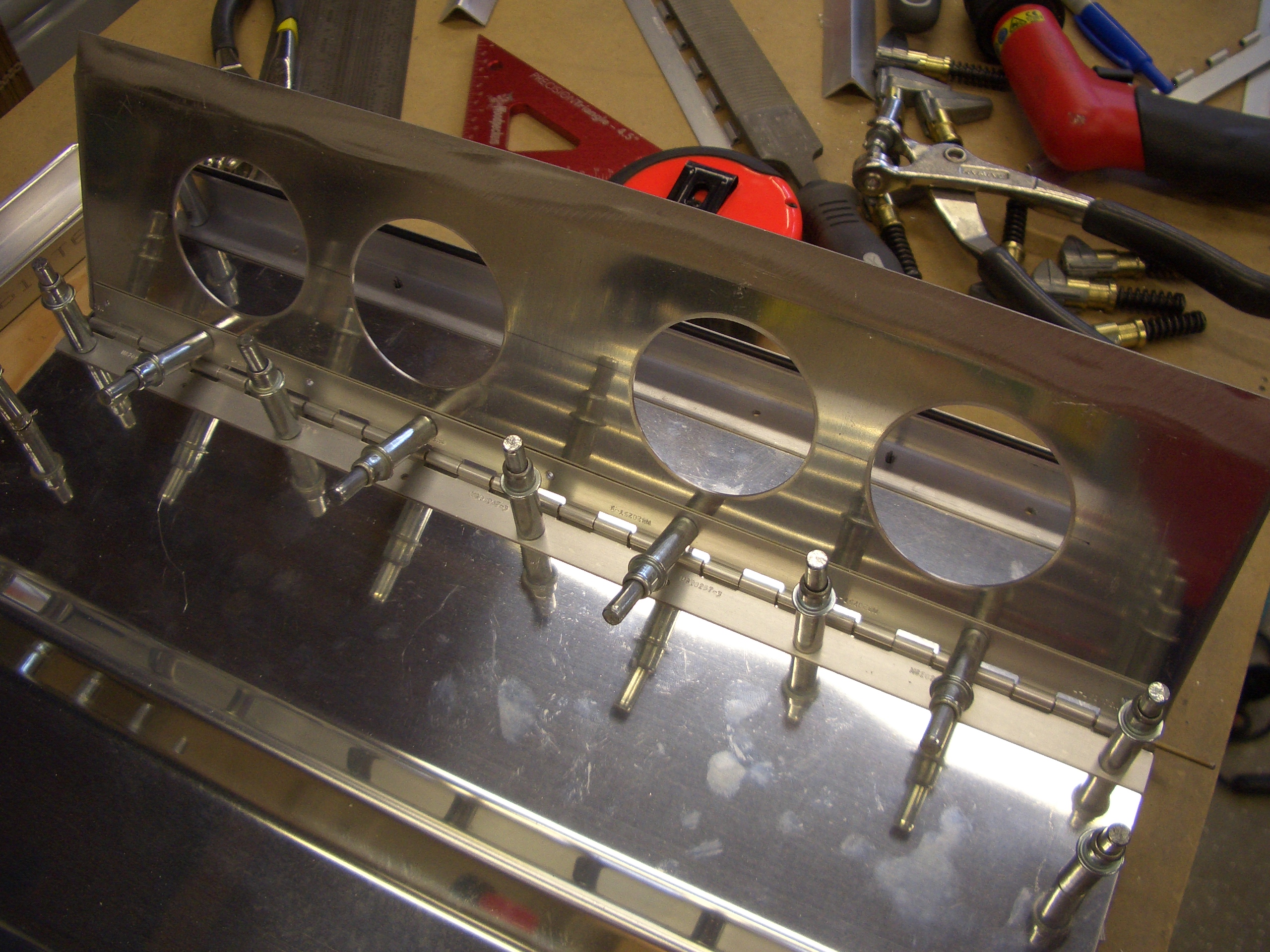
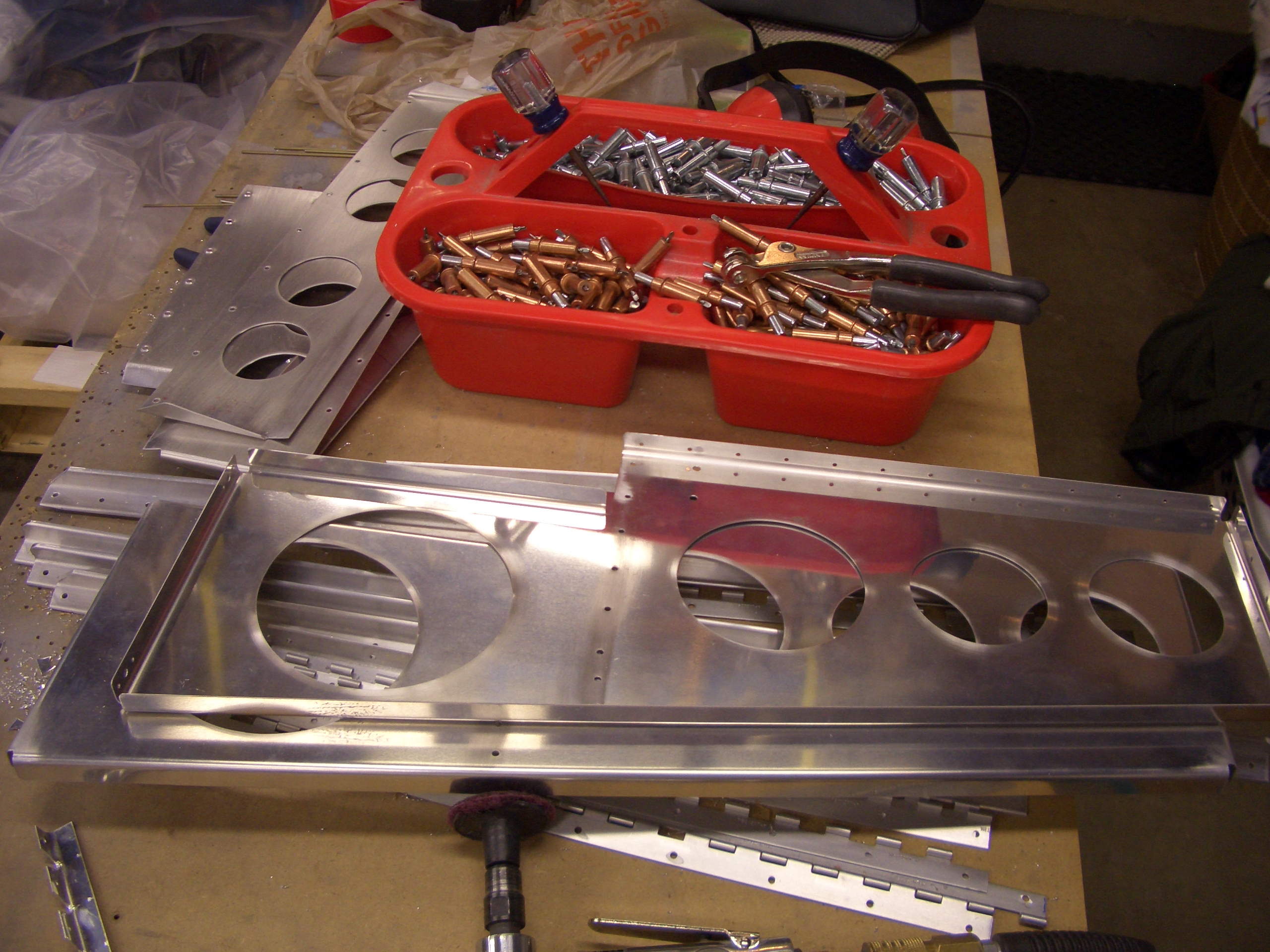
I laid out and drilled the holes on one side of the cover.  I drilled some screws in part way so that the z channel is up about 1/32″.

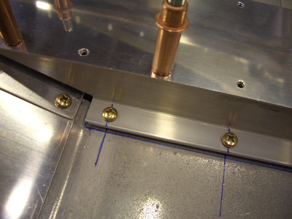
This keeps the cover level while I use a strap duplicator to match drill the other two holes.

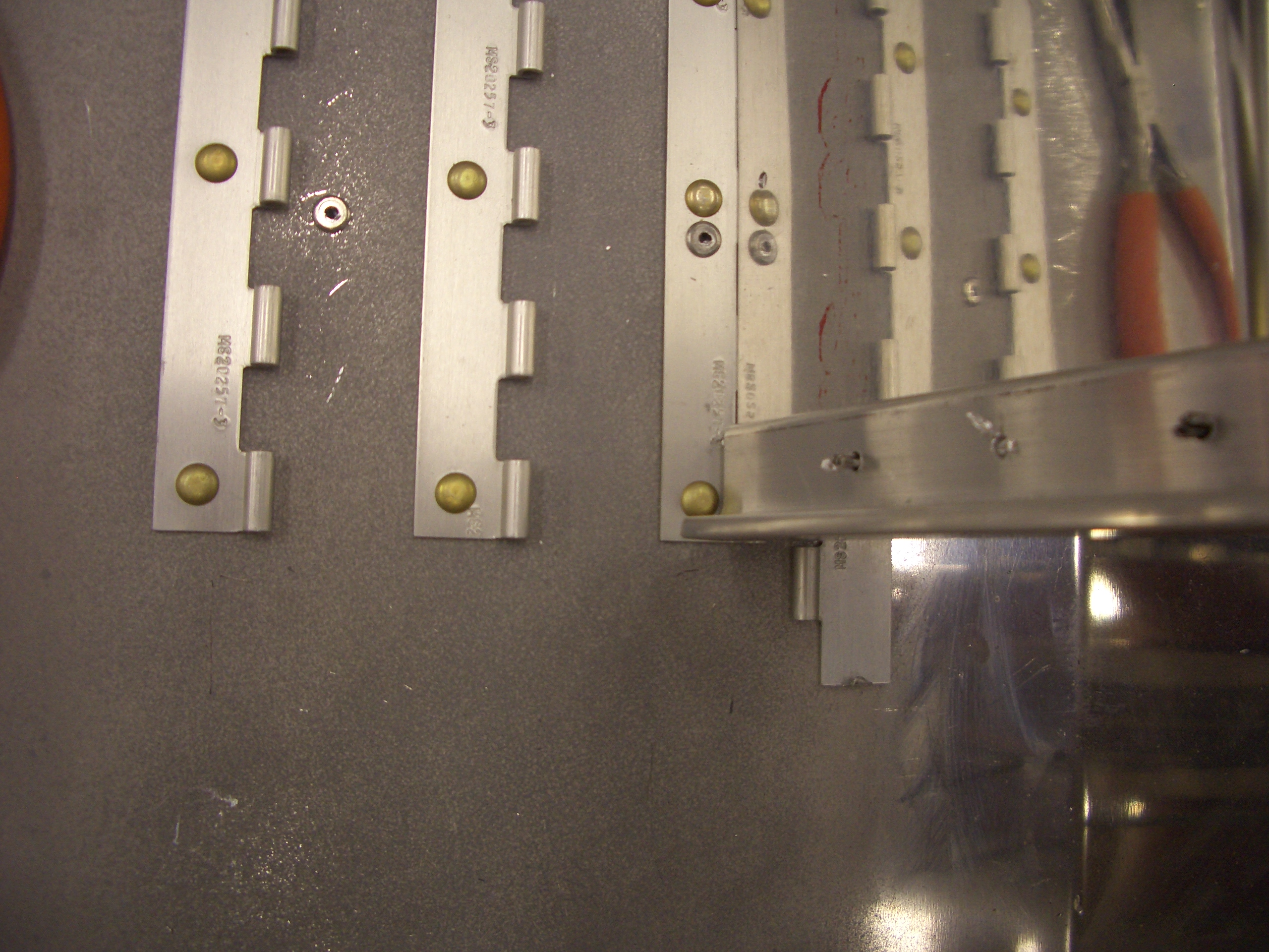
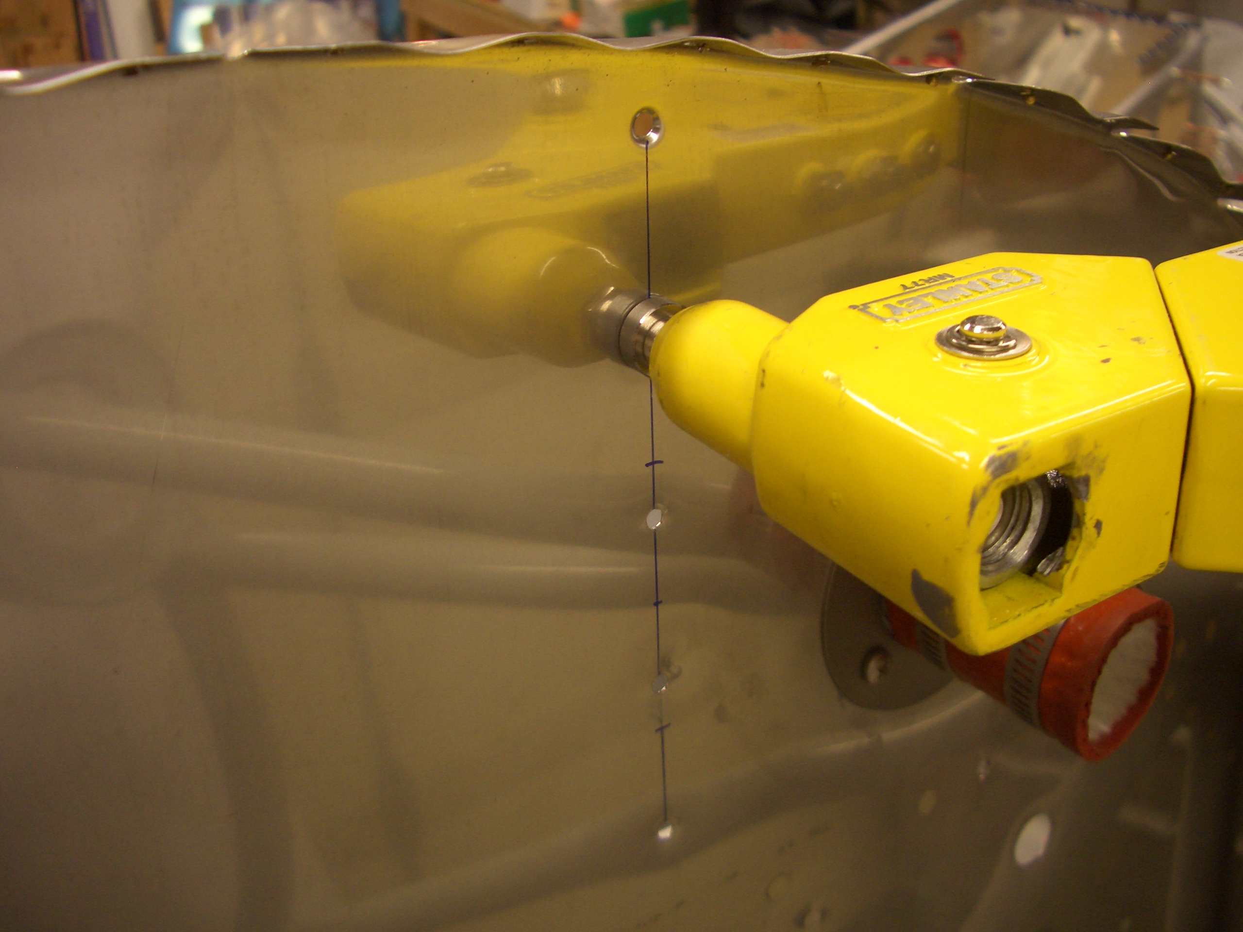
After screwing the cover down tight against the floor, I drilled an additional #8 hole in the turned up end that will allow the cover to be screwed to the forward seat pan.

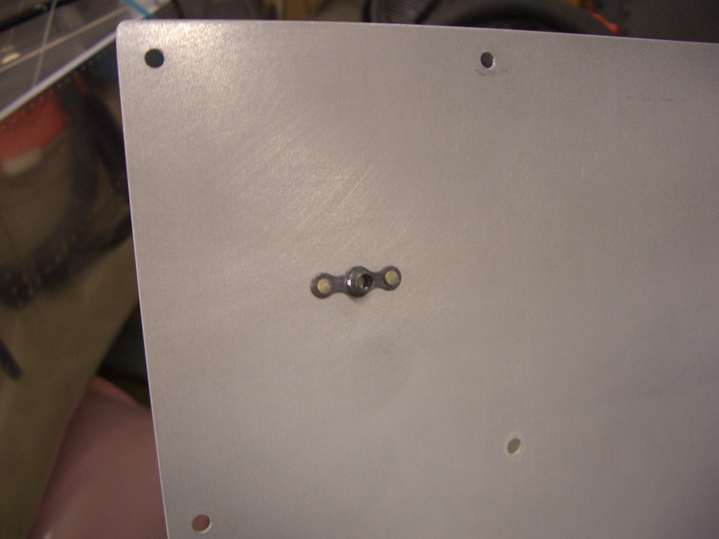
I then installed a nutplate on the underside of the seat pan.

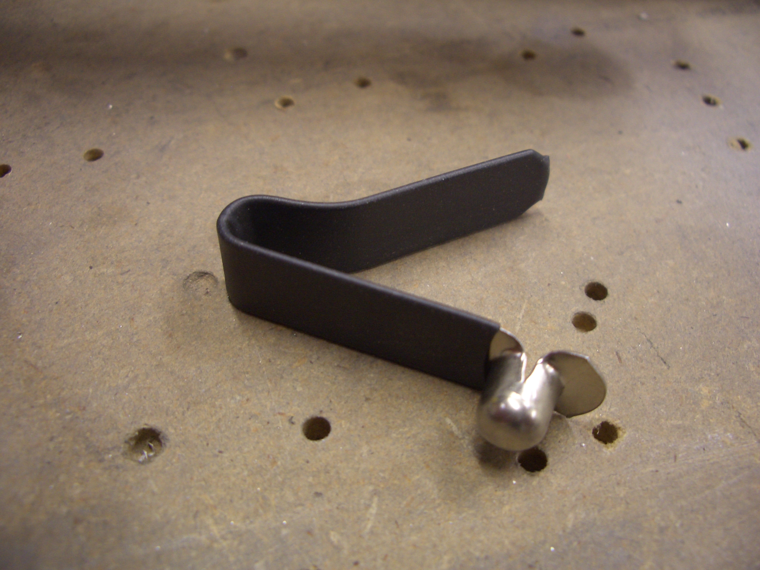
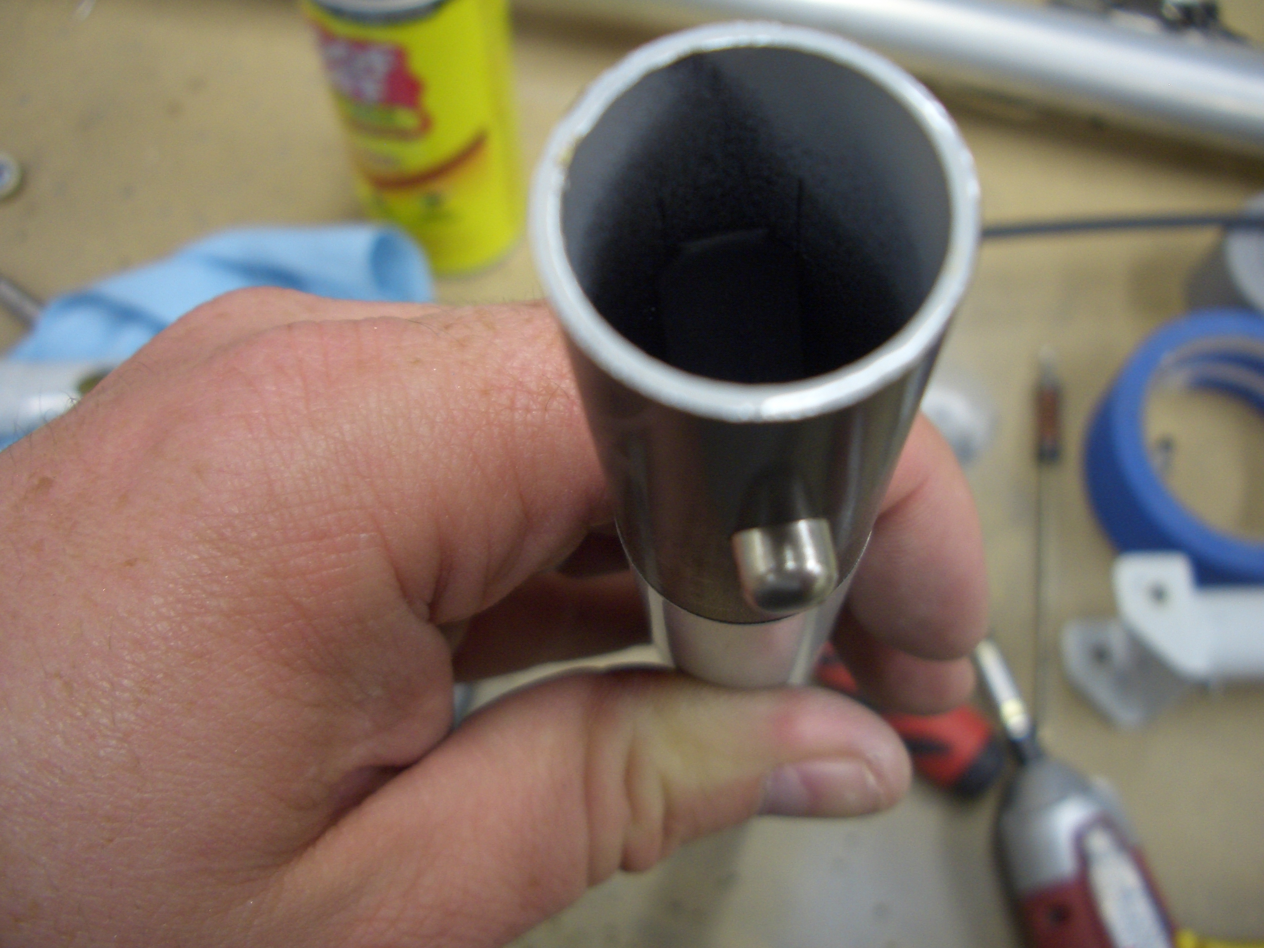
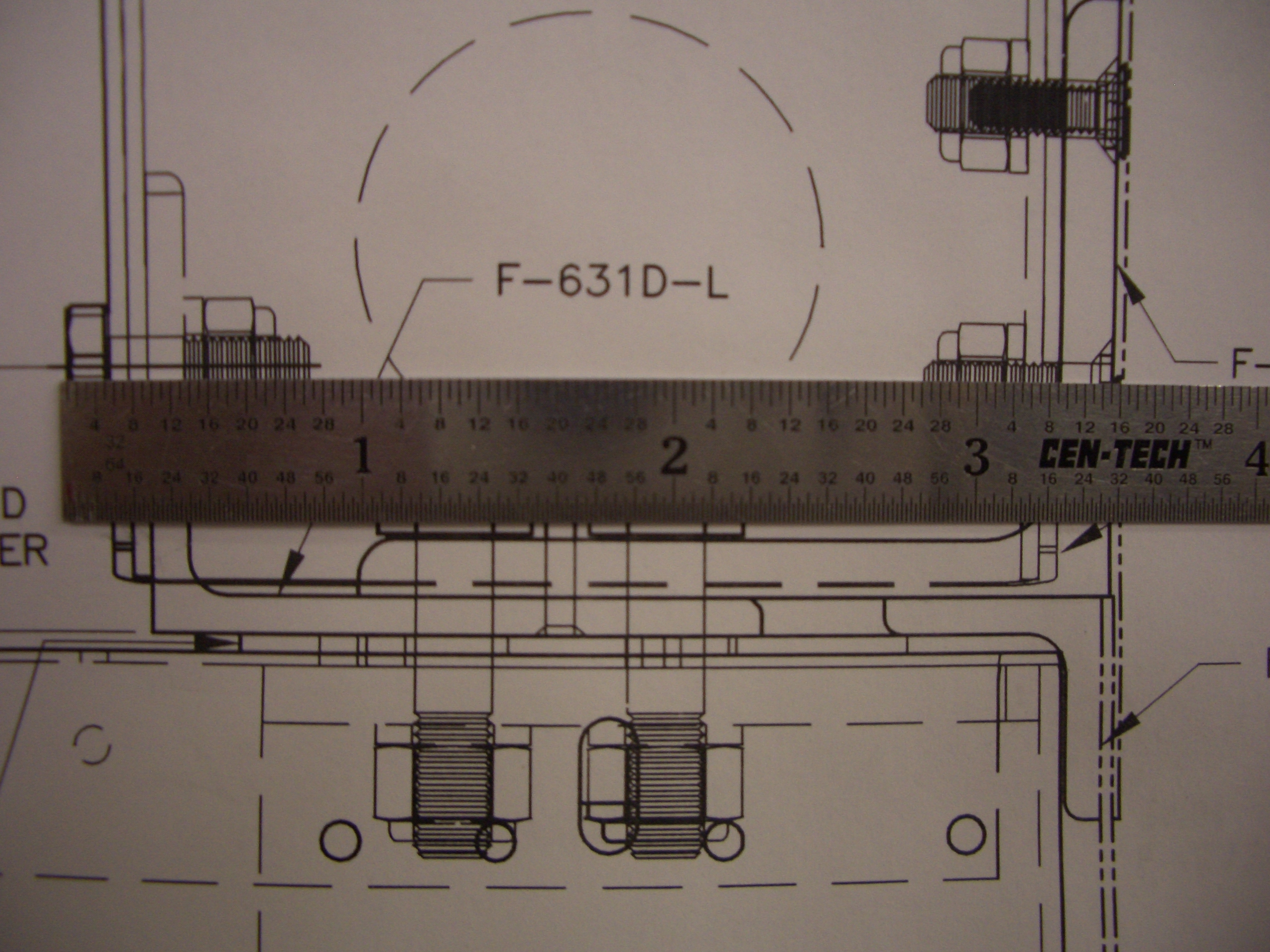
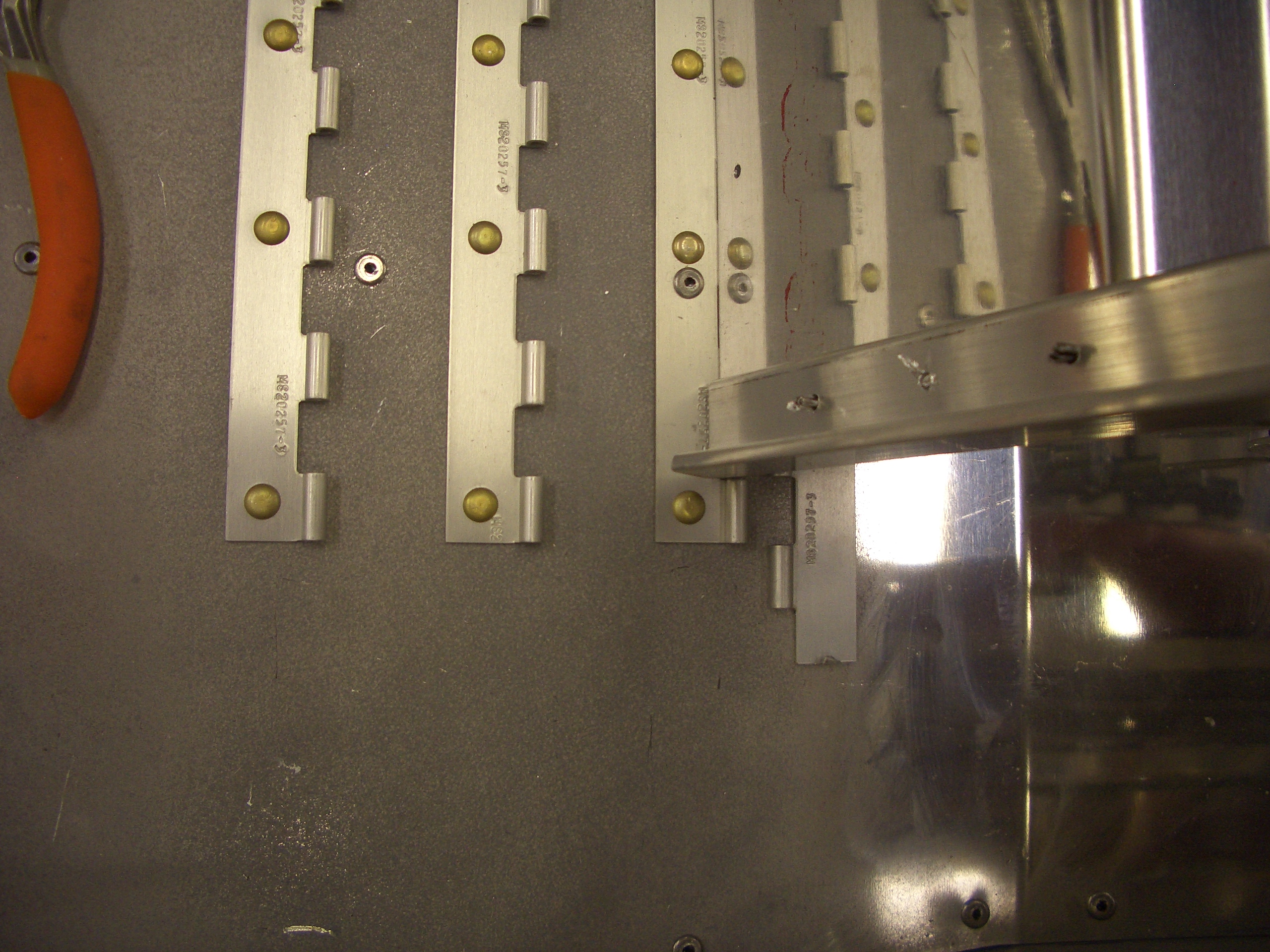
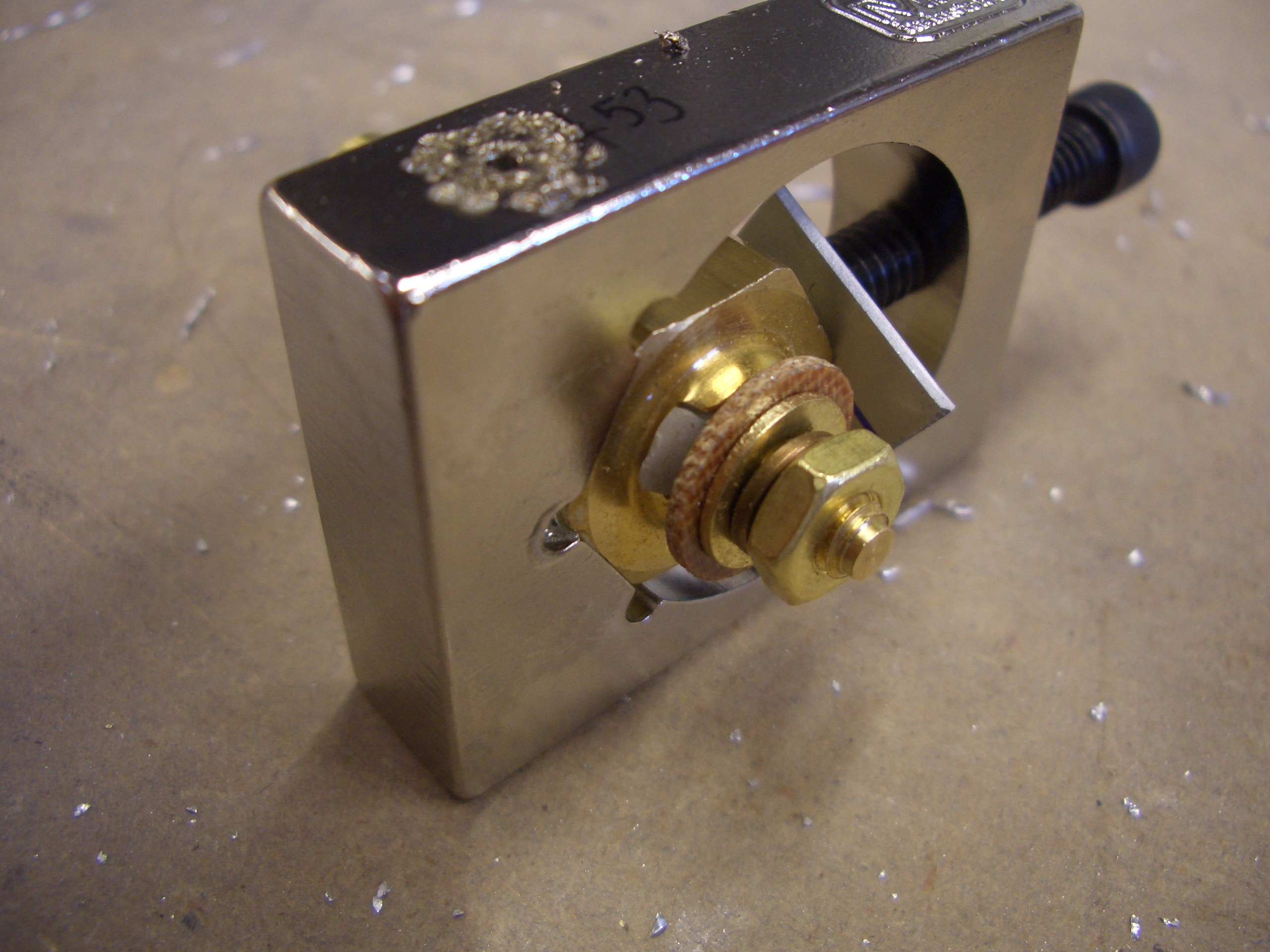
The copilot’s stick is removable so that it can be taken out when not needed.  The stick is a tight friction fit in the base, but Van’s recommends installing a bolt through the pair to keep the stick from inadvertently pulling out.  Apparently, this is due to an accident that happened a number of years ago when the copilot’s stick pulled out while somebody was trying to land the plane from the right seat.  The problem with this approach is that it means removing the copilot’s stick requires tools and would be inconvenient at best.  A number of builders recommended using a quick release locking mechanism.  I ordered a few of these clips from McMaster-Carr.  Since the copilot’s grip wiring is going to be running past this clip, I slipped on a piece of heat shrink tubing since the edges are pretty sharp.

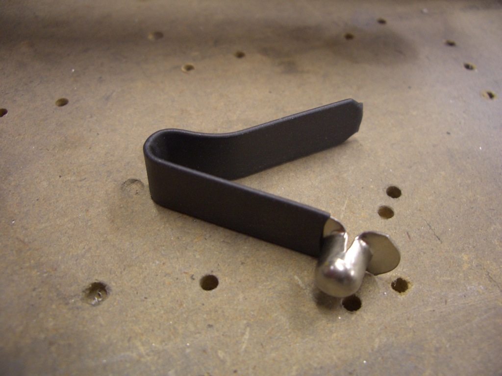
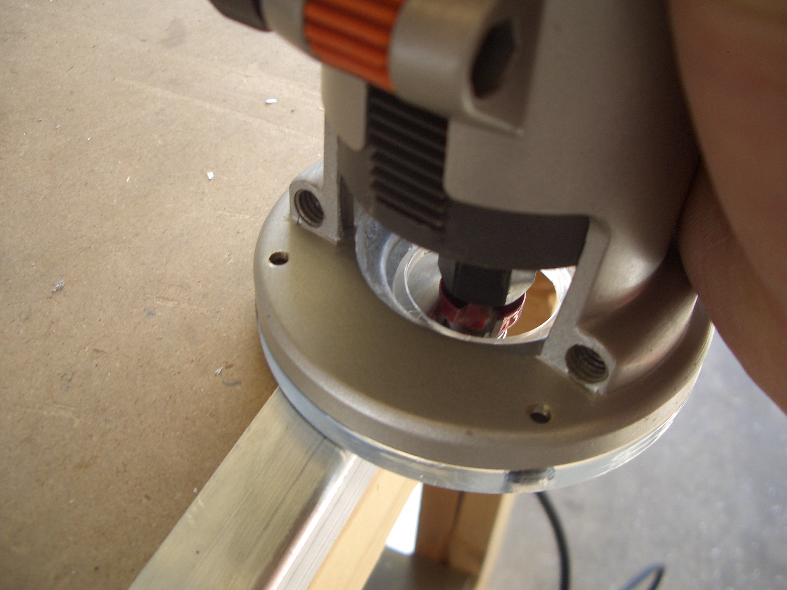
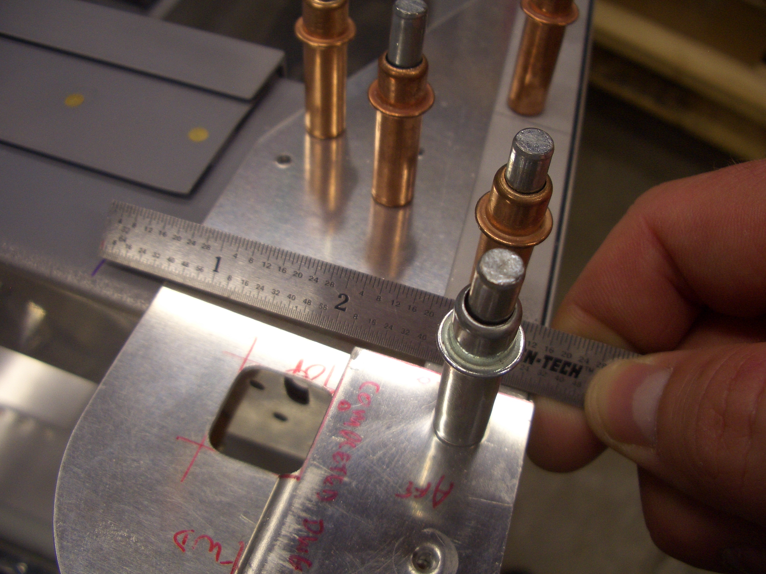
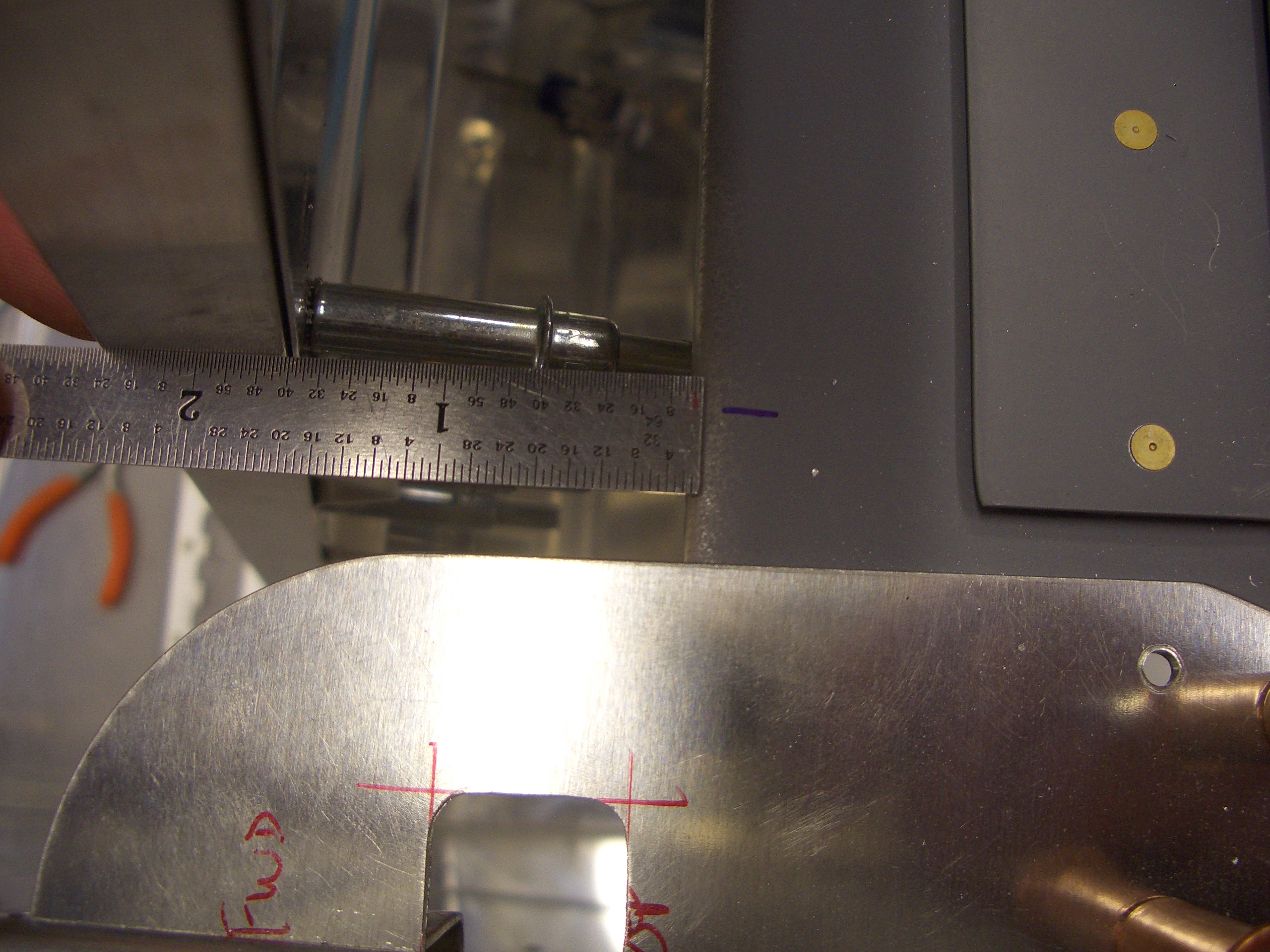
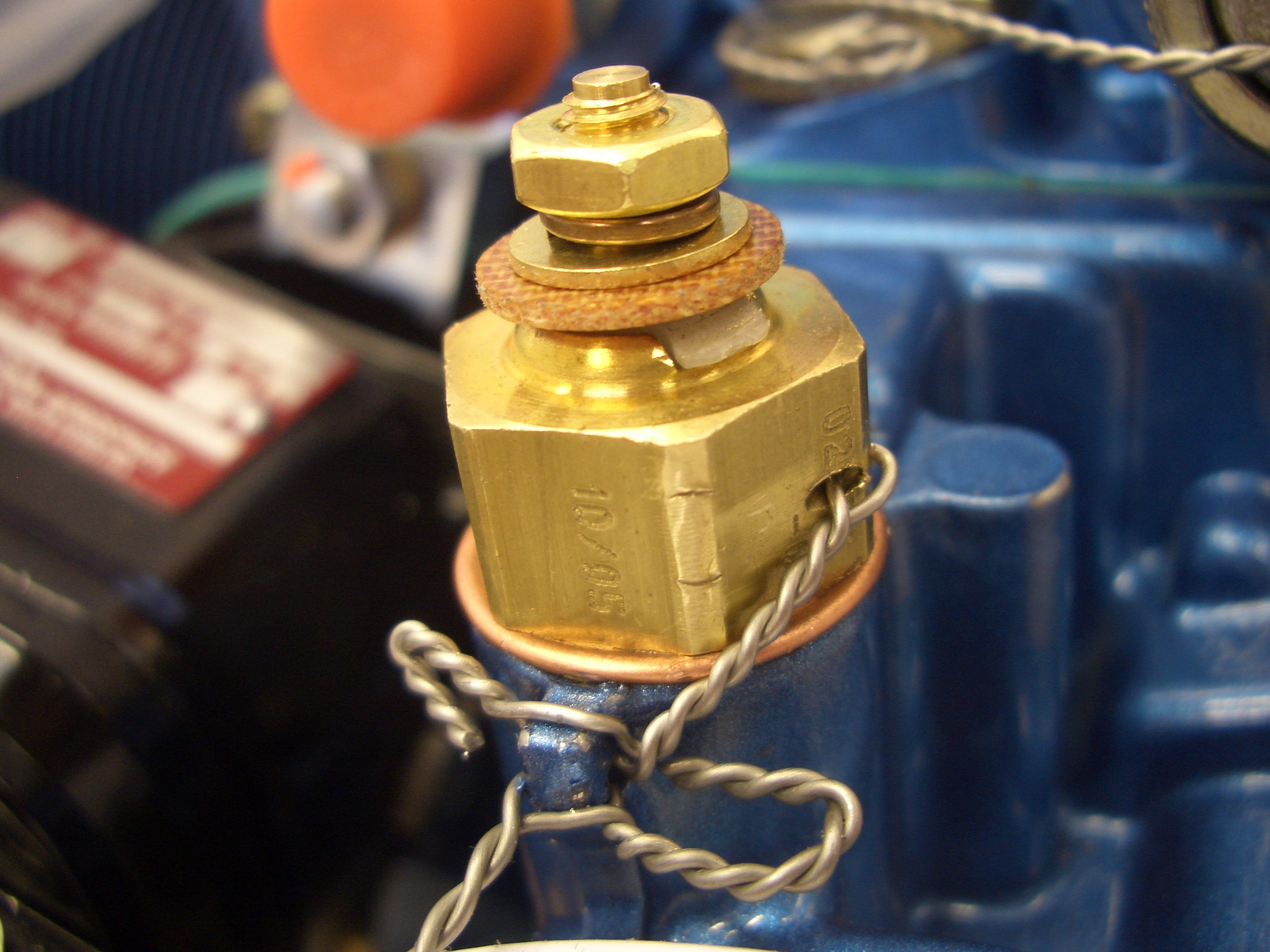
I drilled/reamed a 1/4″ hole through the stick and base, then installed the clip into the stick.

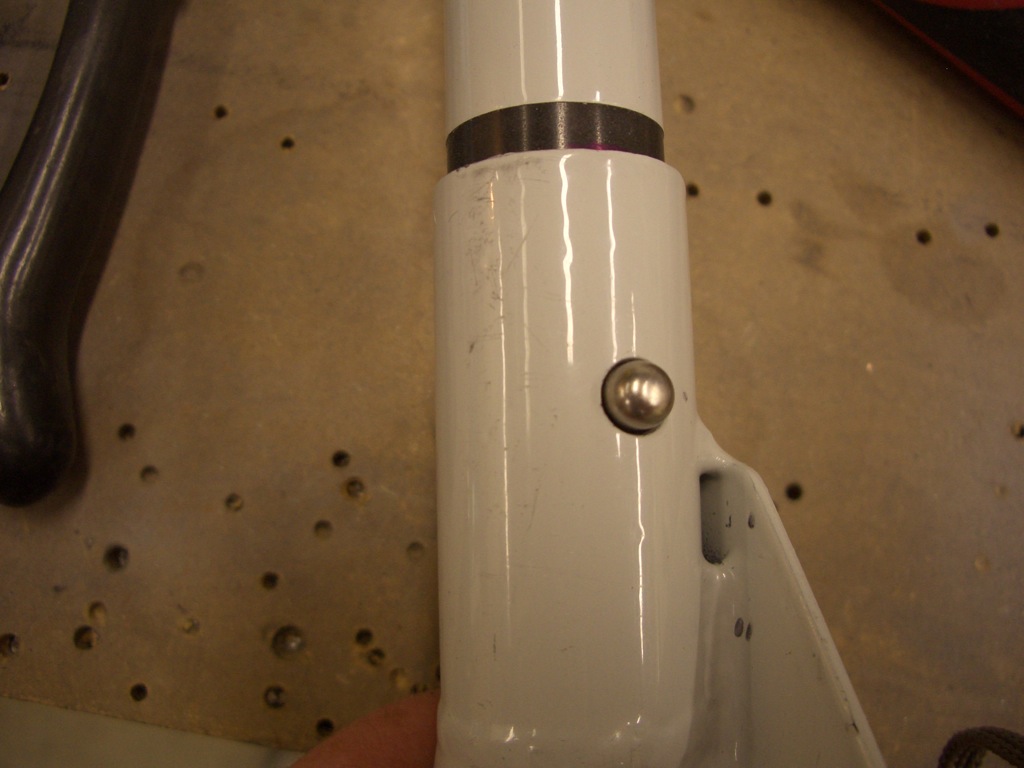
When the stick is inserted into the base, the clip locks the two together so that there is no way they can come apart inadvertently.  When I want to remove the stick, I just have to push in on the button and pop the stick out.  There will be a small 2 circuit Molex connector inside the stick for the copilot’s PTT switch that will need to be disconnected.

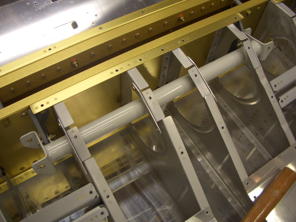
Finally, I reinstalled the control stick mount.  I need to fiddle with the washers a little bit to make this pivot smoothly.

Engine Accessories and Controls

I did some reading today in the manuals that came with the engine to determine where various sensors are installed.  This is the spot for the oil temperature sensor (which is included with the Dynon probe kit).  Fortunately, Aero Sport included the crush washer under the orange cap that was in this spot.  I haven’t torqued this down yet because I’ve been unable to find a torque value for this fitting.

I also took off the cover plate for the prop governor mounting pad.  I put a thin coat of grease on the gasket and installed it on the pad.

Finally, I installed the PCU 5000 X governor on the pad.  I haven’t torqued these either since the cable mounting bracket will have to attach using a couple of these bolts.  It looks like there will barely be enough threads showing without that, so I’ll have to ask about whether I can just back these studs out a couple of turns or not.

I also took the cover off of the back of the magneto and installed the wire harness.  These use T20 screws, and I wouldn’t have had enough room to get my torx driver between here and the firewall if I had waited until the engine was hung.

I also shaved a few thousandths off a couple of AN960-10 washers to allow this center control piece to pivot freely.  The bearings used in the control mounts are very sensitive to side loading.  Even 5-10 thousandths of an inch difference between the mount spacing and the spacing in the control piece was enough to make moving this have some noticeable friction.  It’s completely frictionless now.

Started Seat Backs

My buddy Andre stopped by and we started working on the seat backs.  Andre started fabricating the various angles while I got started modifying the upper seat adjustment mechanism.  I laid out and cut lightening holes according to the plans.  I have no idea why they didn’t lay these out evenly along the length.

The ends need a couple of tapering cuts so that they look cooler.

I laid out all the holes along the four sides according to the holes and them drilled them through both seat backs simultaneously.  I only drilled these to #40 right now.  Once everything is drilled, I’ll step these up to #30.

Two of the 0.063″ angles need the corners rounded over.  I used my trim router and a 1/8″ roundover bit to radius the corner.

After cleaning this up on the scotchbrite wheel, you can see how it tucks nicely into the bend at the top of the seat back.

Finally, we match drilled the side and top angles to one of the seat backs.

Worked on Seat Backs

I’ve heard that most if not all builders have a problem with the seat backs interfering with the roll bar.  I took a measurement off the plans, and the rollbar is 3.5″ from the outer skin to the horizontal bolt on the inboard edge.

I measured 3.5″ in from the skin along the front edge of the seat back support and made a mark.

With the outboard edges of the seat backs positioned flush with the end of the seat pan hinges…

…the top of the seat back extends past the mark by just over 1/4″

If I move the seats over by one eyelet…

…then the top of the seat backs are inside the roll bar by a little less than 1/4″.  Building the seat backs according to plans, but swapping the left and right seats will result in this inset.

I cut the lower hinge for the left seat and match drilled it and the lower angle to the seat back.

Here’s a closeup of the lower end of the angle showing the notch that is cut to make room for the hinge.

With the left seat back installed on the right side of the plane, I was surprised to see that the seat back was perfectly in line with the cutout for the controls.  If the seats were installed according to plans, not only would they interfere with the roll bar, the stick would not be centered between your legs.

Work on Seats, Engine Accessories

I drilled the upper seat back adjustment to the right seat back.

Here is the seat installed temporarily.  I still need to drill out everything to #30, but all of the fabrication is done.

Here is the upper seat back adjustment showing how the flange fits into the notches on the cross member.  Afterward, I knocked out all of the left seat except for the upper adjustment mechanism.

I found out that the new prop governor cable mounting bracket doesn’t attach to these mounting bolts, so I torqued these down and lacquer sealed them.

I also swapped the oil pressure fitting and the plug so that I have more clearance from the engine mount.  This required removing the upper hold down clip from the right mag cover plate so that I could get a wrench on this fitting.

I also installed the fuel overflow fitting.  A rubber tube will be installed here to route any fuel overflow away from the hot exhaust.

Update: This is the sniffle valve and shouldn’t be installed here.  I searched all over the engine and couldn’t find any other fittings that this could screw in to, but the engine was mounted on the palette at the time and I couldn’t see where this should actually mount.  See this entry for where this should actually be mounted.

Seats, Oil Temperature Sensor

I finished fabricating the seat backs.  I still need to drill all the holes out to #30, but at least all of the fabrication is done.  My son just had to try it out.

I had to increase the angle of the bend for the upper seat adjustment mechanism so that it would slip into either of the slots in the upper seat support.  Here you can see the two different adjustment positions.  The seats can also be leaned all the way back so that the seats simply rest against the upper seat support.

I was not comfortable that the Dynon oil temperature sensor had no provision for safety wiring it to prevent it from backing out.  I purchased this tool to drill a hole in the sensor.  The sensor fits inside and is clamped in place with the black bolt on the right.  I drill is then run through the small hole on the top (the one surrounded by metal chips).

Here is the oil temp sensor fully torqued down and safety wired

Prepped Seats for Riveting, Canopy Seal Supports

My buddy Andre stopped by today and we drilled all of the seat back rivets out to #30 and then deburred all of the seat components.  We also deburred the forward ribs.

I got started fabricating the outboard canopy seal supports.  These require laying out for rivet holes and cutting notches so that these can be curved to follow the curve of the forward edge of the canopy.

Canopy Seal Support Angles

I finished fabricating and drilling the outboard canopy seal support angles.  These will support pieces of weatherstripping that the front edge of the canopy will close down against.

Here you can see that the seal support angle sits 1/8″ below the flange of the subpanel.  This provides a gap for the weatherstipping.

Worked on Forward Fuselage and Canopy Decks

Because I’m going with the Dynon SkyView system, the aft end of the forward fuselage ribs need to be cut off.  I will move these over a bit and mount them between the SkyView screens and the radio stack.

I deburred and dimpled the holes in the firewall that attach these ribs using my pop rivet dimple dies.

Finally, I deburred and dimpled the forward canopy decks and countersunk the longerons.

The forward and aft canopy decks are tied together using rivets in these two holes.