Finished F-757 Plate and Most of Tailcone Rivets

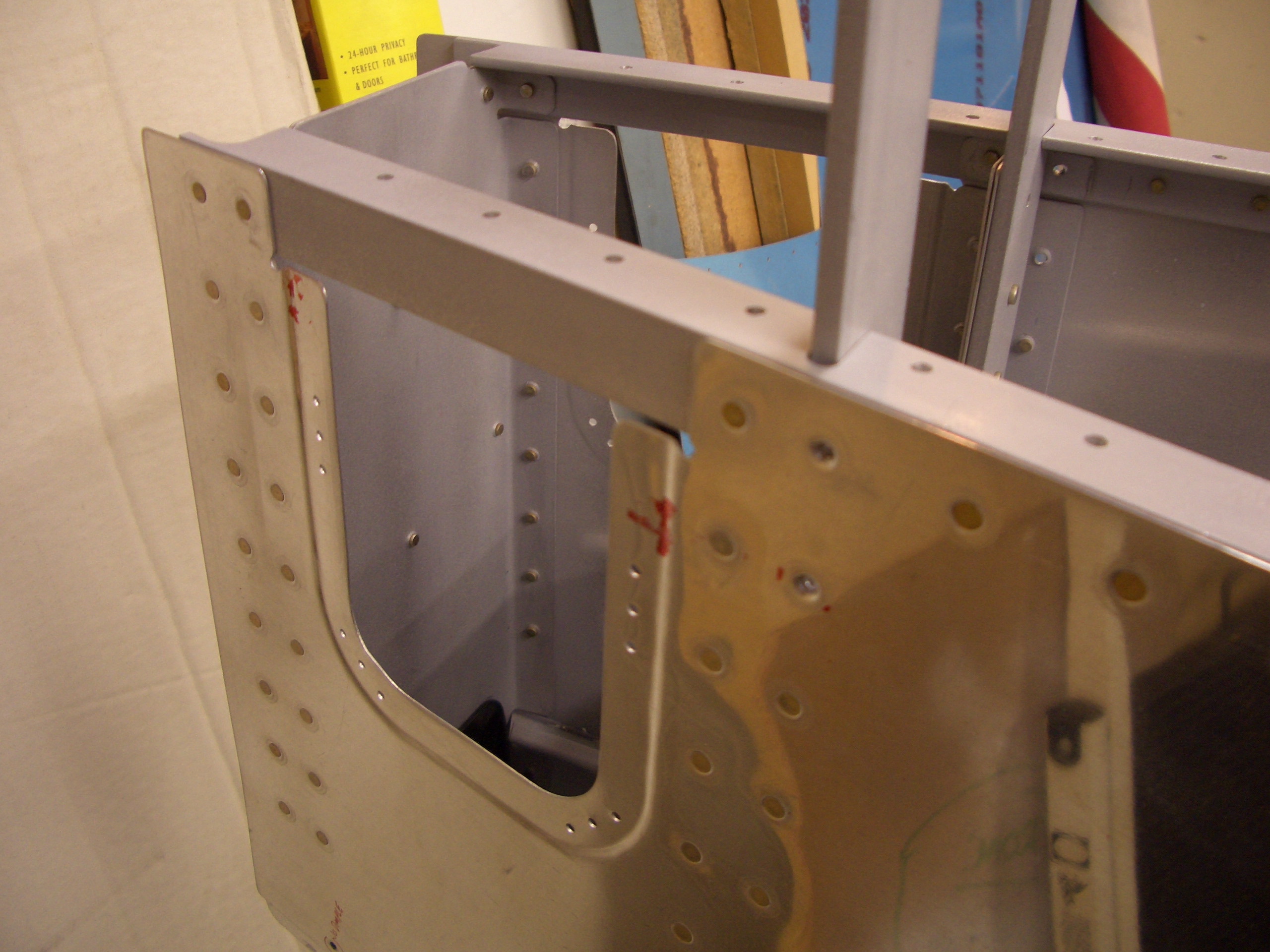
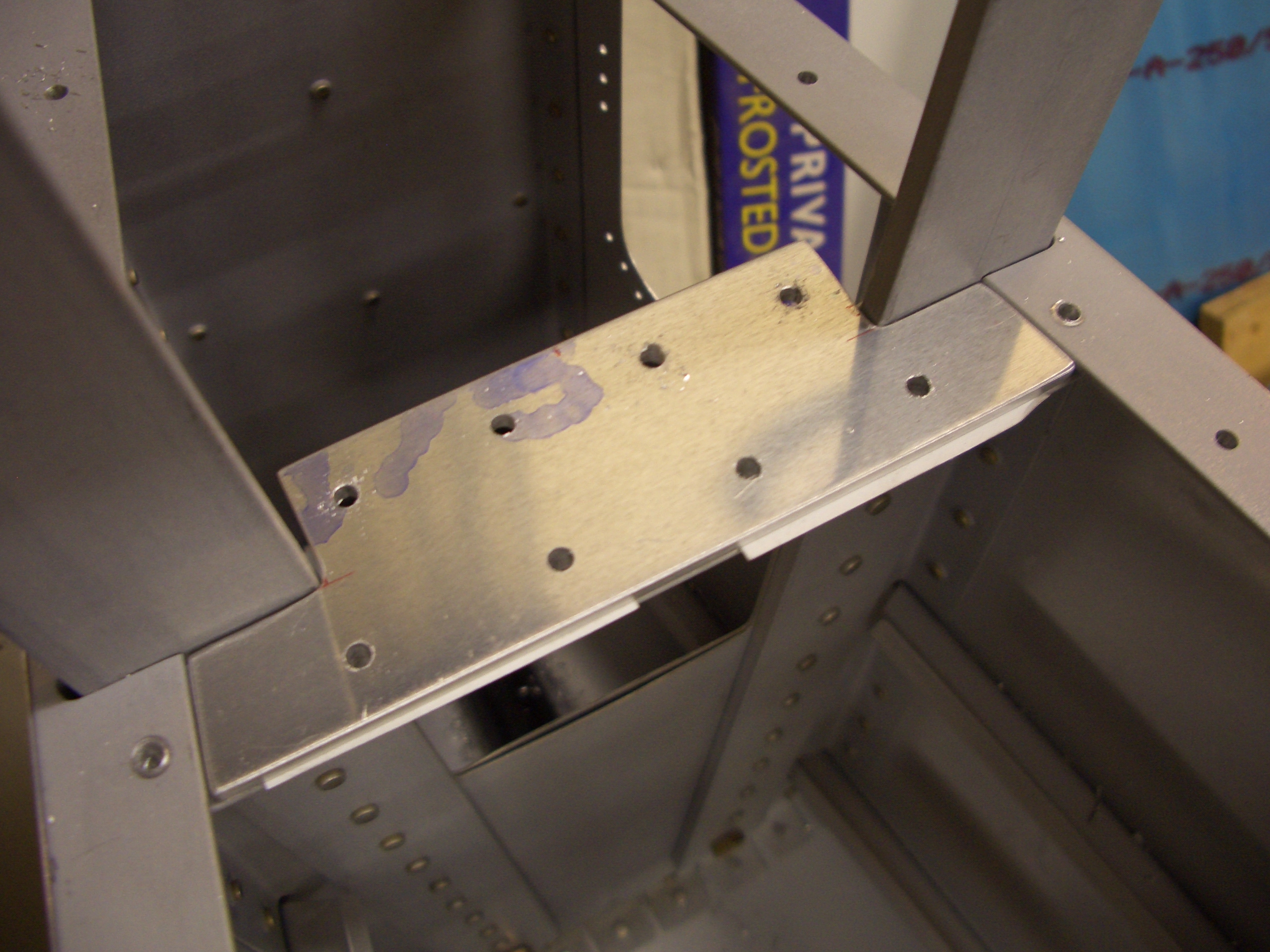
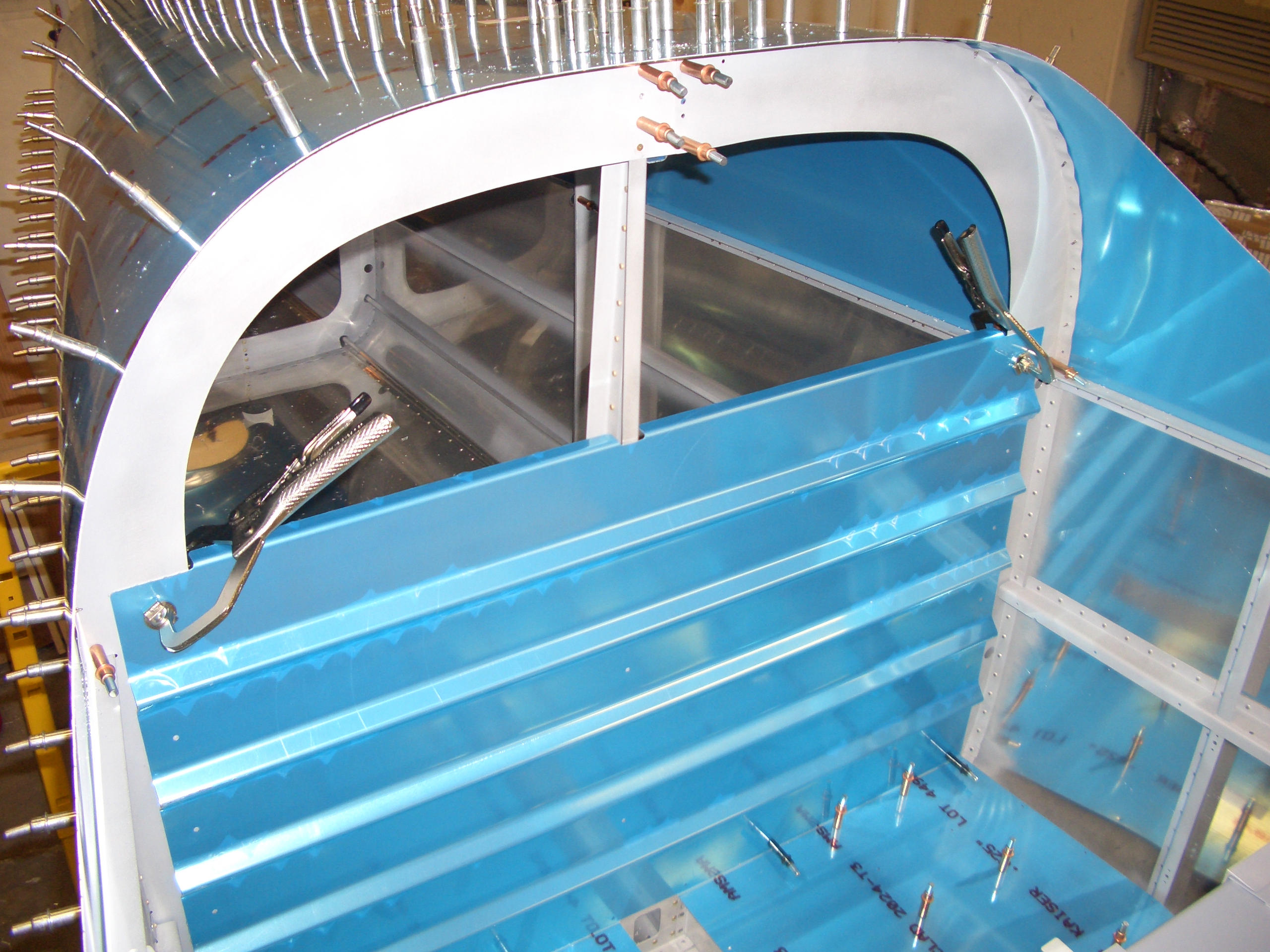
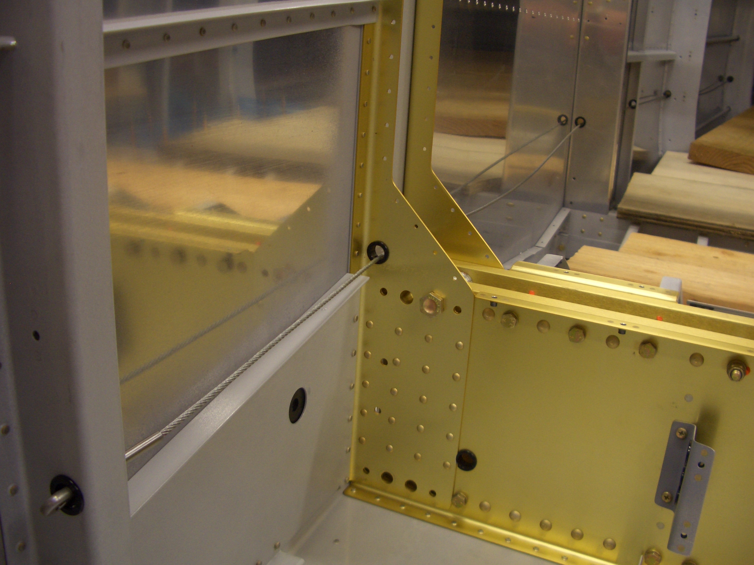
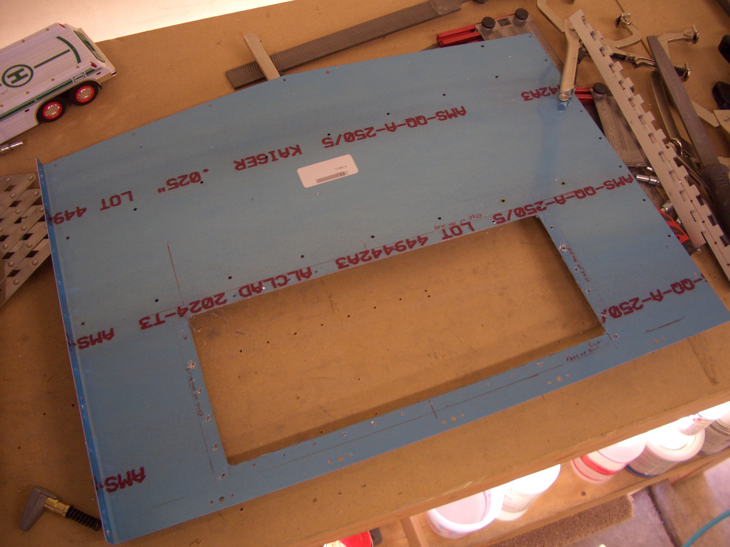
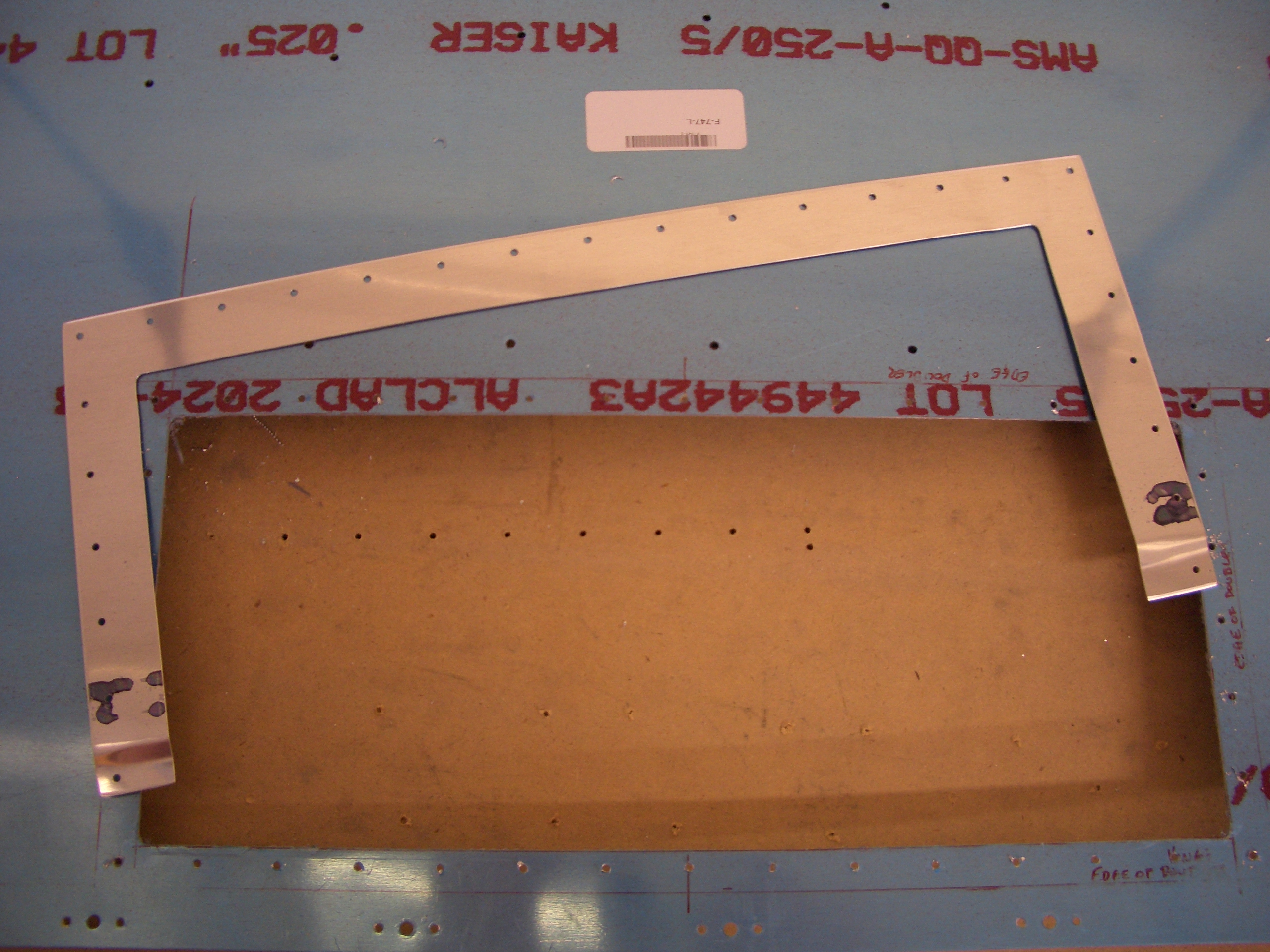
I finished the left F-757 plate and drilled it to the F-705 channel and longeron.

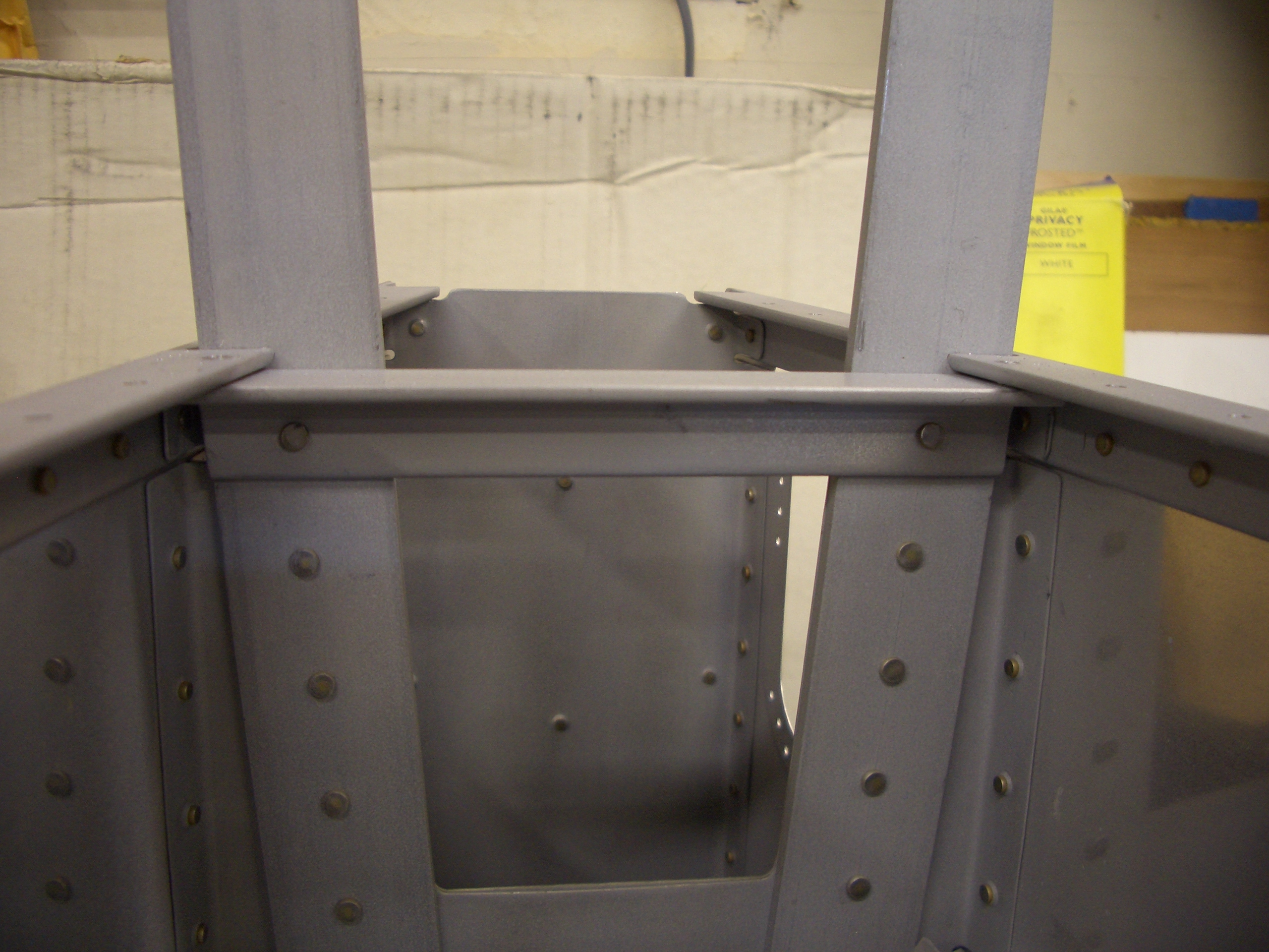
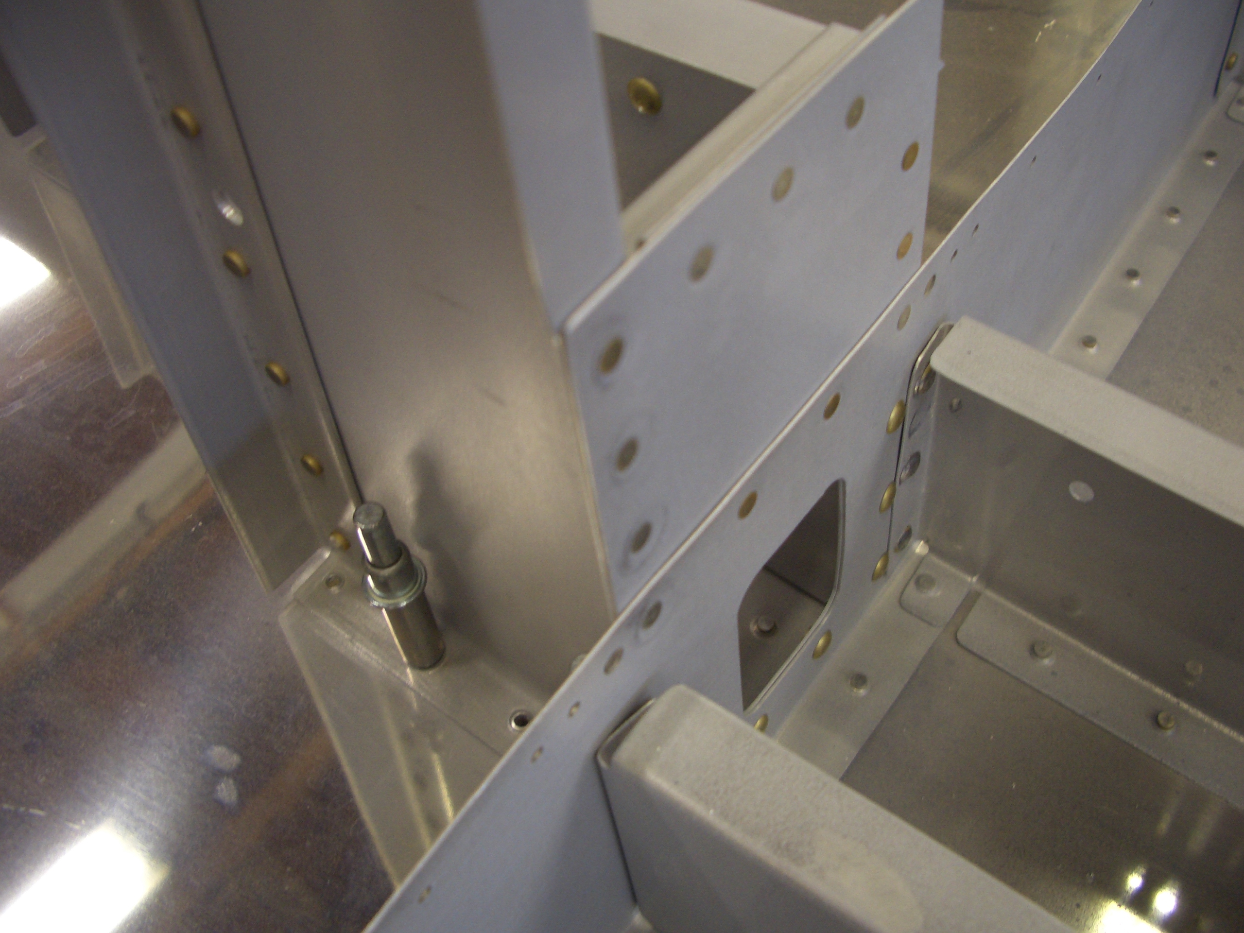
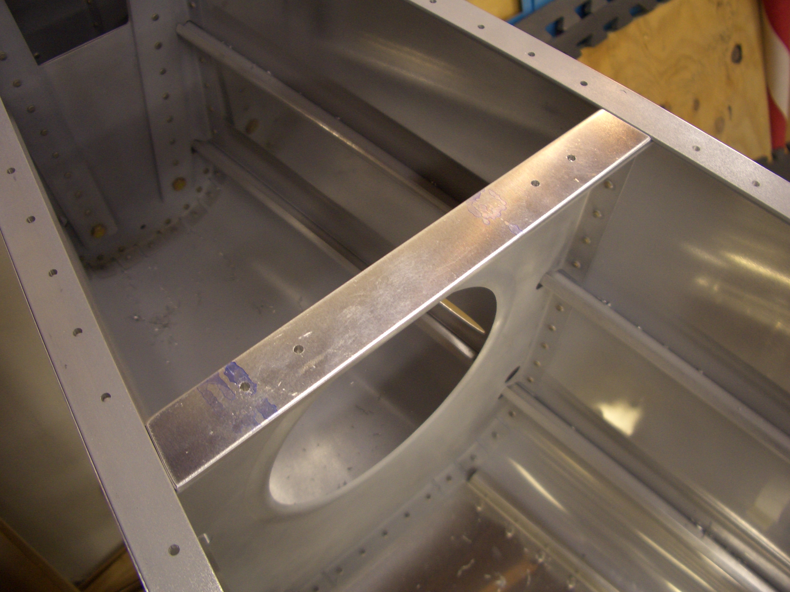
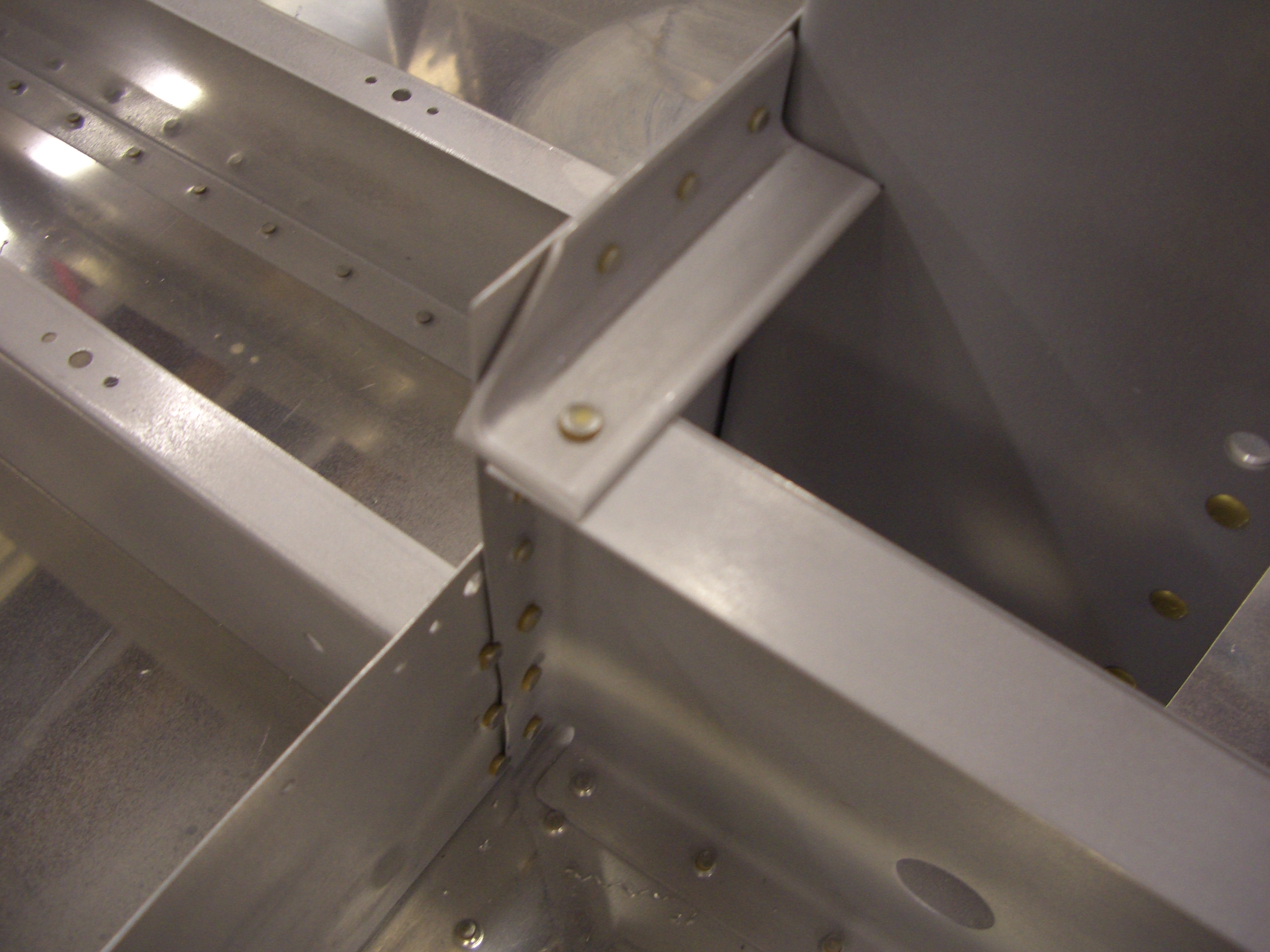
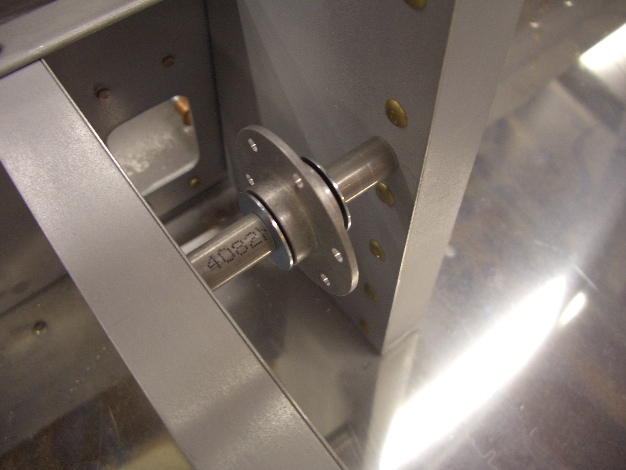
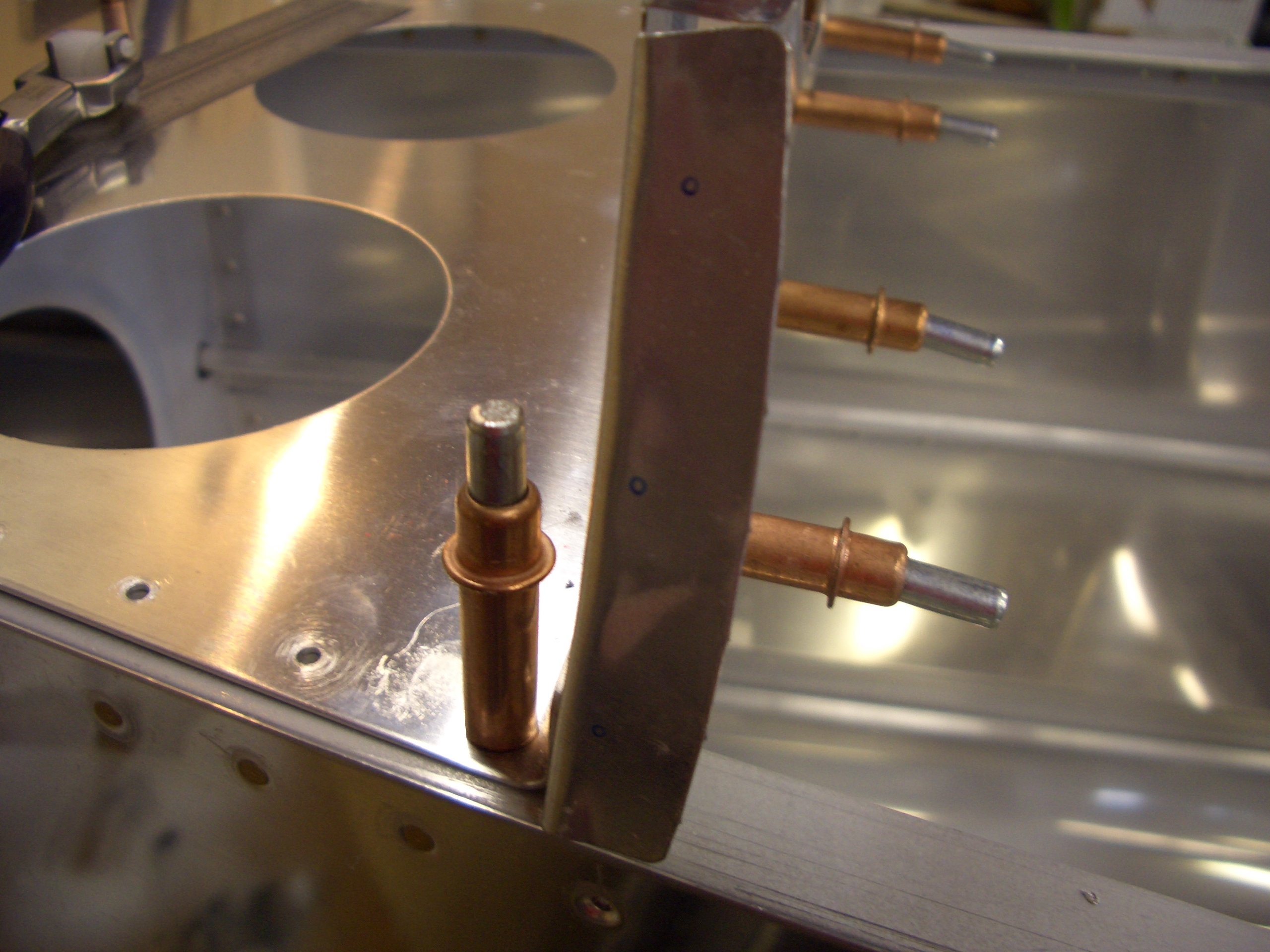
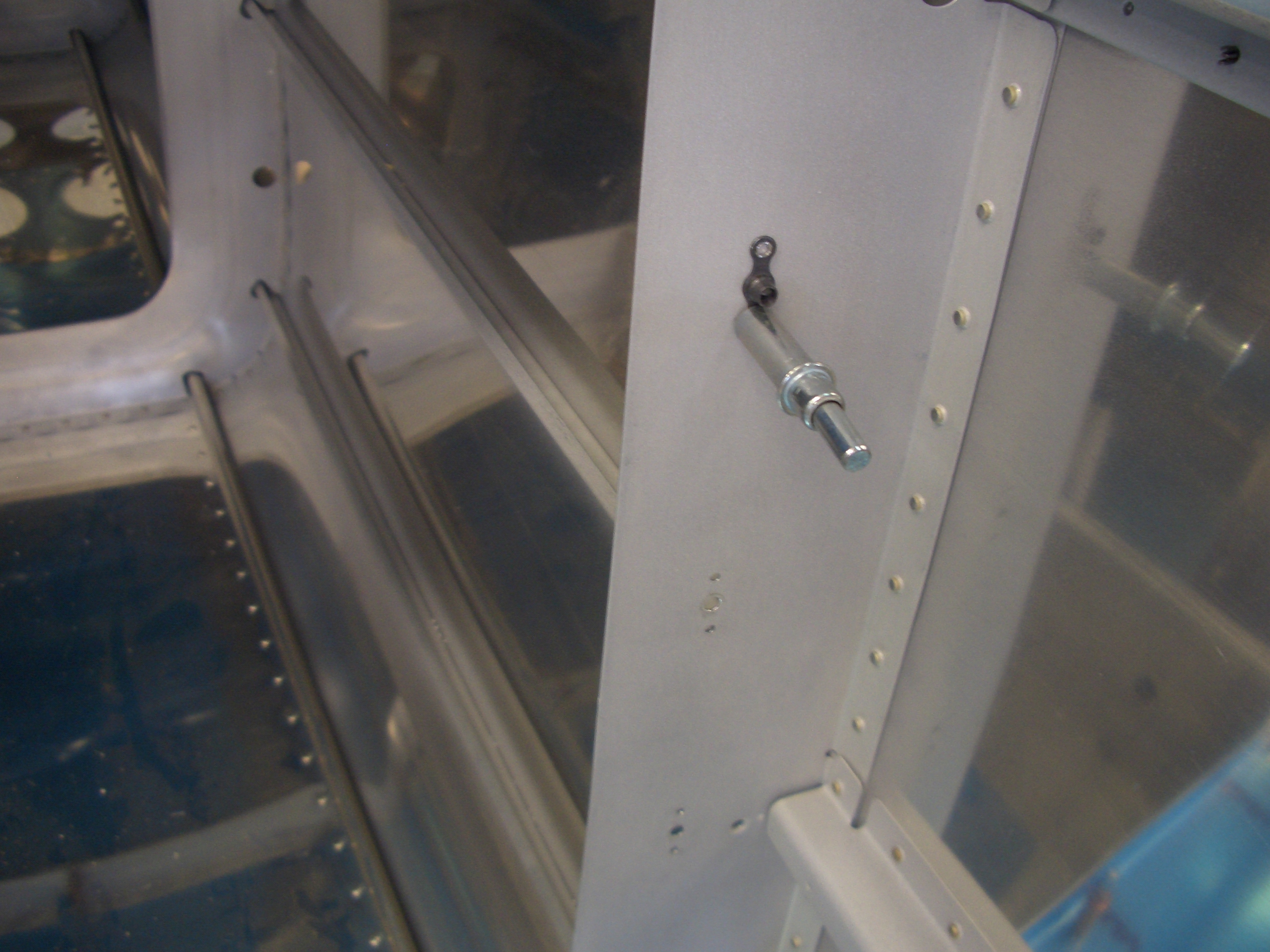
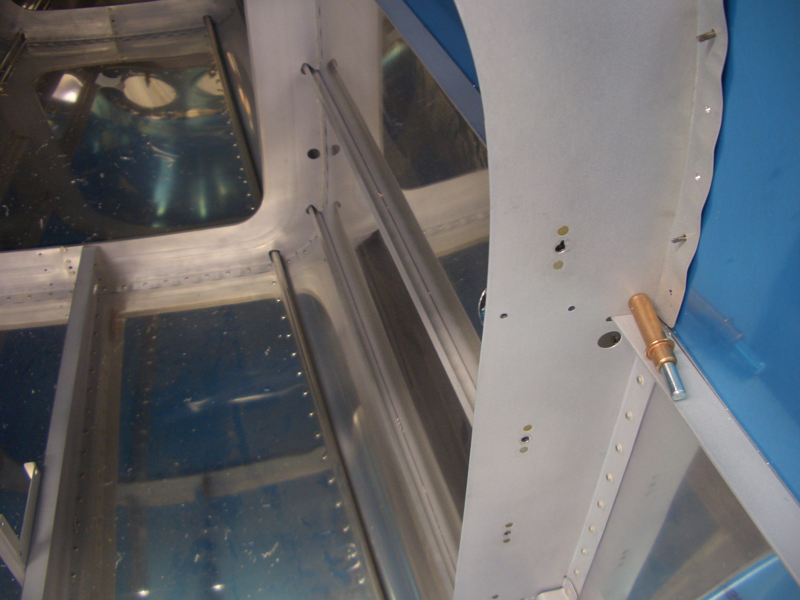
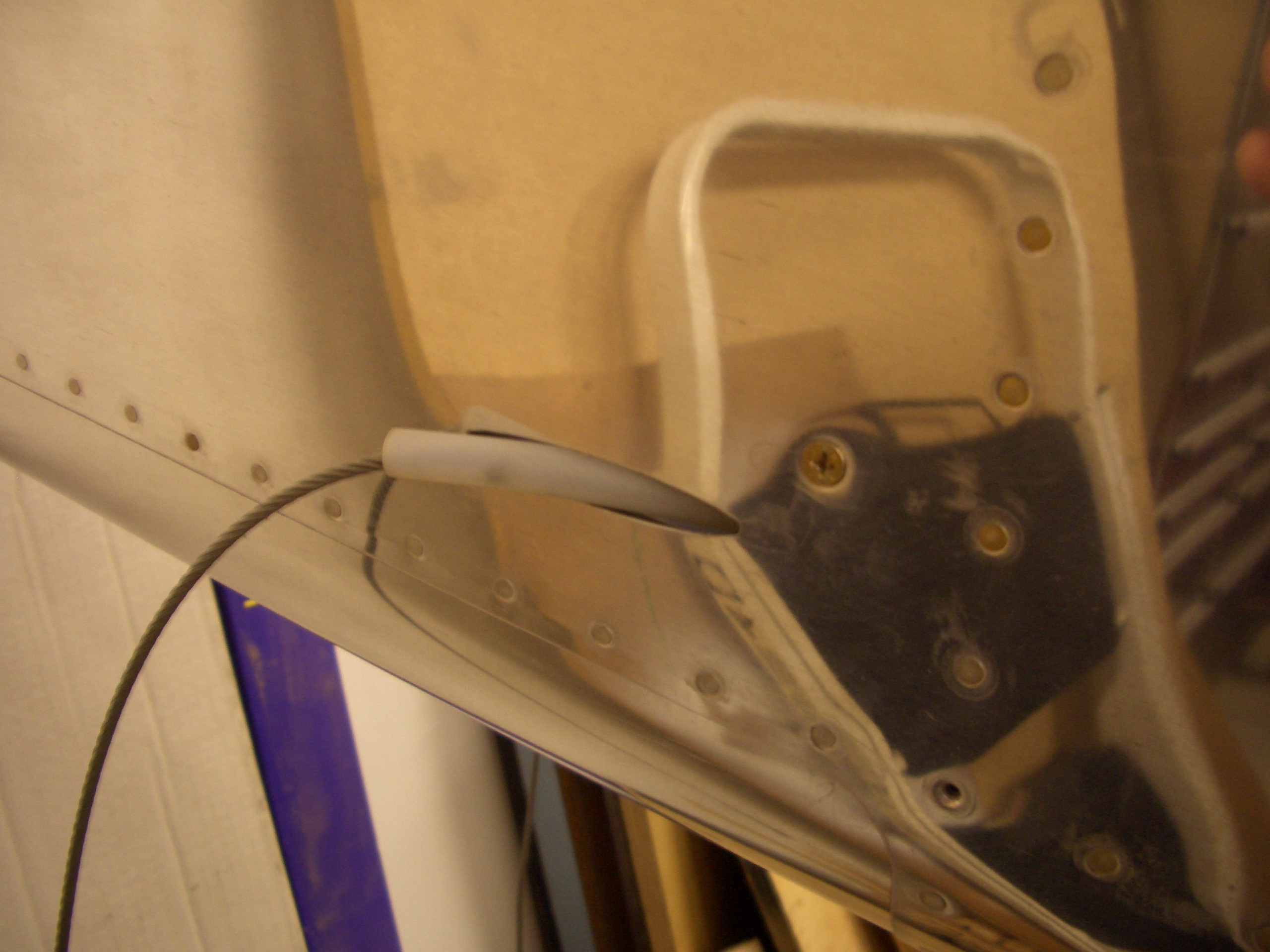
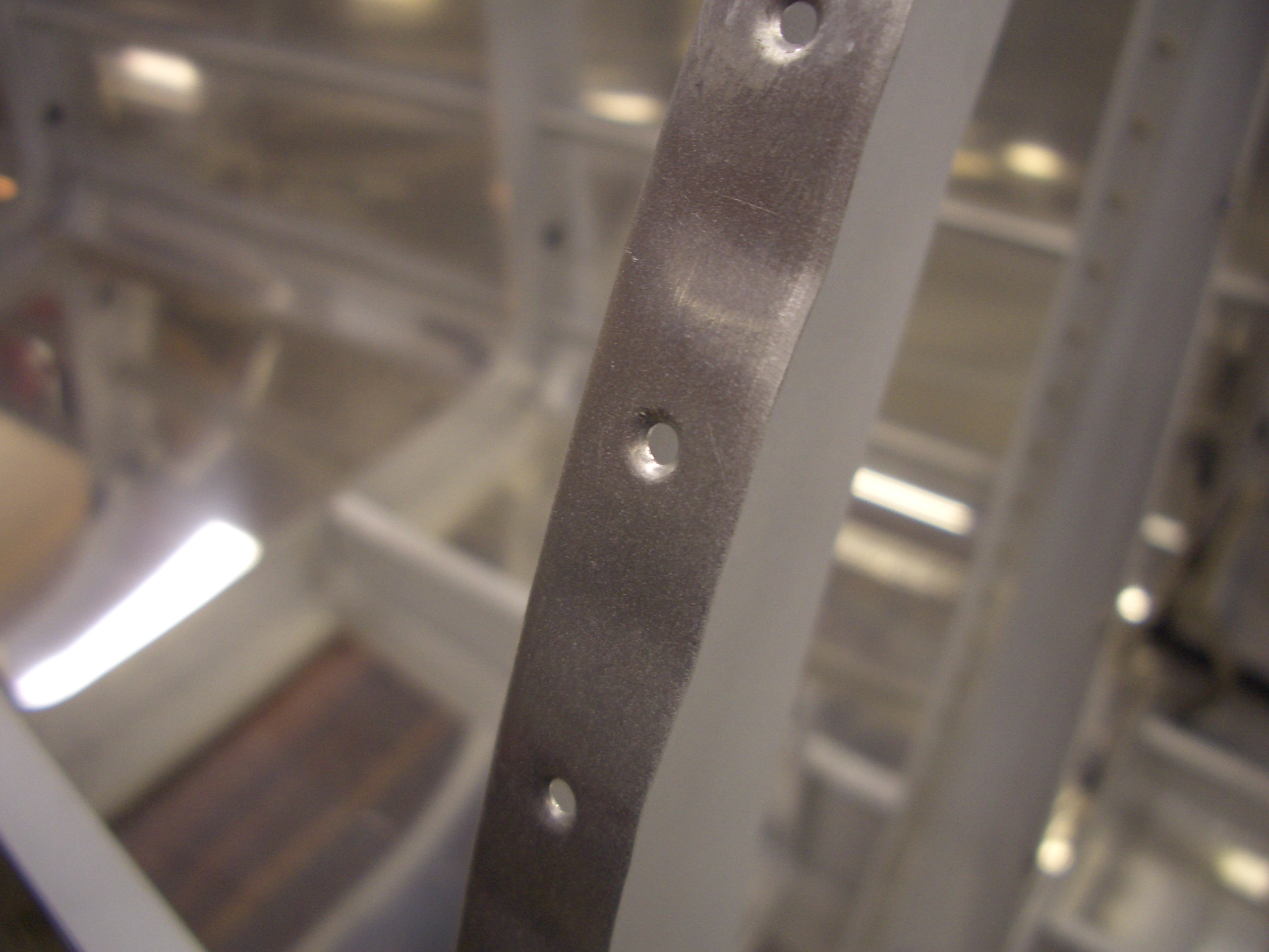
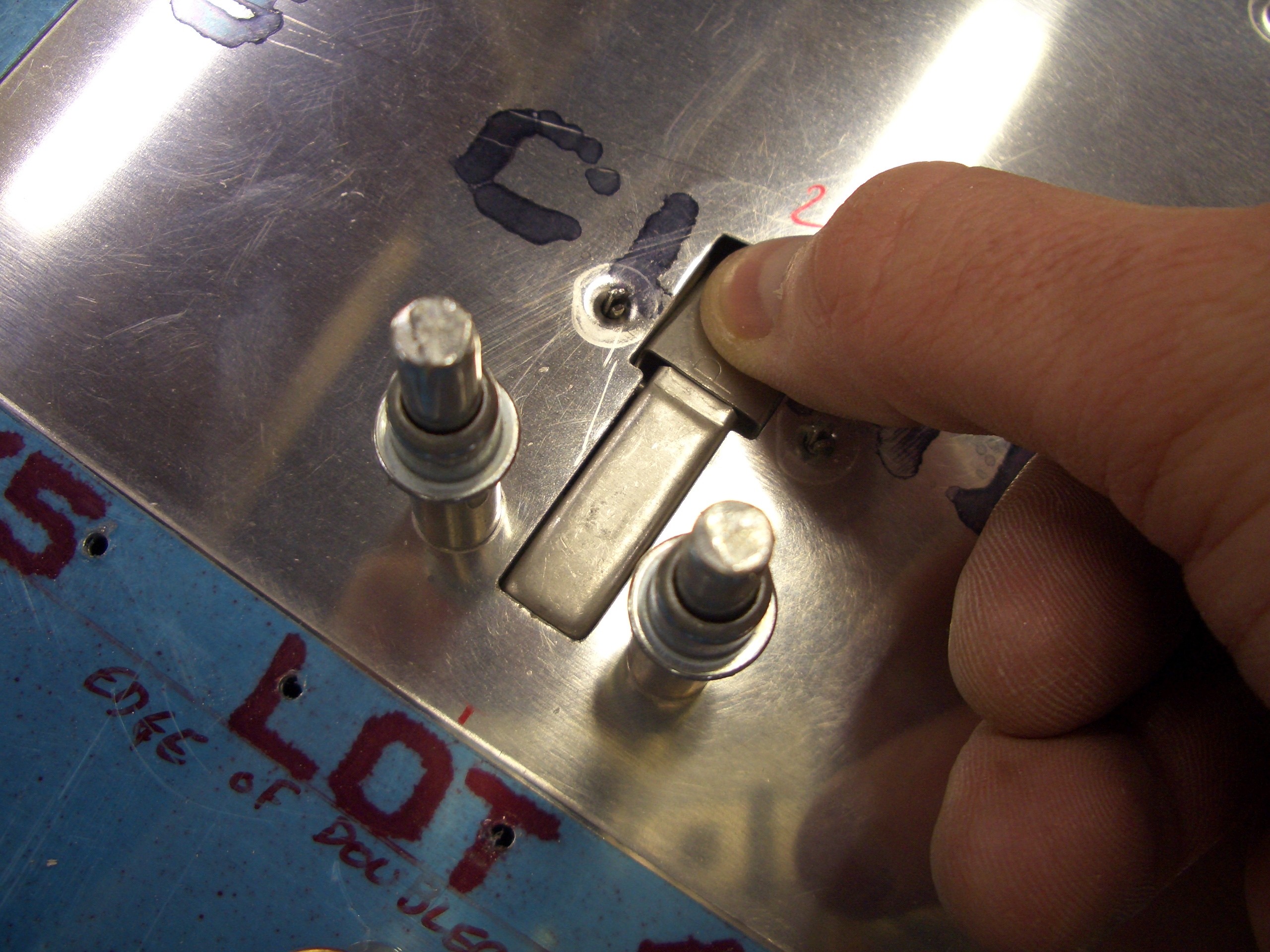
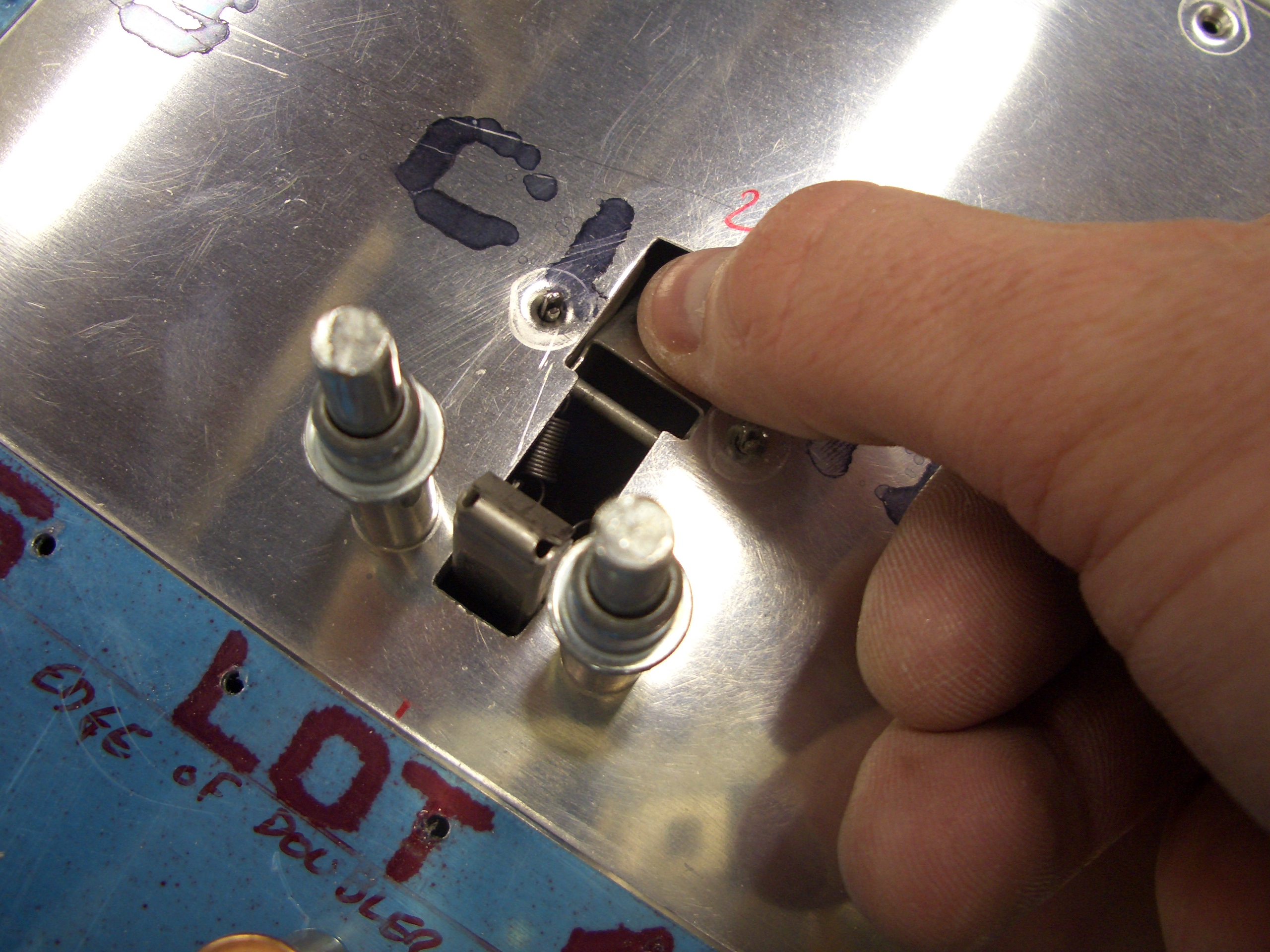
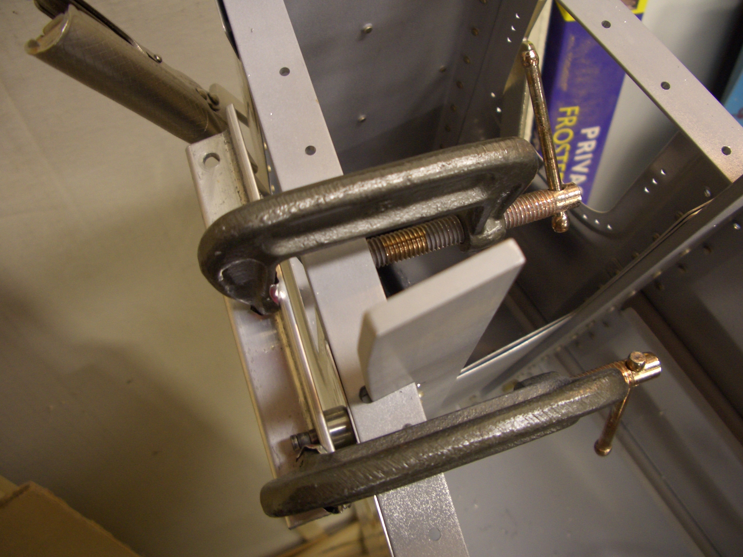
There were two holes in the aft fuselage that I couldn’t dimple earlier because I inadvertently riveted too far up F-711.  The vertical bars prevent getting a squeezer aligned with these holes, so I needed to get creative.  Since the longeron is already dimpled and thick enough not to flex, I could just use the male portion of the die to form the dimple.  Since the vertical bars prevent clamping directly, I used a scrap piece of angle and some clamps to either side to drive the male dimple die flush with the skin.  This worked perfectly, and a rivet sits completely flush in the hole.

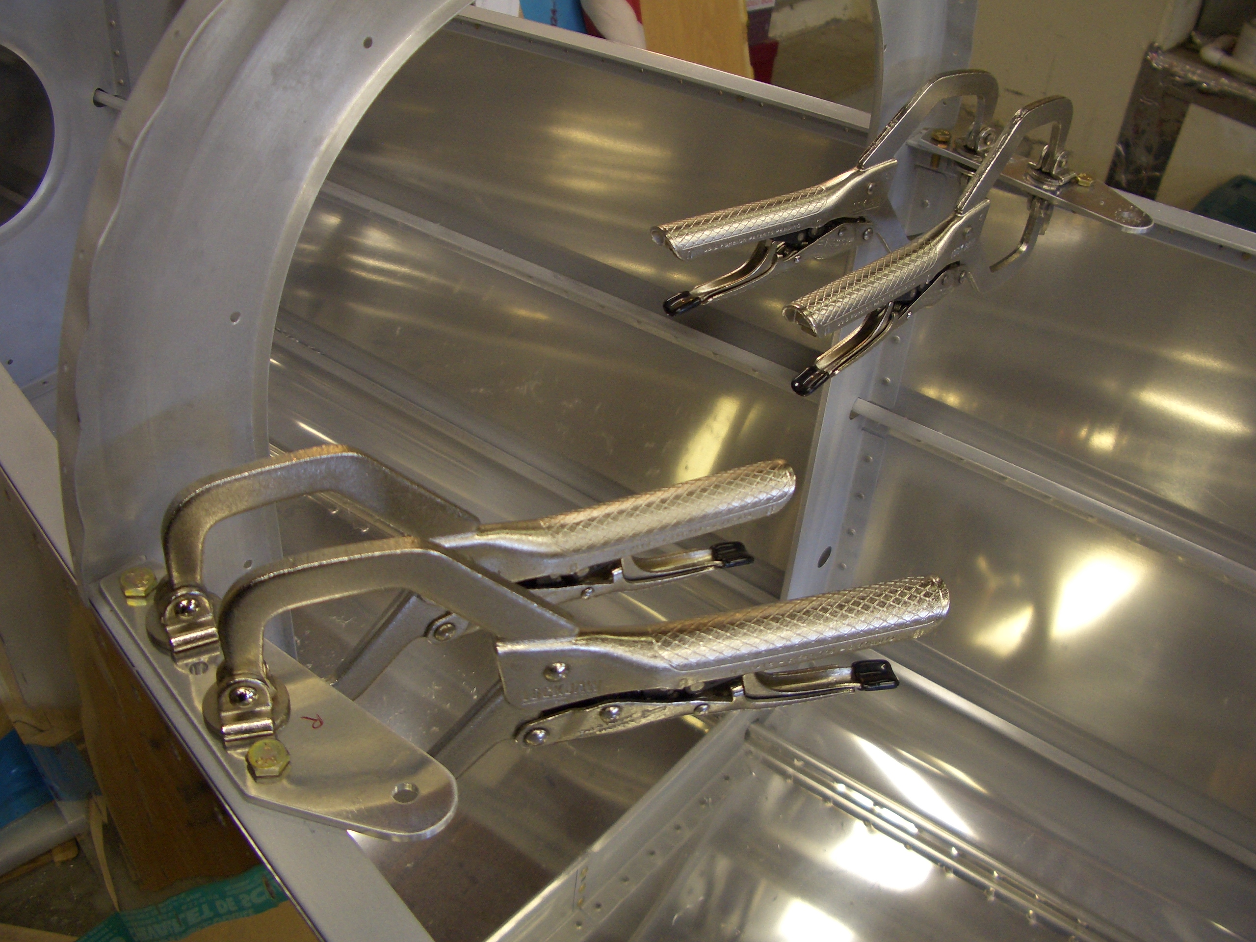
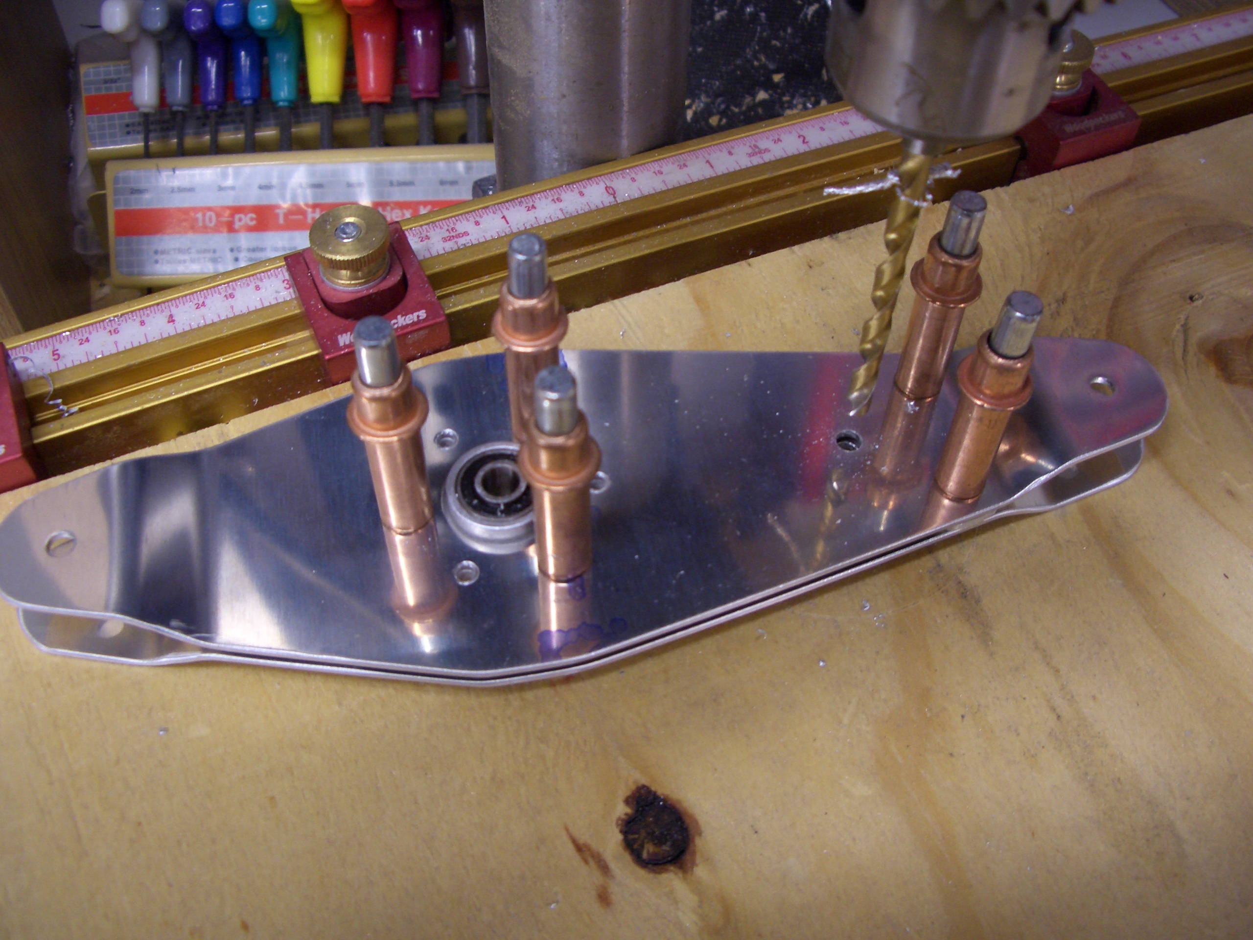
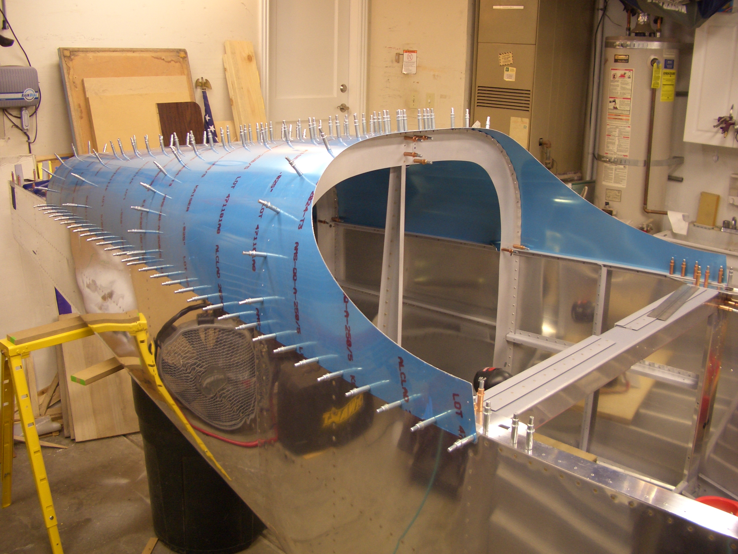
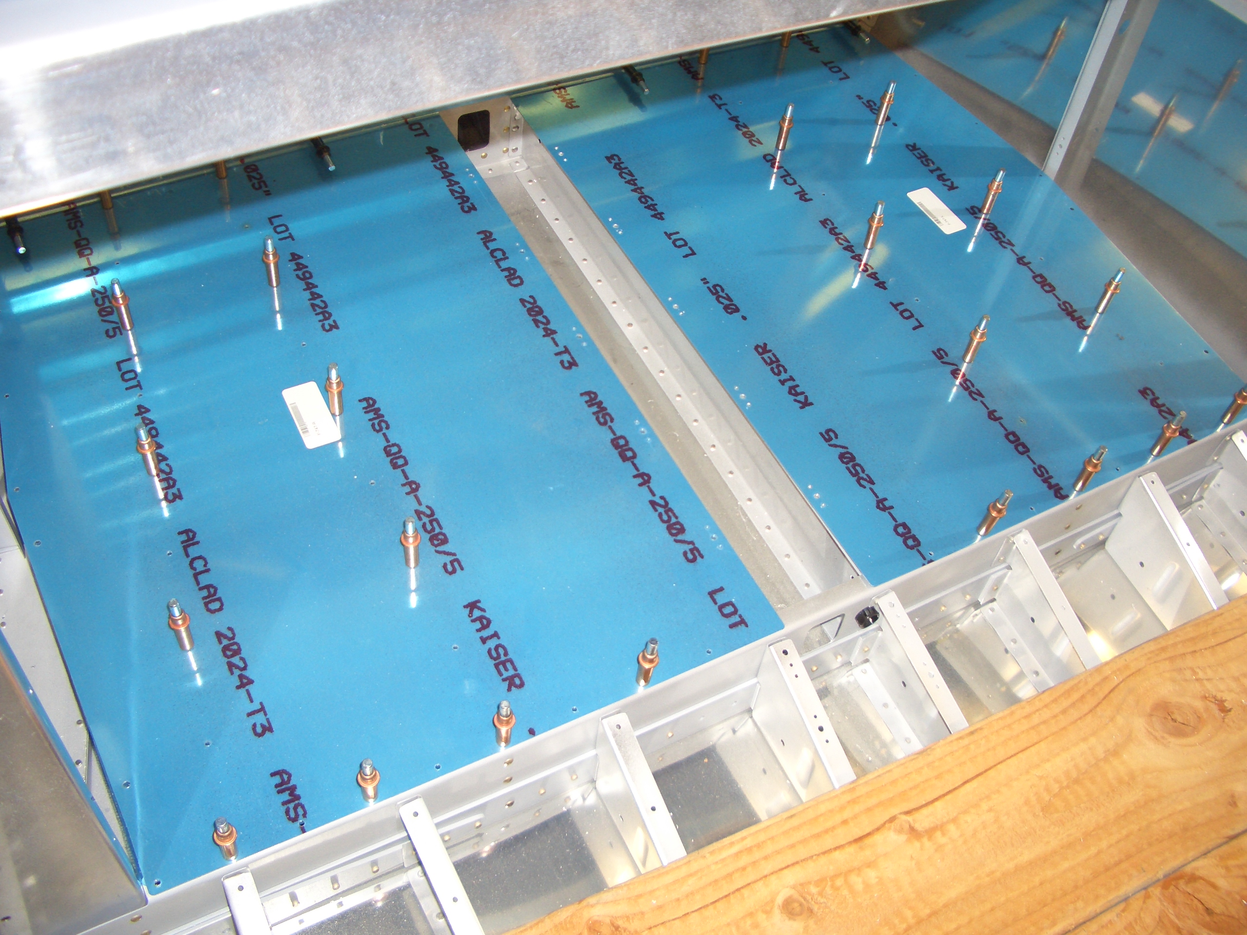
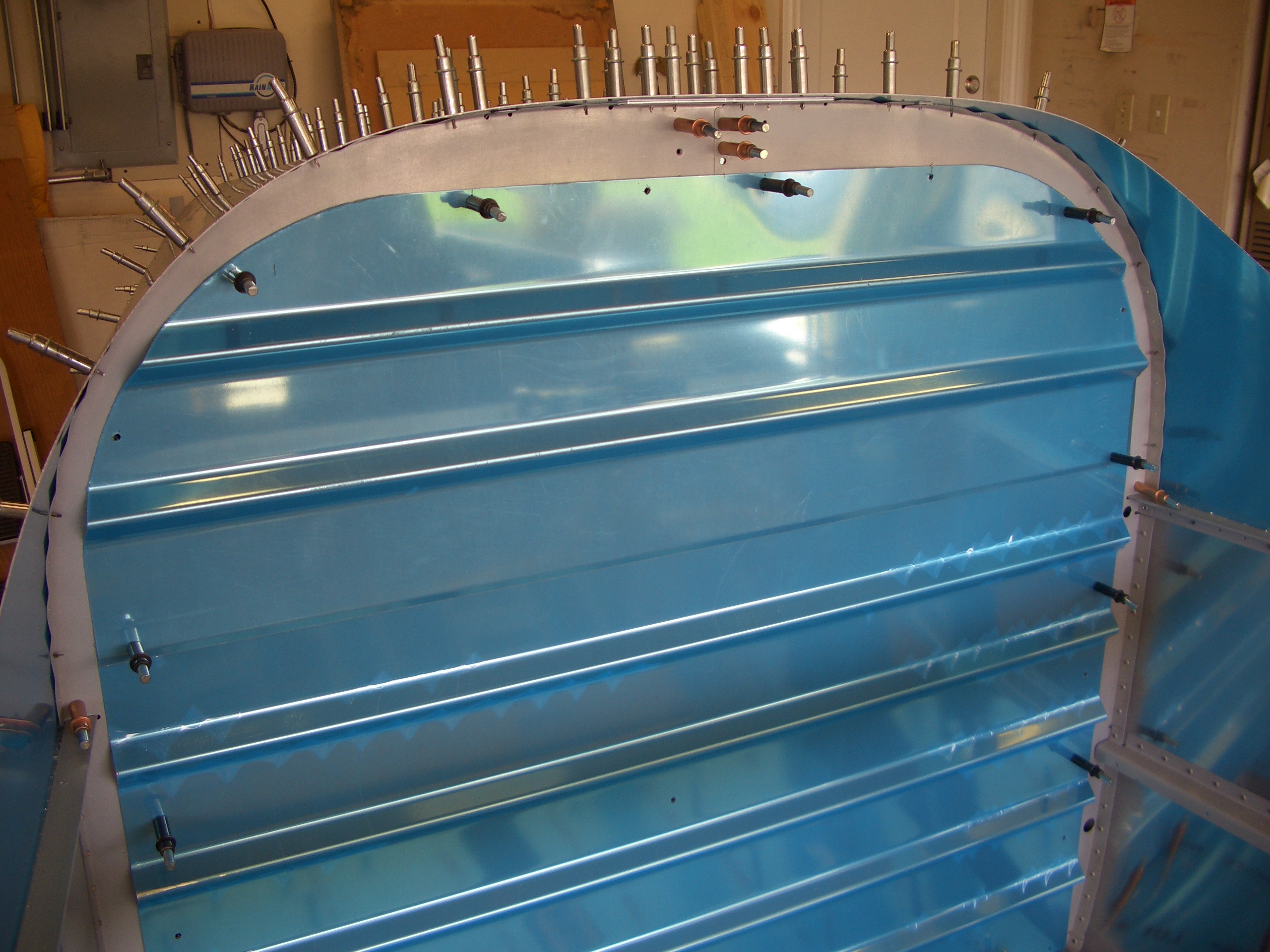
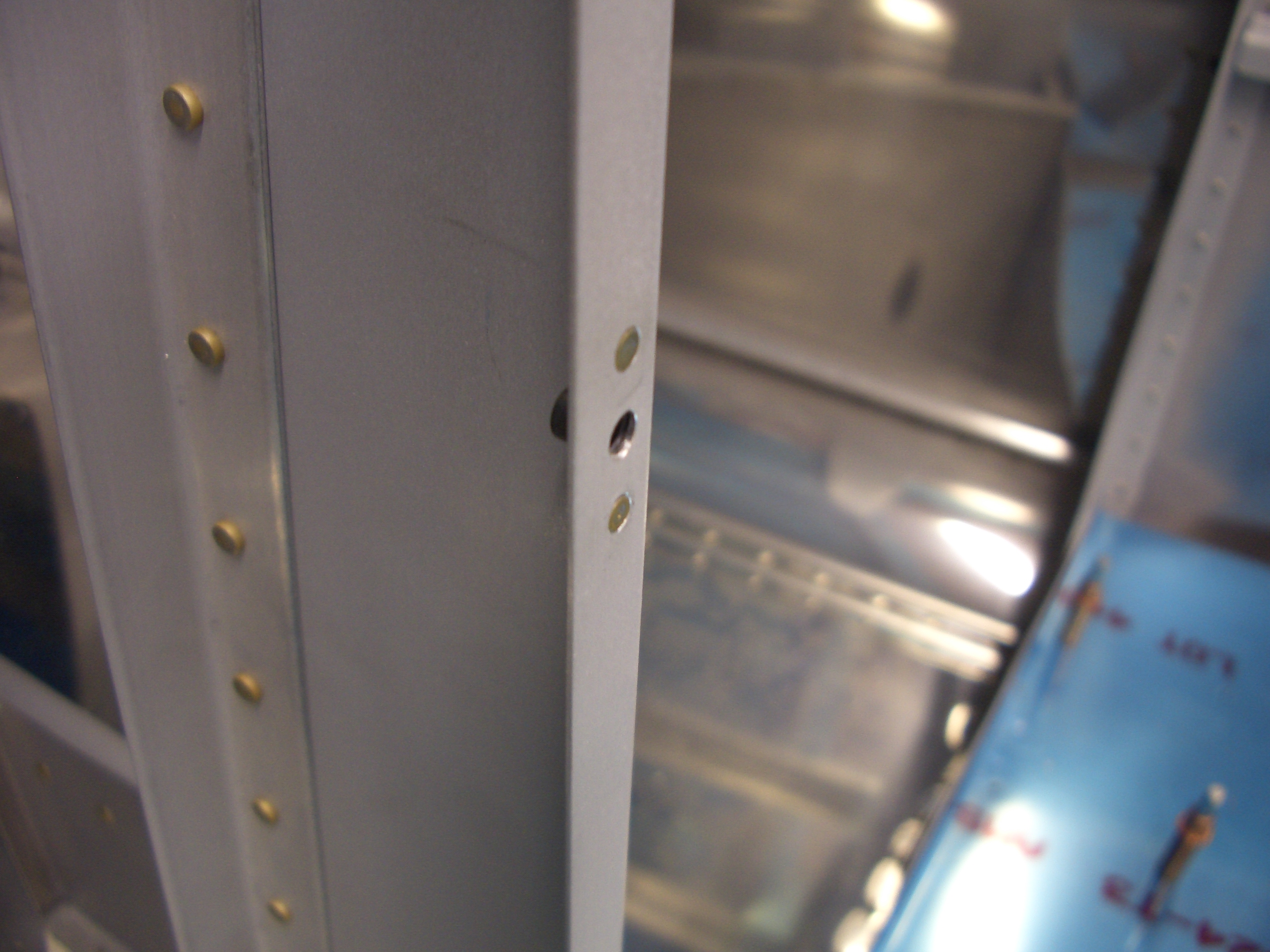
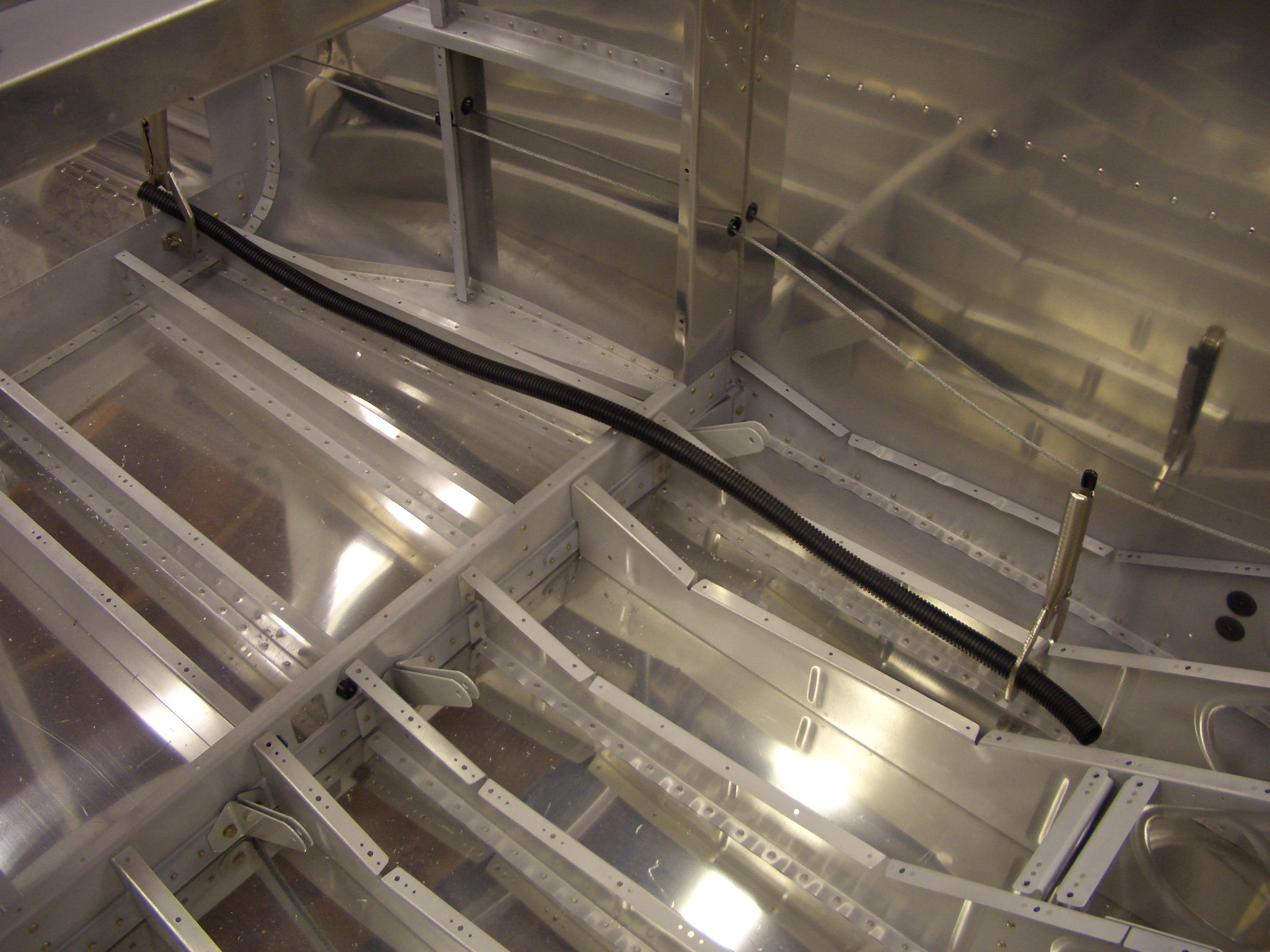
I managed to squeeze all of the remaining holes with the exception of the upper two holes in the forward flange of F-711.  I’ll have to shoot these, but it’s too late to run the rivet gun tonight.

Continued Fuselage Assembly

Now that all of the rivets along the longerons are set, the F-711D angle could be riveted to the F-711 bulkhead.  I managed to get a squeezer on these.

I positioned and drilled/reamed the seatbelt anchors just in front of F-708.  I also reamed the 1/4″ holes in the front for the bolts that attach the cable.

After drilling the F-728 angle to F-706, I riveted the reinforcing angle in place.  I was able to squeeze one of the rivets that attach F-728 to F-706 at the top.

I was also able to squeeze the upper four rivets that attach the lower end.

Fabricated Aft Deck Spacers and Elevator Bellcrank

I got started tonight by fabricating the spacers that sit under the aft deck.  Here is the one that sits on top of F-710.

And here is the slightly more complex one that sits on top of F-711.  After both were fabricated, I stuck them down with carpet tape, replaced the aft deck, and match drilled them and the bulkhead angles.

Next up, I but out the pieces for the elevator bellcrank and scotchbrited everything smooth.  I then laid out for and drilled the hole used by the autopilot pitch servo pushrod bolt.  Finally, I reamed all the holes for AN3 bolts.

Now that the position of the two ribs holding the elevator bellcrank are fixed, I match drilled and riveted the hole that ties the two angles together.

I then fabricated the two spacers that sit on either side of the elevator bellcrank bearing.  An AN4 bolt runs through these to tie the two ribs together.

Finally, I clecoed on the bulkhead gussets.  I don’t want to match drill these to the longerons yet since the bulkheads are pretty flexible at this point and it would be easy to get them in the wrong spot which would throw off the hole alignment with the top skin.

Top Aft Skins and Baggage Area

We were busy most of the day at a cub scout event with my son, but I managed to put a couple of hours in this evening.  I got started by fluting all of the bulkheads and making sure their flanges would lie flush with the skins.  I then temporarily attached the rear top skin to mark a few holes that are not predrilled.

The bottom three holes on F-709 on each side are not drilled.  I marked their position through the holes on the skin so that I can determine where to flute.  You can see that this area will need some significant fluting.

I then trimmed and fit the stiffeners and then put on the forward skin.  One final rib is inserted on the top skin between F-706 and F-707 as well as a gusset plate (where the numbers 479 are visible).

Finally, I match drilled the skins to the bulkheads and stiffeners.

Now that the skins were in place, I needed to drill the bulkhead gussets to the longerons.  Instead of peeling back the skins, I just climbed back into the tailcone and drilled the gussets in place.  For the F-706 bulkhead, I clamped a straightedge across the opening to ensure the gussets hold the two sides of the bulkhead perfectly in line with each other.

Finally, I clecoed the baggage floor back in place.

…and then clecoed and clamped the lower back wall of the baggage compartment in place.

Rear Baggage Wall

I fit and drilled the lower portion of the rear baggage wall.  The top portion needs a radius cut in it.  After measuring for the center, I taped one of my sharpie pens to an old compass and adjusted it to 8.5″ and marked the cut.  I then used some tin snips and a vixen file to trim to the line.

After laying out for the holes, I matched drilled it to the F-706 bulkhead.  It’s unfortunate that the radius of the baggage wall doesn’t match the radius of the bulkhead, but this is what the plans specify.

All of the holes need to be drilled for nutplates.

After deburring and dimpling the bulkhead, I dimpled the nutplates (the bulkhead is only 0.024″, so I didn’t want to countersink for NAS1097 rivets).  I then installed all of the nutplates that mount directly in the bulkhead.  I’m not installing the ones that also rivet to the baggage floor since I’m not ready to rivet that in yet.

The F-728 rib needs several nutplates where the wall attaches.  Since this is 0.040″, I countersunk for NAS1097AD4 rivets.

Installed Rudder Cables

I installed the rudder cables tonight, mostly because I couldn’t think of a good reason not to.  The rudder cables run through snap bushings installed in every bulkhead from F-902 to F-710.  The front end of the cable has en eyelet that is larger in width than the inner diameter of a SB625-7 snap bushing, so the eyelet must be forced through the snap bushing before it is installed in the bulkhead.

Where the cable exits the side of the aircraft just in front of the rudder, the cable passes through a plastic sleeve so that the cable doesn’t rub against any metal parts.  The sleeve is held in place by an adel clamp that is secured by the flush phillips screw that is just above and in front of the rudder cable exit hole.  I’m going to buy or fabricate a little exit fairing to hide the plastic sleeve (not because I think it will lower drag, but I think it will look nicer than the plastic sleeve just sticking out of the hole).

Seat Belt Anchors and Static Ports

I installed the seat belt anchors tonight.  Other than it being pretty cramped where the outboard anchors attach, making it difficult to get a torque wrench in there, these were pretty straightforward.  I clamped a piece of scrap 1/4″ thick steel between each pair of anchors and used an AN4 bolt to keep the upper holes aligned while I torqued these down.

Next, I laid out and drilled for the static ports.  I’m using the SafeAir pitot/static/AOA kit, so the flange of the static port doesn’t allow you to install them precisely where Van’s recommends (11/16″ forward of the vertical row of rivets).  The position I used is 2″ down from the horizontal row of rivets and 1 1/4″ forward of the vertical row of rivets).  Here I’m holding the SafeAir static port in the hole while trying to take a picture.  I had a hard time getting my camera to focus on the static port, so this is a little blurry.

I mixed up a small batch of proseal and bonded/clamped these in position.  I installed the 90º adaptors in the ports before doing this so that I could ensure both of them are pointing upward.  I’m not going to use any rivets to secure the ports since the proseal is plenty strong to secure these.

Static System and Fuselage Deburring/Dimpling

I fit a piece of the static system tubing between the two static ports.  There is a tee on the right that will allow a single piece of tubing to connect between here and the instruments.

After fabricating the clip that ties the top center rib to the F-707 bulkhead, the lower two rivets can be squeezed.

Next up, I deburred every hole on the fuselage structure (not the holes on the pieces that have yet to be attached permanently to the fuselage structure).  I also dimpled all of the bulkhead holes.

Finally, I played around a little bit with conduit routing under the baggage floors and seat pans.  I’m routing the conduit through the outboard baggage bays since I plan to use the inboard bays for storage.  This also puts the conduit one bay outboard of the area containing the crotch strap and control columns.  This is likely to be a packed area.

Started Baggage Floor Compartments

I’ve decided to put storage compartments in the two larger bays below the baggage floors.  After doing some measurements and mocking it up in the computer, I cut a hole in one of the floors.

I fabricated a reinforcing ring that wraps around three sides of the hole.  There will be a hinge along the fourth side.  The joggle at the two ends allows the reinforcing ring to step up onto the hinge so that the corner rivets tie all three pieces together.

Worked on Left Baggage Floor

After fabricating the door and cutting holes for the hartwell latches, I test fit the floor in the plane.

Here is a closeup of one of the hartwell latches.  They make a crazy number of models of these, but four of the eight I bought off eBay were the same, so I used those.

To open the door, you push in on the button marked “PUSH” (duh)…

and the other part of the latch springs open.

Once both latches are released, the door can be opened.  The reinforcing ring provides a lip that the door can be closed against (and the latches catch under).