Worked on Baffles

I’m waiting on some sheet stock from Aircraft Spruce to make the canopy side skins (I can’t use the stock included in the kit because I moved the joint line forward to line up with the longeron bend and it isn’t long enough).  I decided to pick back up on the baffles since I like to have multiple parts of the aircraft under construction simultaneously.  I managed to get the whole rear wall and left side wall rough fit.  Here’s a view of the rear wall on the right side.  This piece required quite a bit of trimming to fit around the upper engine mount bolt.

Here’s a view of the left rear wall.  The recessed portion will eventually contain a hole for the oil cooler.

And here are the pieces that make up the left side wall.  You can see here that small doublers are riveted on where the screws attach the baffles to the cylinders.

Here’s roughly where the oil cooler will be mounted.  Since I’ve installed an IO-375, Bart at Aerosport recommended I install the Stewart Warner 10599R instead of the more common 8432R.  This is over 1″ wider than the 8432, so the fit is snug.  Even with the oil cooler touching the engine mount (I will eventually cut away a notch to give some clearance), the flange sticks past the edge of the baffles.

Here’s a look from the front side showing that the mounting holes in the oil cooler stick past the edge of the baffles.  I will need to fabricate a mounting bracket to support this.  I’m not ready to do anything on it yet though since the plans recommend waiting until the baffle seals are installed and then positioning the oil cooler as high as possible.  There is also still a small chance that I’ll mount the oil cooler on the firewall.

More Work on Baffles

I drilled and riveted on a support brace to the right aft wall.  It was a mistake to rivet this on now as it makes installing the right aft wall very difficult.  Since this wall has to go on and off a bunch of times before it’s on for good, I’m going to drill this brace out.

I drilled the vent attach flange.  This is not the cheesy one that comes in the kit.  Instead, I purchased a single piece flange from Aircraft Spruce.  The hole pattern for the included flange doesn’t work, but this will cover the existing holes, so I just drilled four new ones.

Here’s the crappy little flange that’s included in the kit.  Everyone says these break eventually, so I’m just going to send it back.

I also fit the vent screen.  This will keep bugs and other shit from getting blown into the cabin.

Baffles and Ignition Coils

I fit the remaining sidewall and riveted the stiffener on the sidewall above cylinder 3.

The center of the aft wall needs a stiffener to brace it.  This is the bracket that comes with the baffle kit.  You can see that it interferes with the installed position of the lightspeed ignition coils.  I’m going to try moving the coils forward so that I can install this bracket relatively unmodified.

I’m going to have to modify this bracket somewhat though since the holes don’t line up with the case.

I cut off the aft flange of the bracket.

This allowed the bracket to slip aft enough for the holes to line up.  I’ll end up riveting an angle to the aft edge to replace the flange I cut off, but I’m going to wait until I fit the cowl since this might have to get cut down a bit.

I slipped some bolts into the bracket to see how things line up.  I reformed the fuel line to cylinder 4 to clear the bracket by about 1/4″.  I also reformed the steel attach bracket on the right so that it raises up the mounting point for the adel clamp..

I set up a straight edge to get an idea where the top of the cowl will be located.  I’m going to move the ignition coils forward by by about an inch from their original location and raise them up a bit to clear the spider.

I sketched out a bracket on some 1/8″ angle stock that will allow the ignition coils to be mounted to two case bolts instead of one.  The aft hole for this bracket was the mounting point for the original bracket.  It’s nearly two in the morning, so I’ll cut this out tomorrow.

Fabricated Ignition Coil Bracket

The switch on my small belt sander stopped working, so I had to fix that today.  Fortunately, it was a double pole switch and only one side went out.  I hardwired the neutral through and I’m only switching the hot wire.

I spent about 30-45 minutes cutting out the bracket I drew up last night.  I still have to finish the edge of the lightening hole and drill the top for the coils, but it looks like it fits great.

Here’s how the coils will mount to the bracket.  Plenty of clearance all around.

After drilling the holes, I temporarily mounted the coils and hooked up the ignition wires (which I’m sure are in the wrong spots).

Here’s a shot from the front showing the vertical clearance.  The wires are at least 1/4″ from the spider mounting bracket.  Once they’re secured with adel clamps to the push rod tubes, these won’t touch anything.  It also looks like I’ll have at least 1″ of clearance between these and the top cowl.  That should be plenty to prevent these from ever touching the cowl.  Once I’m happy with the fit of everything, I’ll paint these brackets the same color as the baffles.

Worked on Right Front Baffles

The desiccant pellets on the engine have turned pink a couple of times and I’ve microwaved them to turn them back to blue.  However, about half of them have turned a light orange color and microwaving them didn’t turn them back.  I don’t know if microwaving them is the problem or not.  I’ll try using the oven next time.

I stopped by the new Harbor Freight store near work and picked up a 1kg bag of desiccant pellets for $5.  This should be a lifetime supply of these things.

I refilled the drying plugs on the engine, so I should be good to go for a couple more months.

Anyway, I resumed working on the baffles by bolting the front baffle support to the engine case.

I then assembled and drilled the front right baffle assembly.  Since I have a constant speed prop, I drilled out a 1″ diameter hole for the grommet that will fit around the prop oil line.

Here you can see how the assembly fits on the engine.  You can also see that I disconnected the oil line from the fitting in the case.  I put a plug in the line and a cap on the fitting to keep debris out of the line since this will be disconnected until the baffles are installed for good.

I used a set of large pliers to stretch one of grommets around the fitting on the oil line.  When the baffles are installed for good, I’ll slide this up and fit it into the hole I drilled earlier.

Riveted Right and Left Front Baffles

shot a little primer on the mating surfaces and riveted together the right front section.

I then installed it.  There’s only one screw holding it in place now, so it fits a little loose.

I then drilled and riveted all of the pieces for the left front section (minus the air dam which I installed after this picture was taken).

Fitting this to the engine took quite a bit of reshaping along the inner edge the follows the curve of the case.  It fits really well now and follows the case snugly.

Installed Propeller

In order to make progress on the baffles, I need to fit the cowl.  In order to fit the cowl, I need to install the prop.  This took much longer than I thought.  There are six bolts that hold the prop to the crankshaft flange, and they can each only make about one turn before they bind and you have to move on to the next bolt.  That ended up taking about a half hour.  What took even longer though was getting the spinner back plate installed.  There is very little room for fingers or tools between the back of the prop hub and the back plate.

Worked on Cowl Clearance

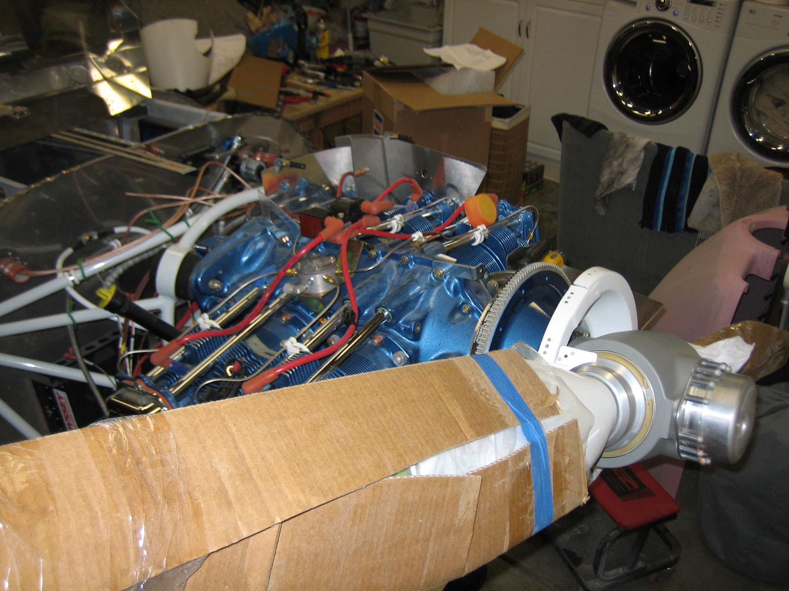
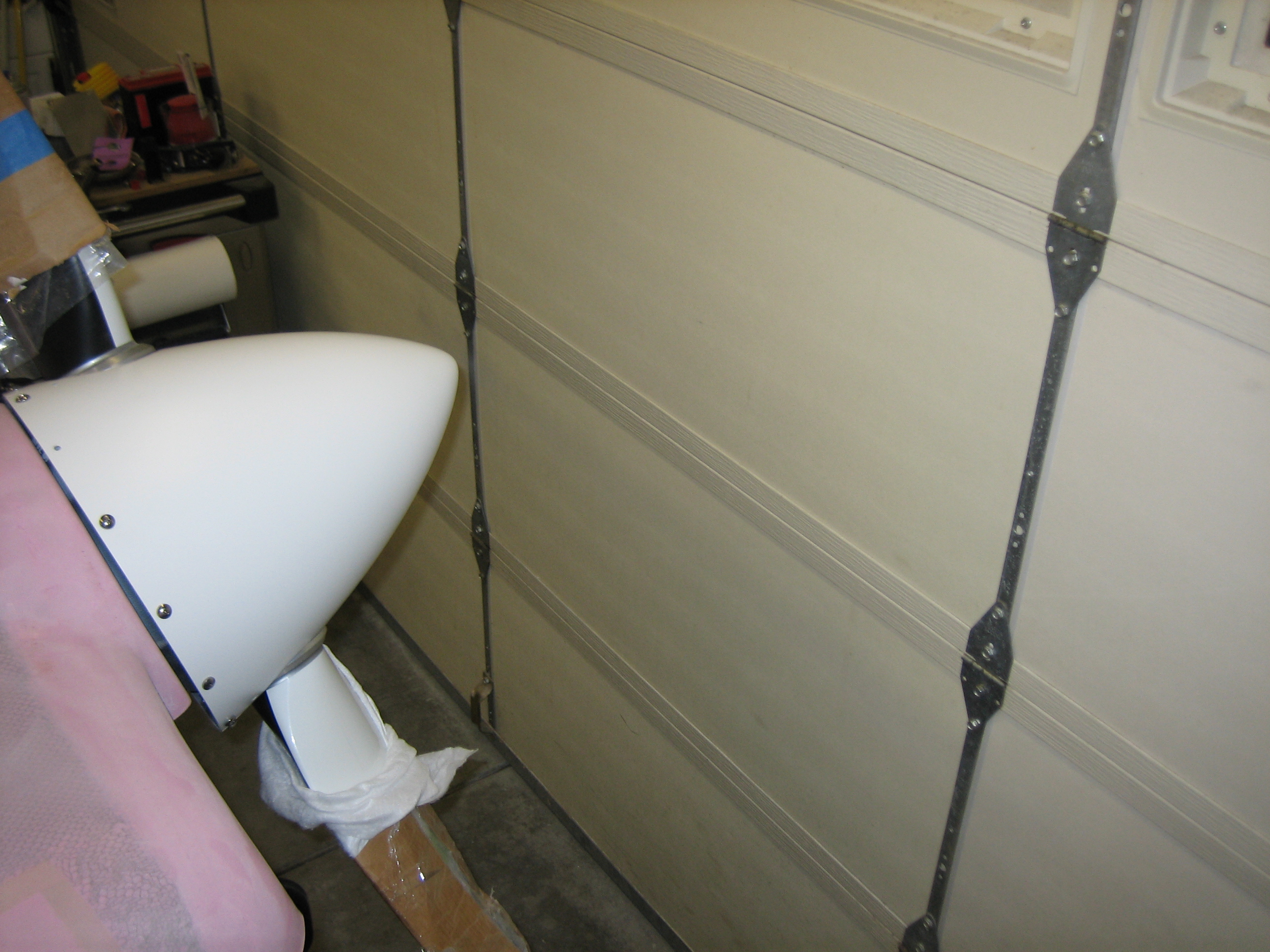
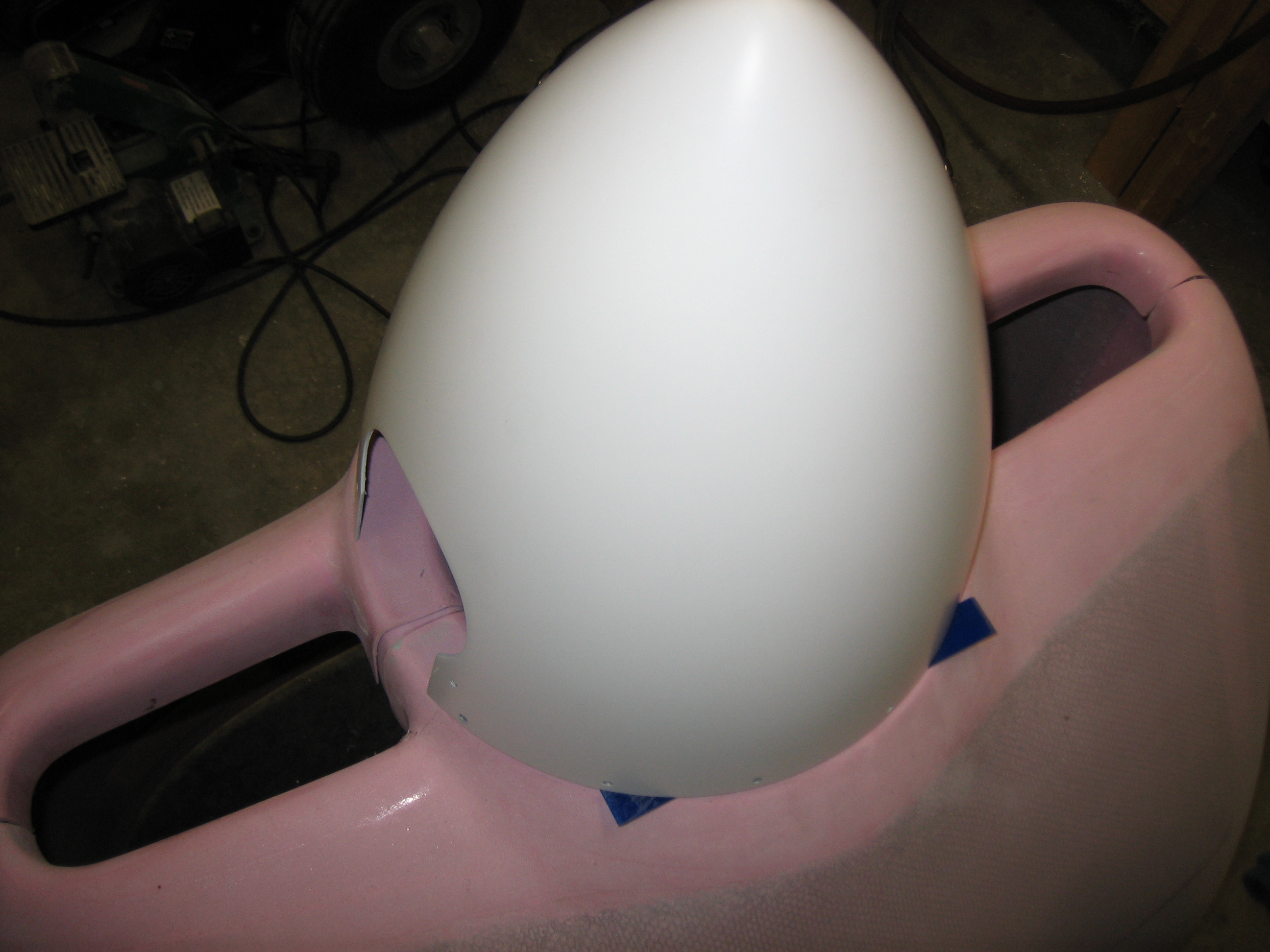
I finished installing the spinner and then threw the top cowl up to see what kind of clearance I have on top of the engine.  I put a piece of 3/4″ thick scrap wood on top of the flywheel to space the cowl up so that it lines up with the spinner.

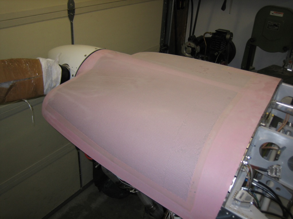
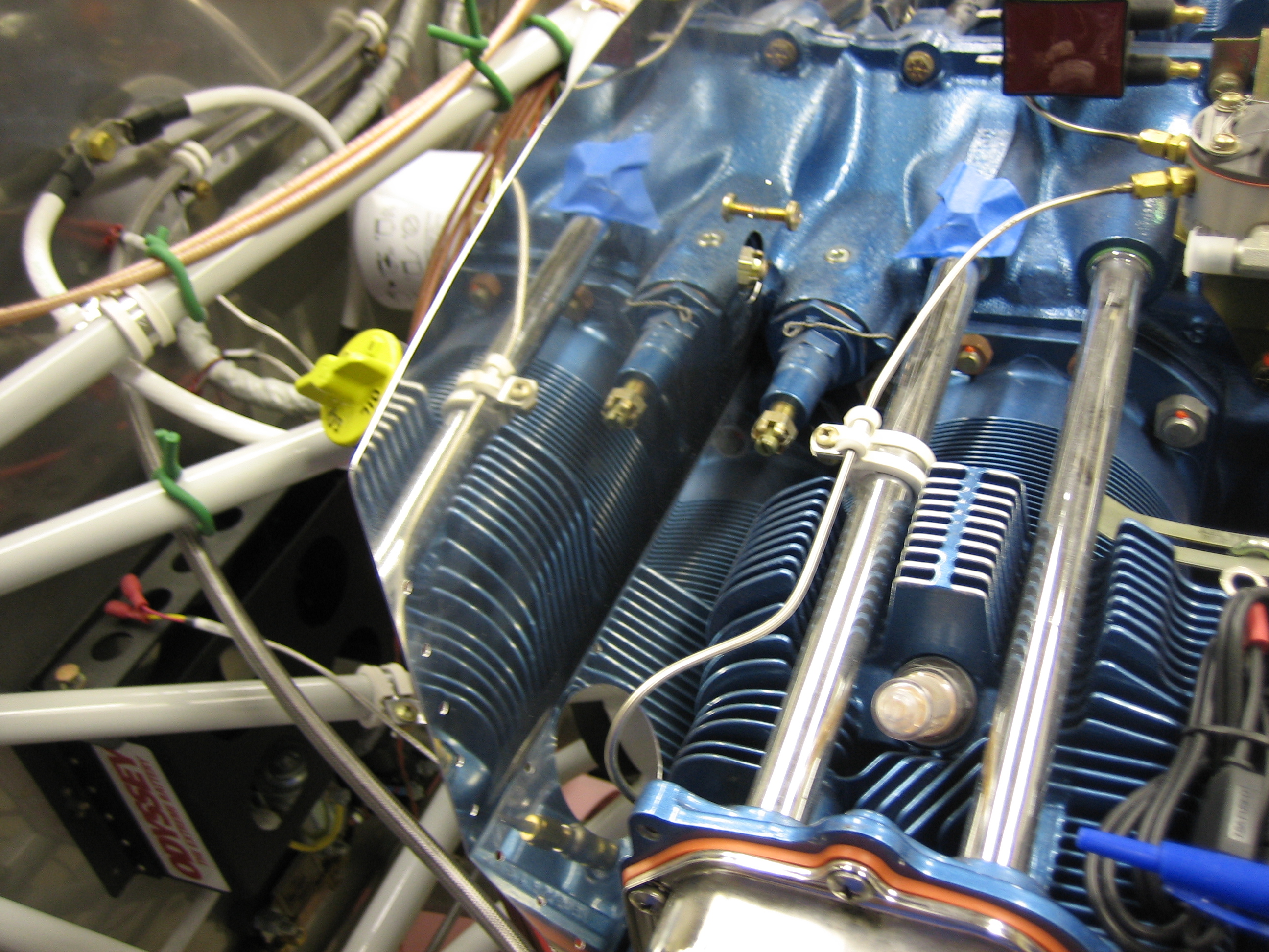
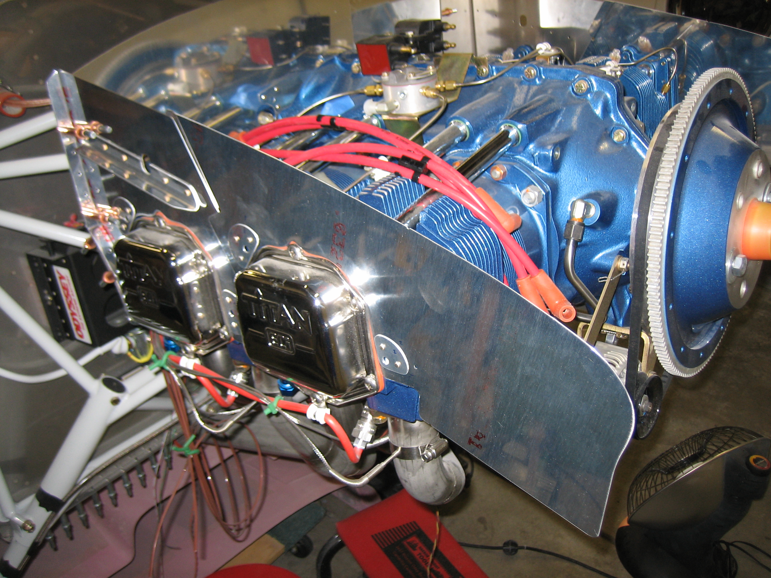
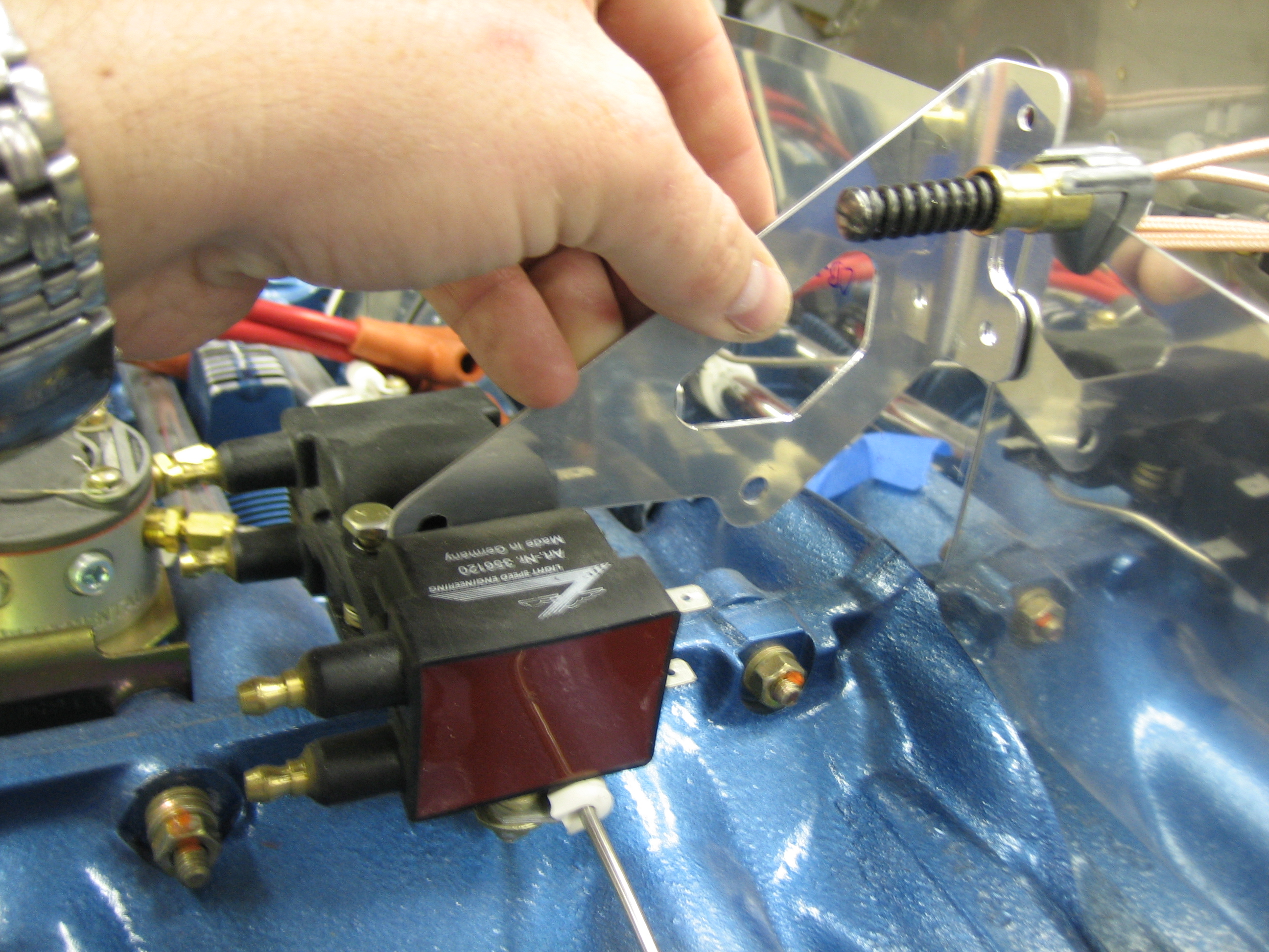
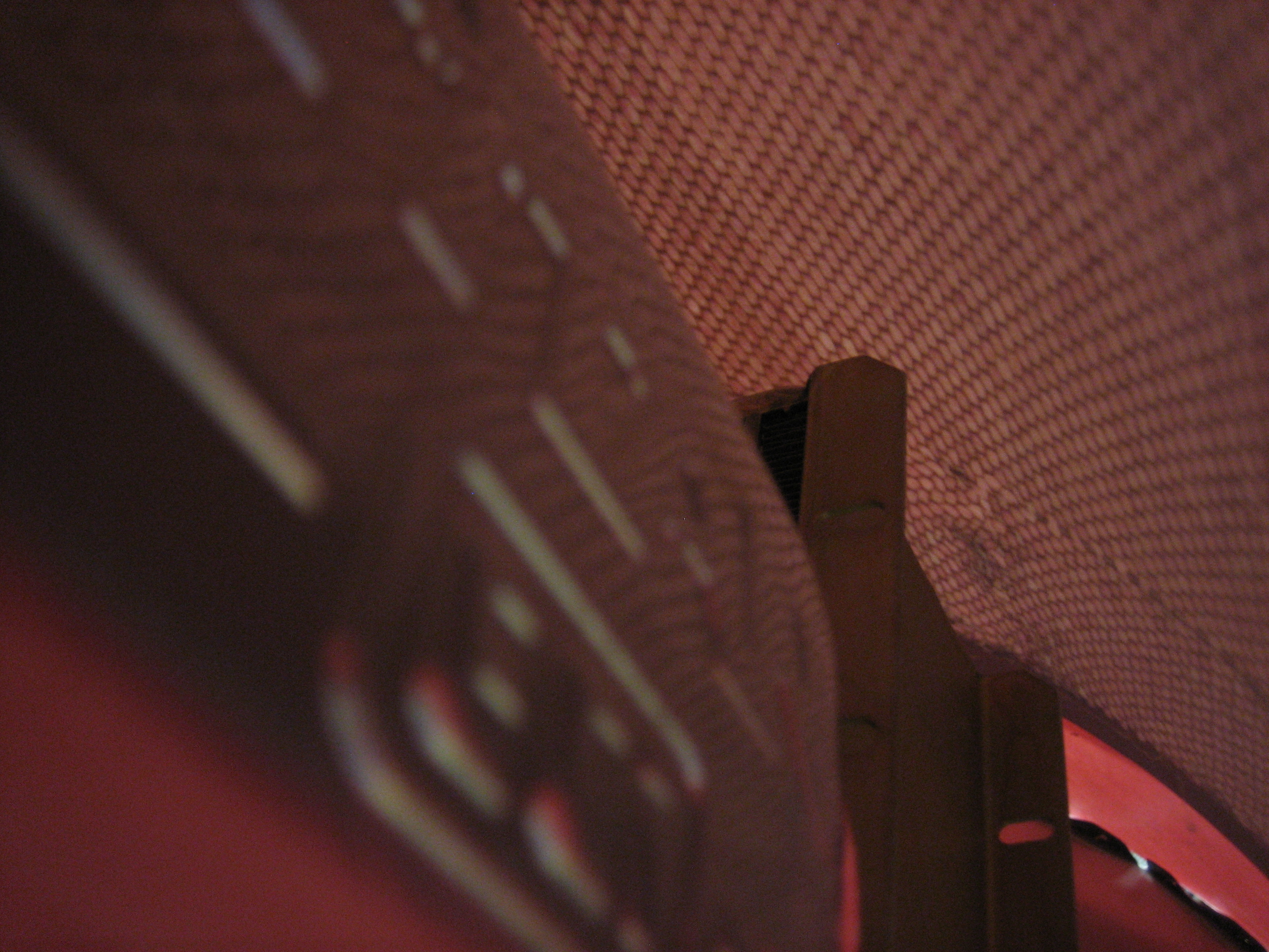
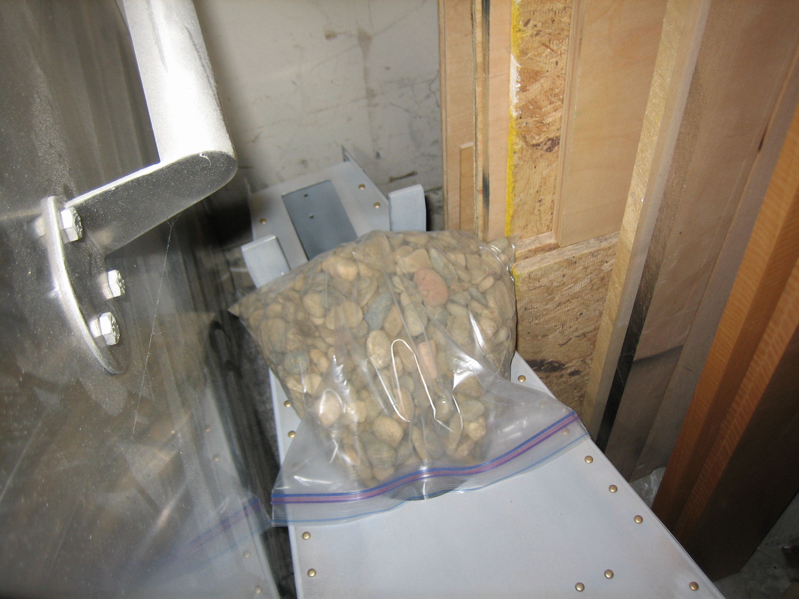
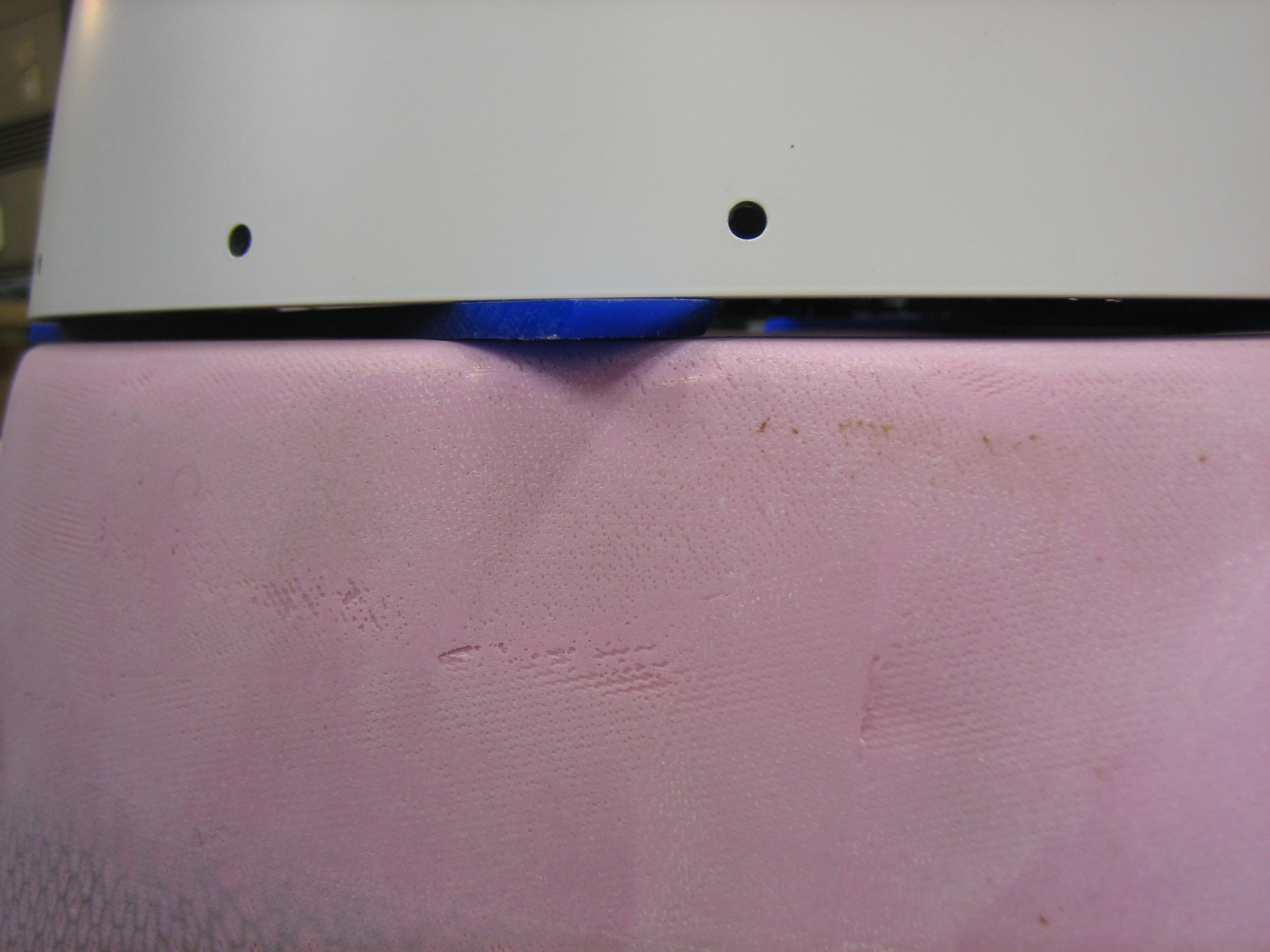
With the lightspeed coils moved forward and installed on the taller bracket, I only had about 1/4″ between the coils and the bottom of the cowl.  This certainly isn’t enough clearance.  On top of that, I’ve decided to install a plenum instead of baffle seals, this means I need even more clearance that I would if I were installing baffle seals.

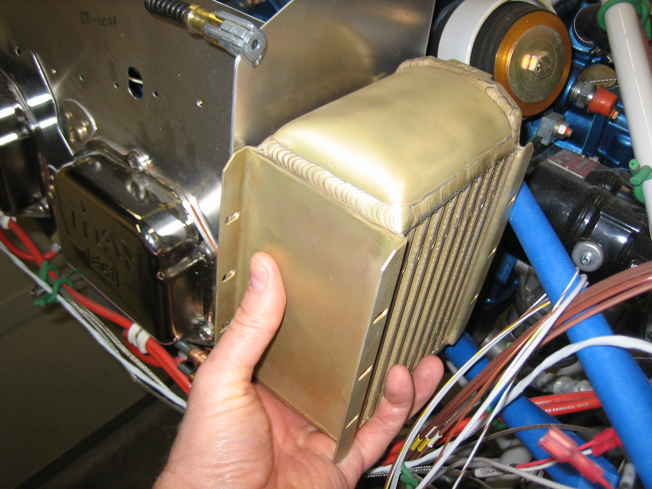
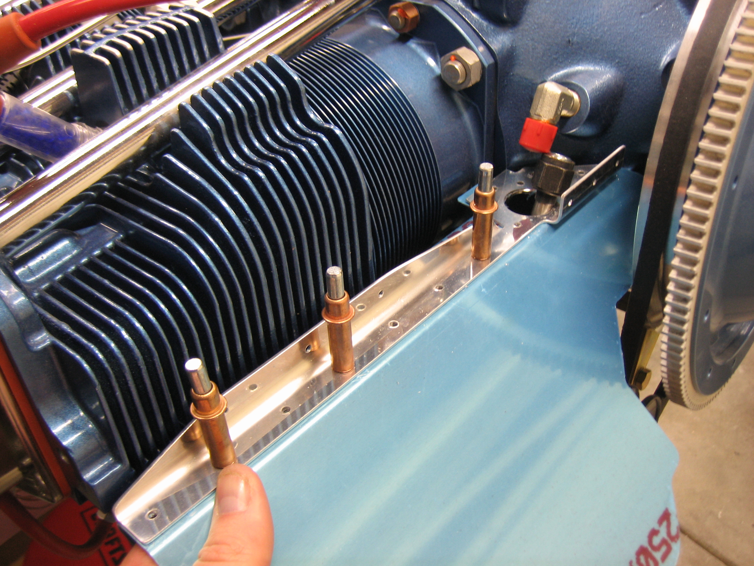
While I had the top cowl roughly in position, I wanted to see how high the oil cooler could be mounted.  It looks like I can go up to the point that the center hole in the flange is aligned with the upper engine mount tube.

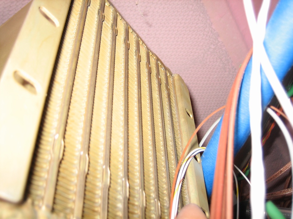
It’s hard to see here, but this still gives me about 1/2″ clearance between the oil cooler and the cowl (even if I don’t relieve the end of the mounting flange a little more).

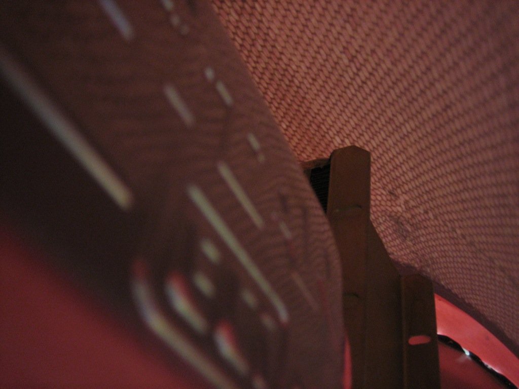
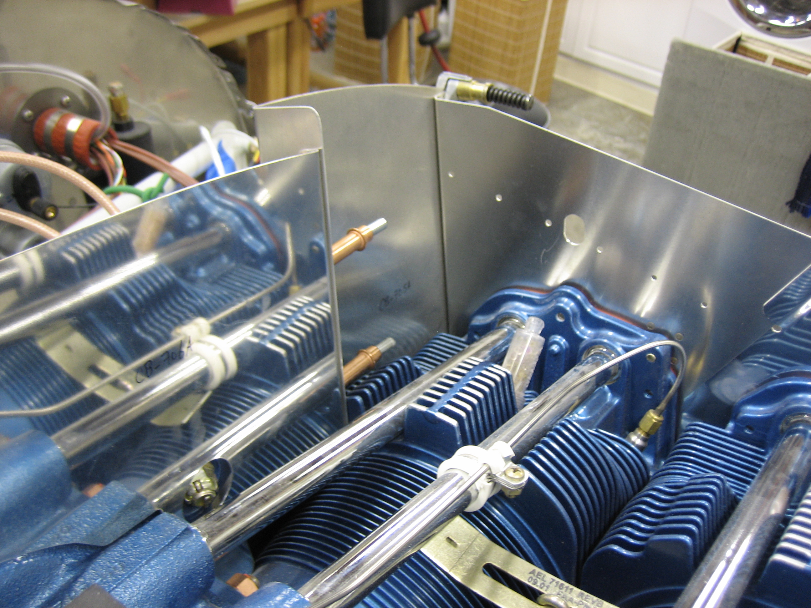
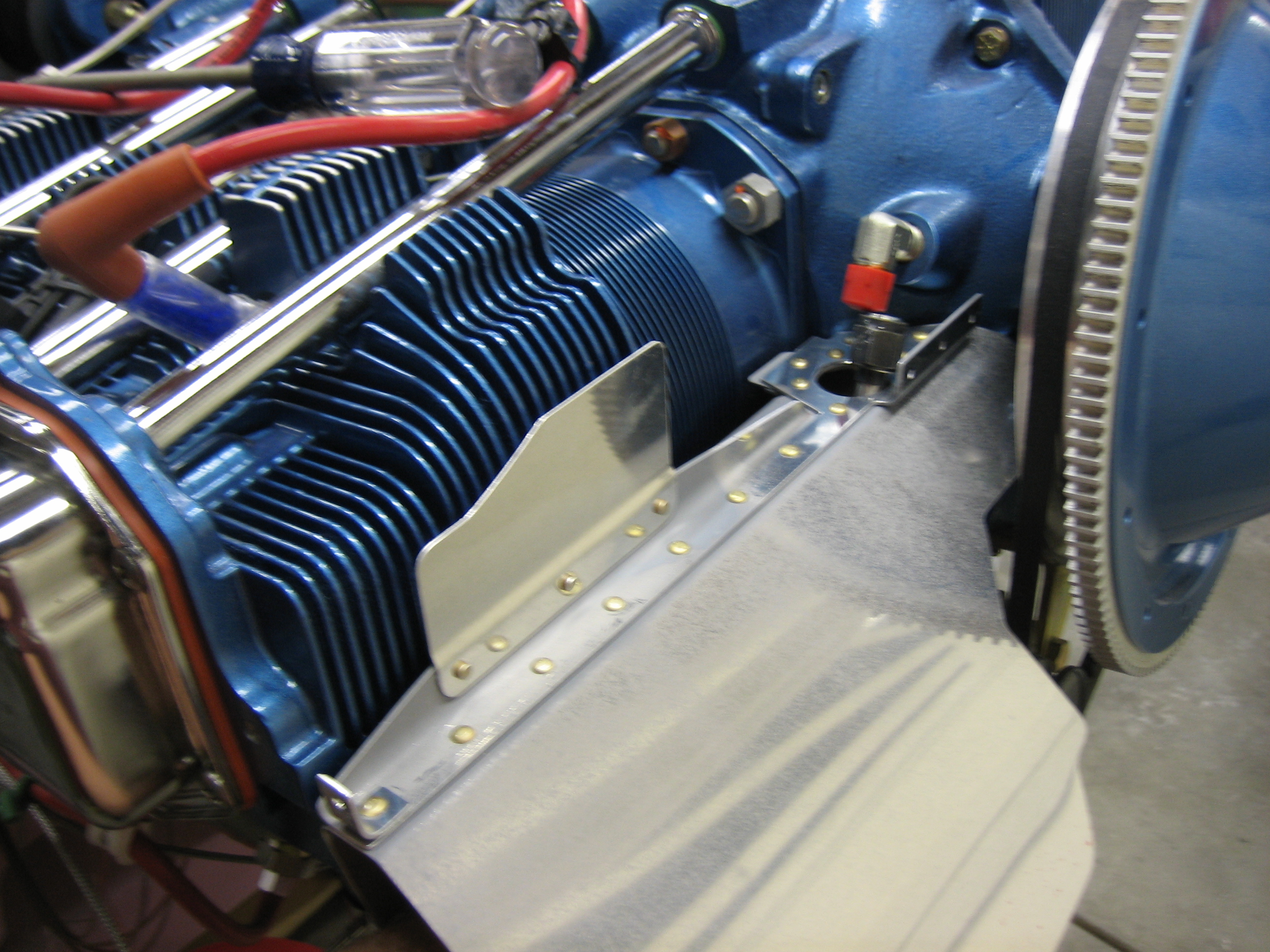
I took a picture of the rear part of the top of the engine.  Because of the way the cowl slopes, there is a lot more height farther back.

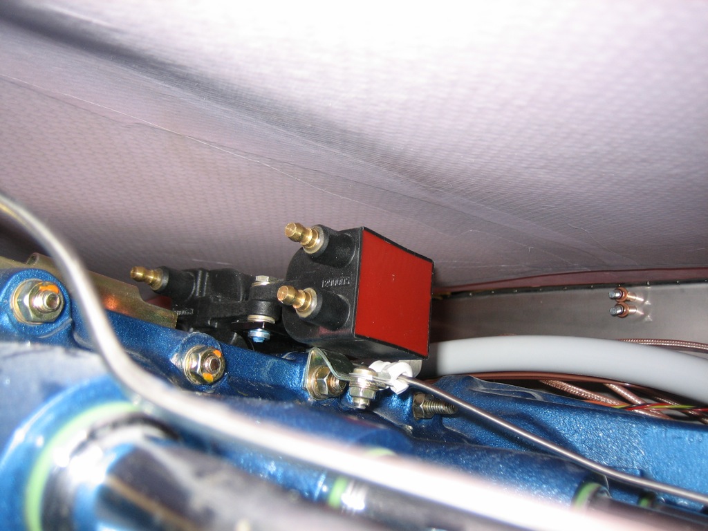
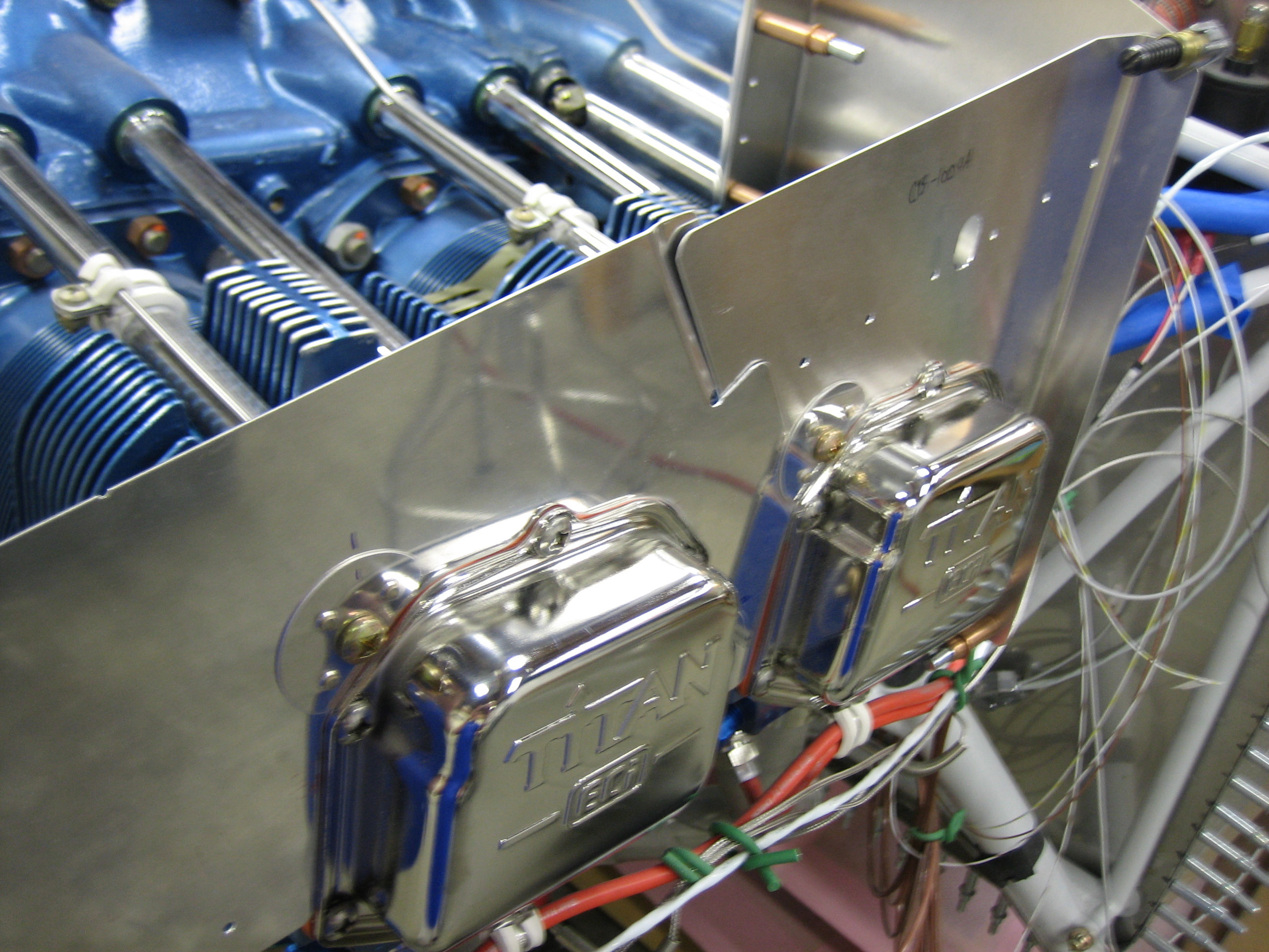
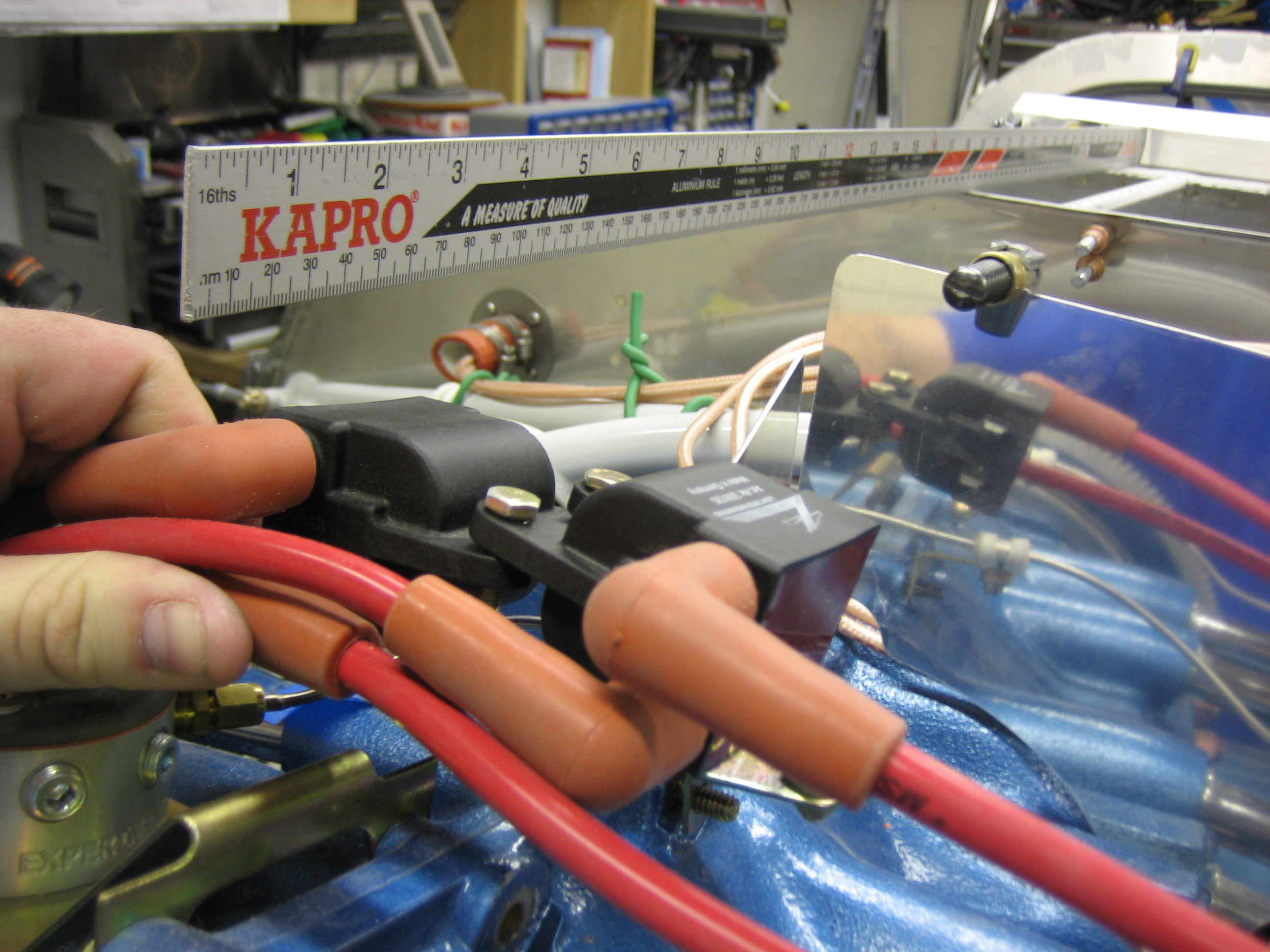
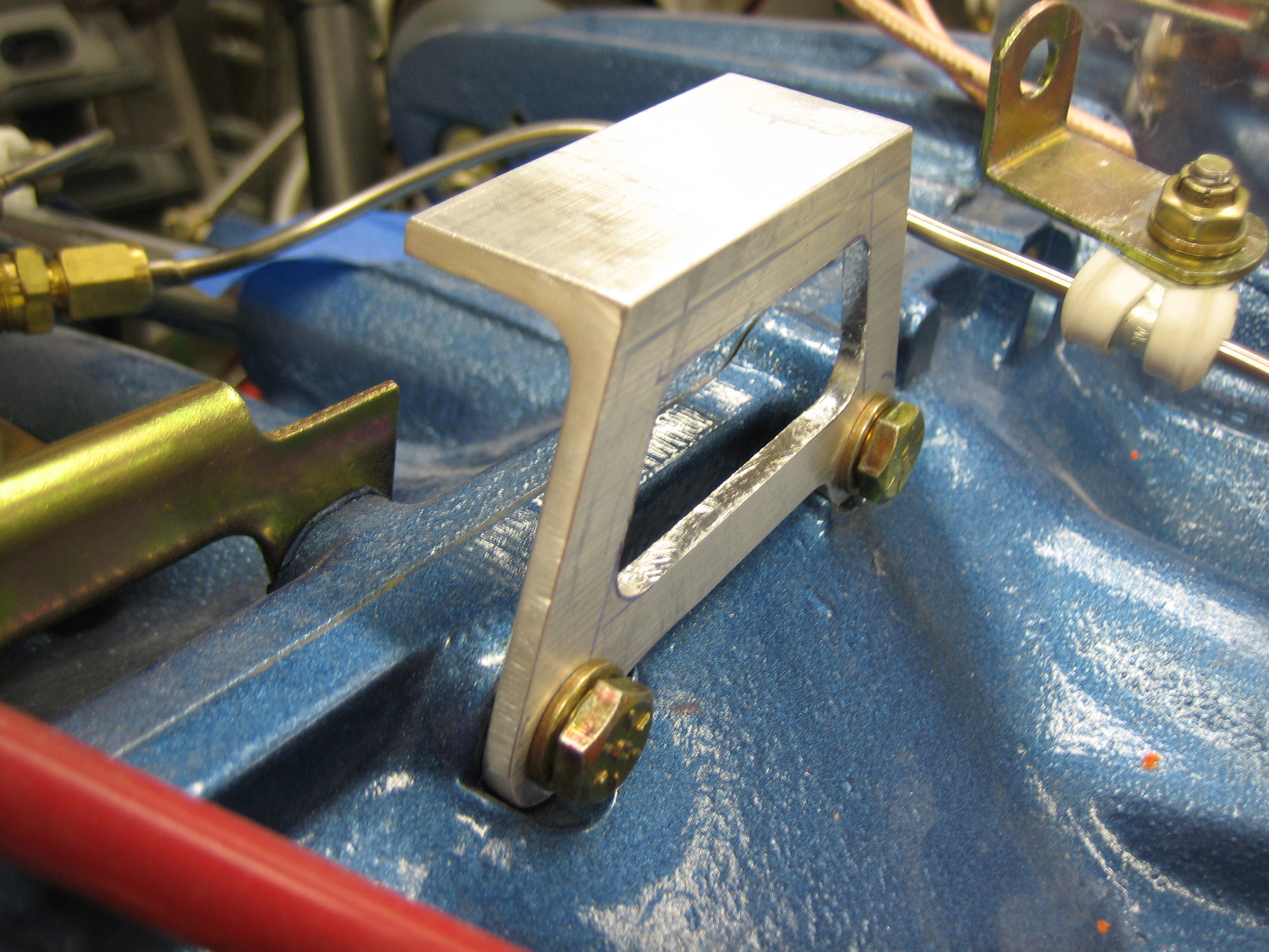
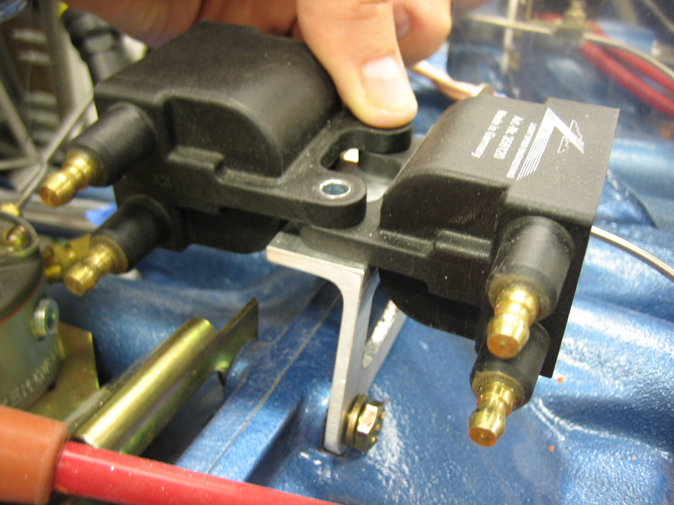
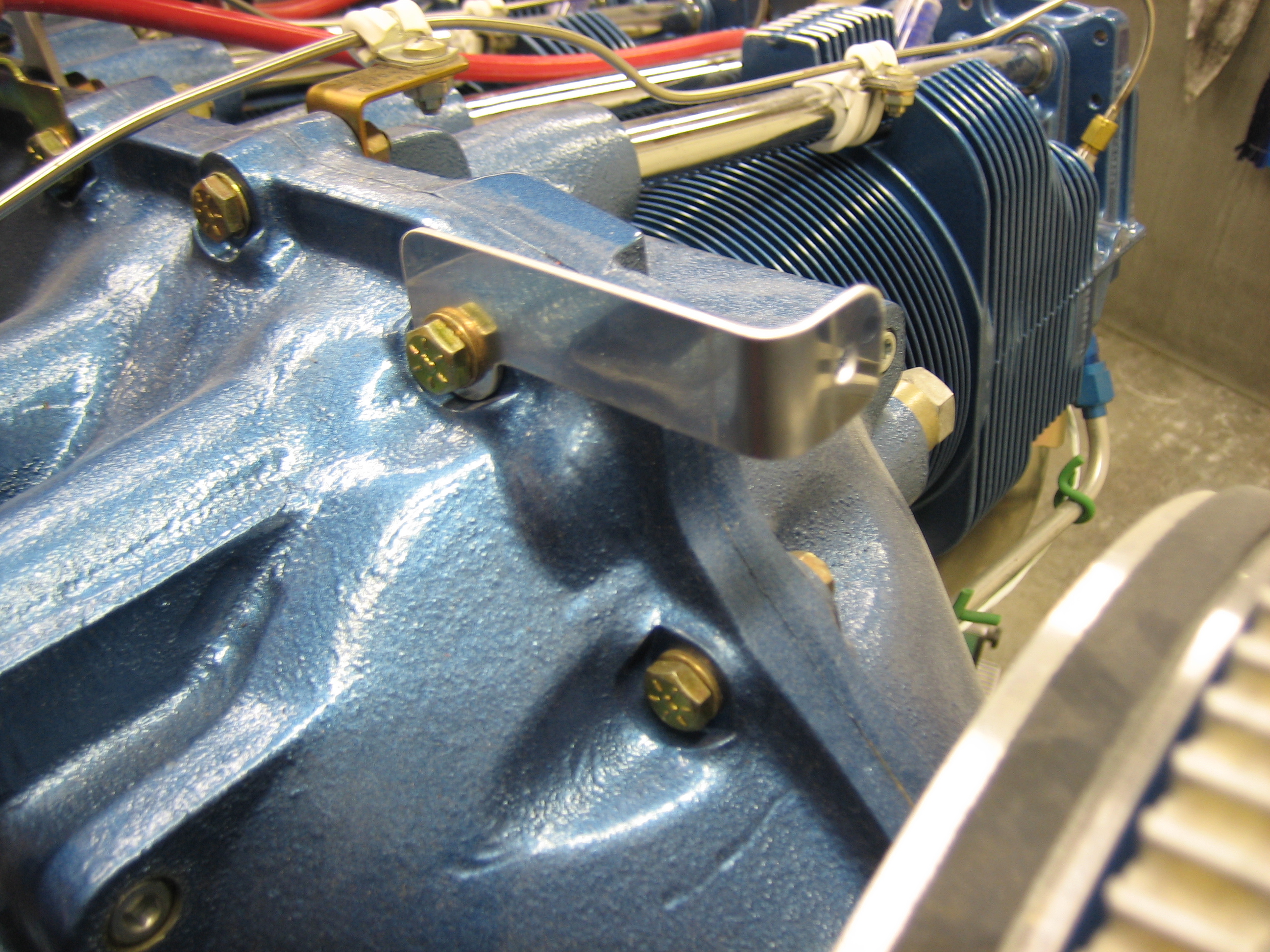
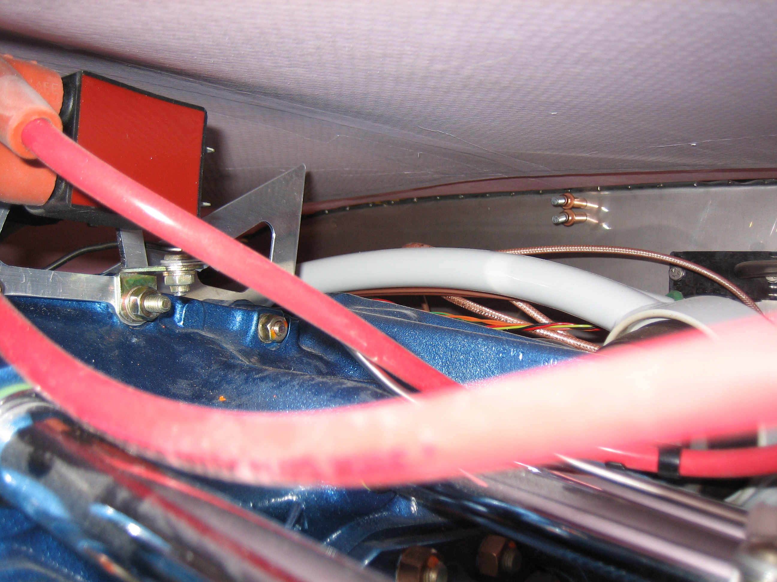
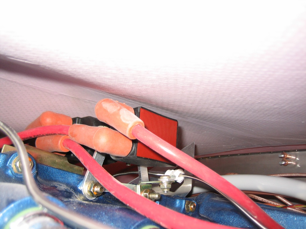
I moved the ignition coils back to the original mounting bracket.

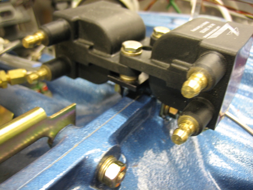
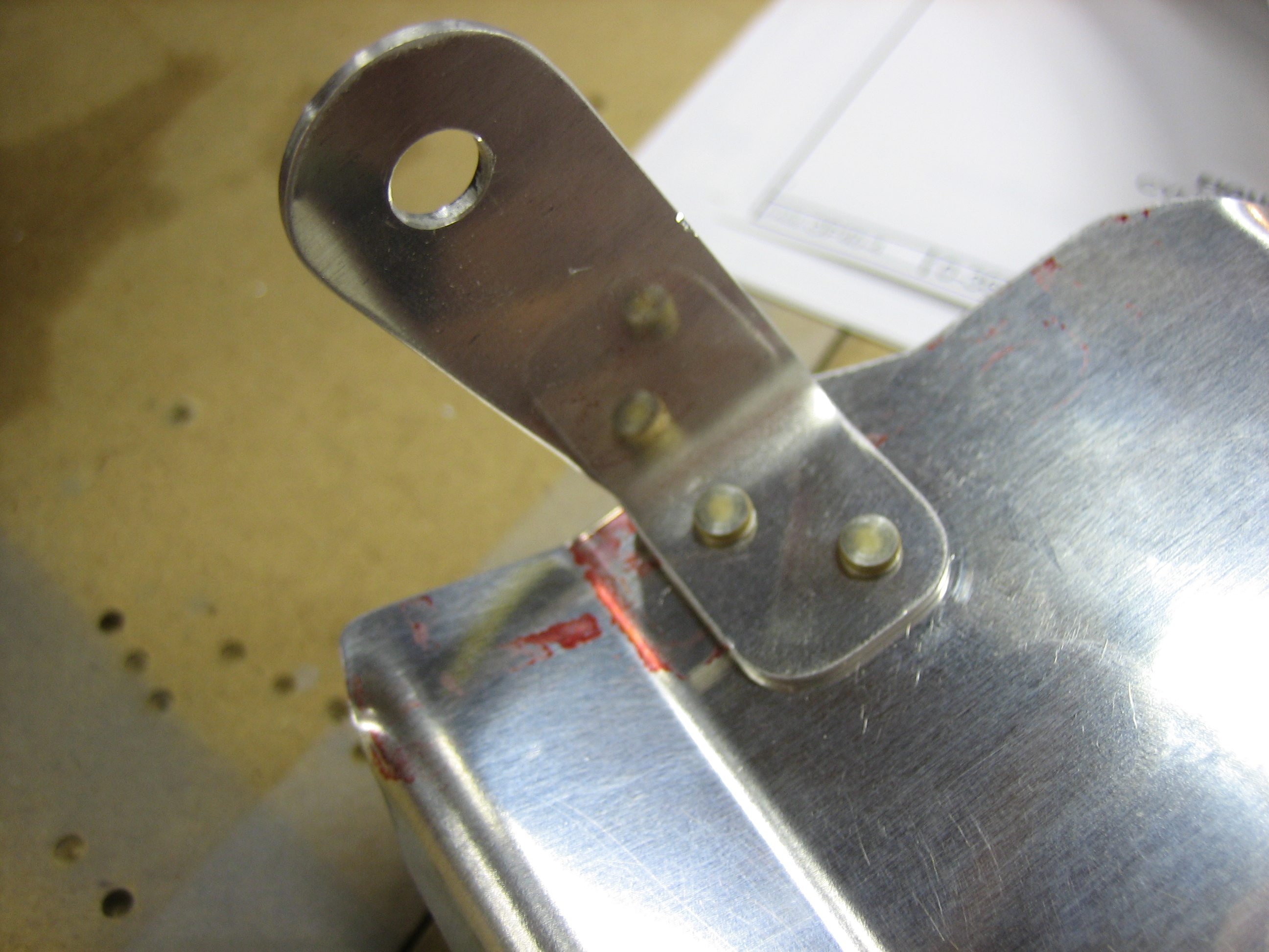
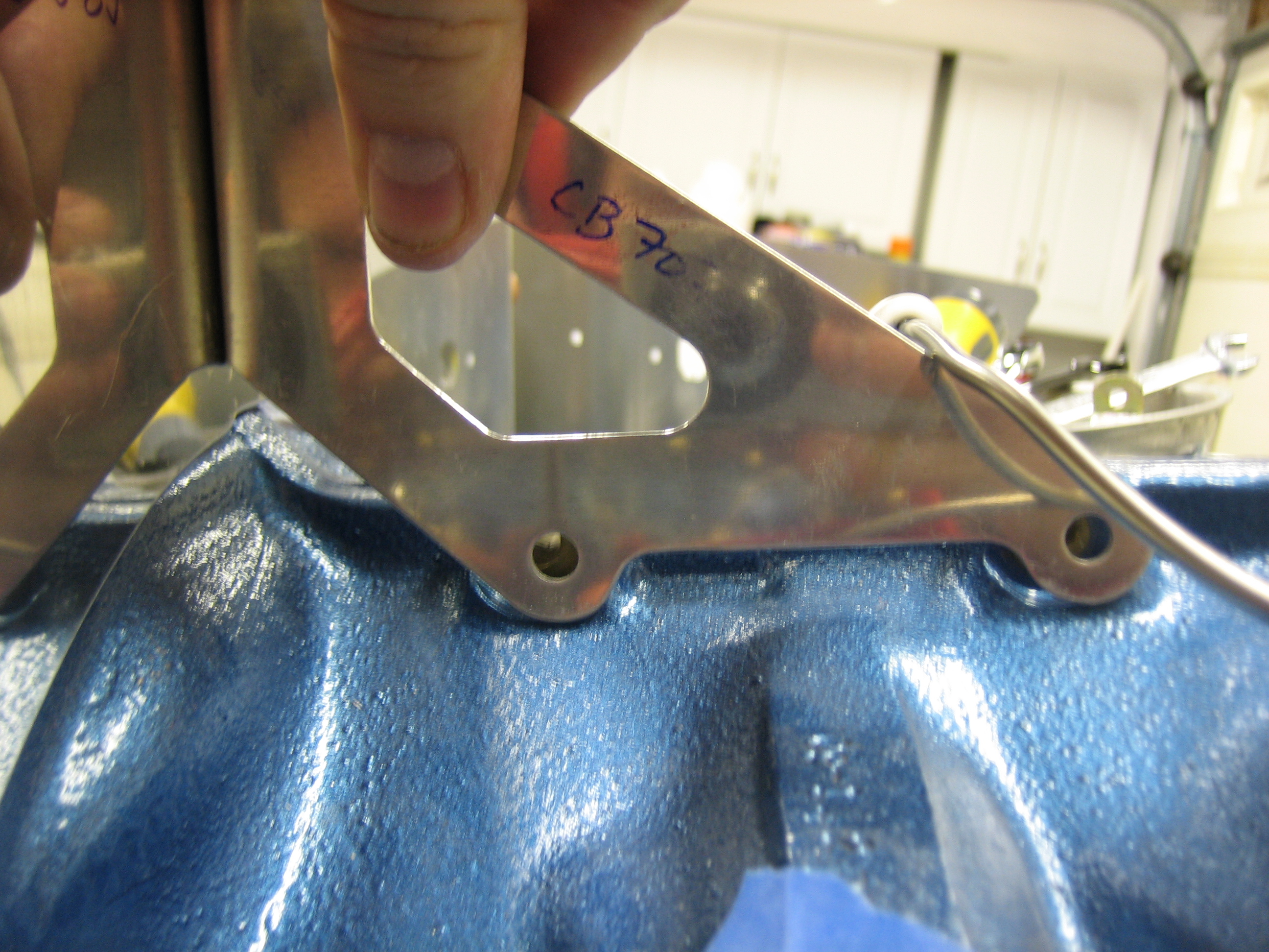
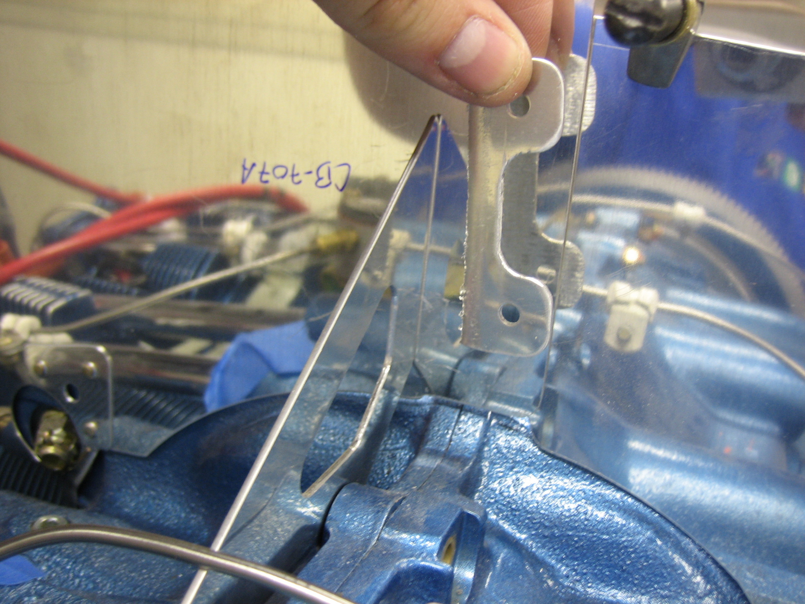
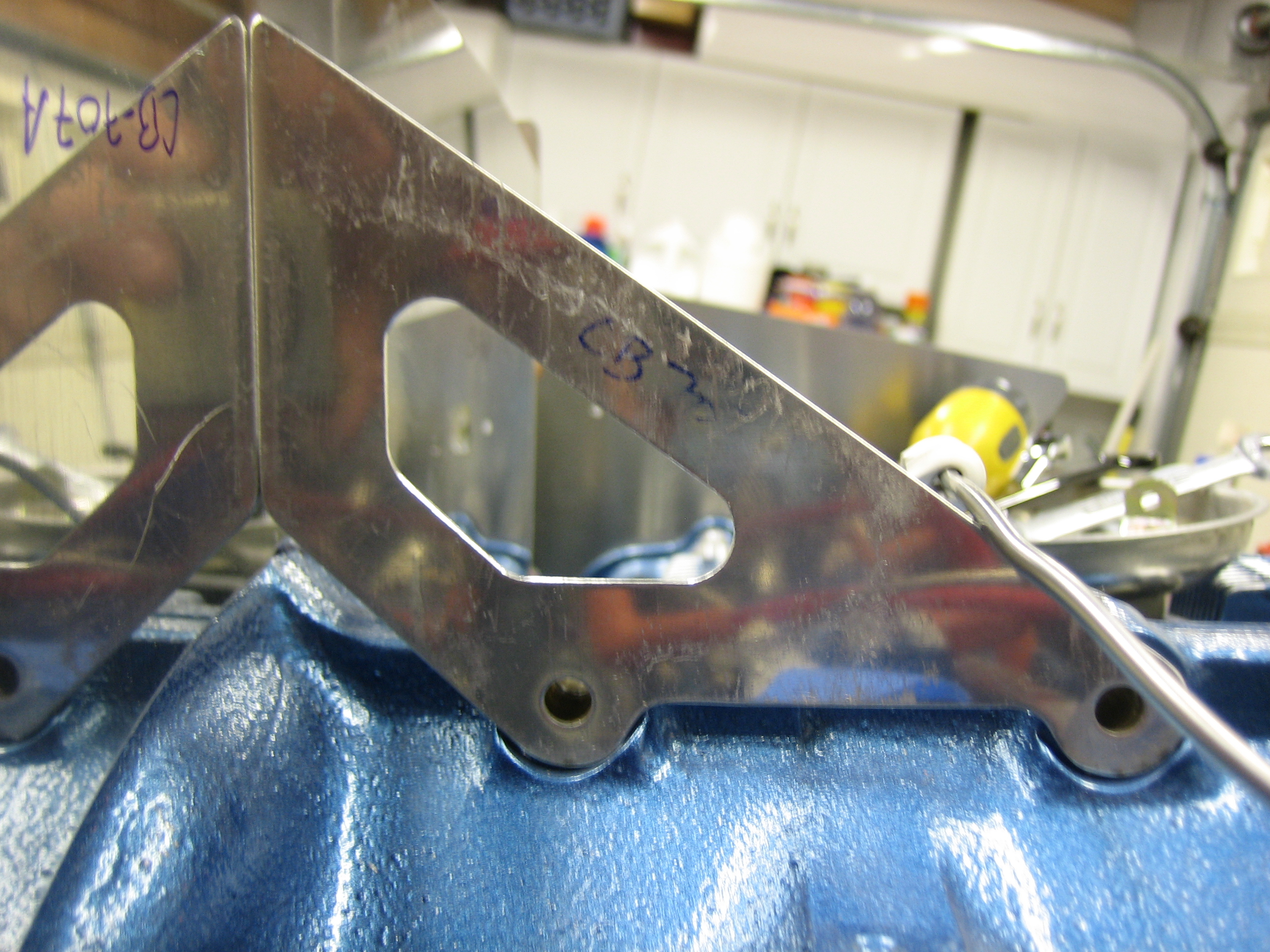
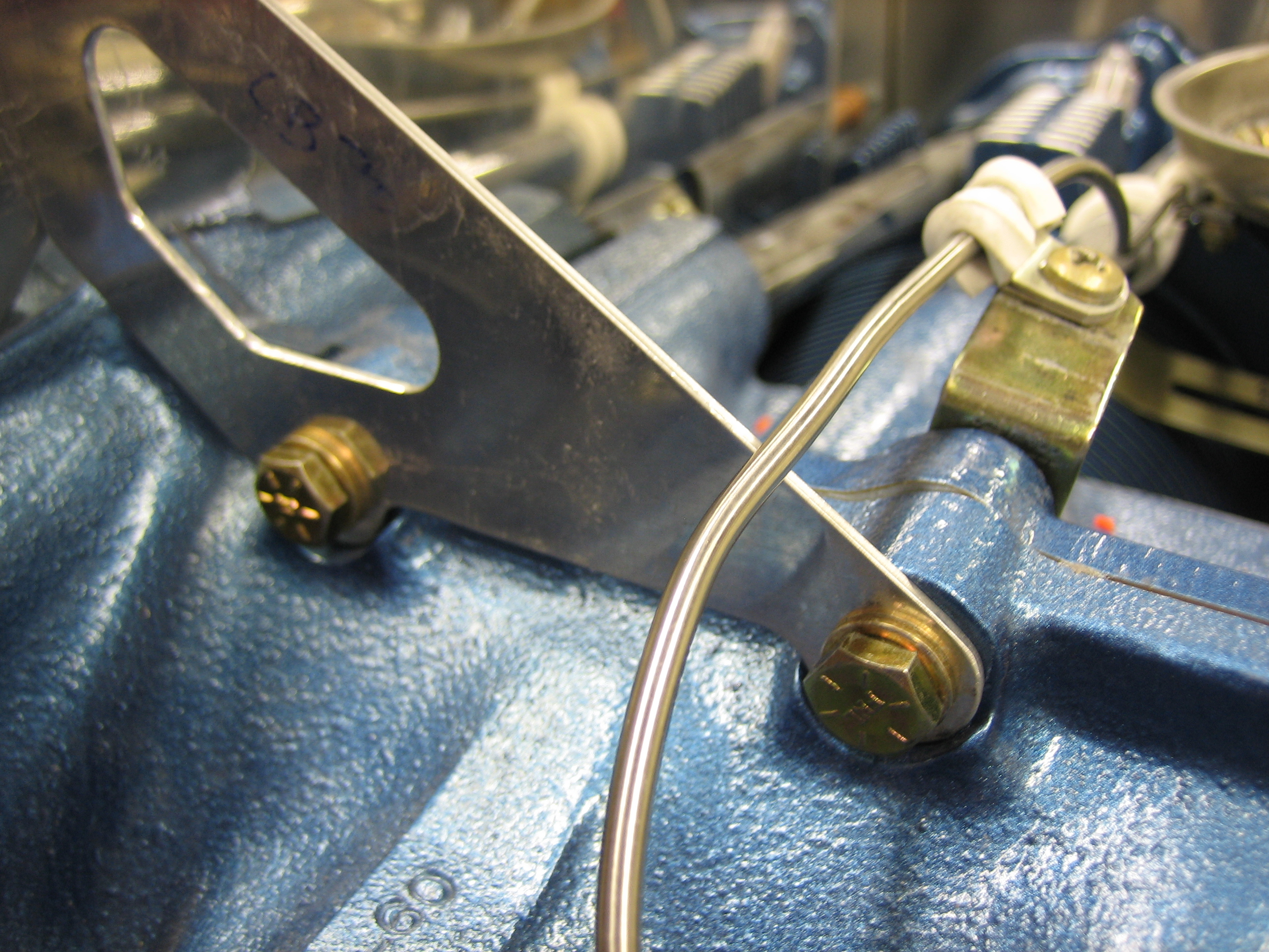
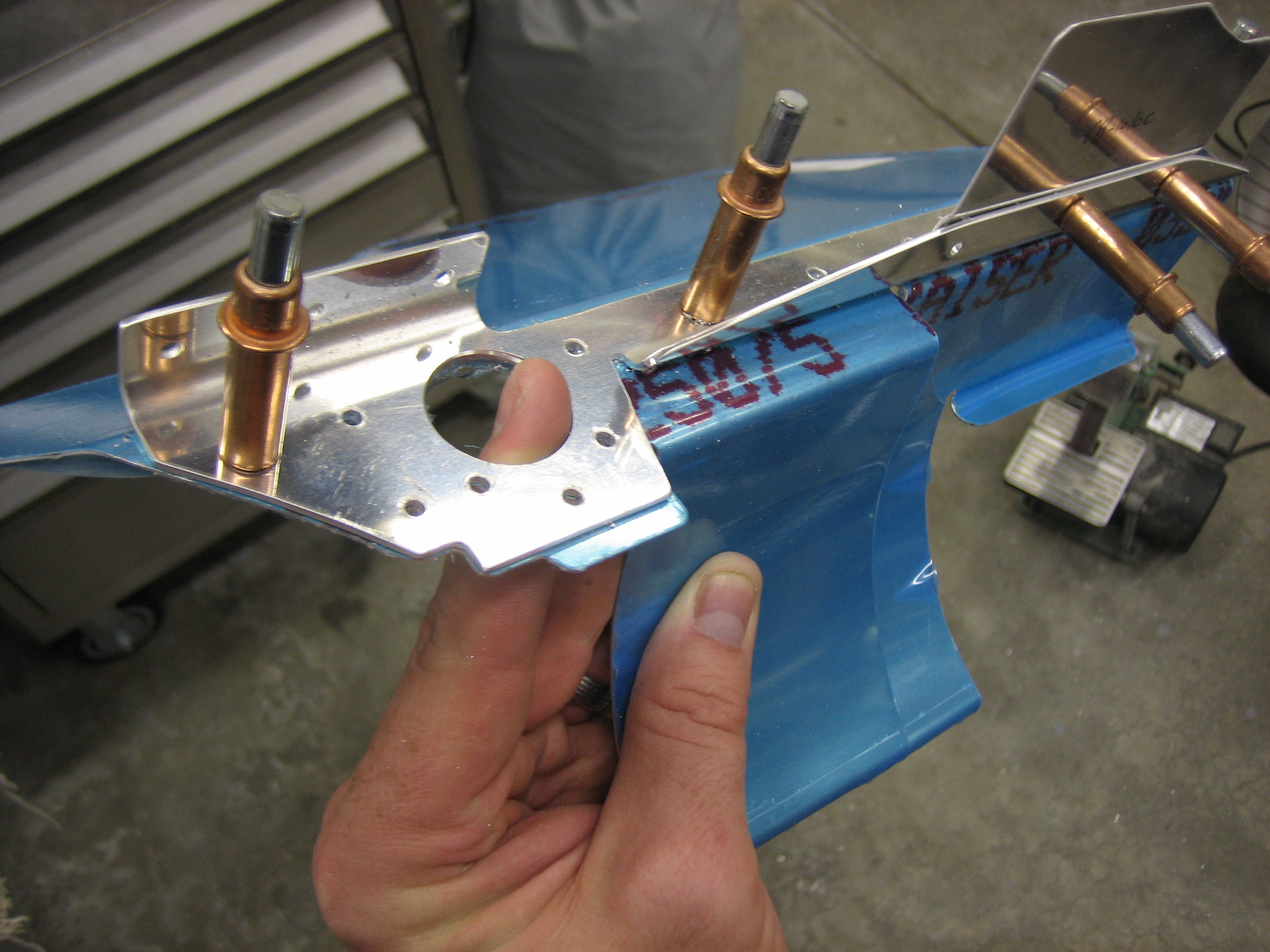
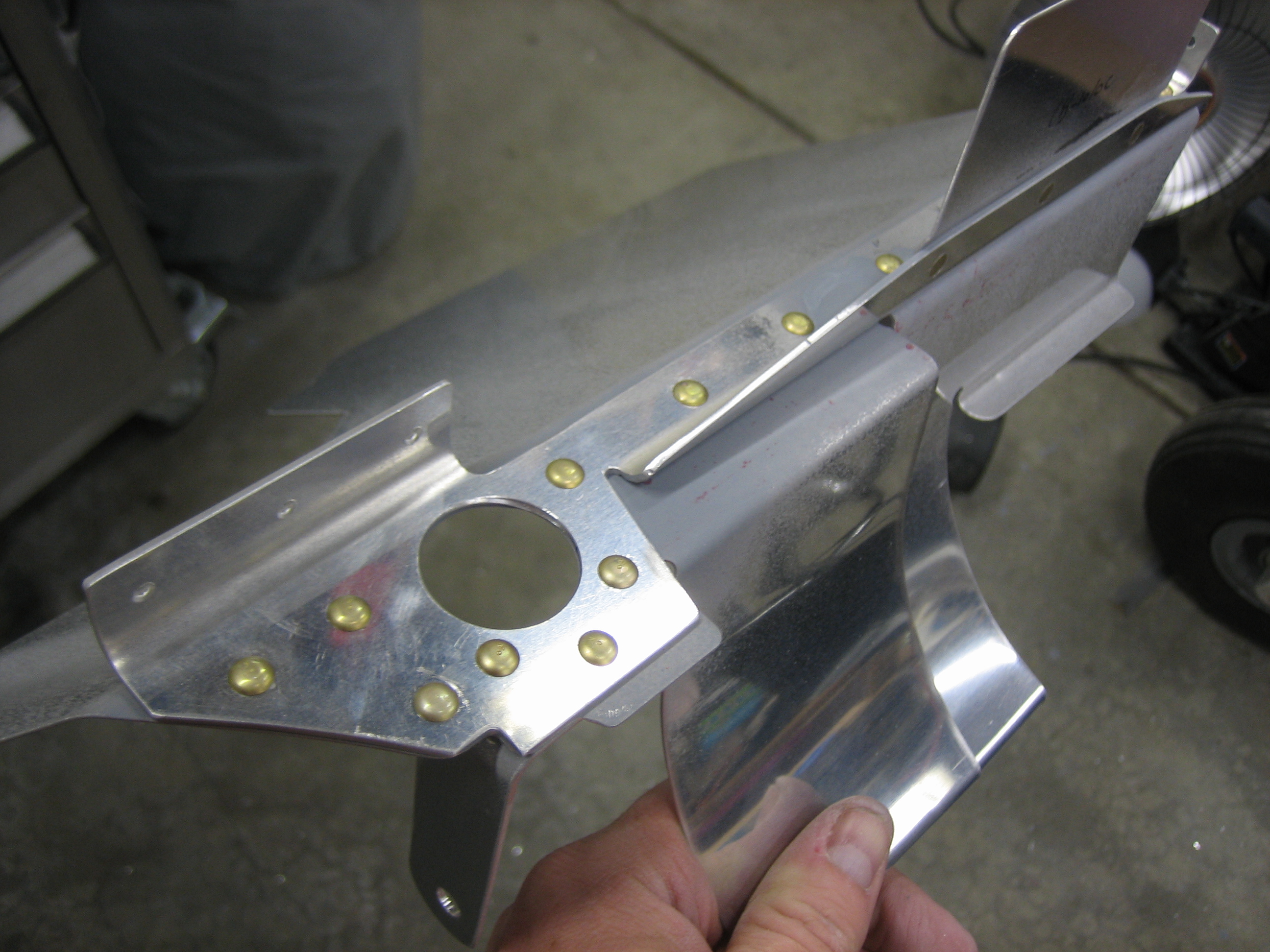
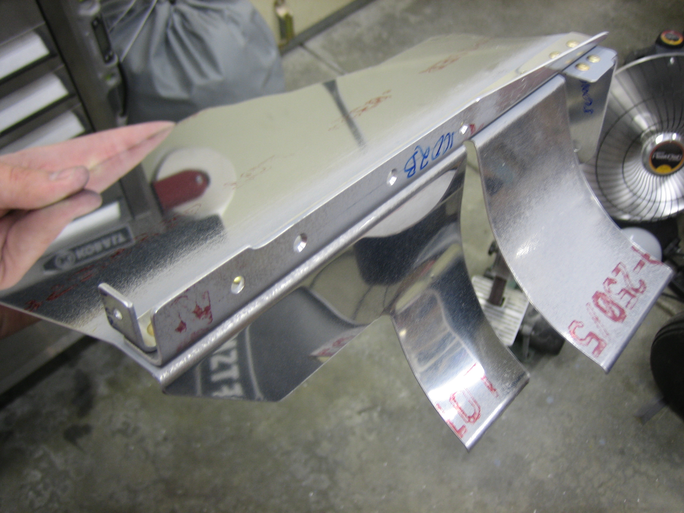
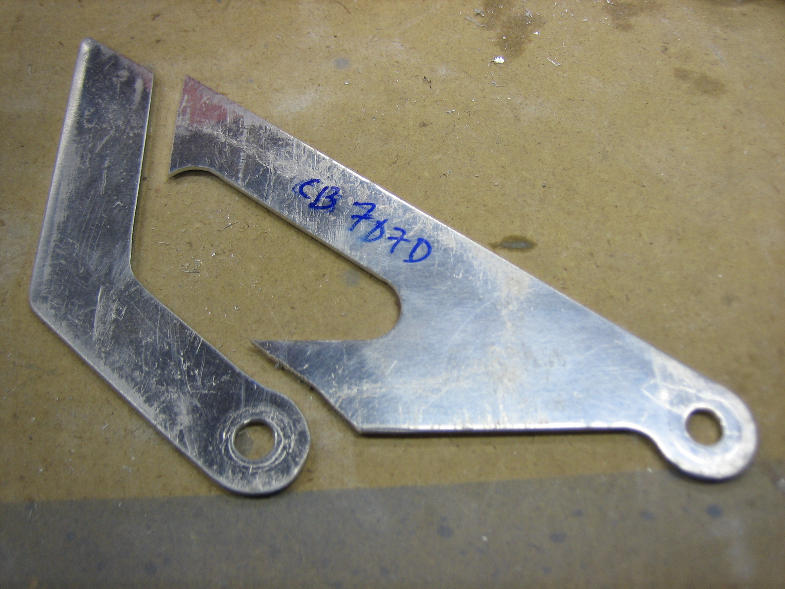
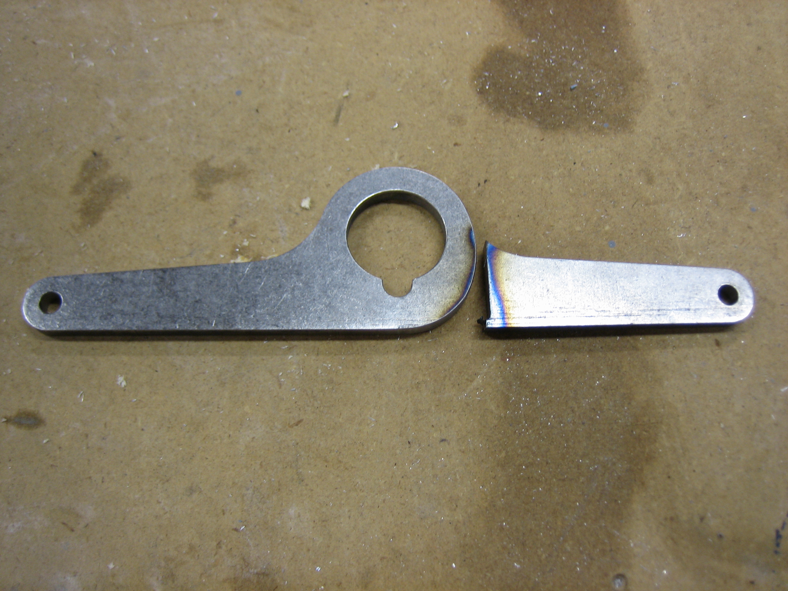
Since I’m going with the plenum, The rear baffle mount doesn’t need to be this large bracket since the upper edge of the aft wall will be supported by the plenum itself.  I cut off the forward end of this bracket.

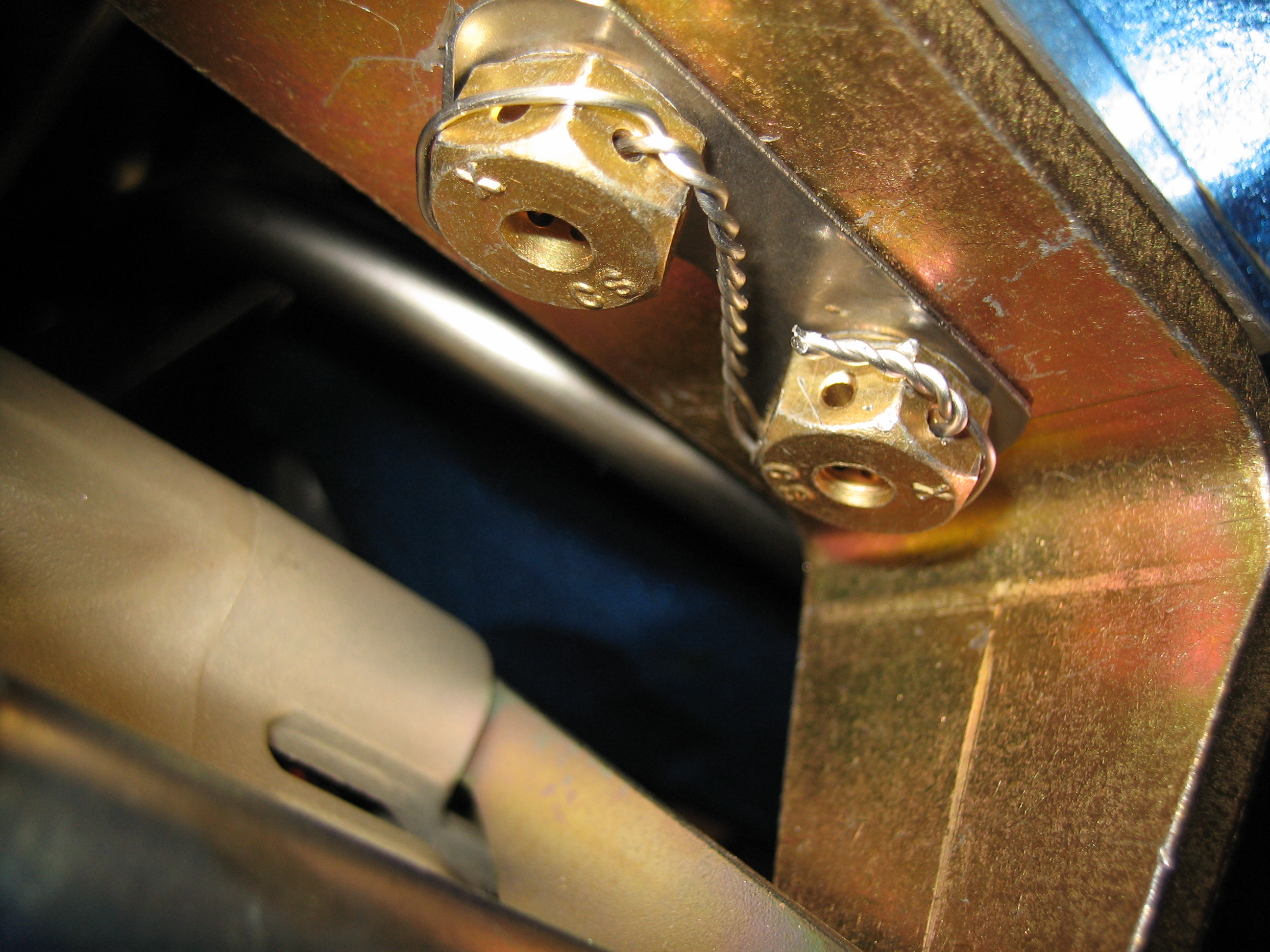
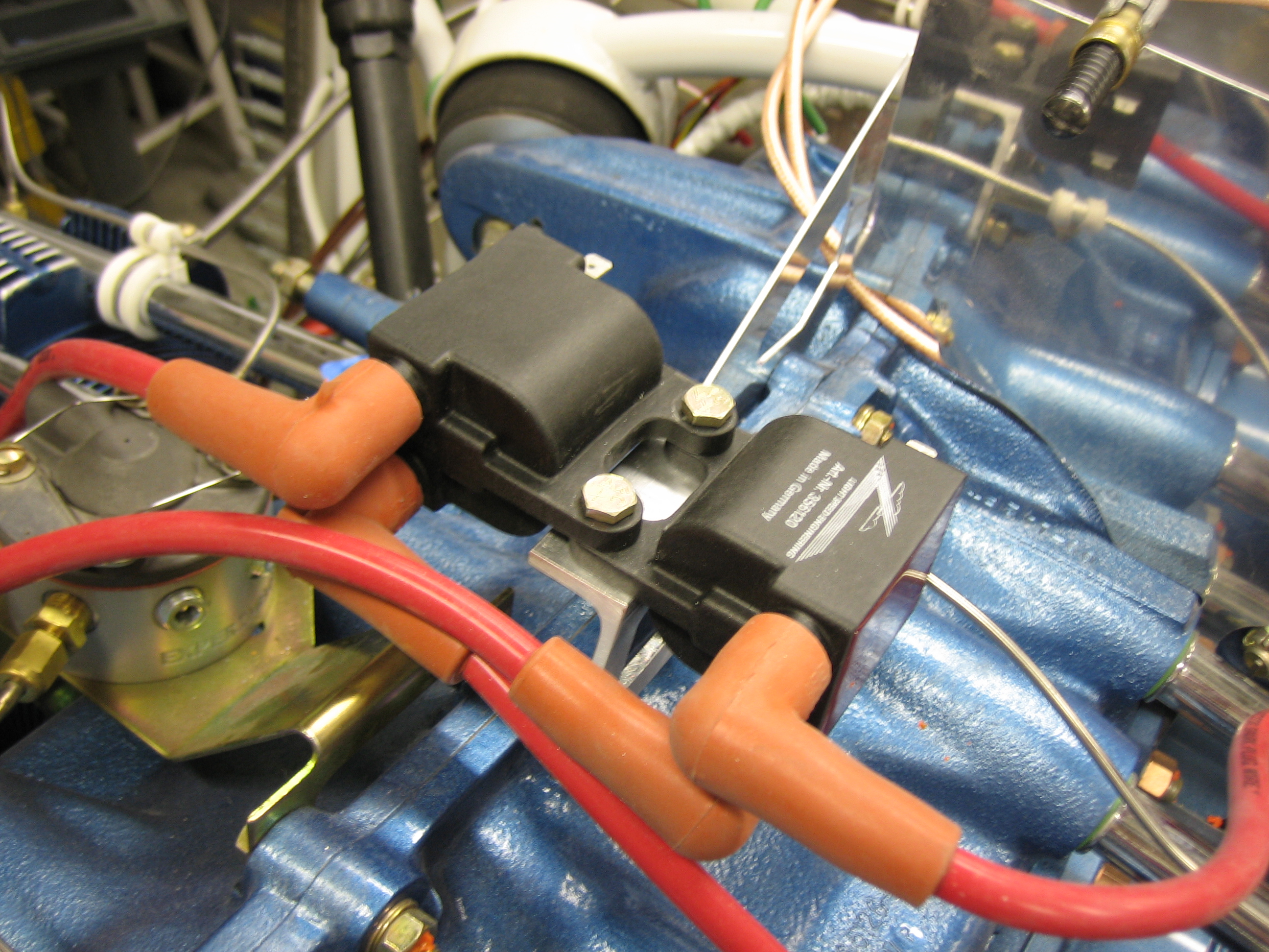
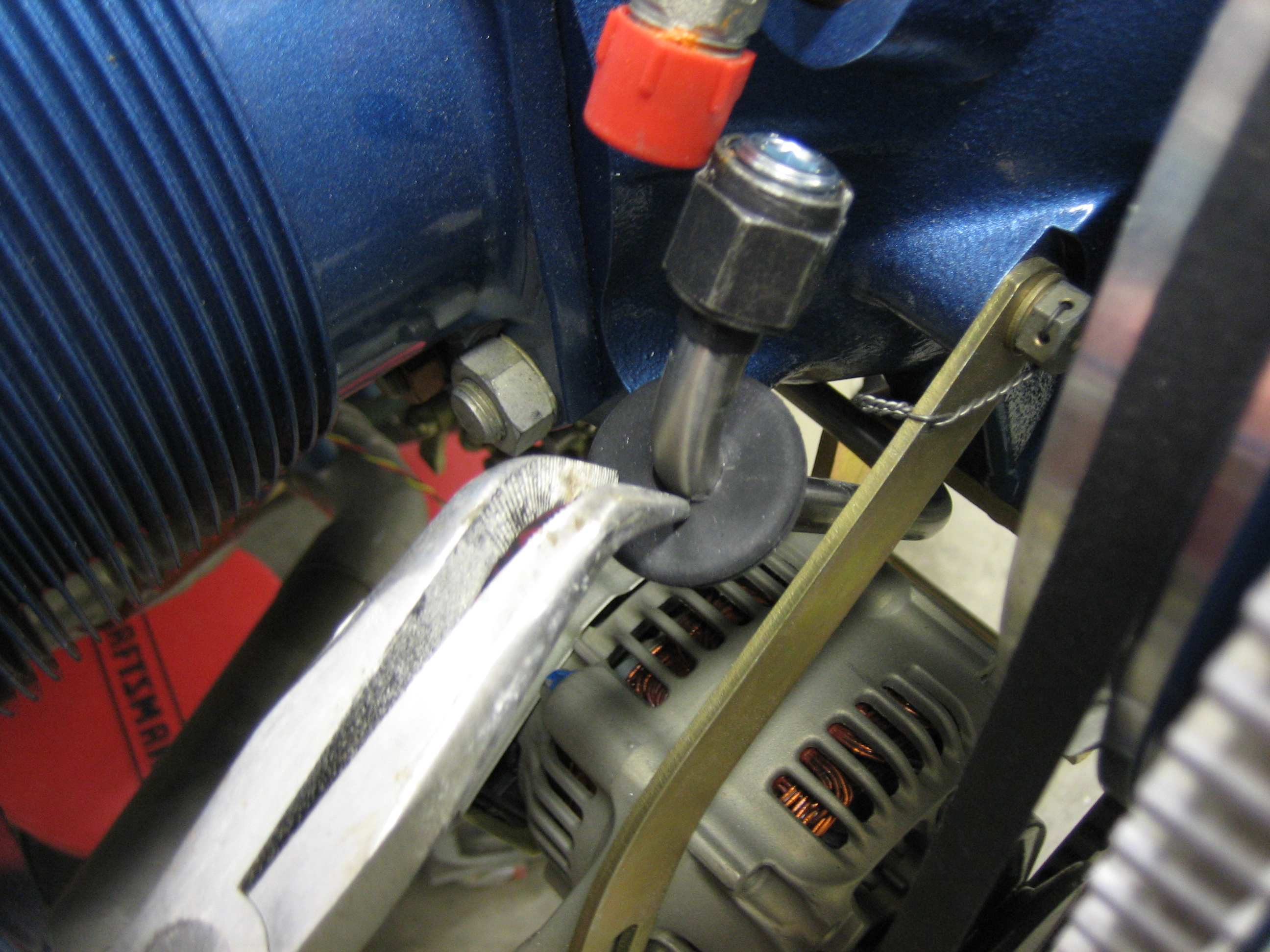
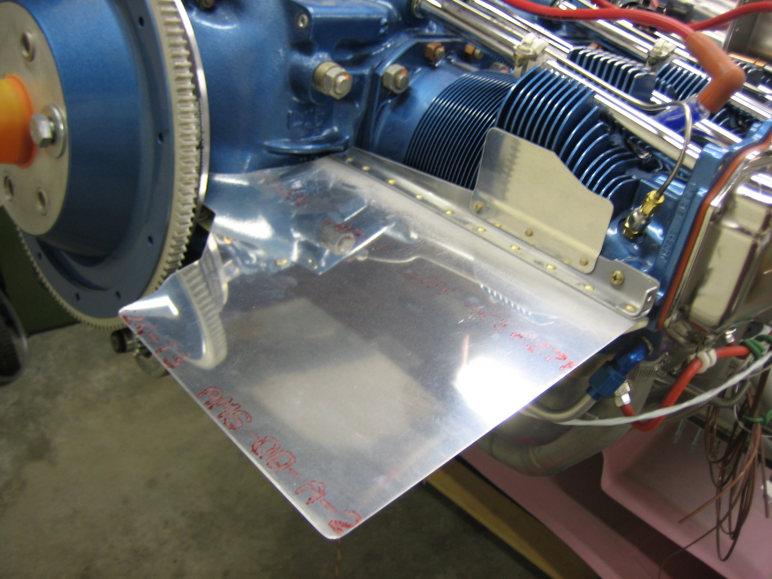
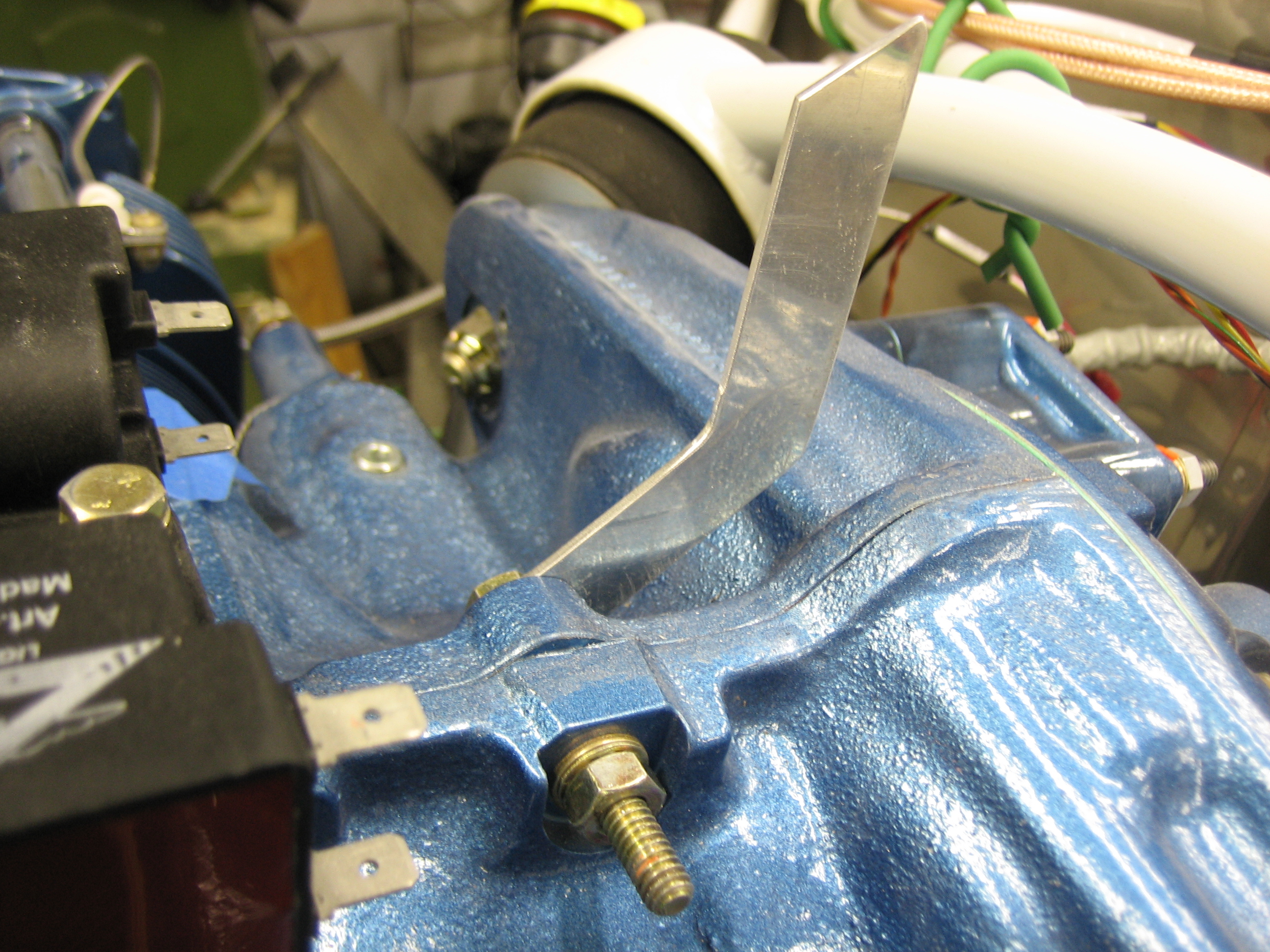
Here’s the bracket installed on the engine.  I really need to see if I can find a shorter bolt.  These 1/4″-20 case bolts are a little hard to find though.

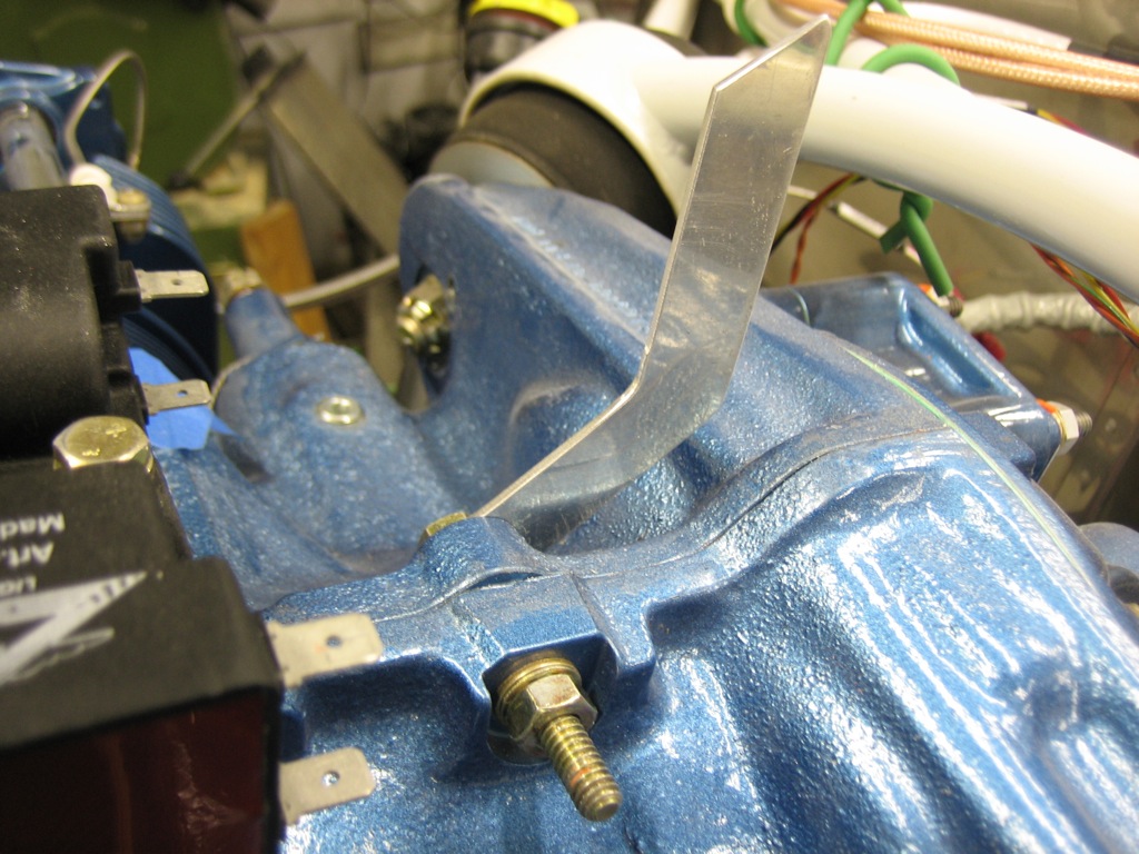
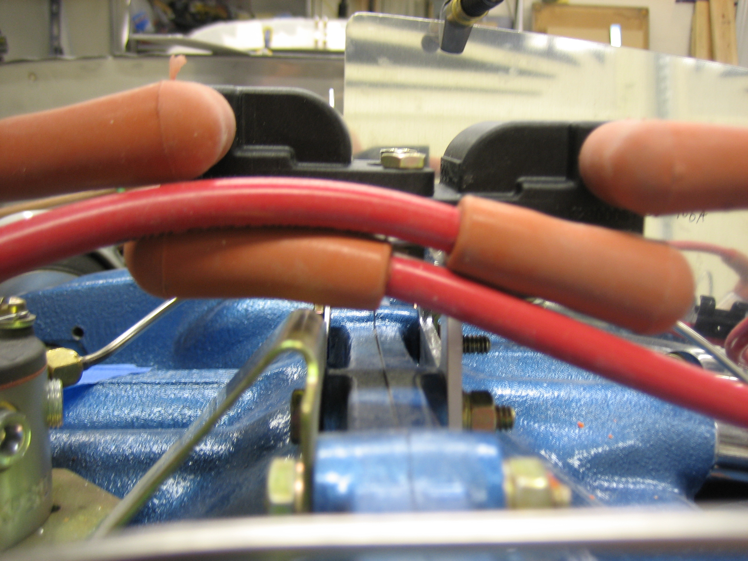
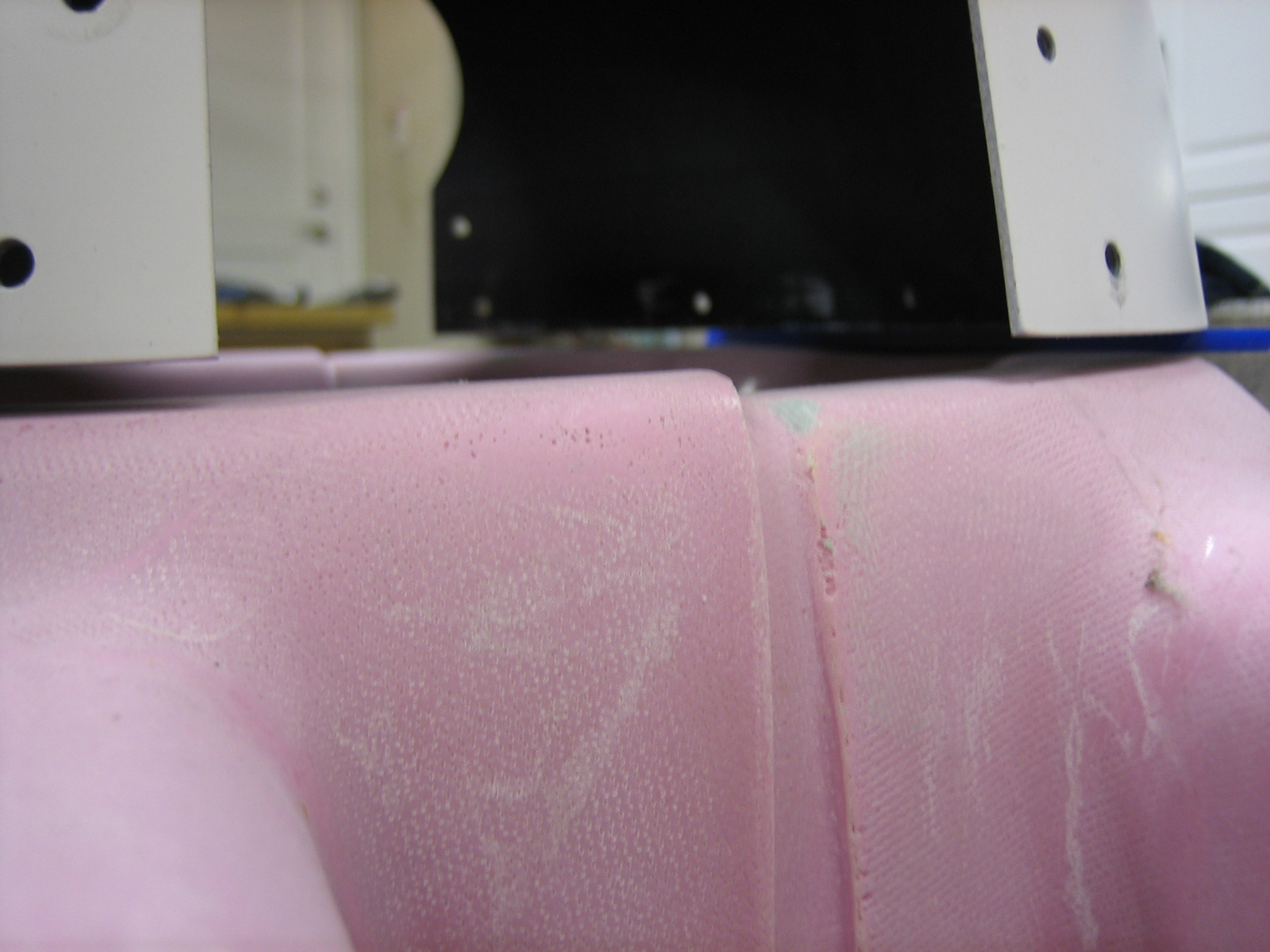
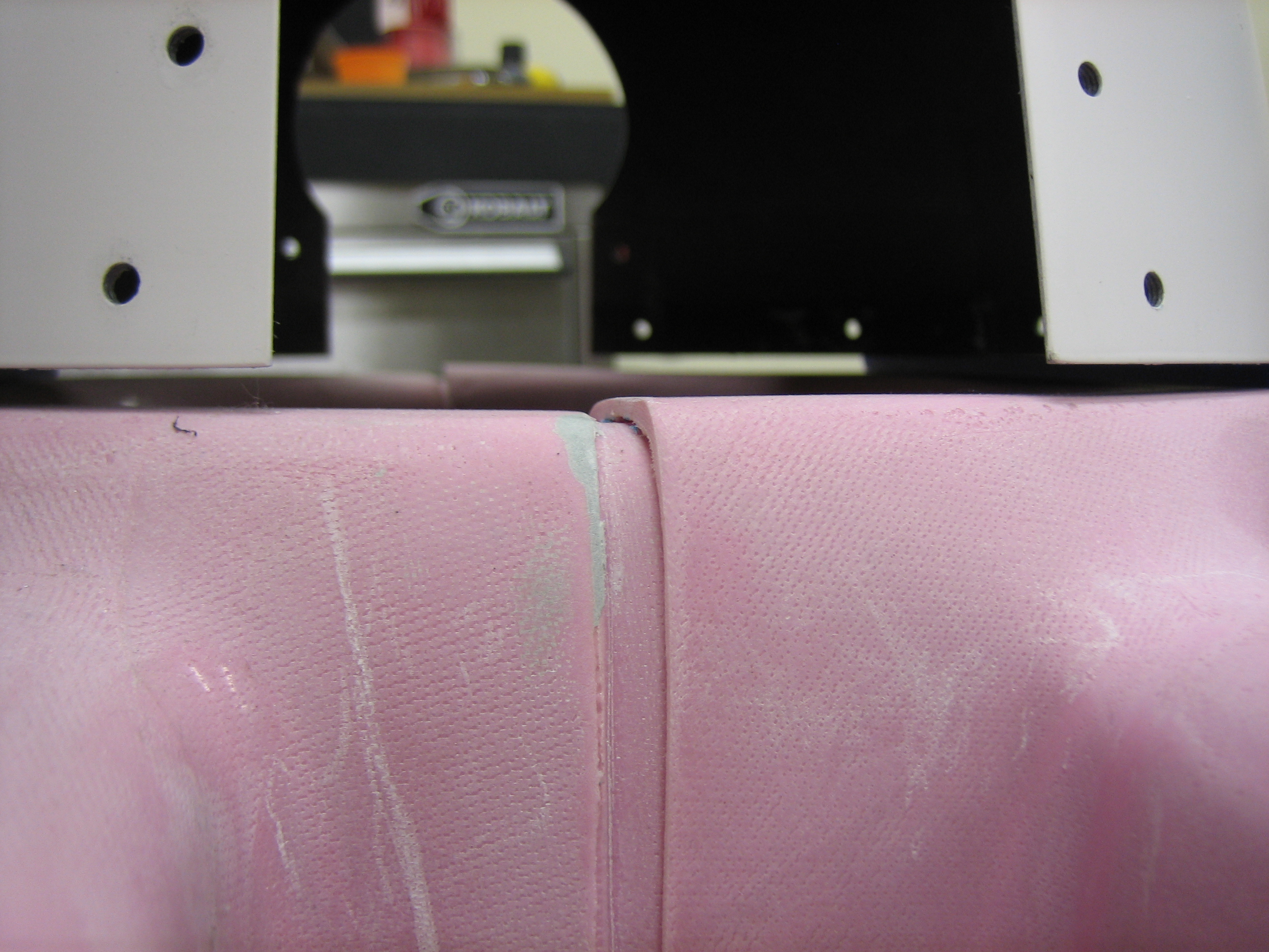
Now we have plenty of clearance.  There’s at least an inch above the coils now.  I’ll probably shoot for having the plenum sit about 1/2″ below the bottom of the cowl, so that should provide plenty of clearance between the coils and the plenum.  It’s less of an issue if the spacing between the coils and the plenum is tight though since the plenum will move with the engine.

Worked on Cowl and Spinner Fit

I was getting tired of having to squeeze under the engine to get from one side of the plane to the other, so I took the tailwheel spring off and tucked the tail up tight against the wall.

This gives me almost two feet between the spinner and the garage door; perfect.

While I had the tail spring off, I took the opportunity to get a bunch of the parts ready for powder coating.  Since I’m using the JD Air Parts tailwheel link which only attaches on one side, I sliced off the other arm from the tailwheel linkage and ground the part smooth.

I also stripped the primer from the Bell tailwheel fork so that it can be powder coated.  Afterward, I wrapped silicone tape around all surfaces of the tailwheel parts that I don’t want to be powder coated and set them aside.  The tailwheel spring is too big to fit in my little powder coating oven, so I’m going to see if I can drop by a friend’s place who has a pretty big powder coating oven and do them there.

I needed to get the joint at the front of the spinner adjusted so that the opening is circular.  Instead of measuring, I just put the spinner on the front of the cowl and adjusted the fit until everything lined up nicely.

I’m using 1/8″ spacers between the cowl and the spinner.  The gap is surprisingly good along the top.

However, the joint between the top and bottom leaves a lot to be desired.

The left side is a little better, but there’s still a noticeable step.  I spent a little time working on the fit, but there is still a lot to do before this will look good.  I’ll probably end up making the gap between the cowl and spinner a little larger to start with and I can tighten it up with some fiberglass layups at the same time I’m fixing the fit between the top and bottom halves.

I spent the rest of the night digesting the instructions and plans for the cowl.  This is likely going to be one of the tricker parts of the build.