Wired Remaining EGT and CHT Probes

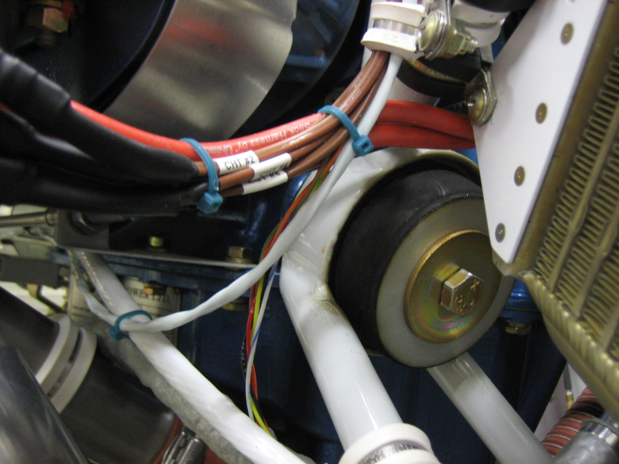
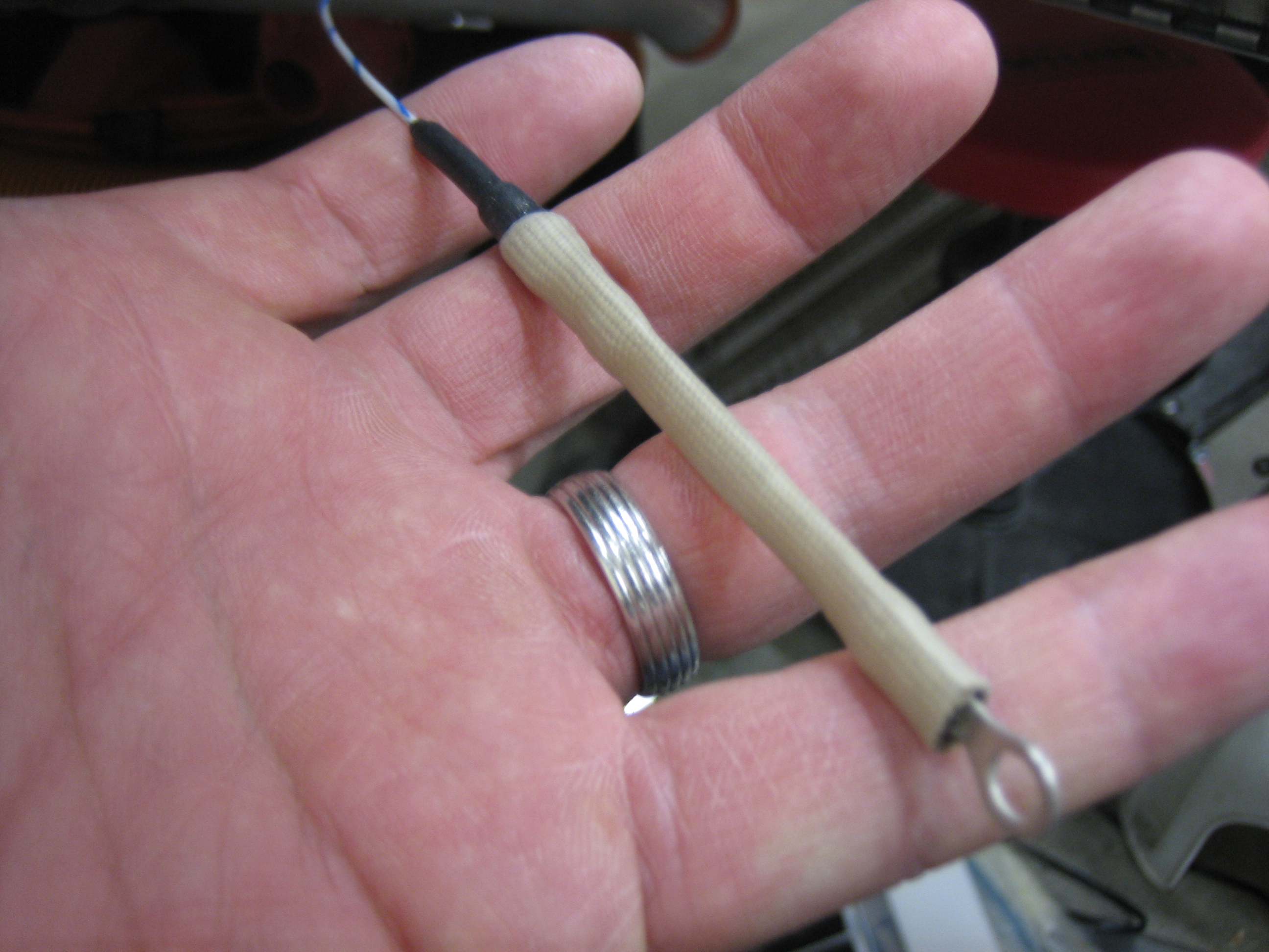
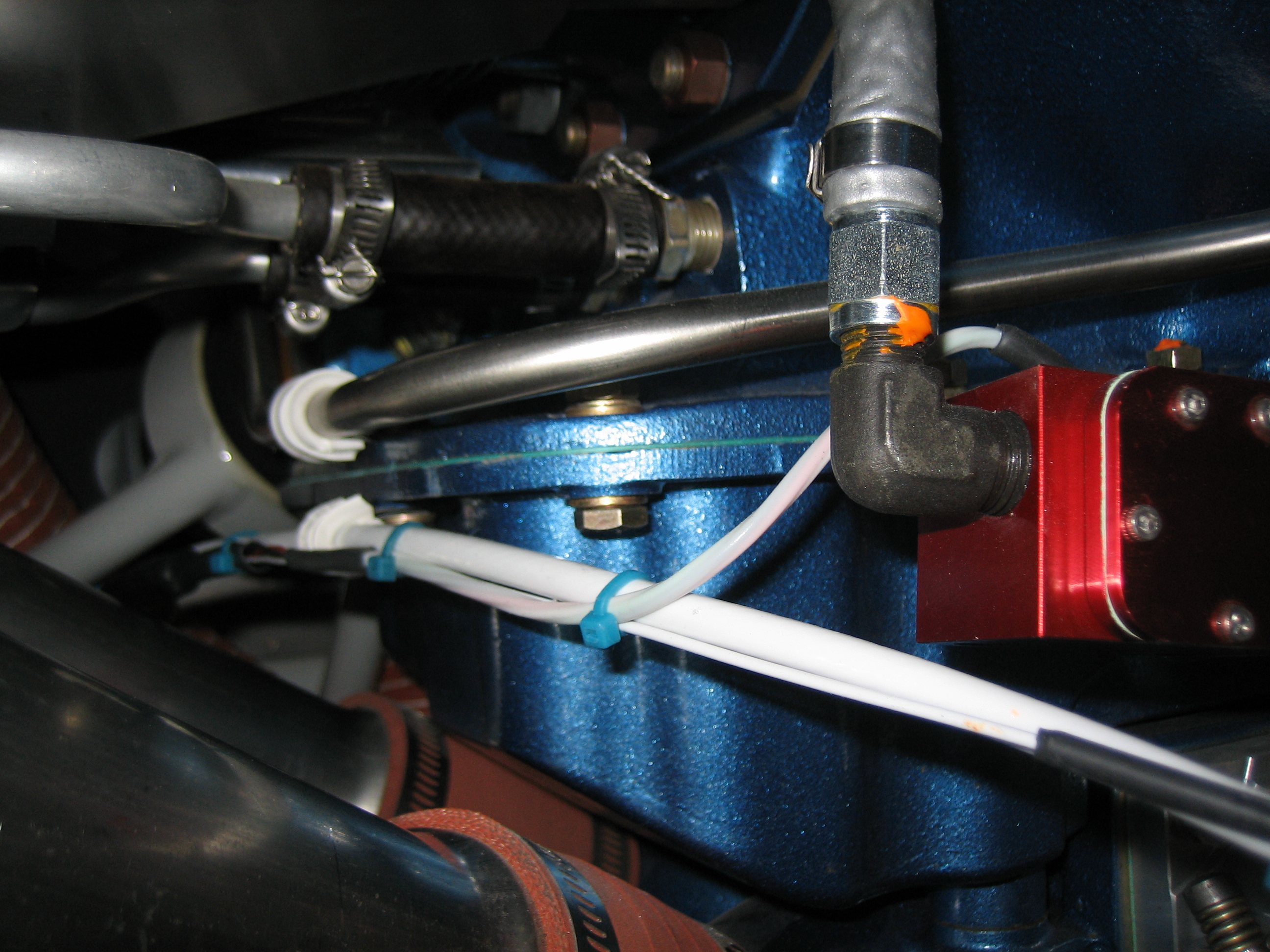
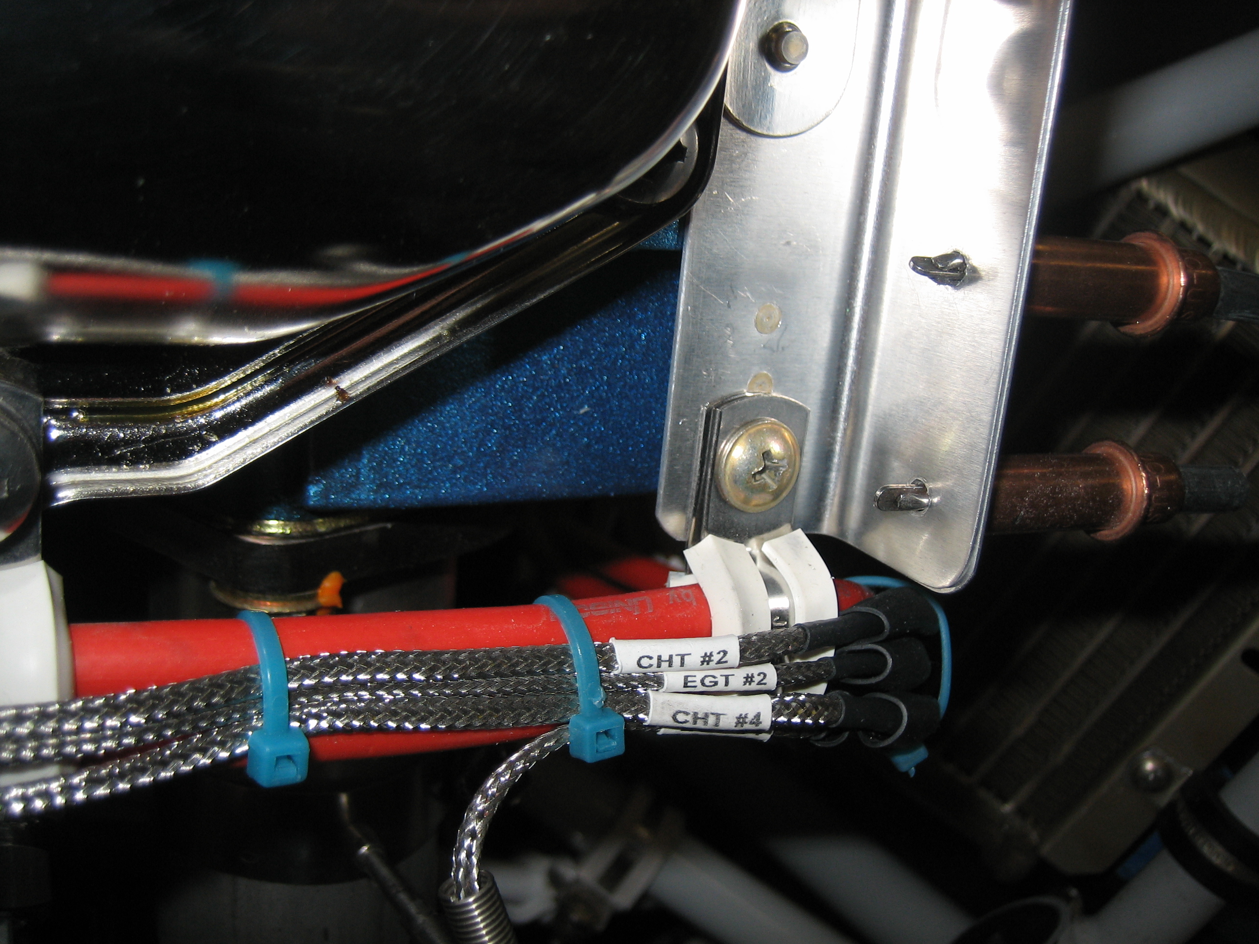
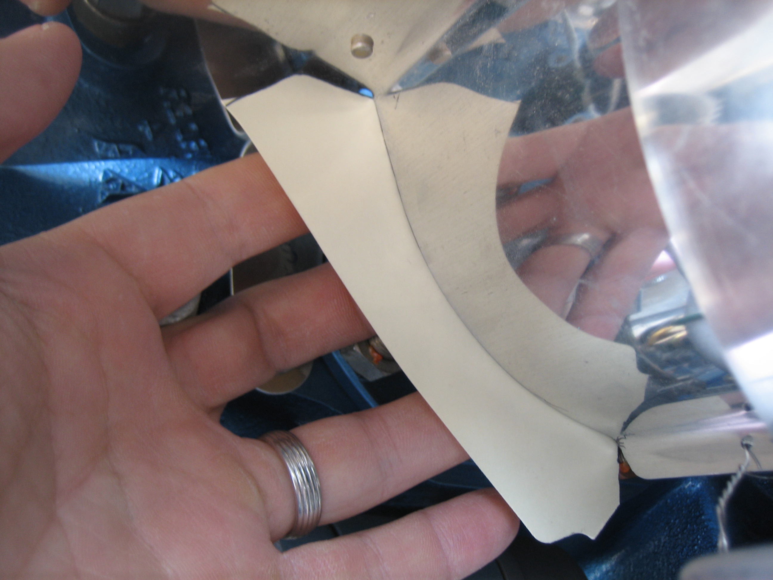
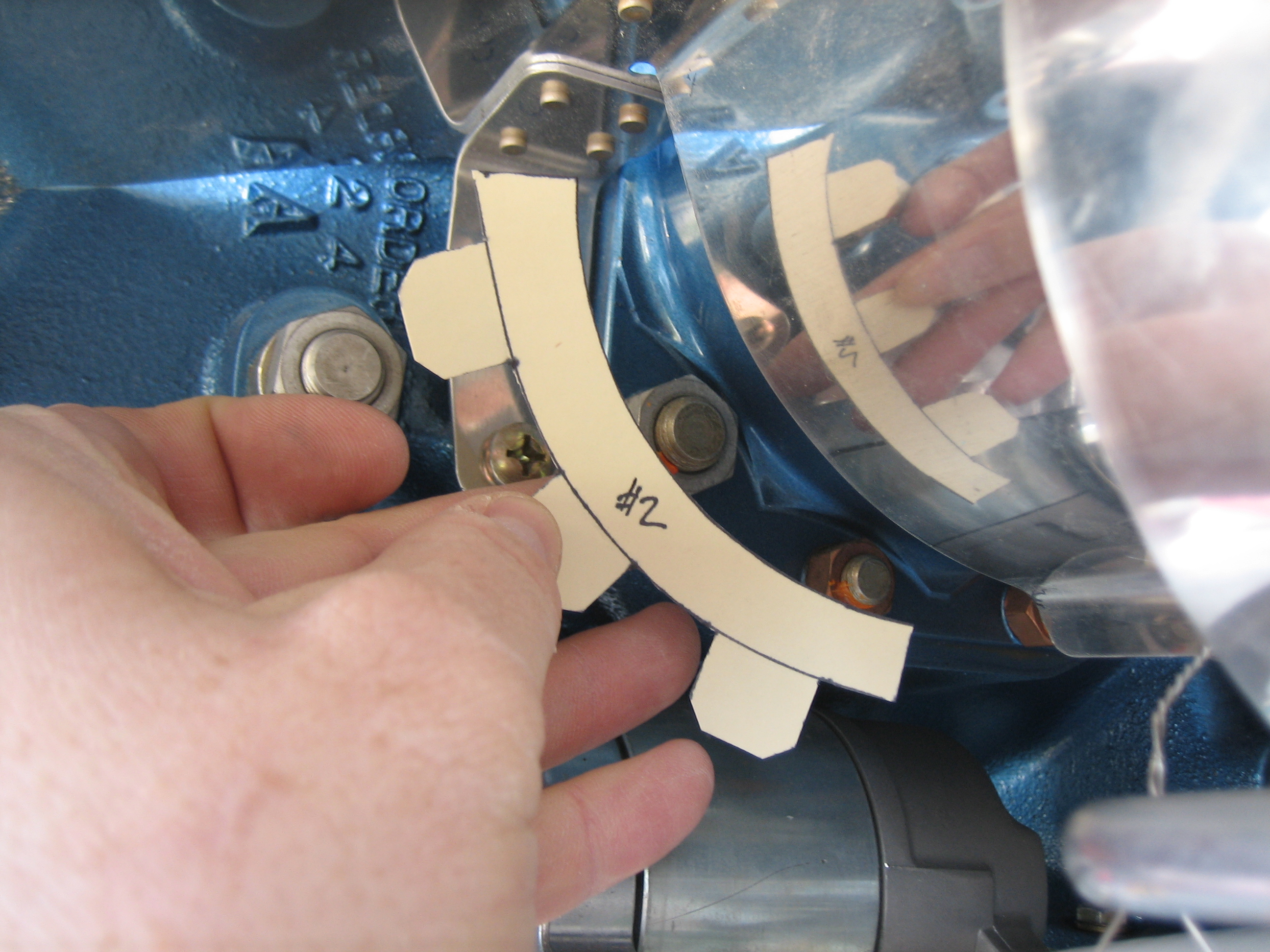
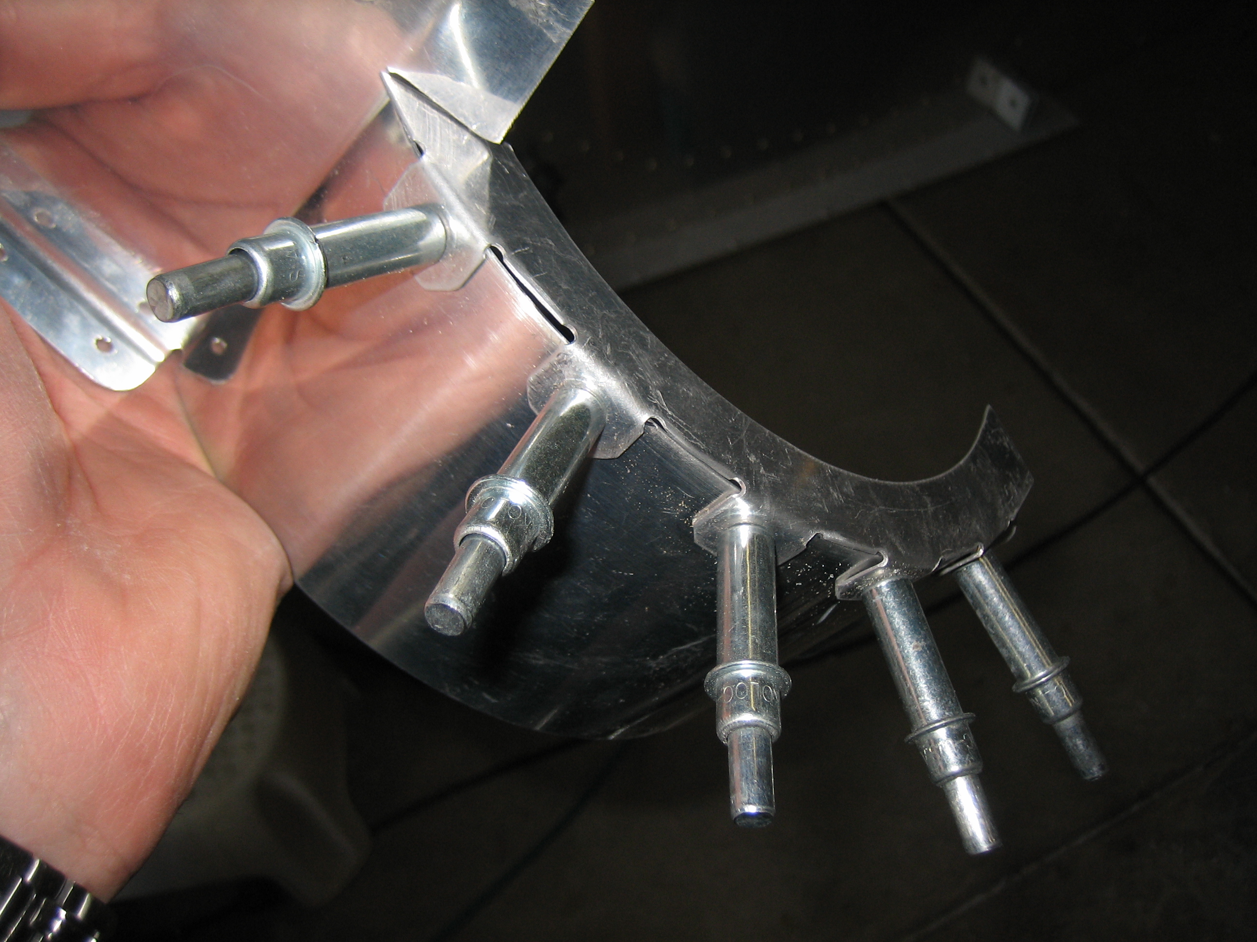
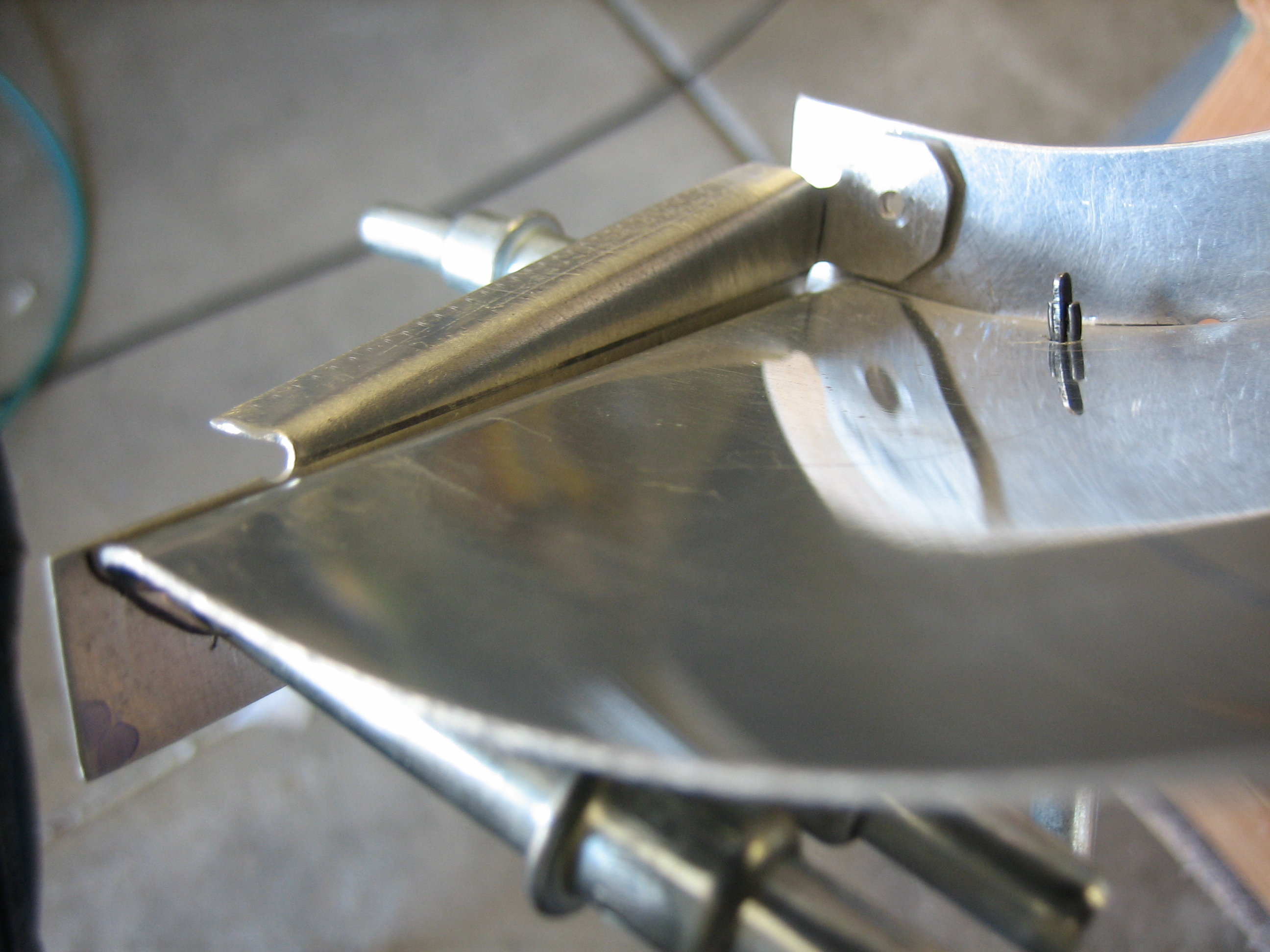
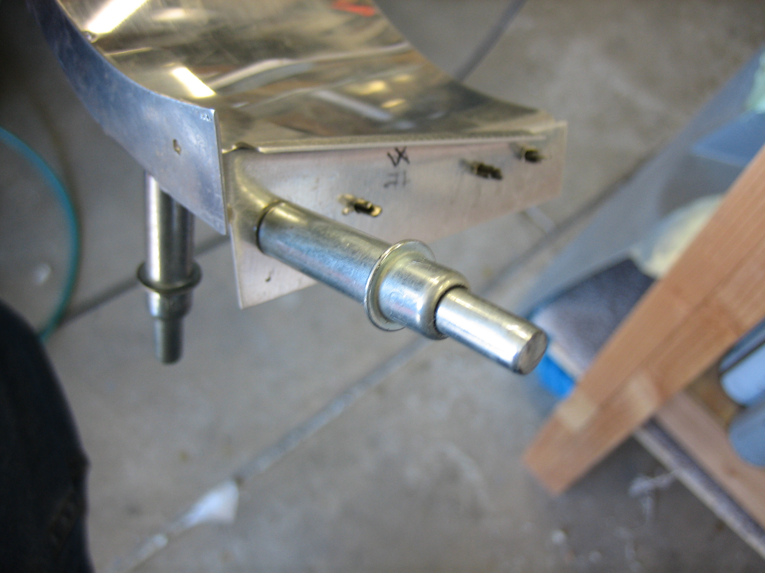
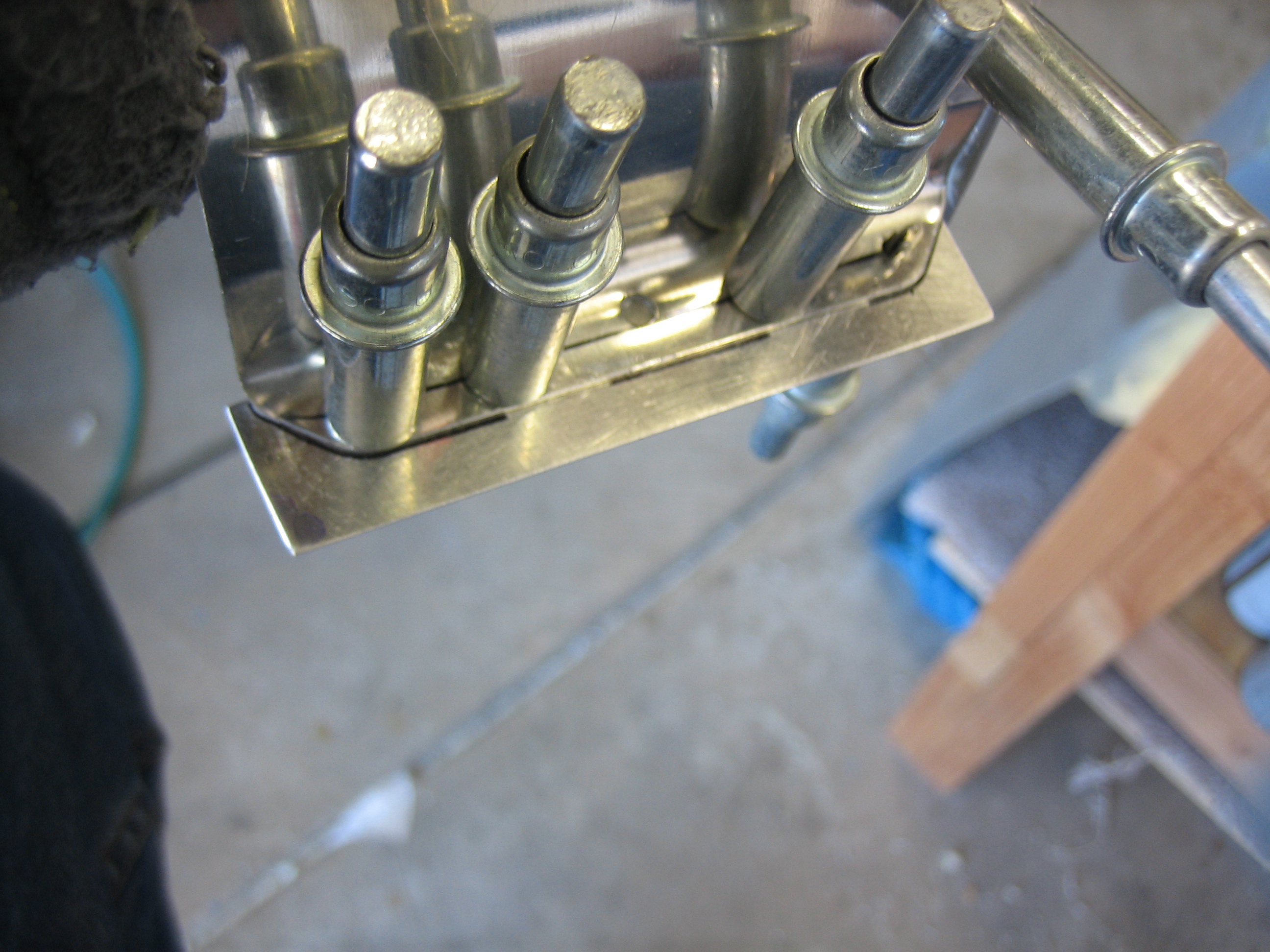
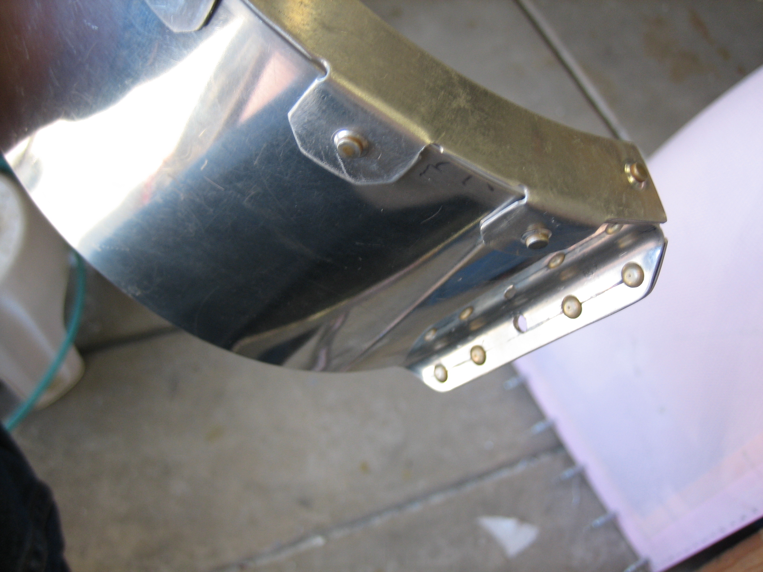
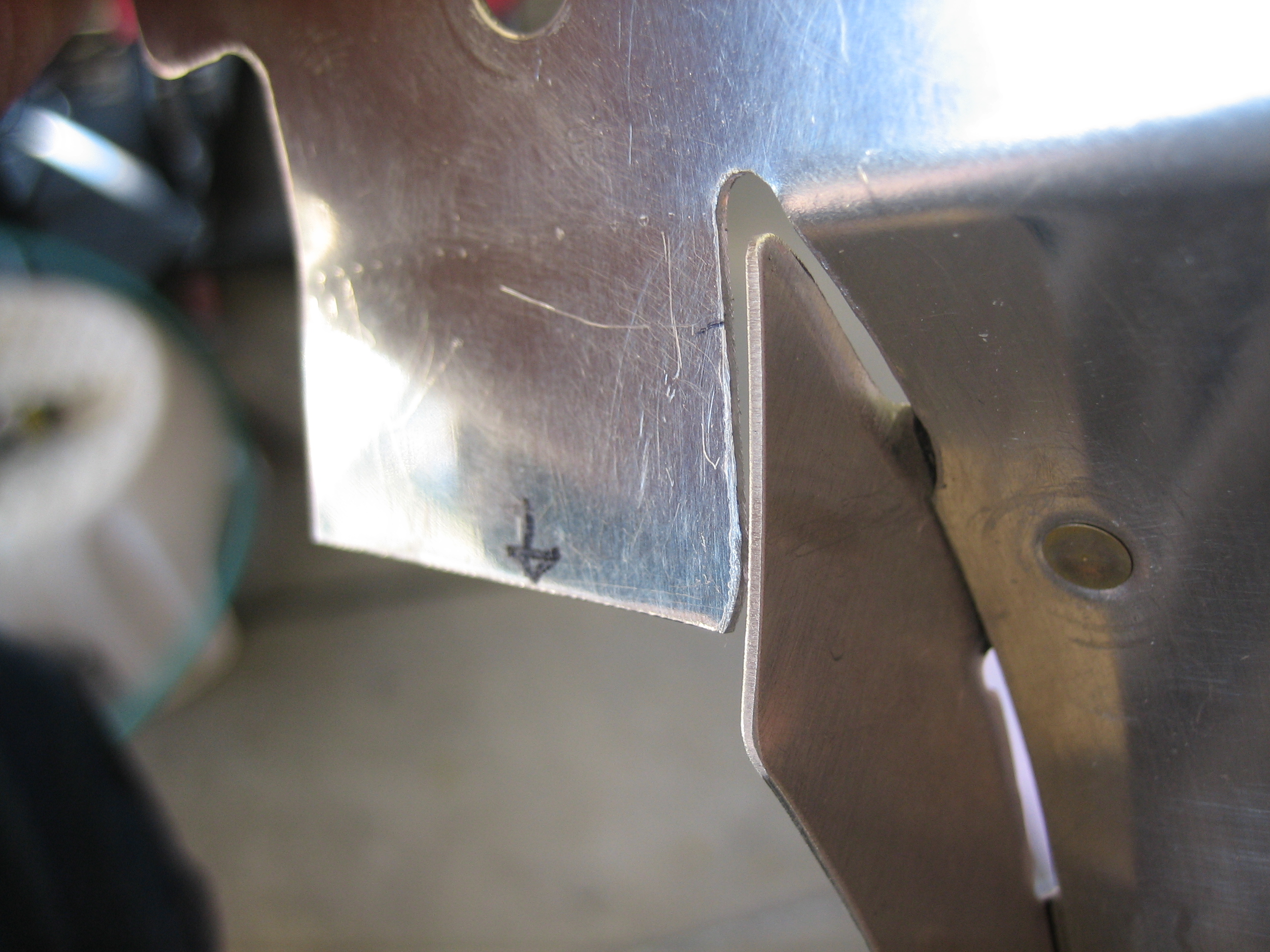
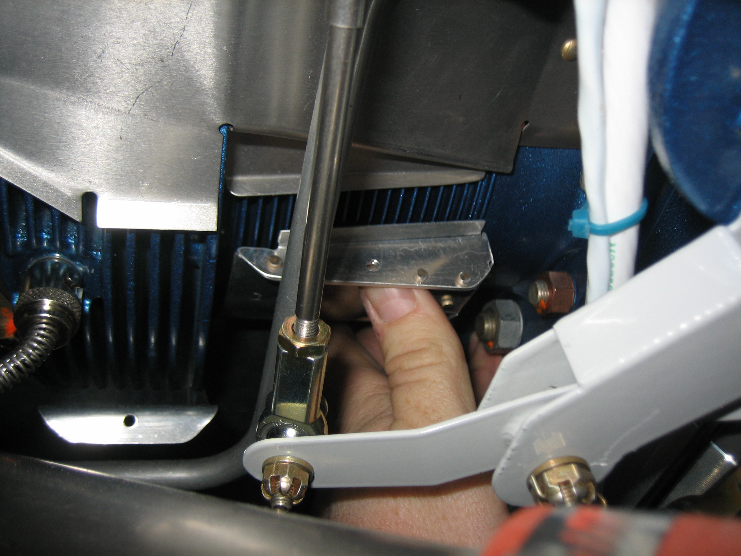
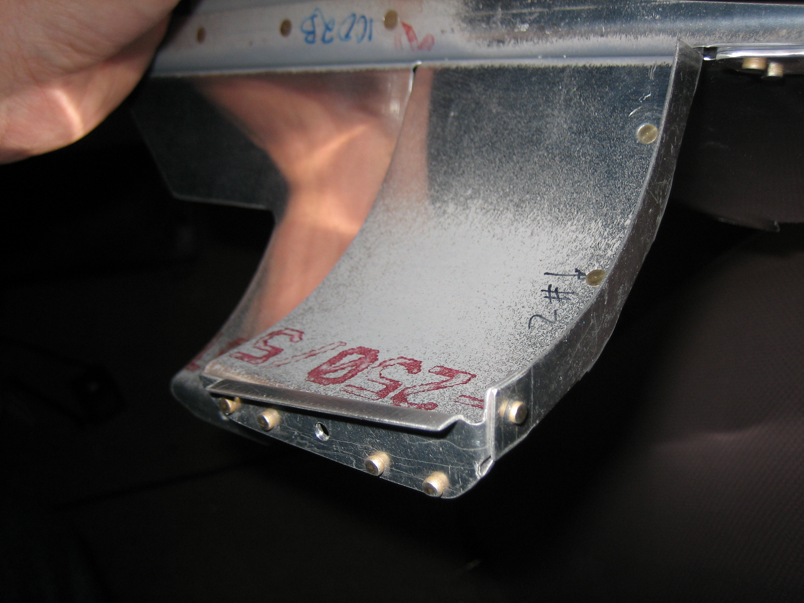
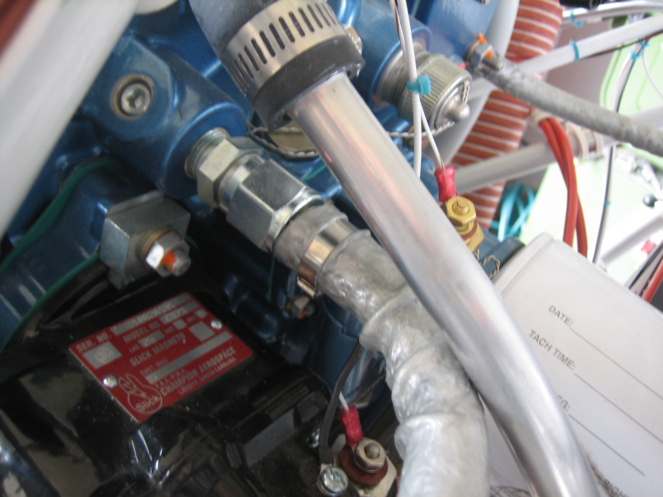
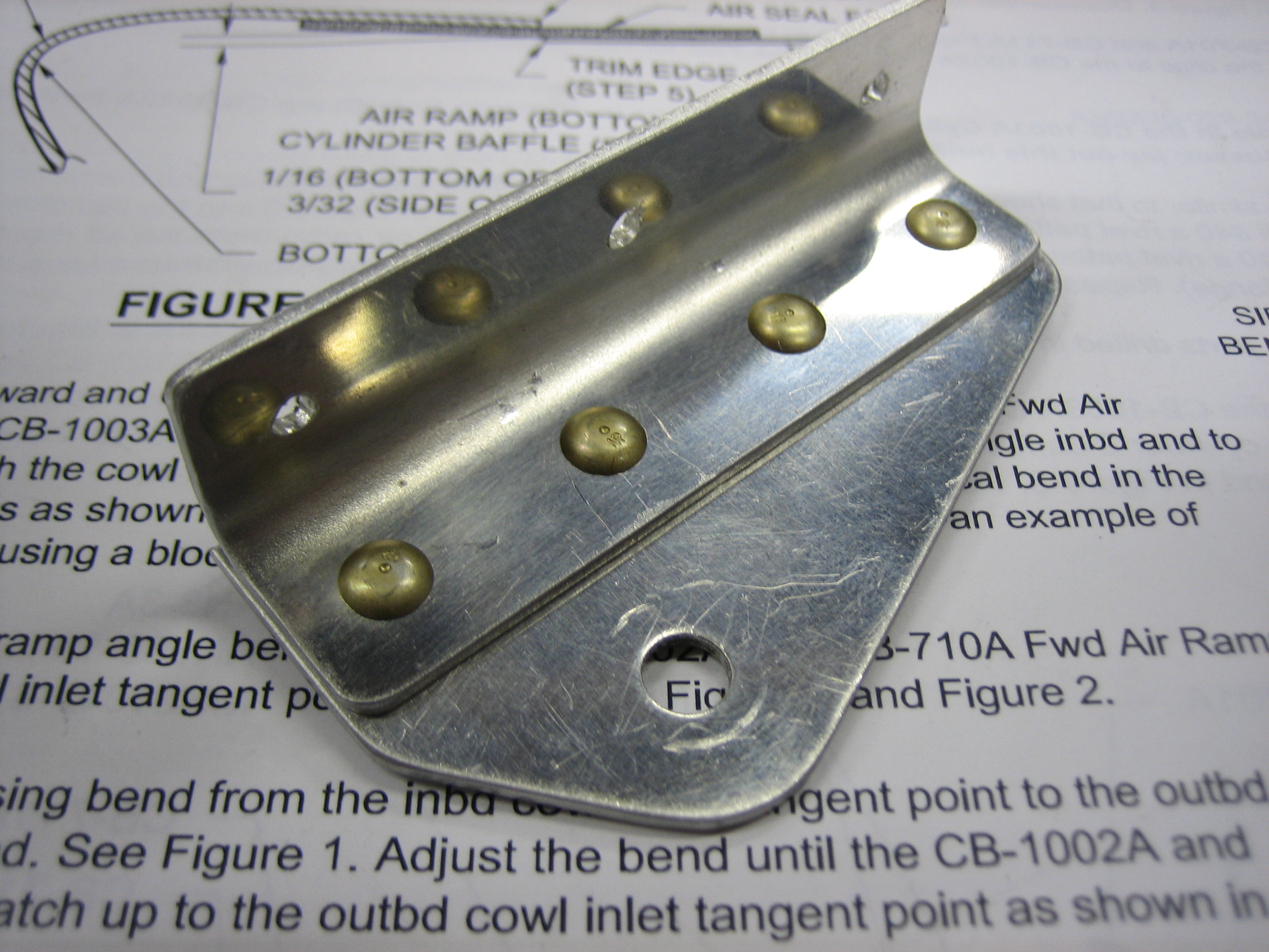
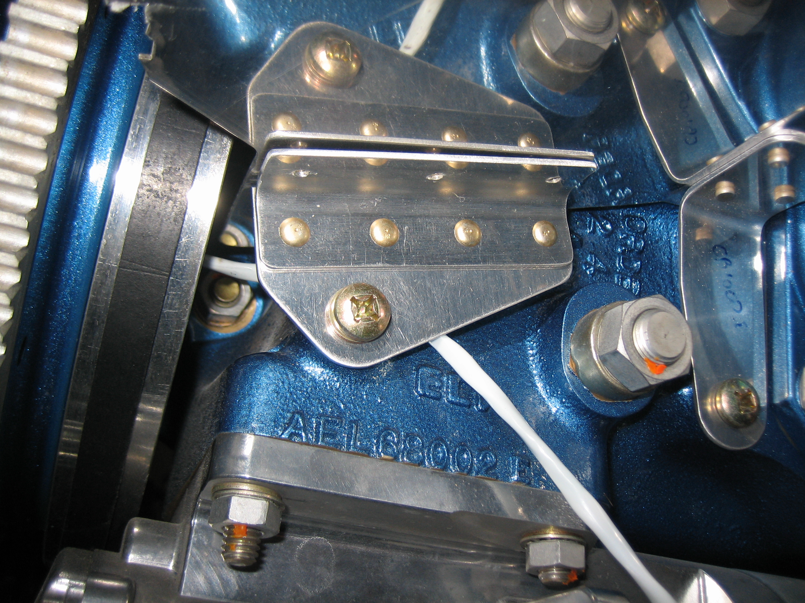
With the final location of the oil cooler and ducting determined, I could finish wiring the EGT and CHT probes.  I decided to run the wires inside of the oil cooler ducting since they could be better supported by the engine mount.  I trimmed the wires to length and added knife connectors.  These are covered by the heat shrink in the lower left.  The wires are secured in a couple of spots along the engine mount with adel clamps along with the ignition sensor, fuel flow, ammeter shunt and starter contactor sense wires.

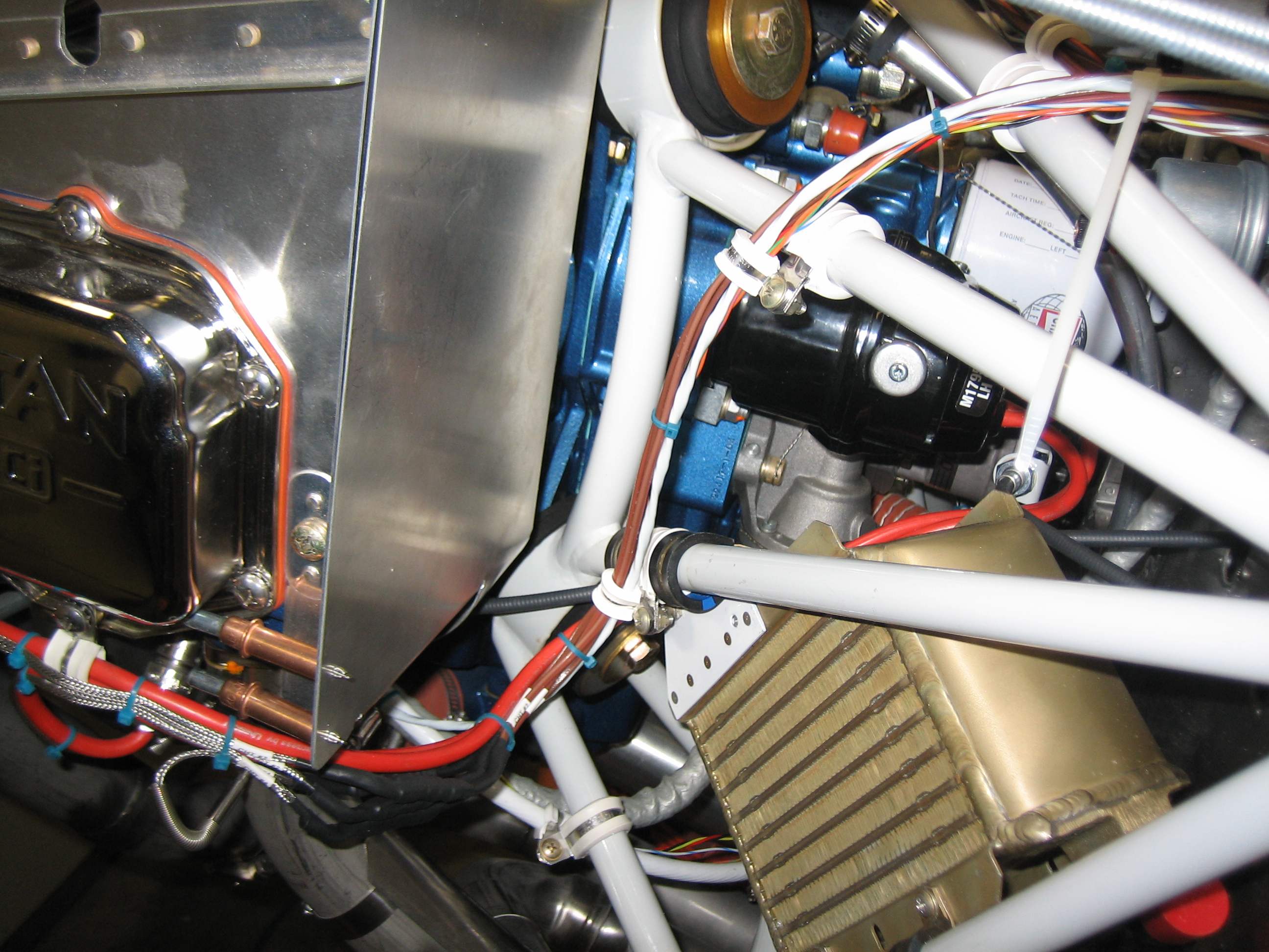
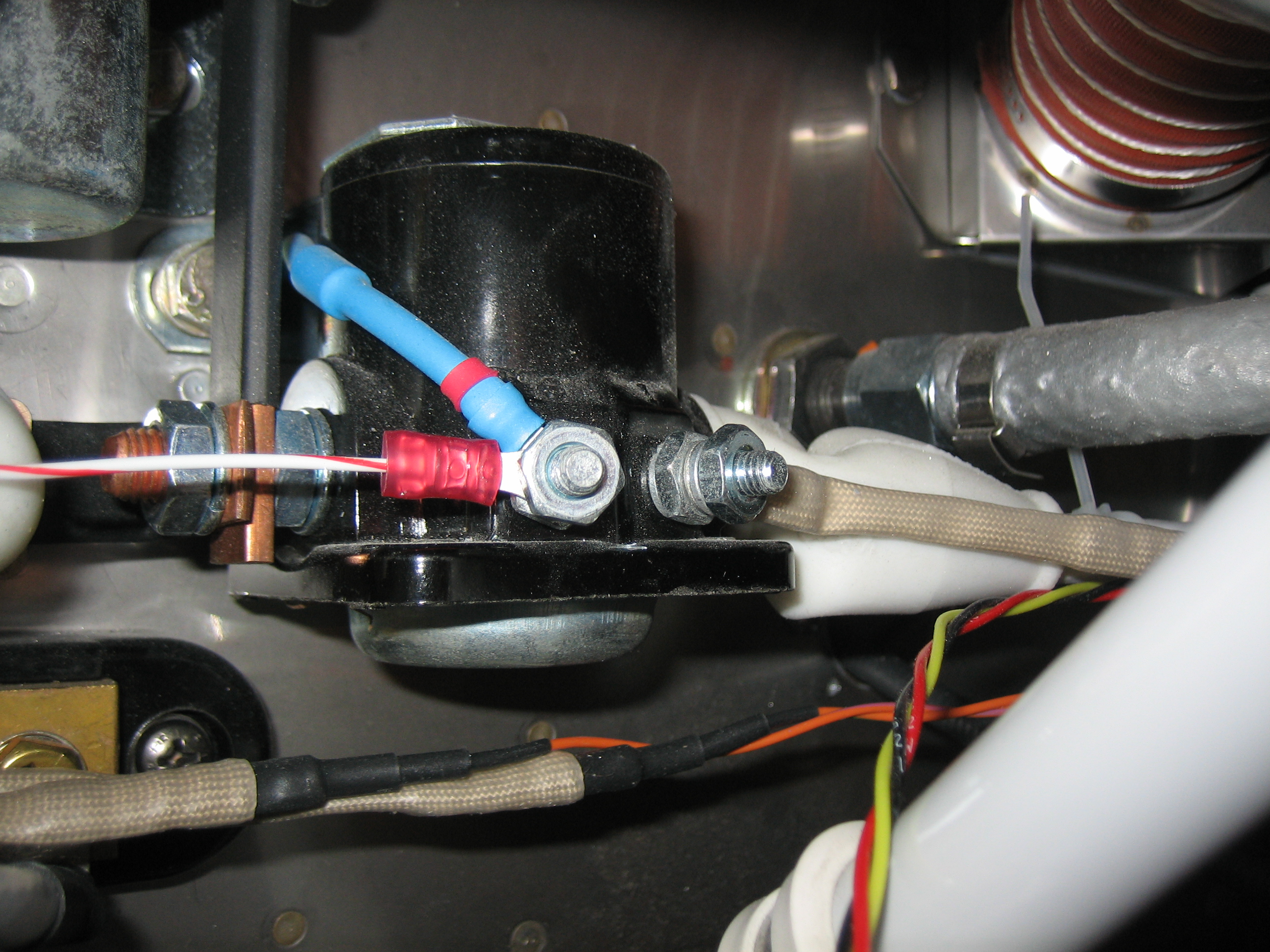
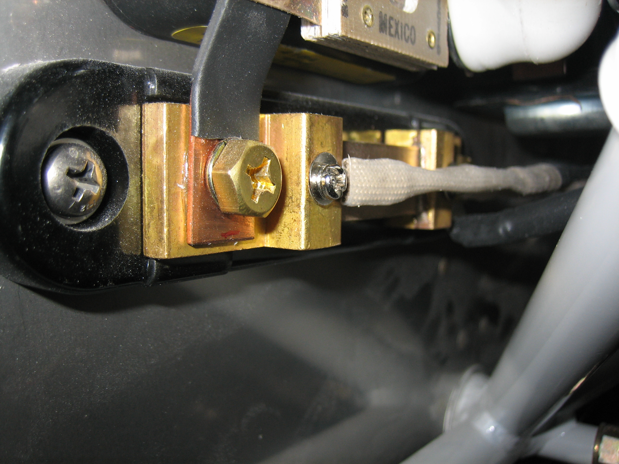
Where the wires exit the lower adel clamp, the EGT/CHT wires turn left and follow the lower ignition wires.  The ignition sensor wire follows the starter wire forward and the other sense wires follow the starter wire aft.  Now that the final position of these wires has been determined, I can finally hook up the other ends to the various devices.

Wired Starter Sense and Alternator Shunt Sense

I fabricated several 26AWG fusible links for the sense wires connected to the starter contactor and alternator shunt.  Here’s the one for the starter contactor.

This attaches to the right post on the starter contactor so that the VP-X knows when the starter is engaged.  You can see the two additional fusible links below the starter contactor.  These connect to the shunt.

Here’s where these fusible links attach to the shunt.  Before connecting these wires to the shunt, I attached the battery charger to the alternator side of the shunt to determine the correct orientation.  Attaching the two sense wires to the wrong sides of the shunt would result in a negative current indication from the alternator.  If I didn’t determine the correct orientation now and got it backward, it would require reversing the sense wires at the EMS end which would be challenging once for the forward fuselage skin is riveted on.

Finished Fuel Flow Sensor Wiring and Secured Wiring Runs

I finished up the fuel flow sensor wiring run by crimping knife connectors on the wires from the EMS and attaching them to the wires from the FT-60 (red cube).  I covered each of the knife connectors and the whole bundle of connectors with some heat shrink tubing and secured the wires with some Tefzel zip-ties.

The bundle of ignition, EGT and CHT wires running aft from the #4 cylinder weren’t well supported.  I riveted a K2000-3 nutplate to the side baffle and used a two-wire adel clamp to secure the bundle to the baffles.  This prevents these wires from flexing down and contacting the #4 exhaust pipe (or flexing up and contacting the baffles under negative G conditions).  Other than hooking up the starter wire just before first engine start and the coax wires to the electronic ignition coils, I believe all of the firewall forward wiring is complete.  Other than final hookups of wing and empennage components (lights, roll servo, OAT probe, etc.), I believe all of the firewall aft wiring is complete as well.

Continued Trimming Baffles

No pictures today, but I resumed trimming the baffles.  This was an iterative process that involved using paper clips along the top edge.  They’re pushed down when the top cowl is installed.  You can then measure down from the top of the paper clip a bit to determine where to cut.  The plans specify to trim the baffles to clear the top cowl by 3/8″-1/2″.  Since I’m installing a plenum, I went to 1/2″ since the plenum will stick up 1/8″ or so.

Finished Trimming Baffles

I finished trimming the baffles to clear the top cowl by 1/2″.  I’ll still probably have to trim them a little more to follow the shape of the plenum since I’m fabricating that on a mold that I didn’t make.

Afterward, I fabricated a couple of these little clips that keep the forward and aft cylinder baffles tight together while still allowing them to move independently.

Started Working on Modifying Baffles for ECI Tapered Cylinders

My engine uses cylinders from ECI that have tapered barrel fins.  This saves between 5-6 lbs of weight, but complicates the baffle installation.  The premade baffles are designed for non-tapered barrel fins, so they have to be modified to seal properly.  ECI provides a template for building a filler piece to close off the tapered end and to fill the wedge-shaped gap along the bottom.  I didn’t like their template for a couple of reasons, so I decided to just make my own.  First up, I used some safety wire to pull the inner baffles tight against the cylinder barrels without twisting them.

I then used a piece of manila file folder to trace the shape of the inner edge of the baffles.

After adding some ears and cutting it out, here’s the template for the #2 cylinder.  I then repeated the process for the other three cylinders.

After transferring the templates to some 0.032″ 2024-T3 aluminum sheet, I cut them out.  Here’s the #4 cylinder filler piece clecoed in place.

You can see that the ears are bent around the outside edge of the baffles.

More Progress Modifying Baffles for ECI Tapered Cylinders

Where the baffles end, a tapered shim needs to be fabricated so that the baffles seal tight against the fins.  This forces all of the cooling air to go between the fins instead of around them.

This shim will be riveted to the flange on the end of the curved portion of the baffles.

I left the new piece long while fitting it.  I’ll trim it off flush with the existing flange now that the holes are drilled and its position is fixed.

Here’s what it looks like with everything riveted together.

From the other side, you can see the ears of the side piece and the rivet that ties it to the tapered shim.

The modifications for cylinders 1-3 are pretty much the same.  The modification for cylinder #4 is quite a bit different.  It wraps much farther around the cylinder and the width of this side piece gets larger near the top.  I trimmed it to roughly follow the ear that rests above one of the cylinder mounting nuts.  All of the gaps will be filled with high-temp RTV silicone.

This picture gives you an idea how the shim follows the taper of the barrel fins.

Here’s the completed #2 cylinder baffle mod.  I still have the #1 and #3 cylinders to do, but that will have to wait until tomorrow.

Installed Remaining Firewall-Forward Hoses and Finish Baffle Modifications for ECI Tapered Cylinders

My hopefully final hose order arrived from Bonaco today.  First up is the upper hose to the oil cooler.  This comes straight off the back of the engine above the left mag.  I’ll add a couple of adel clamps to tie the oil hose to the breather tube.  This will keep the hose from rubbing against the breather tube as well as stabilize the breather tube a bit better.

That hose runs just inside the forward engine mount tubes and connects to the upper oil cooler port.  I’ll add another adel clamp here to secure the oil hose to the engine mount.

The lower oil cooler hose routes around the back of the oil cooler and then connects to the 45º angle fitting above the propeller governor.  I’ll cut a relief in the oil cooler flange to keep this from abrading against the hose.  I may also add an adel clap to tie the hose to the firewall.

I also replaced the fuel pressure hose with one that has a 90º end on it to better clear the oil cooler.  I’ll also have to trim the oil cooler flange here to clear the hose.

After installing the hoses, I finished up the baffle mods.  Here’s the modification for the #1 cylinder.

And here’s the mod for the #3 cylinder.  Overall, these really weren’t that bad to make.  I probably spent 6-8 hours total fabricating and installing these.  I’d definitely recommend ditching the plans from ECI and just making your own templates.  You’ll have to do that anyway for cylinder #4, and it’s pretty quick to just do it all the way around.  I also highly recommend making them in two pieces and riveting them together with the single rivet in the corner.  This is much easier than trying to get all of the angles exactly right with the single piece that ECI specifies.

Fabricated Left Conical Gusset and Front Ramp Support

I fabricated the right conical gusset tonight.  The way I formed these was to make a template out of stiff paper and transfer it to some 0.032″ 2024-T3 aluminum sheet.  I then marked the ends of the curved section and made a serial of small bends by clamping the gusset in a vise and hammering a small wooden block along the exposed face.  I then moved the gusset a degree or so and repeated the process until I reached the other end of the curved section.

Next, I riveted the mounting angle to the front ramp support.

This is attached to the side of the engine just behind the flywheel.

I then drilled and riveted the support to the front left ramp.  Notice that the center hole is left empty.  This is because the front baffle wall gusset will be riveted through this same hole.