Empennage Fairings and Rear Window

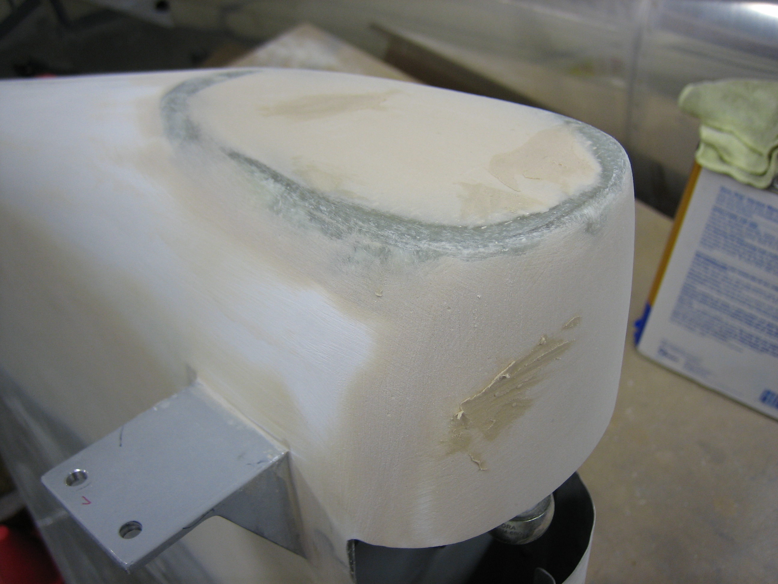
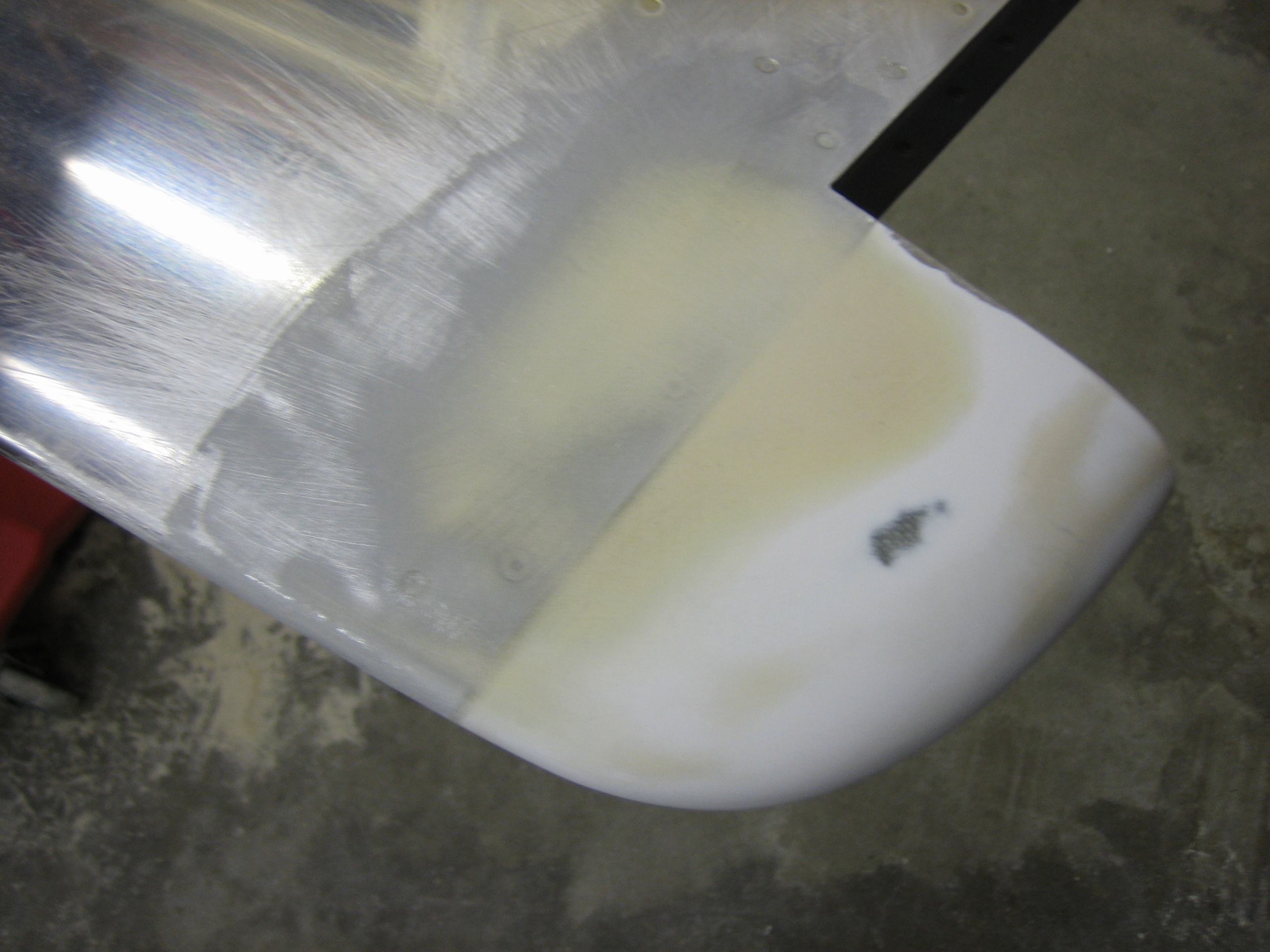
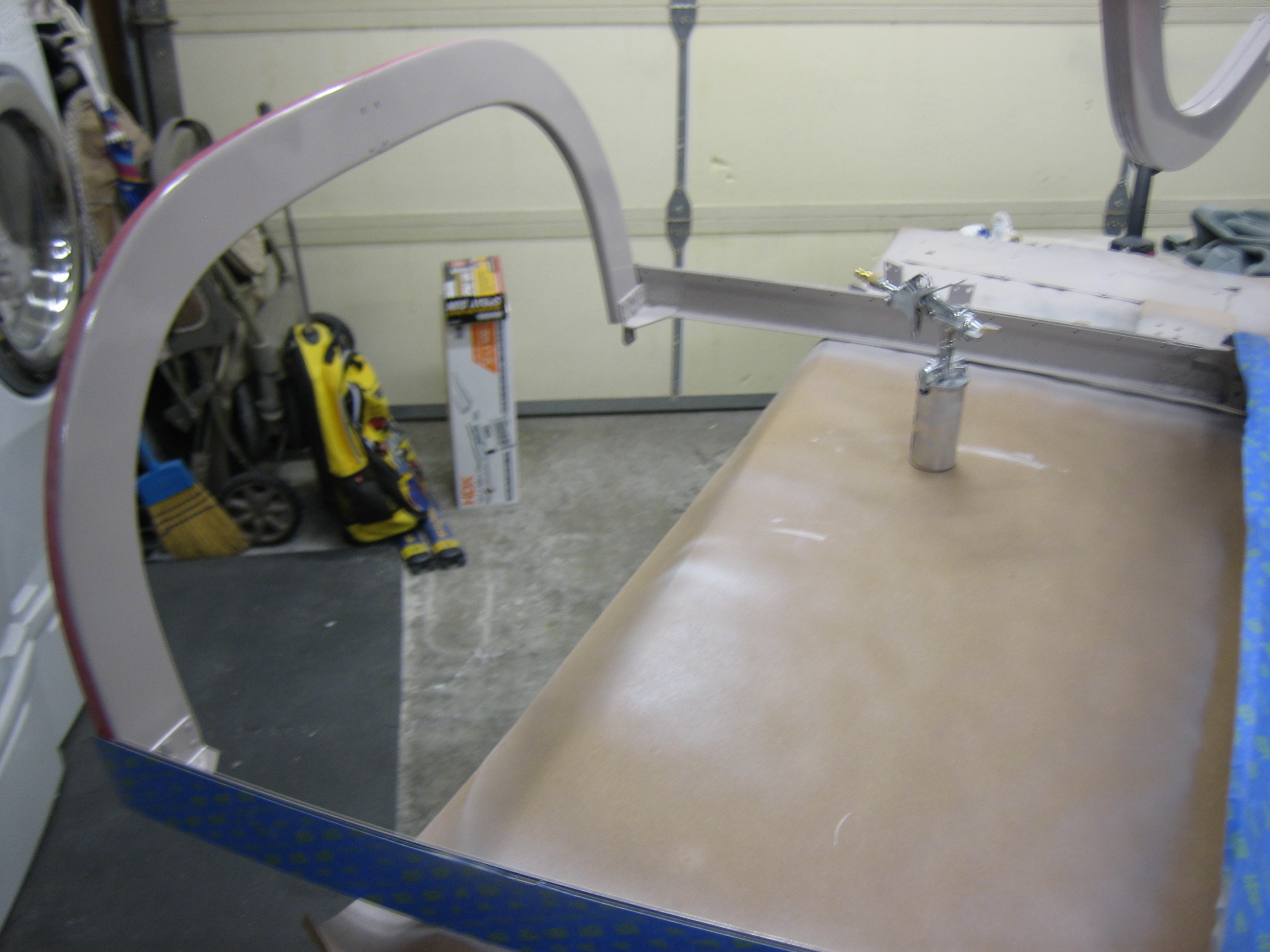
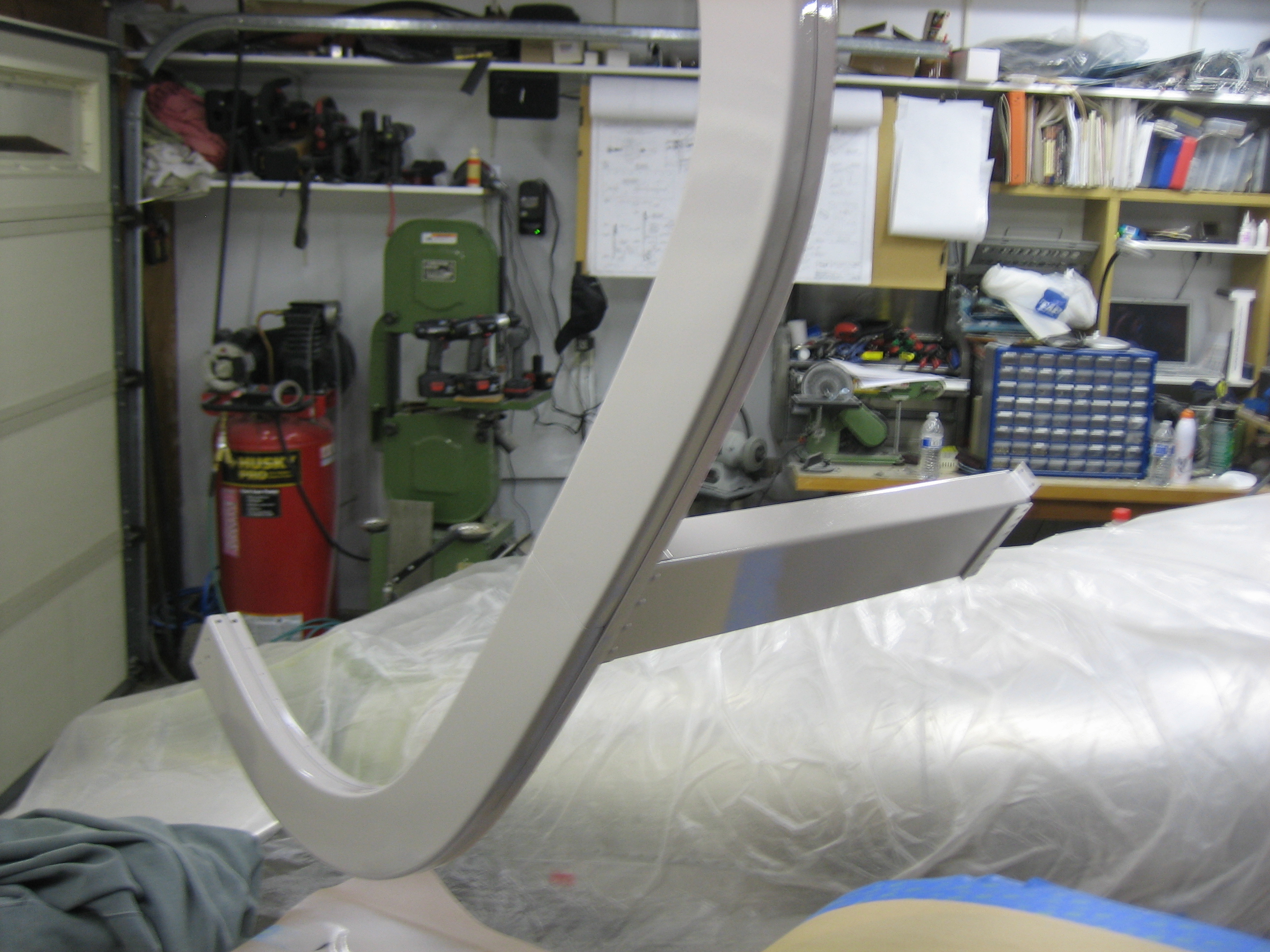
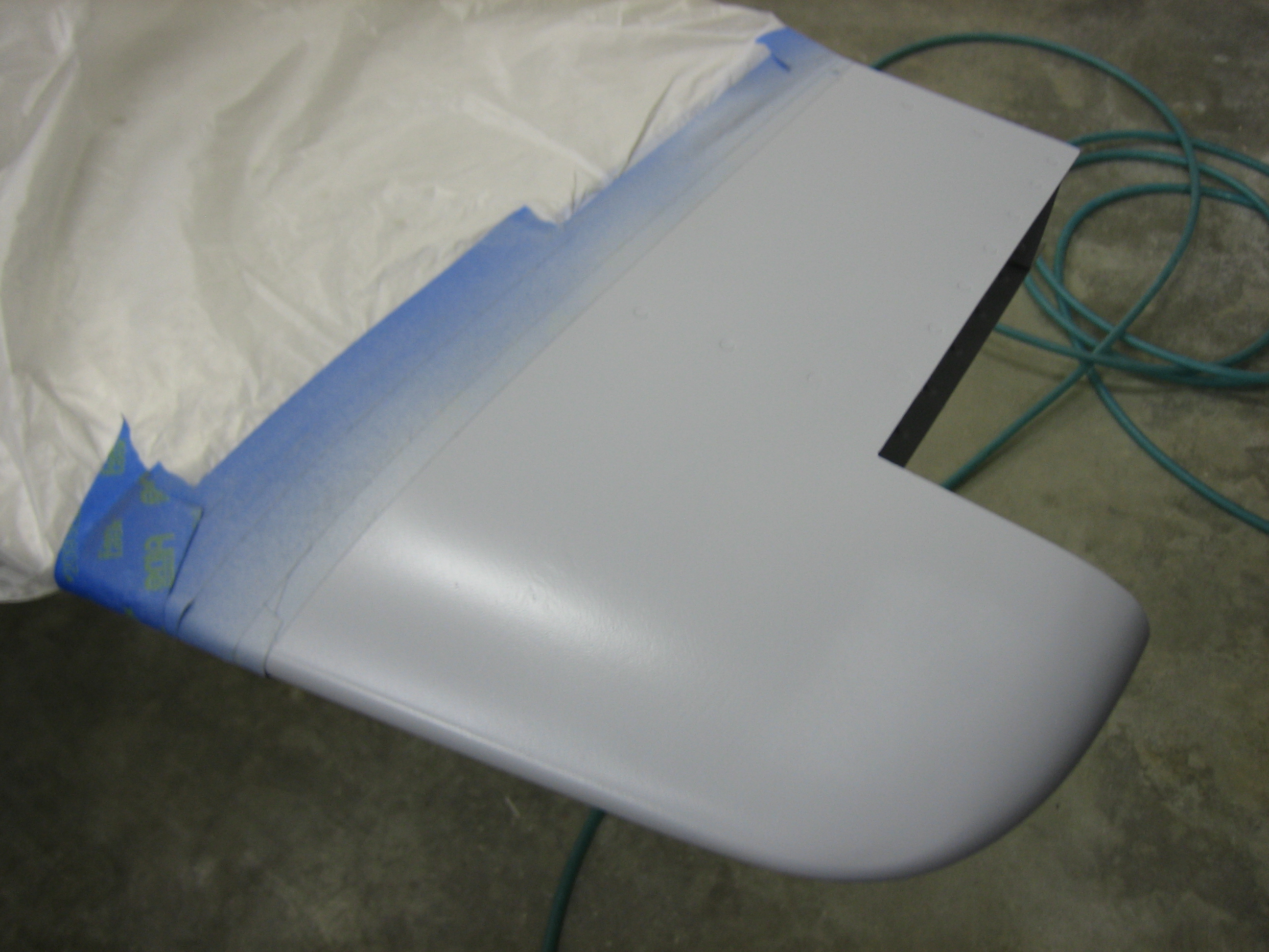
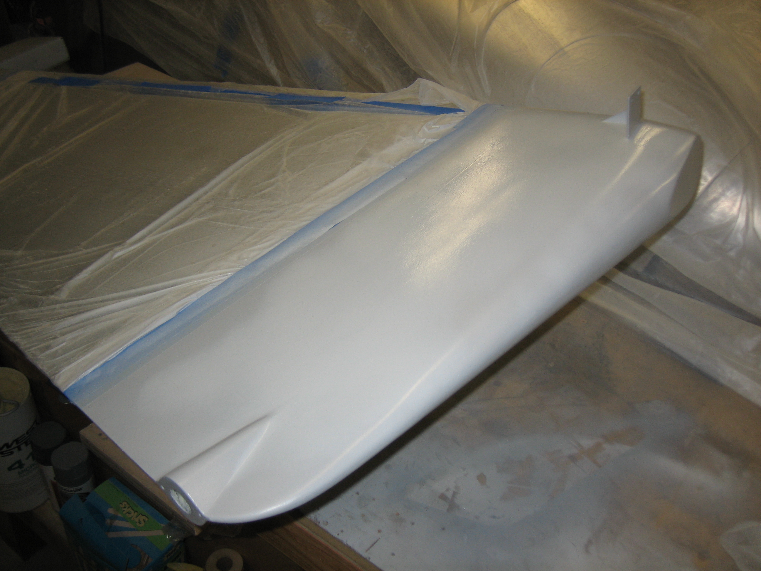
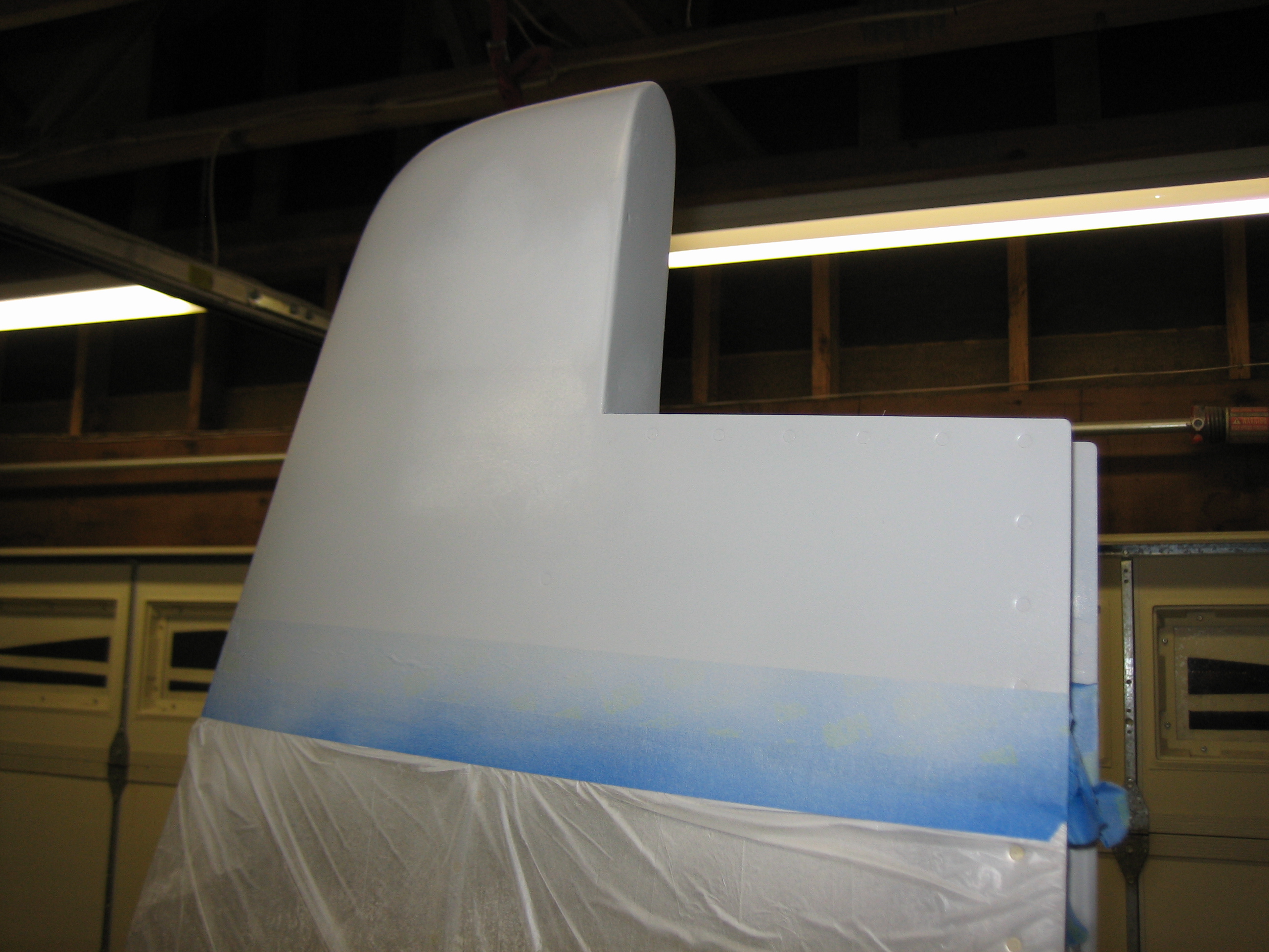
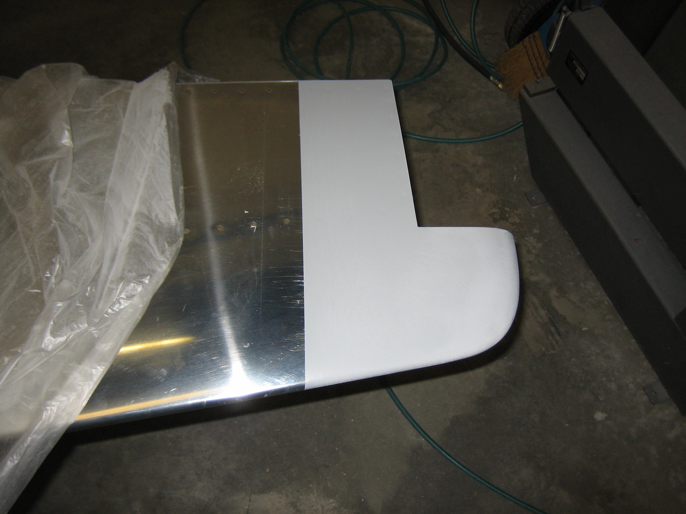
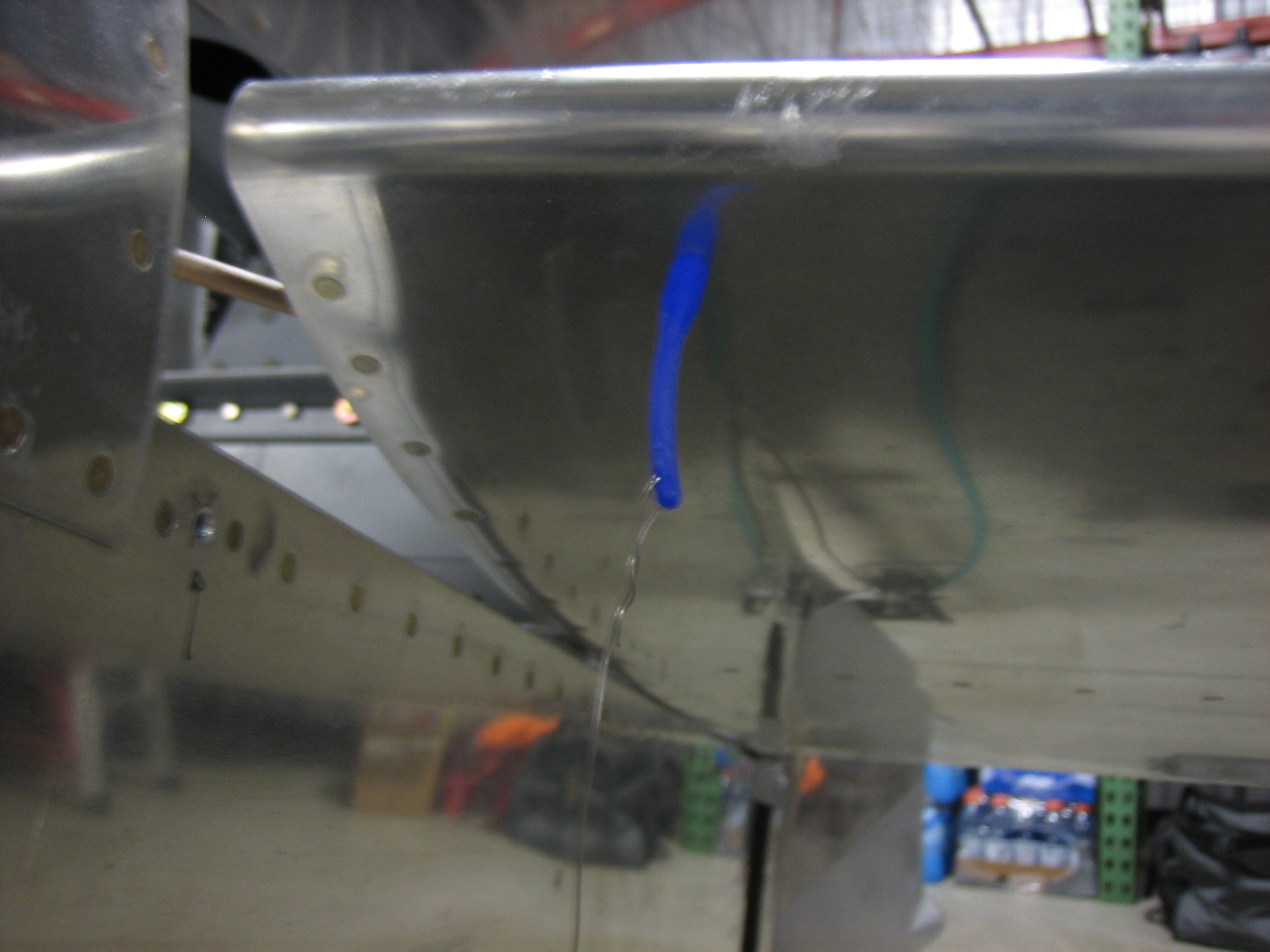
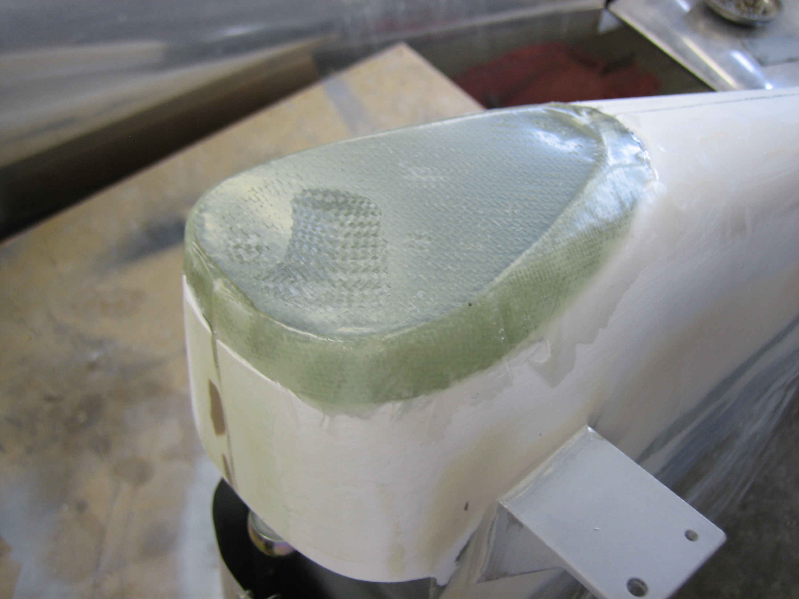
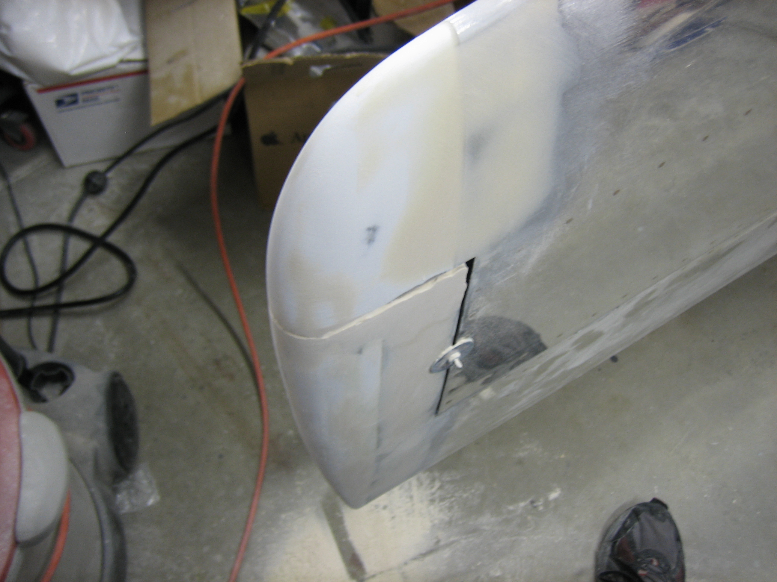
The rudder bottom fairing patch has cured.  After filing down the high spots and giving it a quick sanding, I applied some epoxy/microlight filler.  The leading edge of the fairing also needs to be built up a bit to match the rolled leading edge of the rudder.

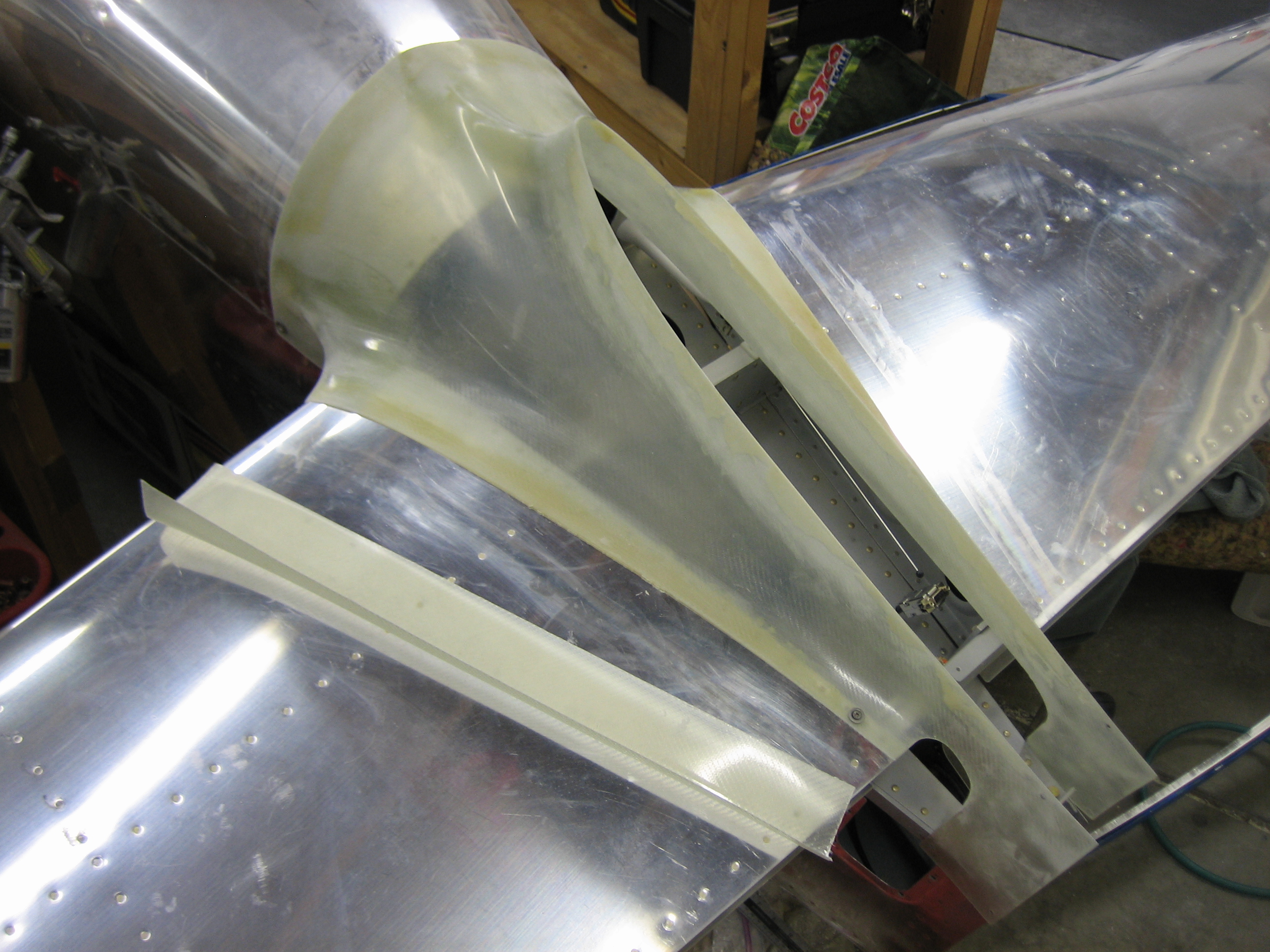
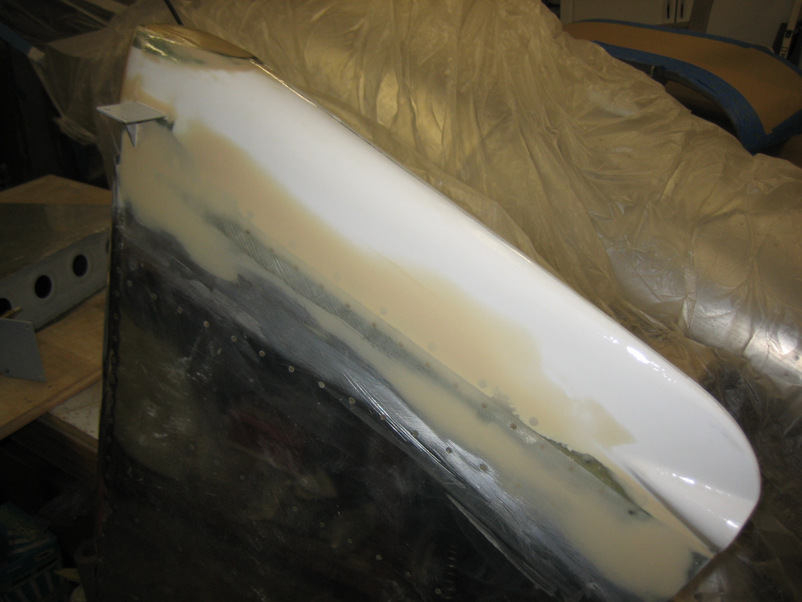
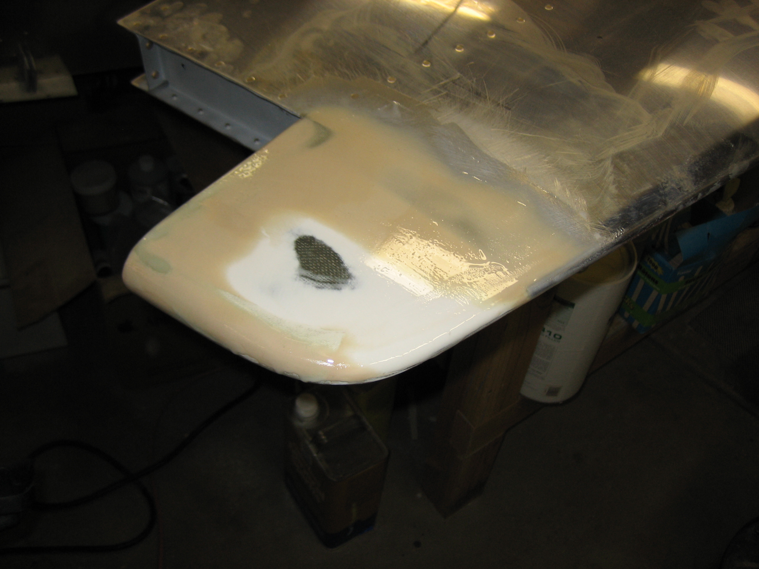
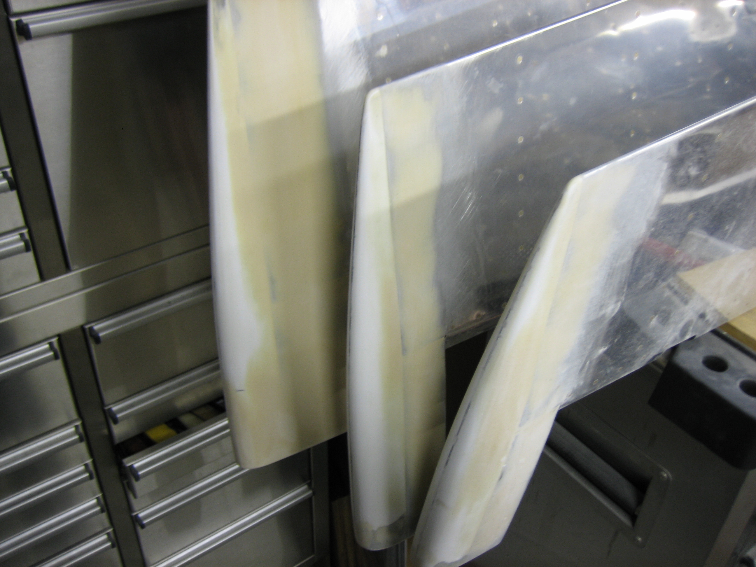
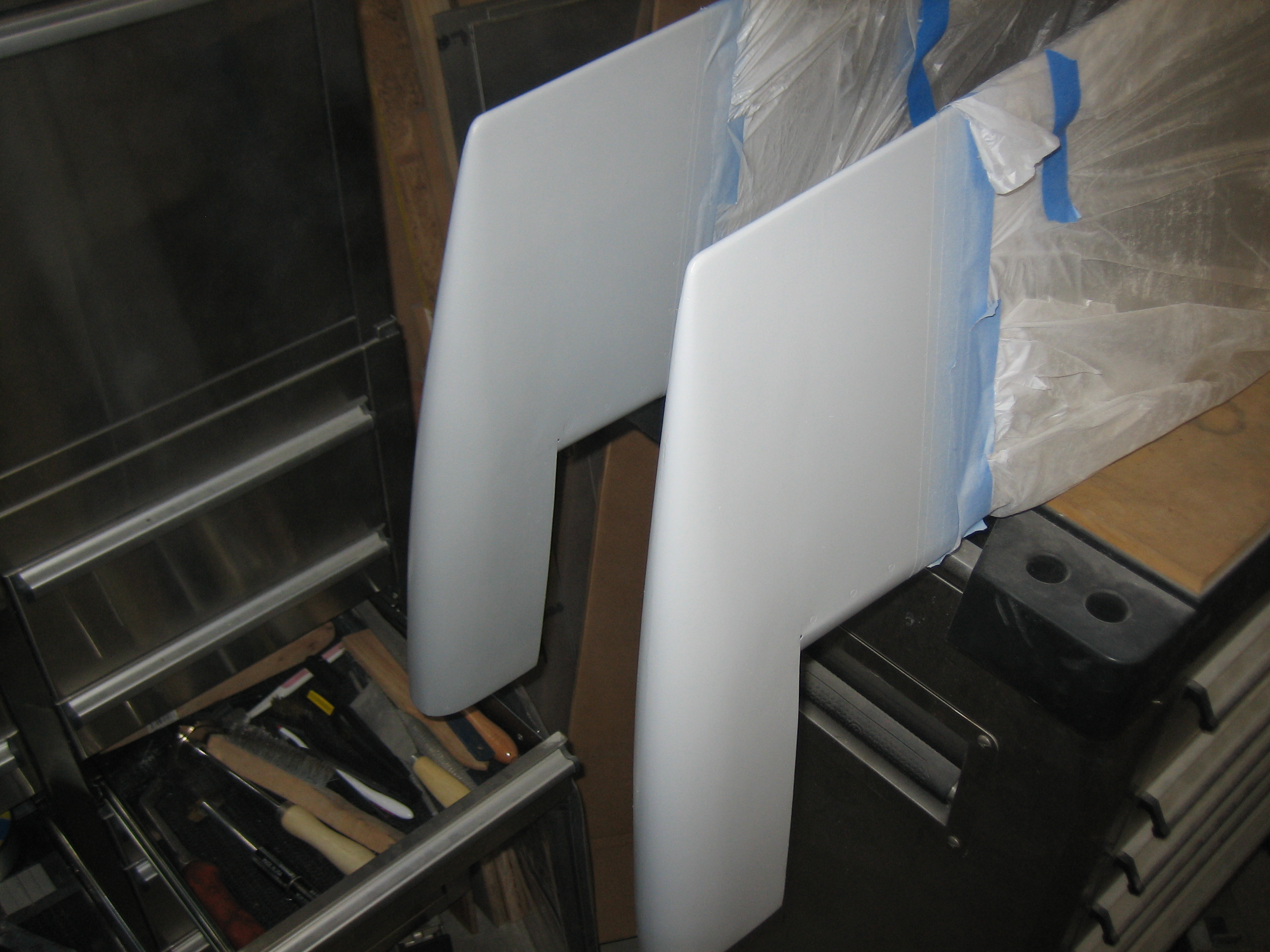
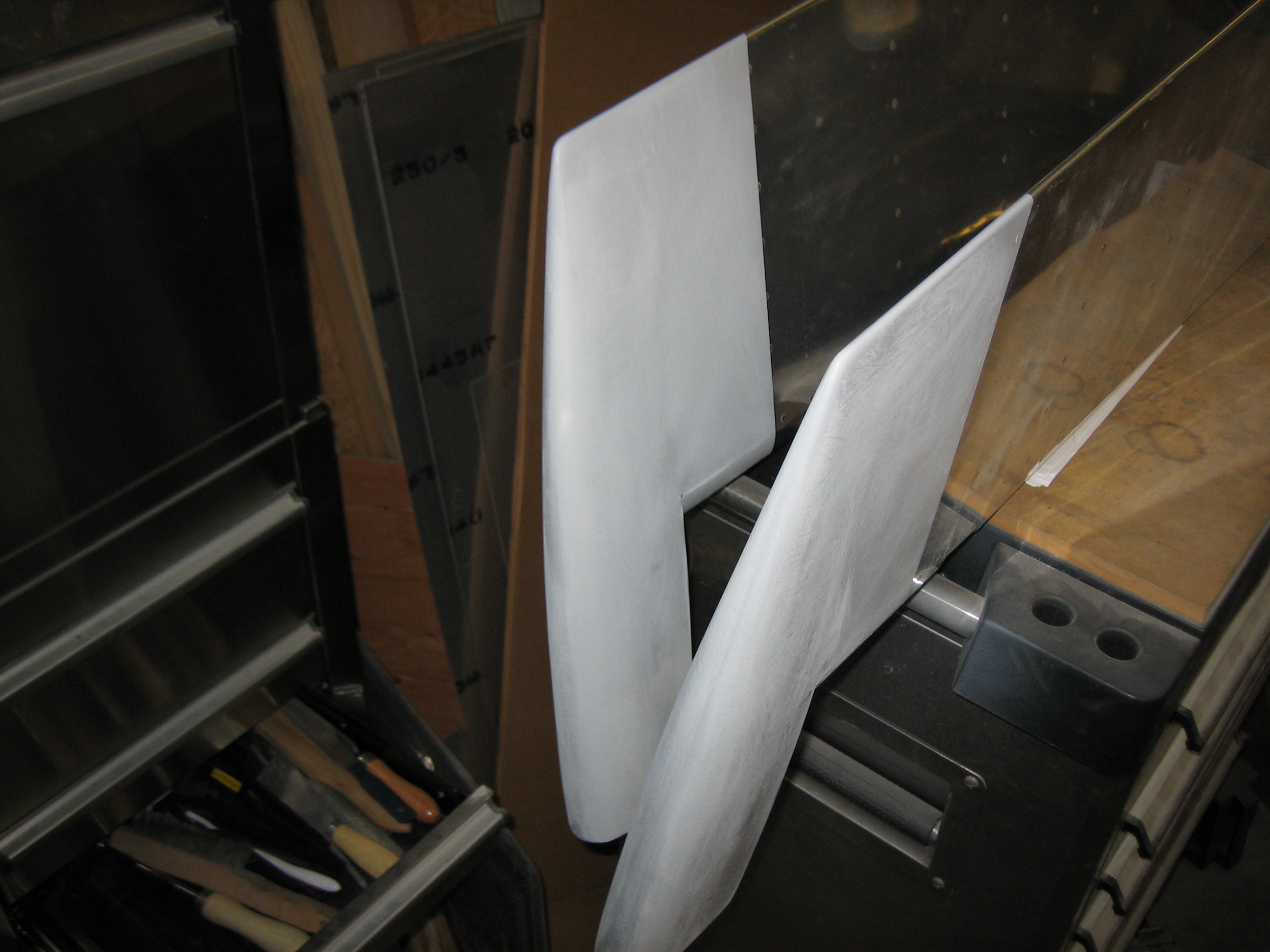
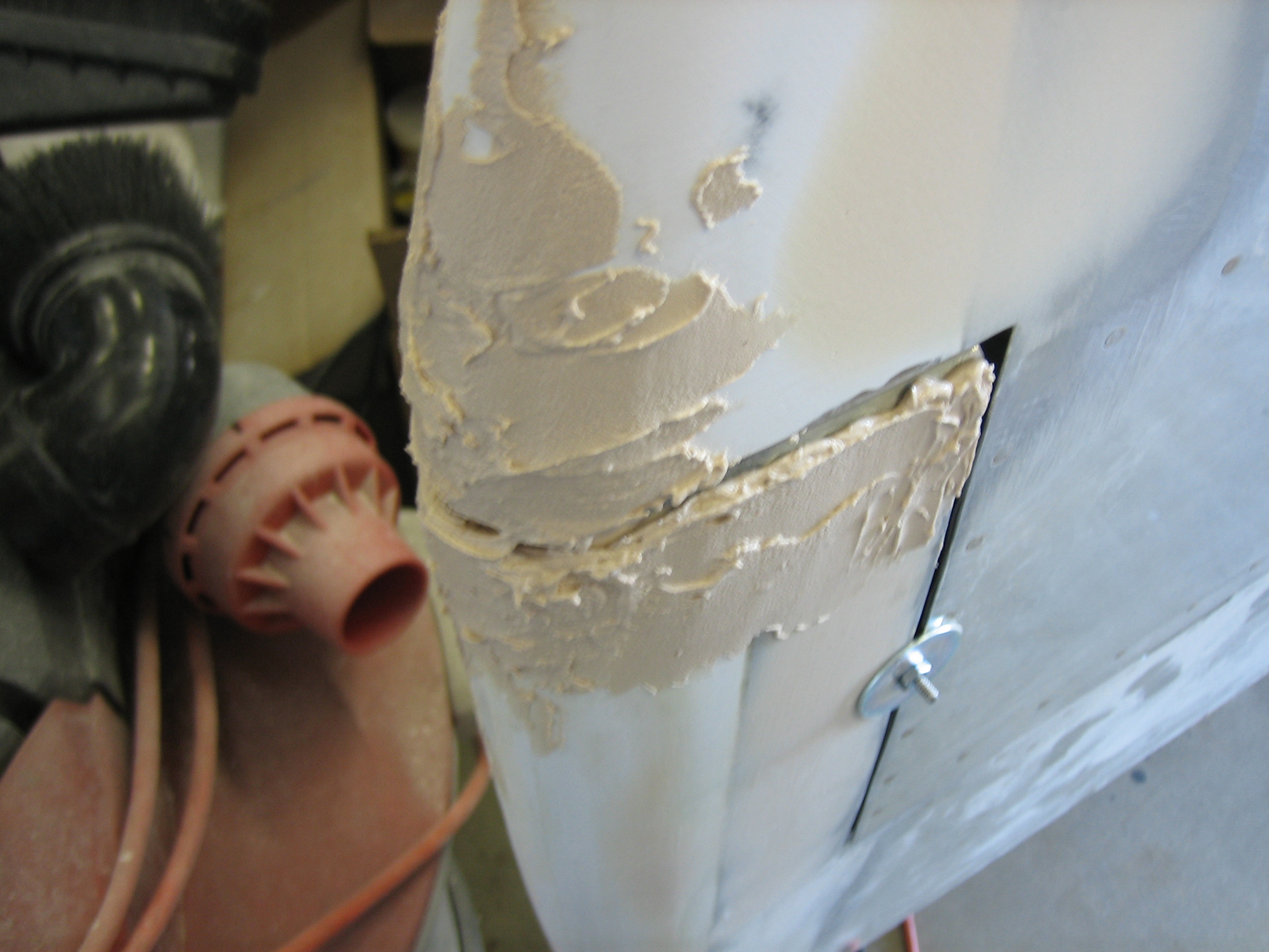
I also added some filler to fair in the horizontal stabilizer and elevators.  Here’s the right side.

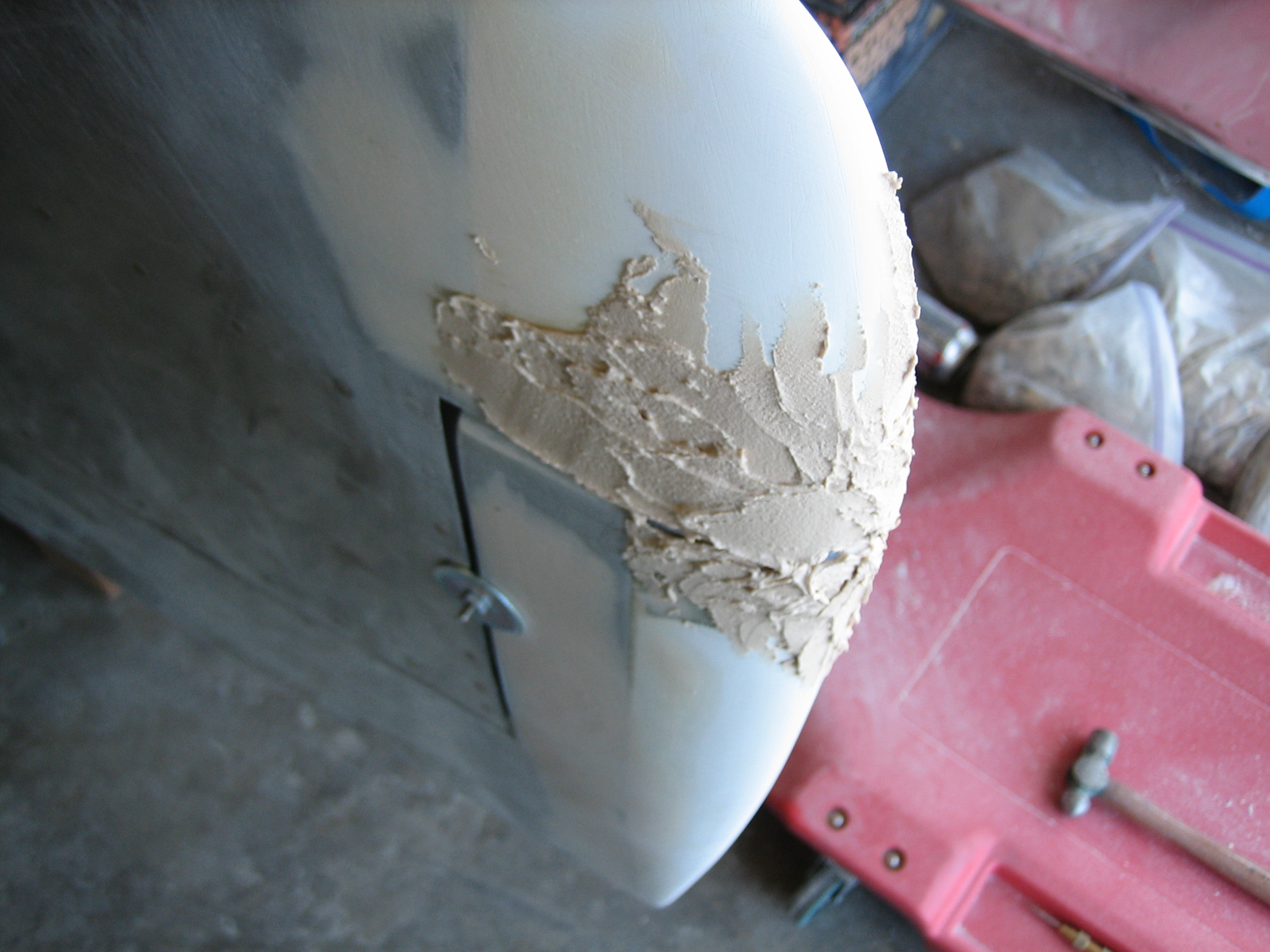
…and here’s the left.

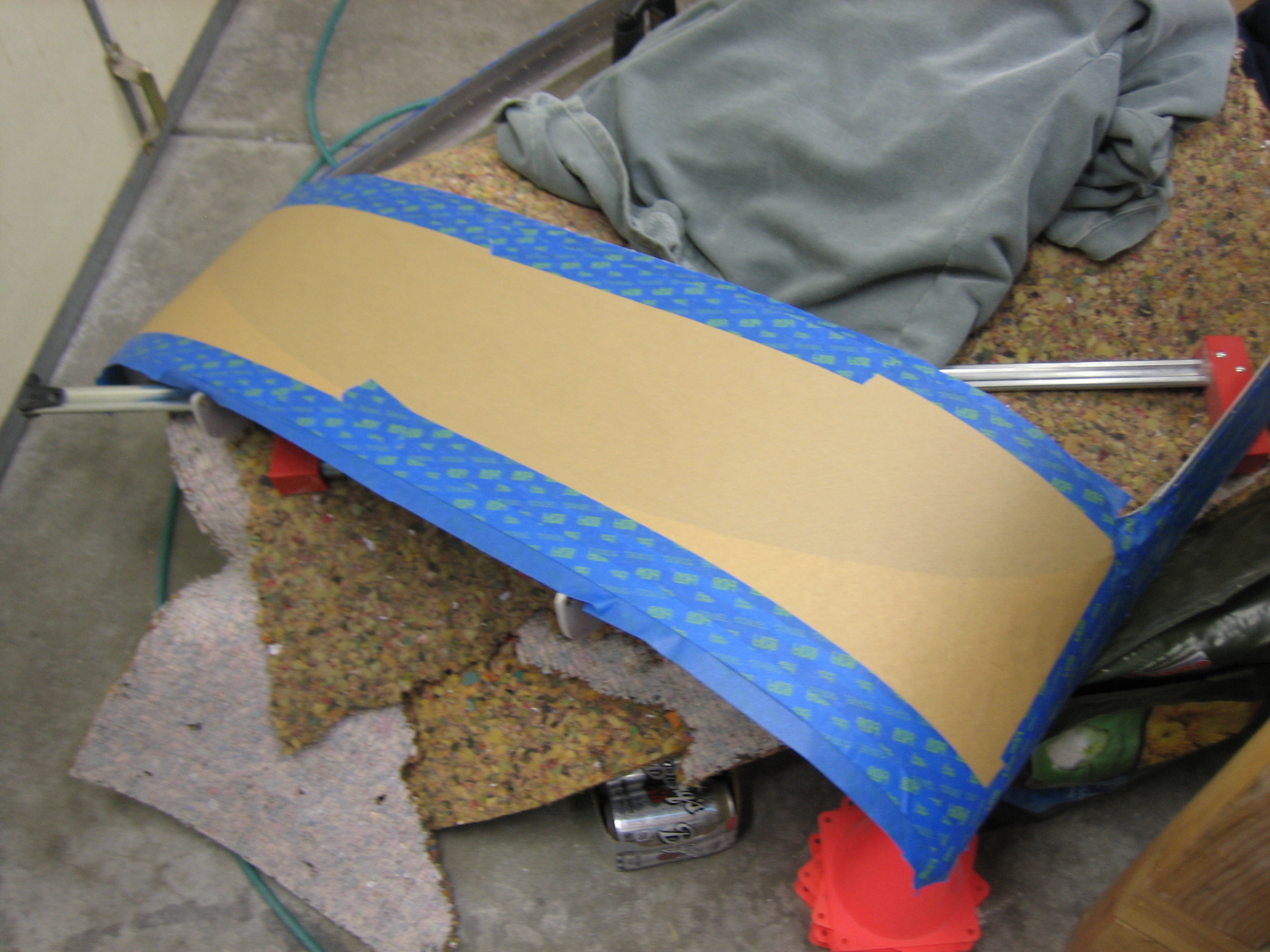
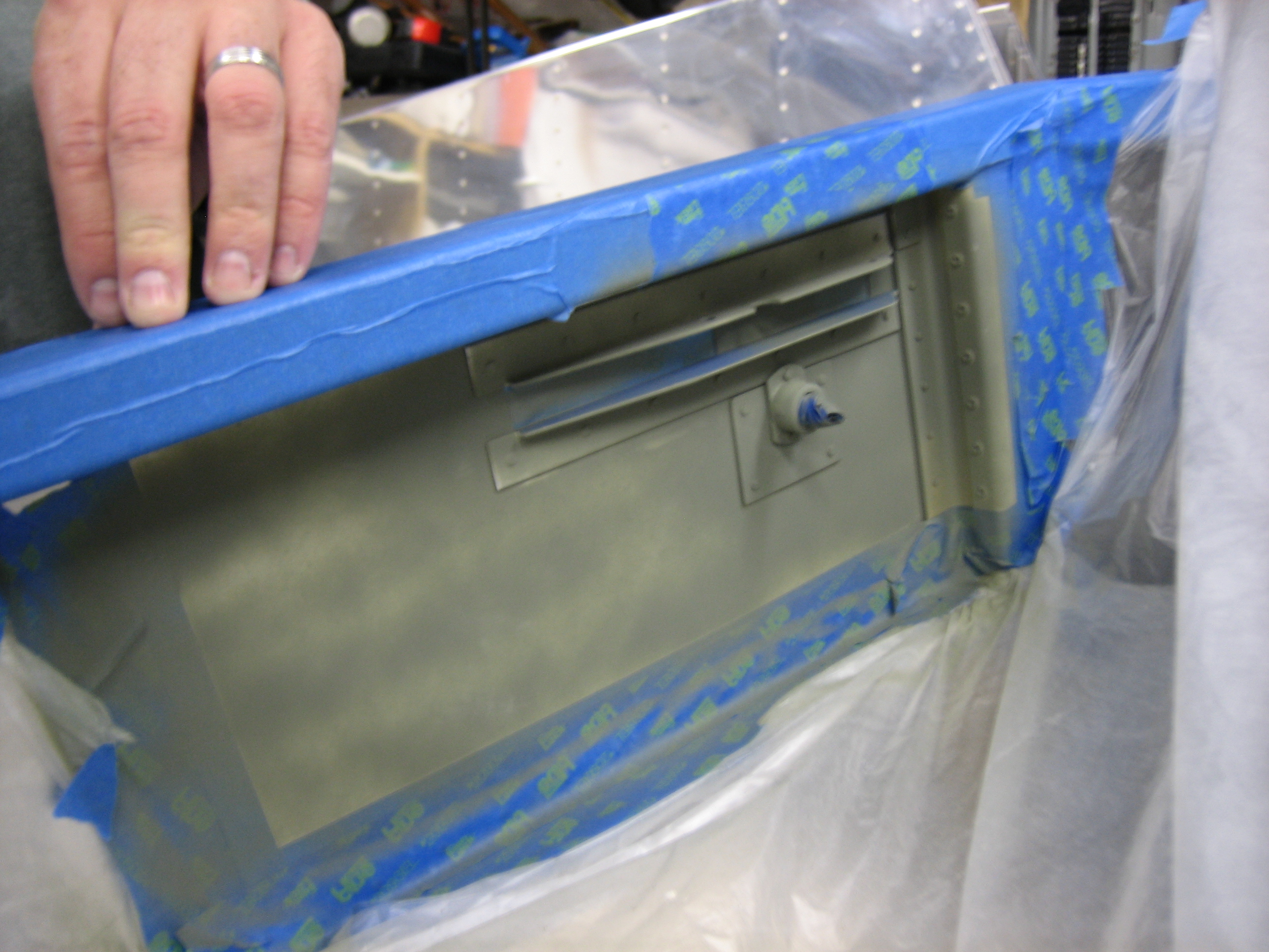
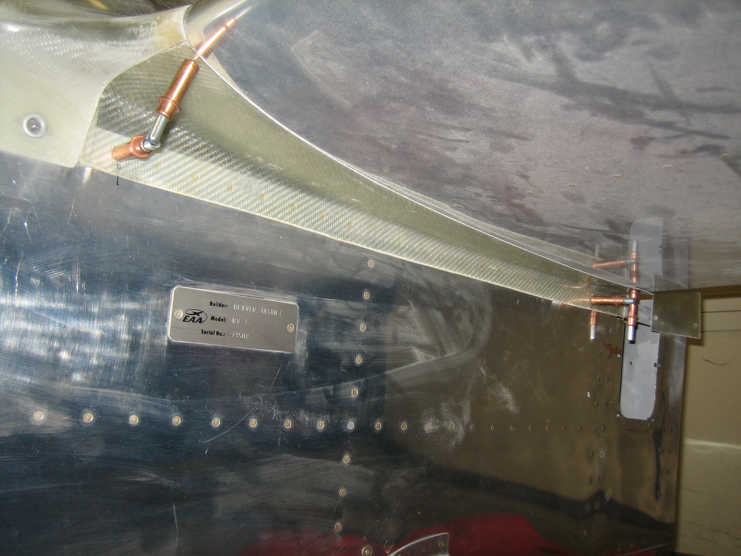
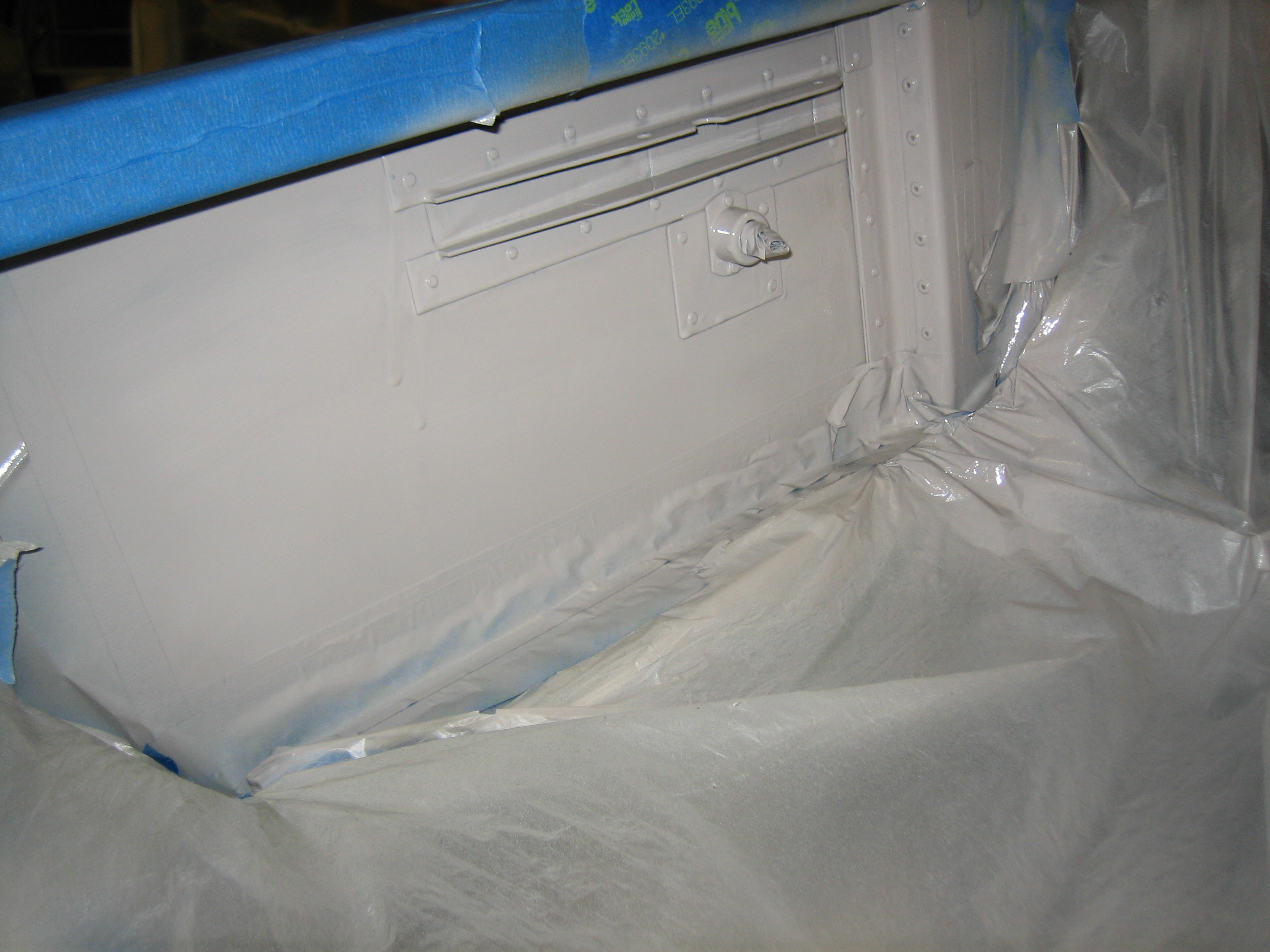
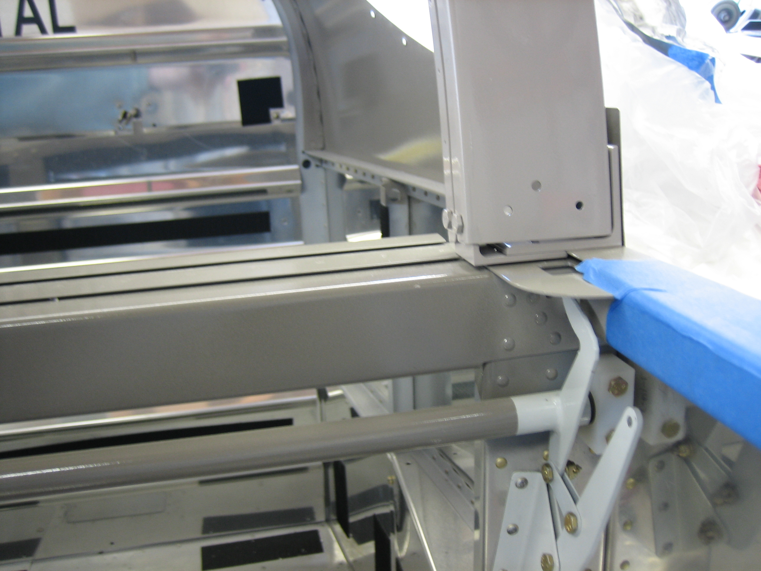
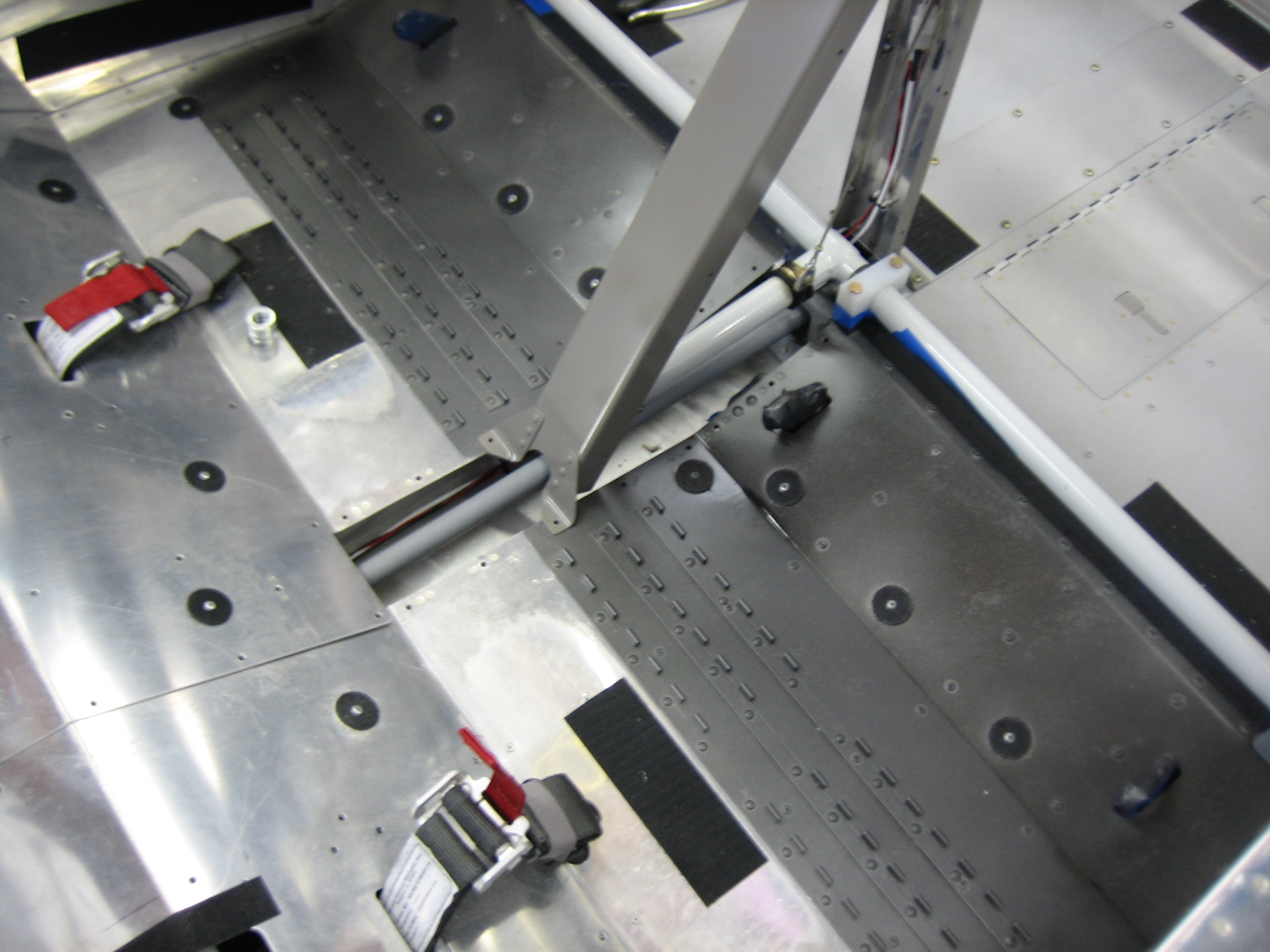
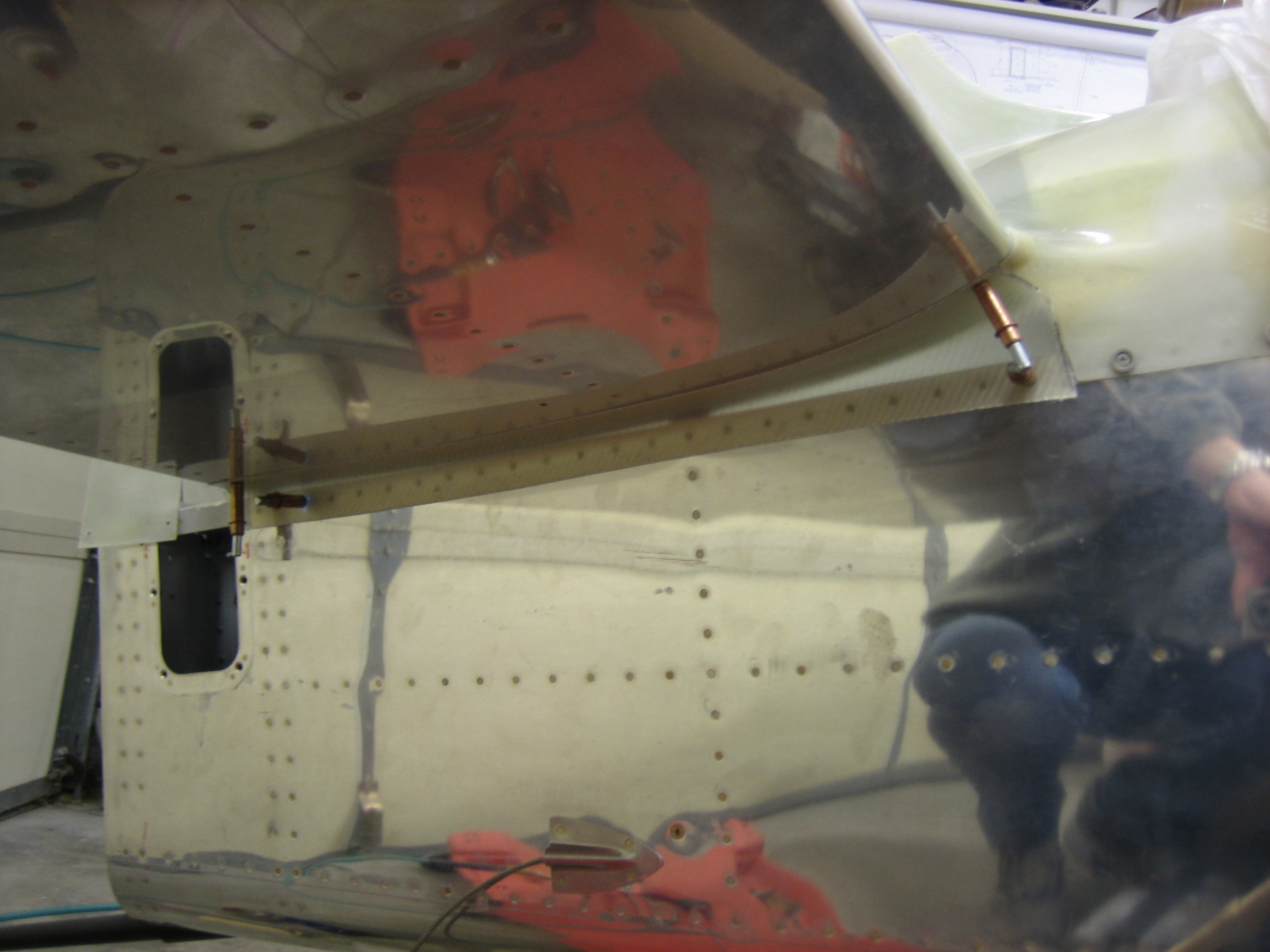
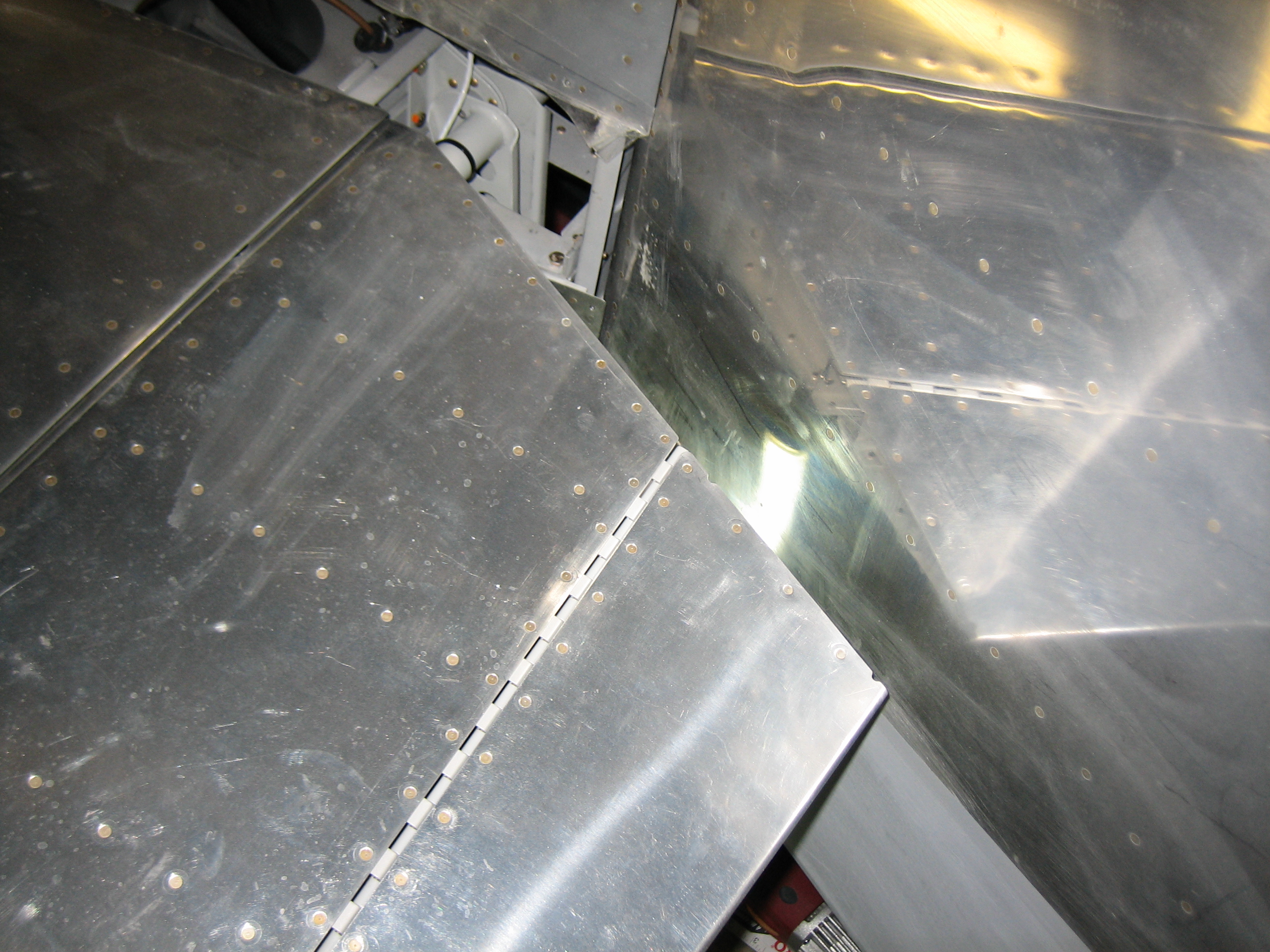
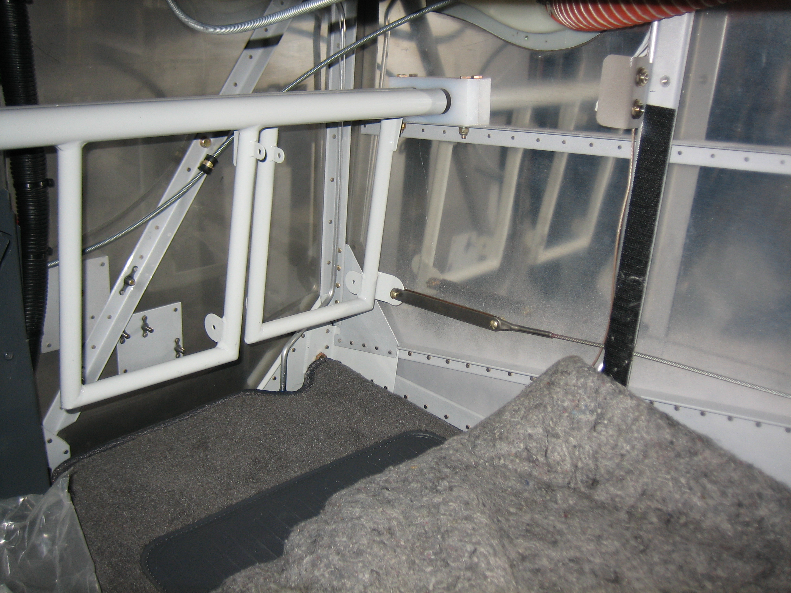
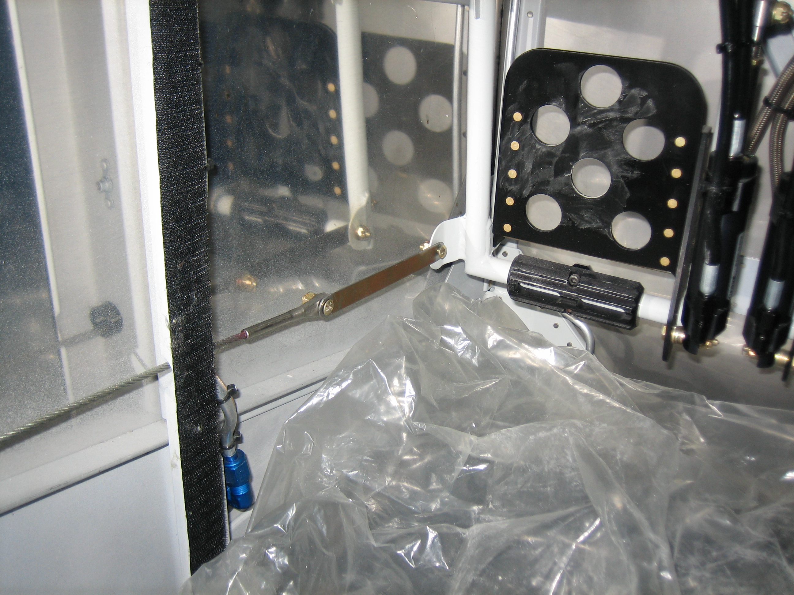
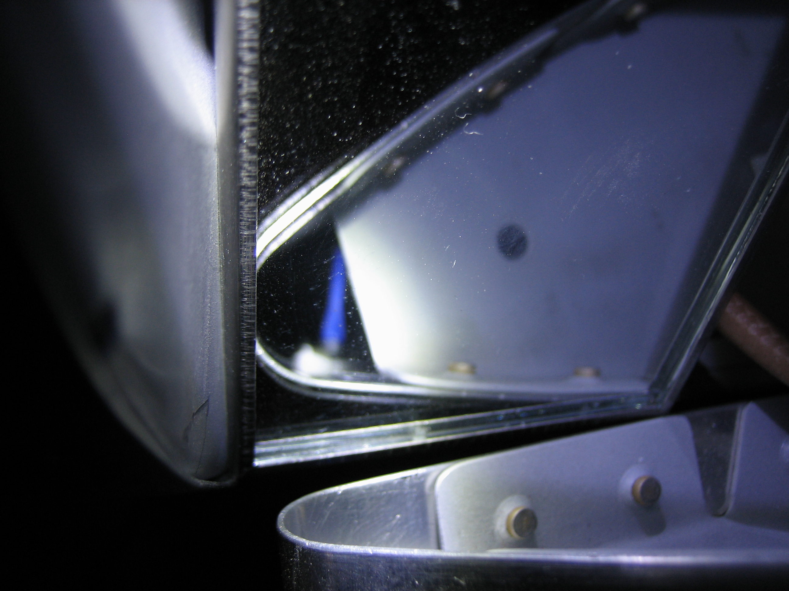
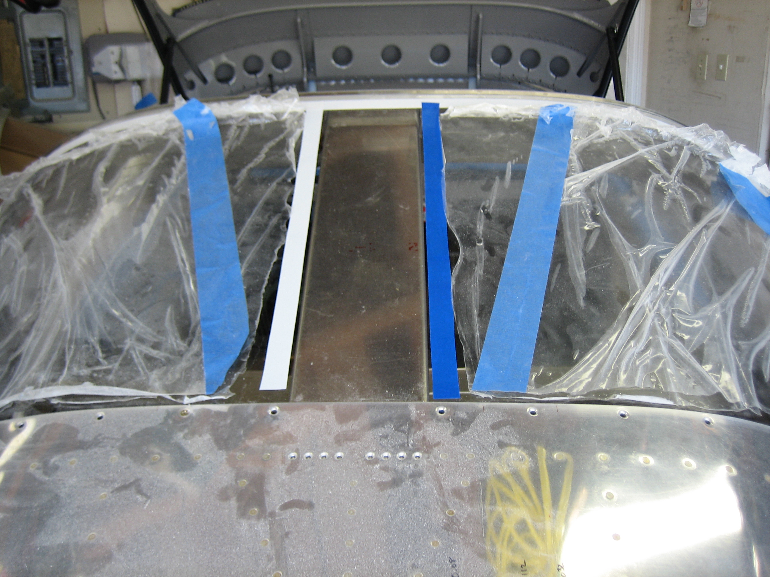
I removed the rear window because the masking tape I applied a few years ago was all dried out and stuck tight.  I used some mineral spirits to soften the adhesive and removed all of the tape.  This took much longer than expected, but I wanted to use a mild solvent to avoid damaging the plexiglass.  After reinstalling the window, I laid a line of tape to mark where the Sikaflex primer will go.

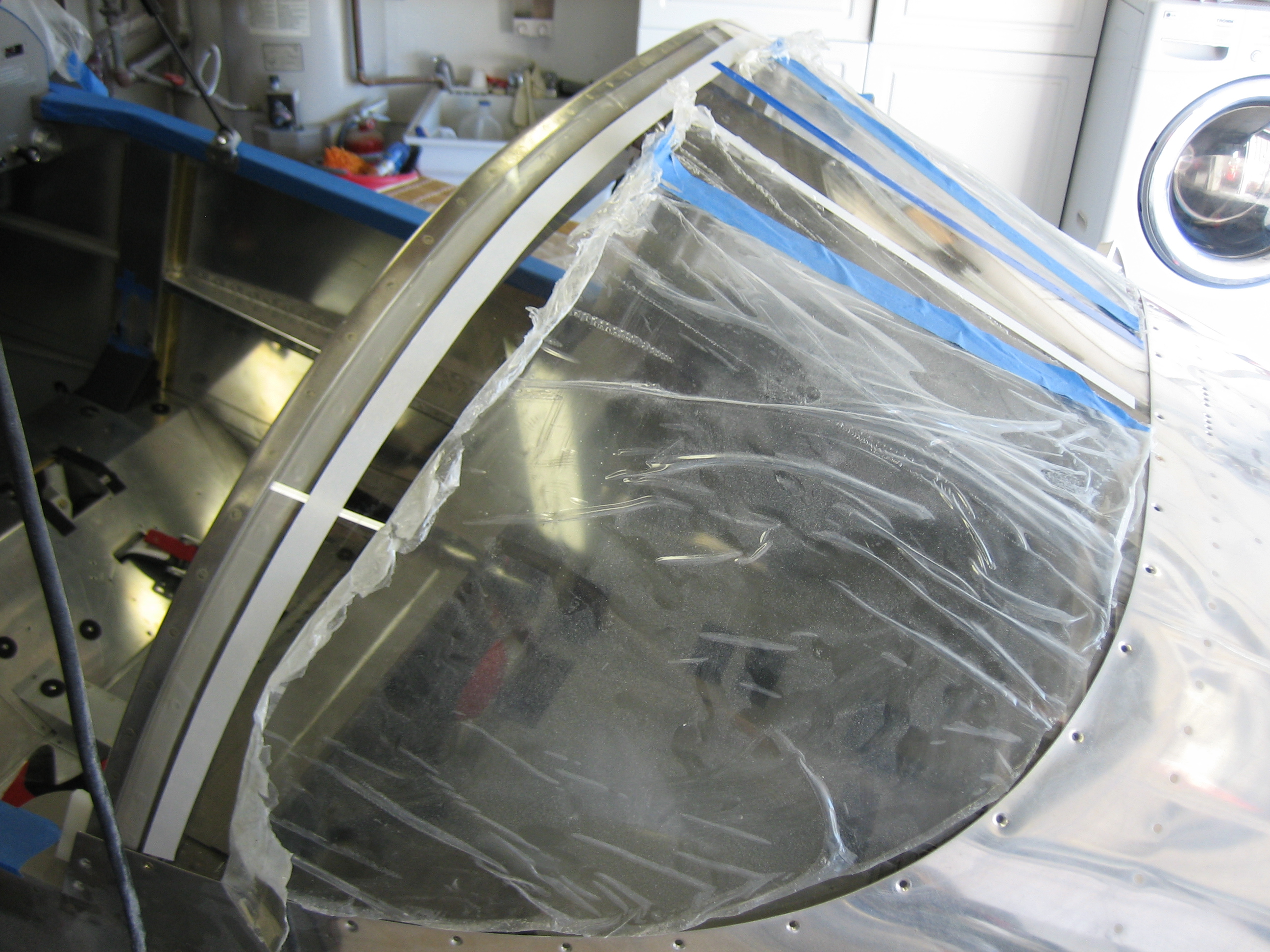
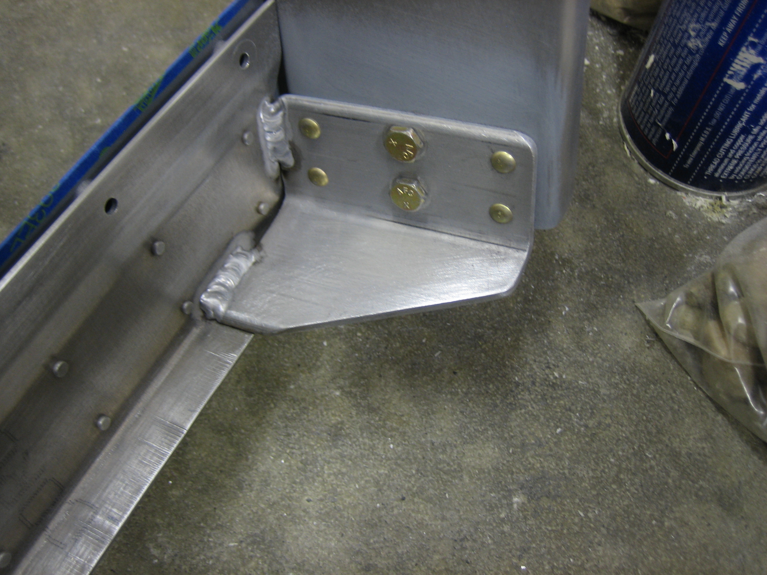
I’m going to paint the inside of the rear window where it passes over the roll bar support channel.  I’ve noticed on other planes that it’s often fairly dusty on top of the channel, and it’s pretty tight against the window, especially toward the back.

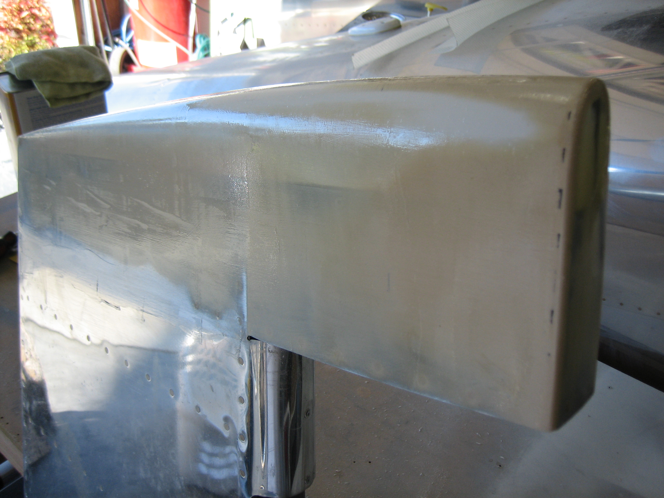
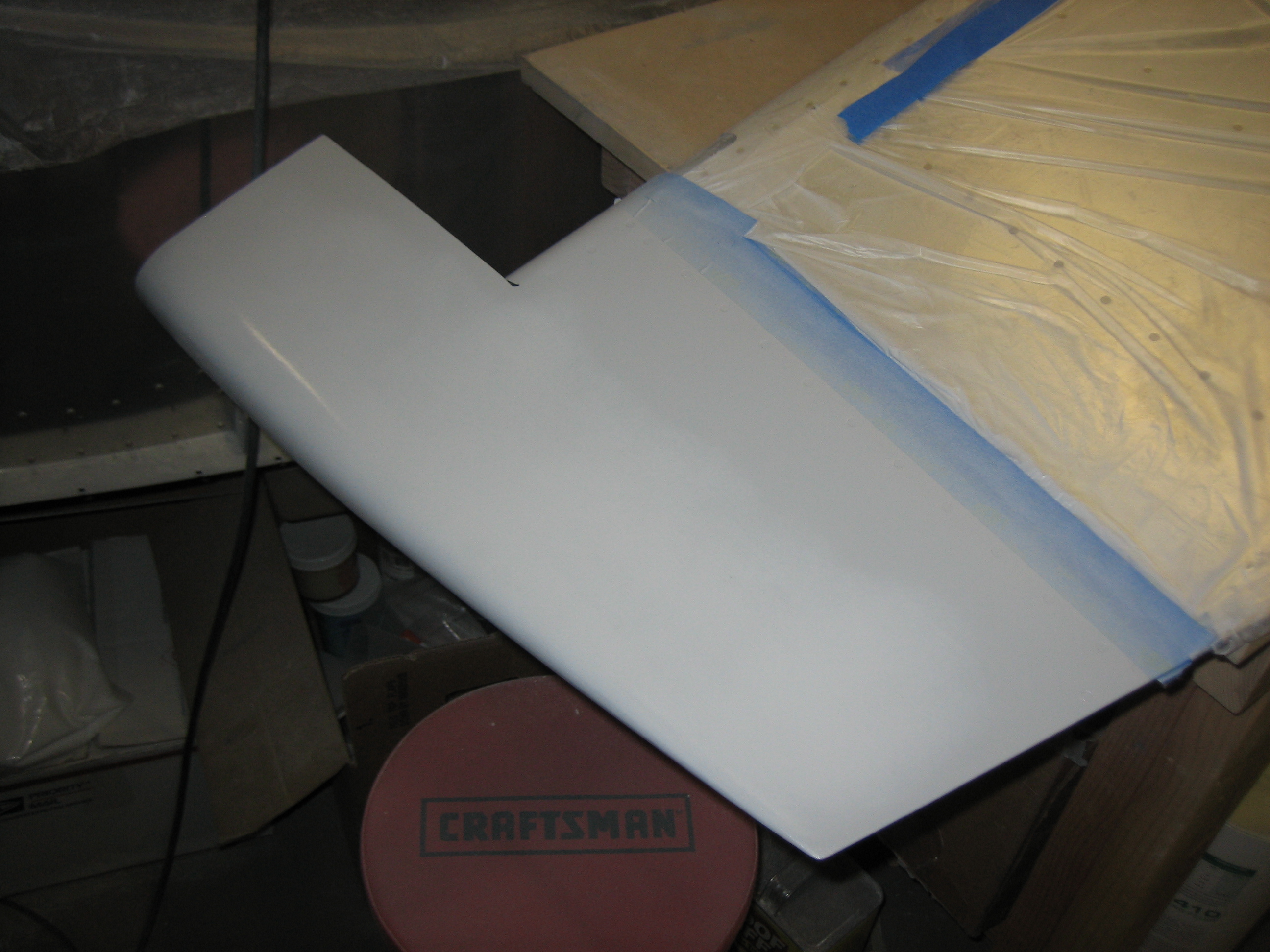
After the horizontal stabilizer and elevator filler cured, I filed and sanded it down so that they’re faired together nicely.

I needed just a little bit more along the leading edges of the elevators.

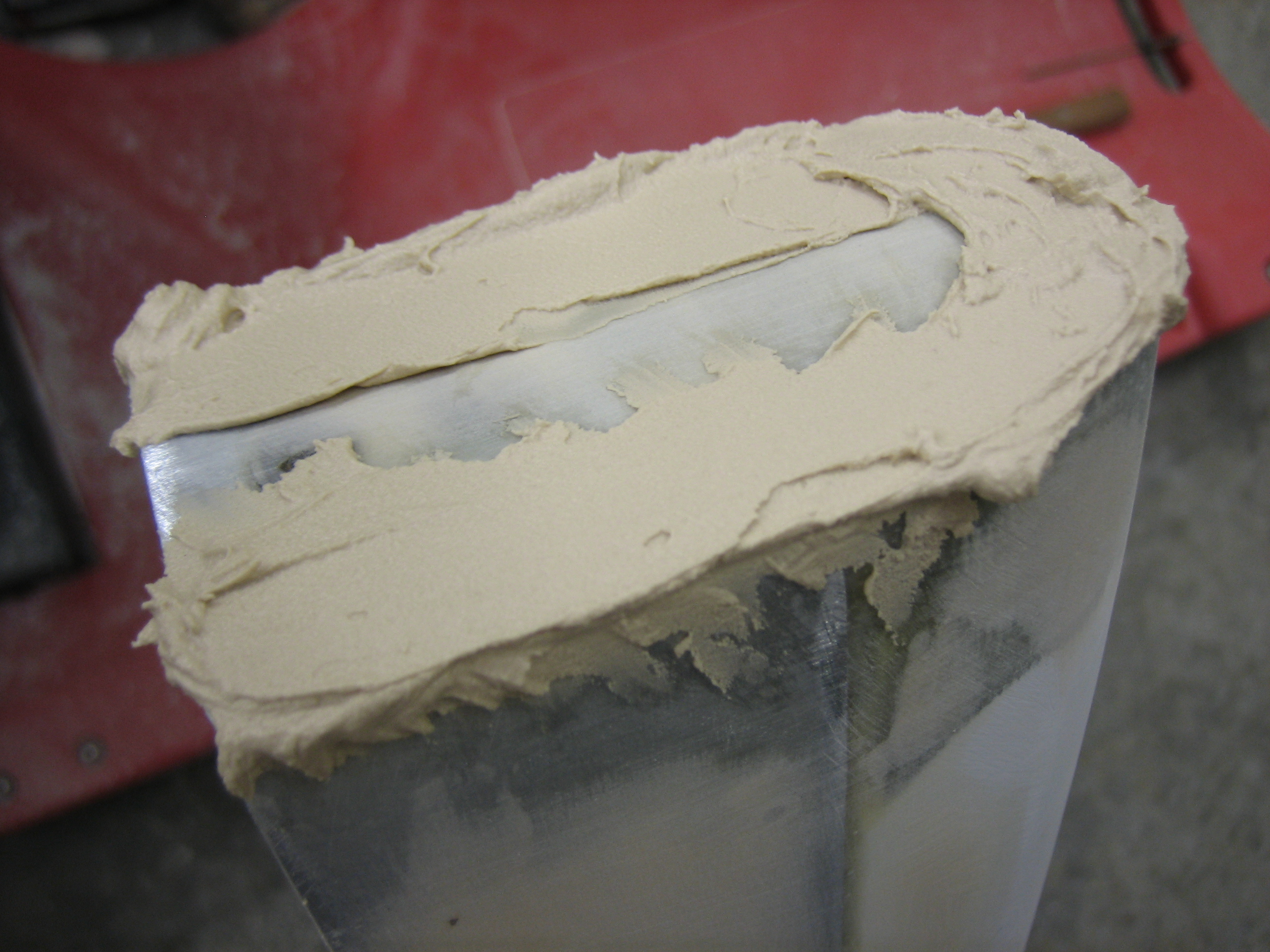
I also sanded down the filler I applied to the bottom of the rudder.  There were a couple of low spots, so I added a little bit more.

Skim Coated Empennage Fairings and Prepped Canopy Frame and Roll Bar for Painting

I skim coated most of the empennage fairings with straight epoxy to fill the pinholes and scratches from the sandpaper.

I then started prepping the canopy frame for painting.  First up is to rivet the canopy bow to the side channel.  I then bolted the canopy latches in place so that all of the hardware will get painted.

I masked off the areas that shouldn’t get any paint, then scotchbrited everything that needed paint.

I riveted the roll bar support channel onto the roll bar, then scotchbrited the whole thing.  I used the scotchbrite disc in the die grinder to make all of the rivets completely flush to the surface to make sure they can’t scratch the canopy.

Riveted Canopy Latch Handle Bracket and Lock, Drilled Lower Left Empennage Fairing

I riveted the mounting angles that hold the canopy latch handle as well as the lock.  I removed the lock’s cam so that it doesn’t get painted since it would just immediately get scratched up.  Afterward, I primed this area with some self-etching primer.

I also drilled the lower empennage fairing to the fuselage and horizontal stabilizer.  The two holes in the fuselage go through the longeron and replace a couple of rivets.  I’ll add standard nutplates here just like the forward holes in the upper empennage fairing.  The rear nutplate in the horizontal stabilizer goes through the flange of the rear spar, and I can use a standard nutplate there as well.  The forward hole just goes into the horizontal stabilizer skin, and the inner rib would make it a pain to install a nutplate there.  My plan is to order a couple of Click Bond adhesive mounted nutplates to install here.

Unfortunately, the fairing doesn’t fit perfectly.  The vertical flange fits nice and tight against the side of the fuselage, but there’s a fairly large gap in the middle between the fairing and the horizontal stabilizer.  I’m going to spend some time with a heat gun to see if I can reshape it to fit better.

Painted Remaining Interior Components

I thought I still had some interior paint left over, but it had gone bad in the can.  I called yesterday and had to have a quart overnighted to me.  It came today, so I wrapped up the painting.  Here’s the inside of the cabin where the sidewall will be visible behind the interior panel.

Here’s a bunch of the smaller parts with final paint.  I might end up having to reshoot the roll bar support channel cover since I think some dust settled on it.

Here’s the canopy frame.  The red stripe along the arch is some electrical tape that is masking off where the Sikaflex primer will go.

Here are the roll bar and support channel.

I also mixed up some epoxy and skim coated the final parts of the empennage.  Here’s the rudder bottom fairing.

And here’s the top of the vertical stabilizer.

Painted Under Seat, Finished Sanding Control Surface Fairings, Finished Drilling Lower Empennage Fairings

Well, this sucks.  The replacement can of paint doesn’t remotely match the original color they sent me.  I’m going to have to call them tomorrow and probably send a sample down for them to match.  I was hoping to start installing the canopy today, but this probably delays that a week.  Oh well, I have plenty of other things to work on.

I painted the floor a dark color that pretty closely matches the carpet.  It doesn’t have to match exactly since you only see tiny bits of it.

I finished sanding all of the control surface fairings.  These are ready for a coat of primer.

Finally, I drilled the right side lower empennage fairing to the horizontal stabilizer and fuselage.

Primed Empennage Tips

I shot a fairly thick coat of epoxy primer on the empennage tip fairings.  This should hopefully fill all the scratches from the previous sanding and smooth things out nicely.  Here’s the left horizontal stabilizer tip.

And here are the elevator tips.

This is the top of the rudder.

…and here is the bottom.

Finally, the top of the vertical stabilizer.

Sanded Primer on Empennage Tip Fairings

I sanded down all of the primer to level the surfaces of the empennage tip fairings.  I’m reasonably happy with how these turned out, but they could definitely use some more sanding and filling to be perfectly flat.  I may leave that for the painter though (assuming they will do that).

You can see some of the filler and gel coat color through the thin spots in some of the coats where I had to sand fairly aggressively to remove the scratches.

Adjusted Rudder Stop and Fabricated Rudder Pedal Links

The rudder stop needed a bit of trimming to allow the rudder to reach maximum deflection.  The stop is made of some sort of plastic that is tough to trim, but I finally stumbled on using my oscillating multifunction tool with a sanding pad attachment.  This made quick work of the stops and I can now swing the rudder 35º each side of center.

35º results in 1 1/8″ clearance between the rudder and the end of the elevator.

Now that I had the full rudder swing, I could measure for and fabricate the steel links that connect the rudder pedals to the rudder cables.  I needed 5″ on the right, so I started with fabricating two of those and installed them.

Next, I clamped the rudder in trail with the vertical stabilizer and then clamped the rudder pedals together so that they were aligned.  I then measured the left side at 4 7/8″.  I only had enough steel to fabricate one of the two pieces, so I’ll have to pick up some more.  I’m going to have to adjust the pedal geometry.  Right now, the brake pedals are too far back and it would be hard to avoid hitting the brakes when using the rudder.  Fortunately, the Grove master cylinders are somewhat adjustable, so I’m hopeful that I can find a geometry that works.

Leak Checked Pitot System, Empennage Nutplates, Unusable Fuel and Firewall Passthroughs

I spent some time this morning working on the left wingtip lens before heading down to the hangar.  Since I reworked the pitot and AOA tubing yesterday, I wanted to leak check it today.  I disconnected the tubing at the new fitting in the wing inspection panel and attached some 1/4″ ID latex tubing.  I could roll up the other end of the tubing to increase the pressure in the pitot system and test for leaks.  AC 43.13 recommends increasing the pressure to an indicated airspeed of 150kts and then clamping the tubing for 1 minute to check for leaks.  As long as the leaks aren’t substantial enough to cause the indicated airspeed to drop more than 10kts, then everything is fine.  After 1 minute, I had a 3 kt drop, so I’m in great shape.

Next, I tackled installing the two Click Bond nutplates in the horizontal stabilizer.  I used some hemostats to scotchbrite and solvent wipe the inside of the horizontal stabilizer around the hole and then fished some 0.025″ safety wire up through the hole and out through the nose of the inboard end of the horizontal stabilizer.  I pushed the safety wire through the end of the silicone installation plug so that I will be able to pull it back through the hole.

The Click Bond adhesive I had had dried up, so I mixed up some epoxy with West System 404 structural adhesive filler.  I applied a little bit on the flange of the nutplate and then pulled it through the hole.

Here’s a picture taken through a mirror at the installed nutplate.  Once the adhesive cures, I can just pull out the silicone plug.

With the new fuel pump installed, I decided to determine the unusable fuel.  I rigged up the hose from the spider so I could capture any fuel pumped to the engine.  I dumped 16 oz into each wing and then ran the fuel pump until nothing came out.  Finally, I drained the fuel in each tank to see how much unusable fuel there was.  I drained almost 7 oz from the left tank and 6 oz from the right tank.  I then dumped the fuel back in the tanks so that it could be included in the weight and balance.

My buddy Greg noticed that the firewall pass-throughs didn’t grip these cables very securely.  I removed the eyeballs and wrapped a couple of layers of aluminum tape around each cable and then reinstalled them.  The cables are rock solid now.