Configured VP-X and SkyView

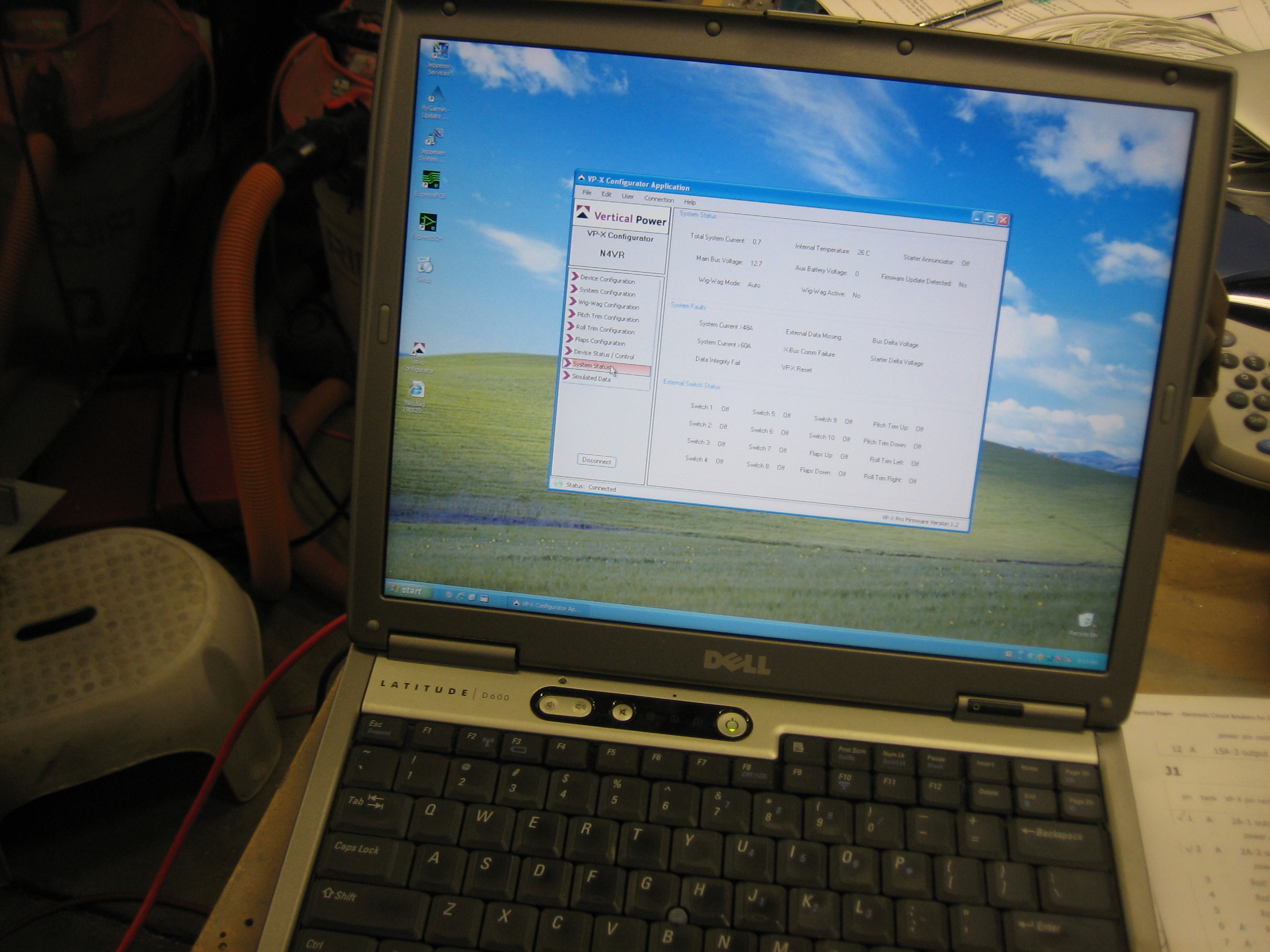
With the VP-X installed and running, I connected a crappy old PC laptop (I stopped using Windows many many years ago).  I ran the VP-X Configurator and configured all of the devices and verified all of the switches are sensed properly.

After upgrading the SkyView screens to 3.2 and entering the VP-X license code, I configured the serial port to talk to the VP-X.  It wasn’t immediately obvious how to get the VP-X screen to appear, but a quick glance at the SkyView installation manual revealed the method.

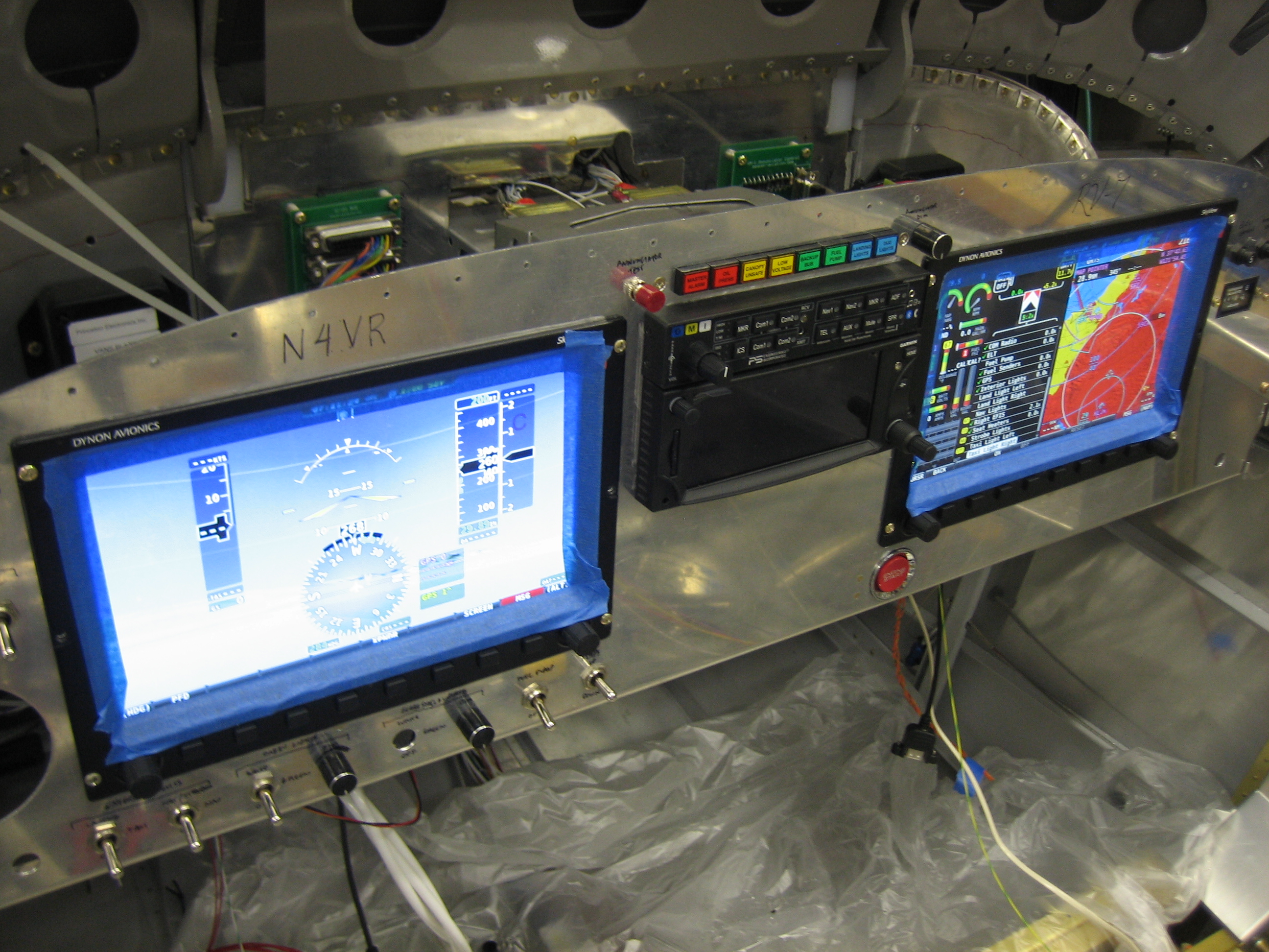
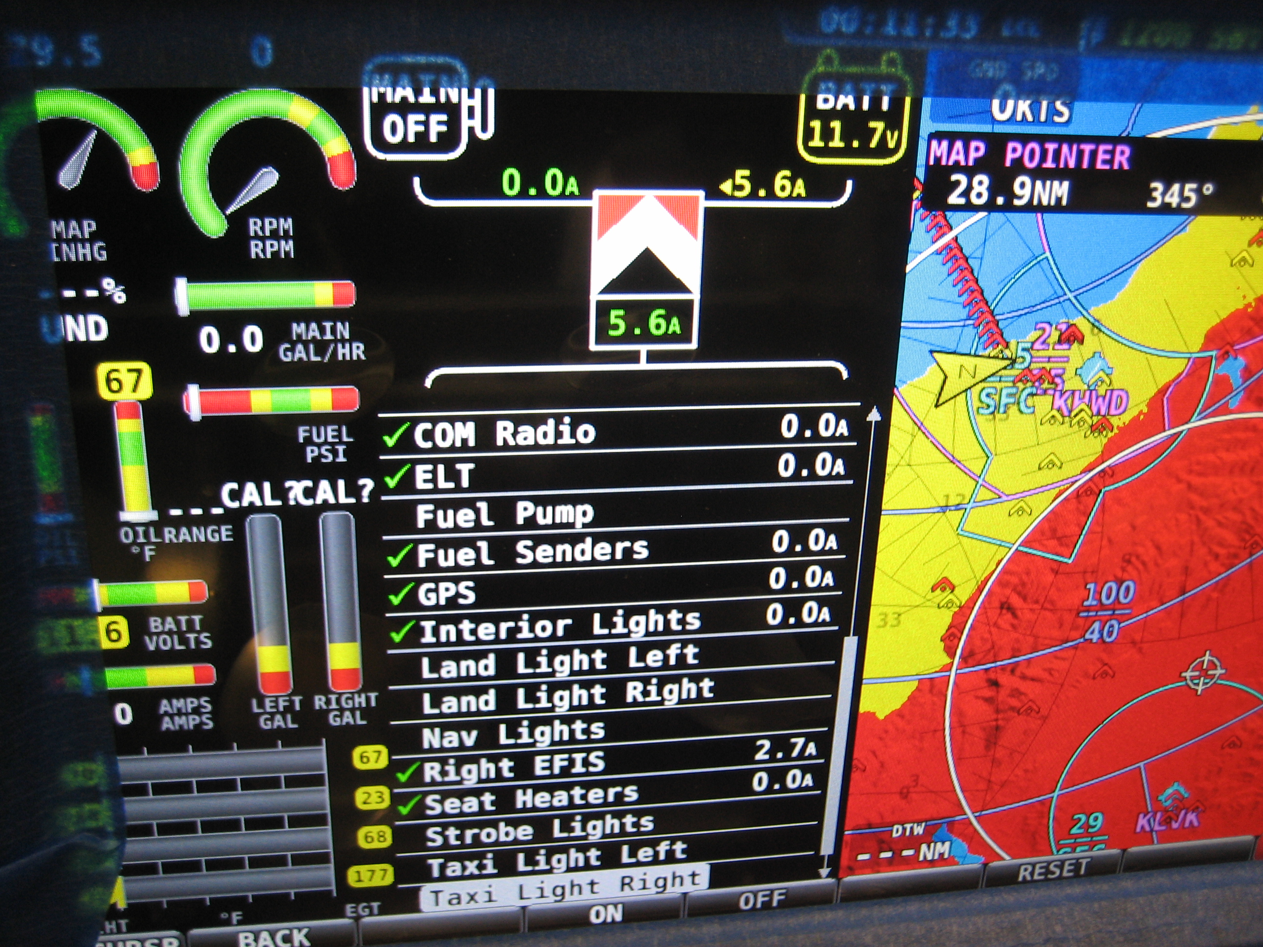
When you’re in the engine page, a new VP-X button appears that brings up the VP-X page.  At the top, you can see an electrical system diagram that shows the power flowing from the main alternator and the battery into the VP-X.  This is a little misleading though since it doesn’t include power that bypasses the VP-X such as the power to keep the master contactor closed and the power to run the electronic ignition.  I *think* this will cause this display to always show some power flowing into the battery even when the actual current flowing into the battery is zero (since the alternator will produce the extra power drawn by the master contactor and electronic ignition, but the VP-X will only show the power consumed by the devices connected to it).

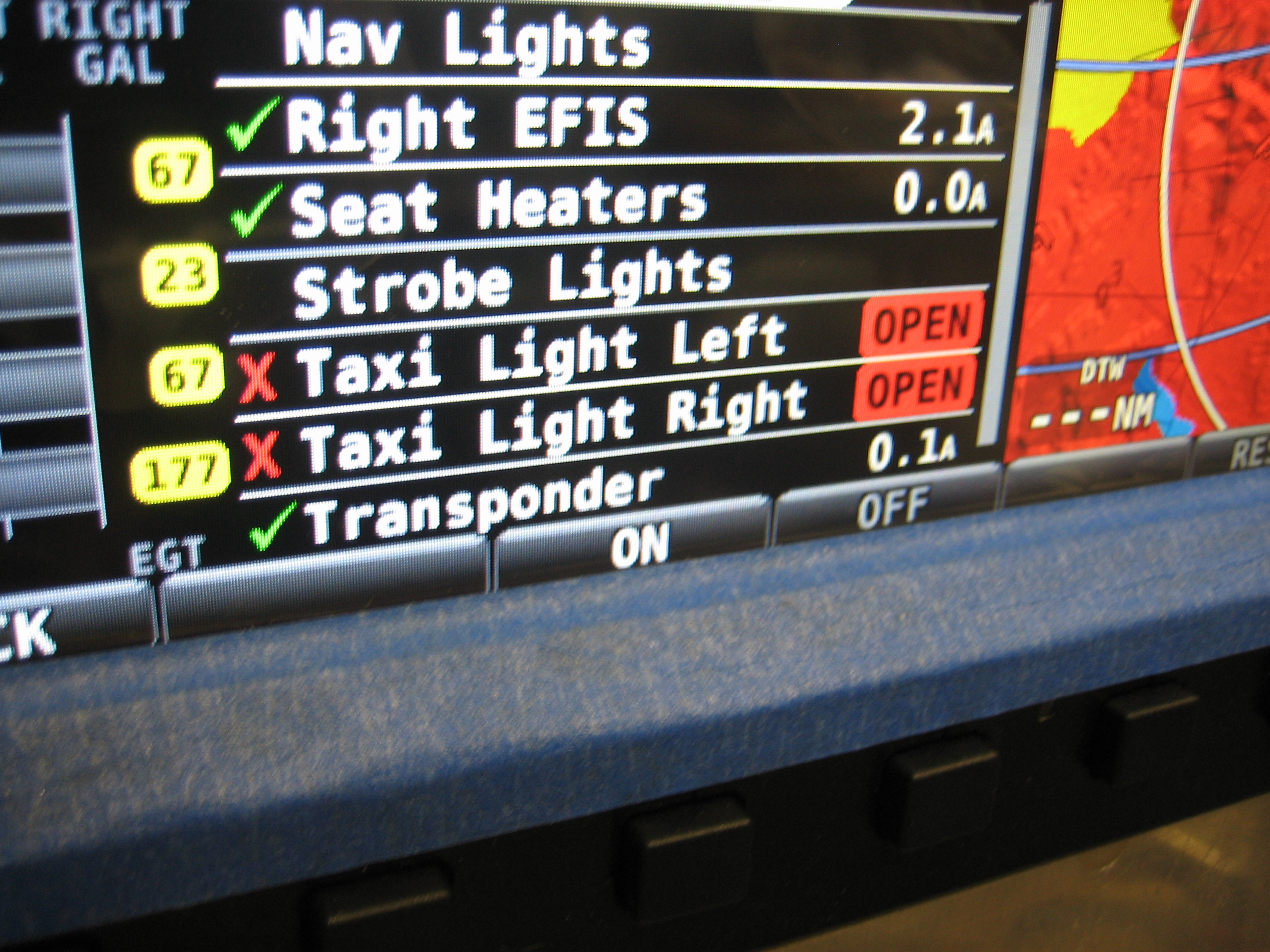
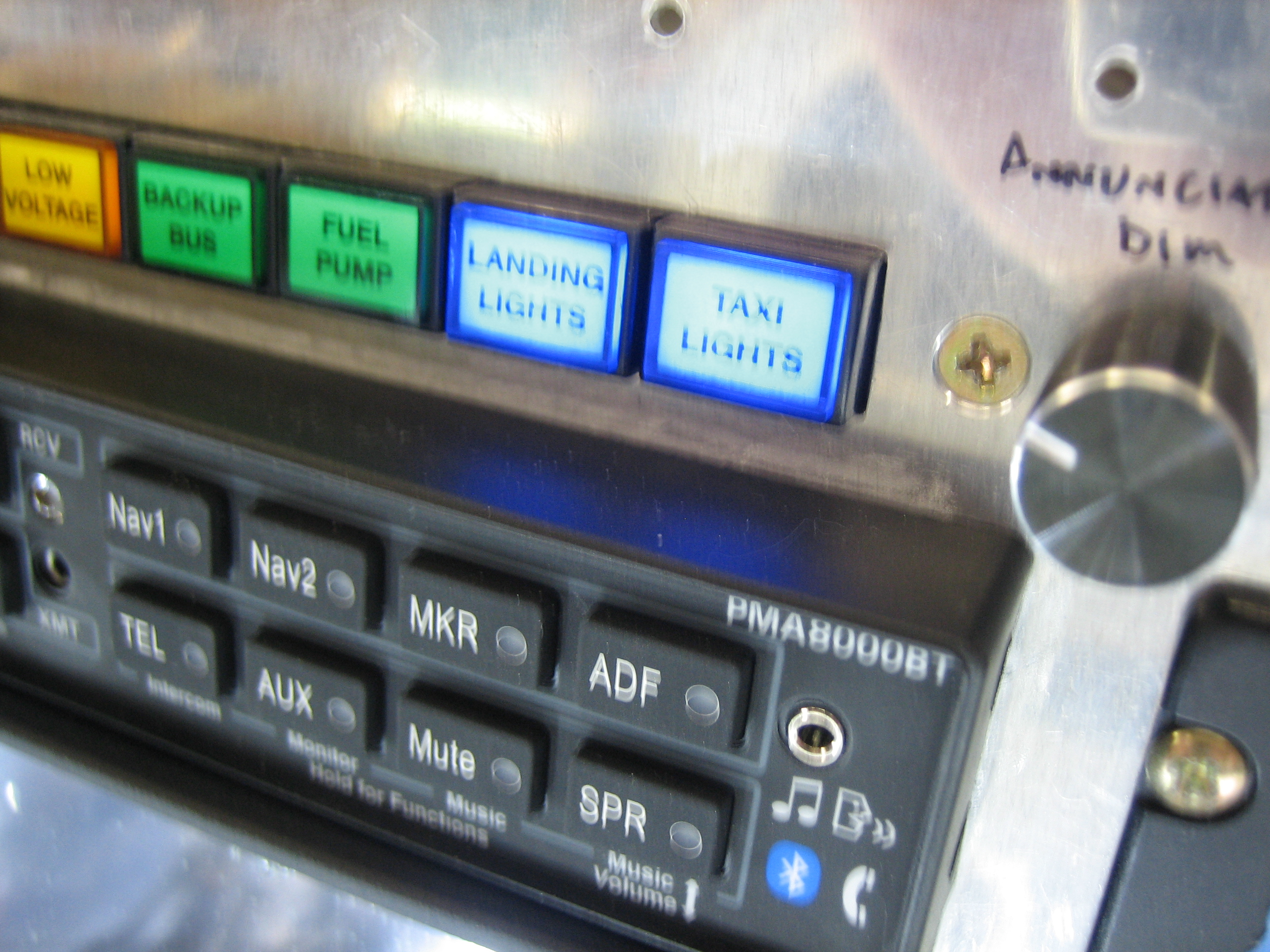
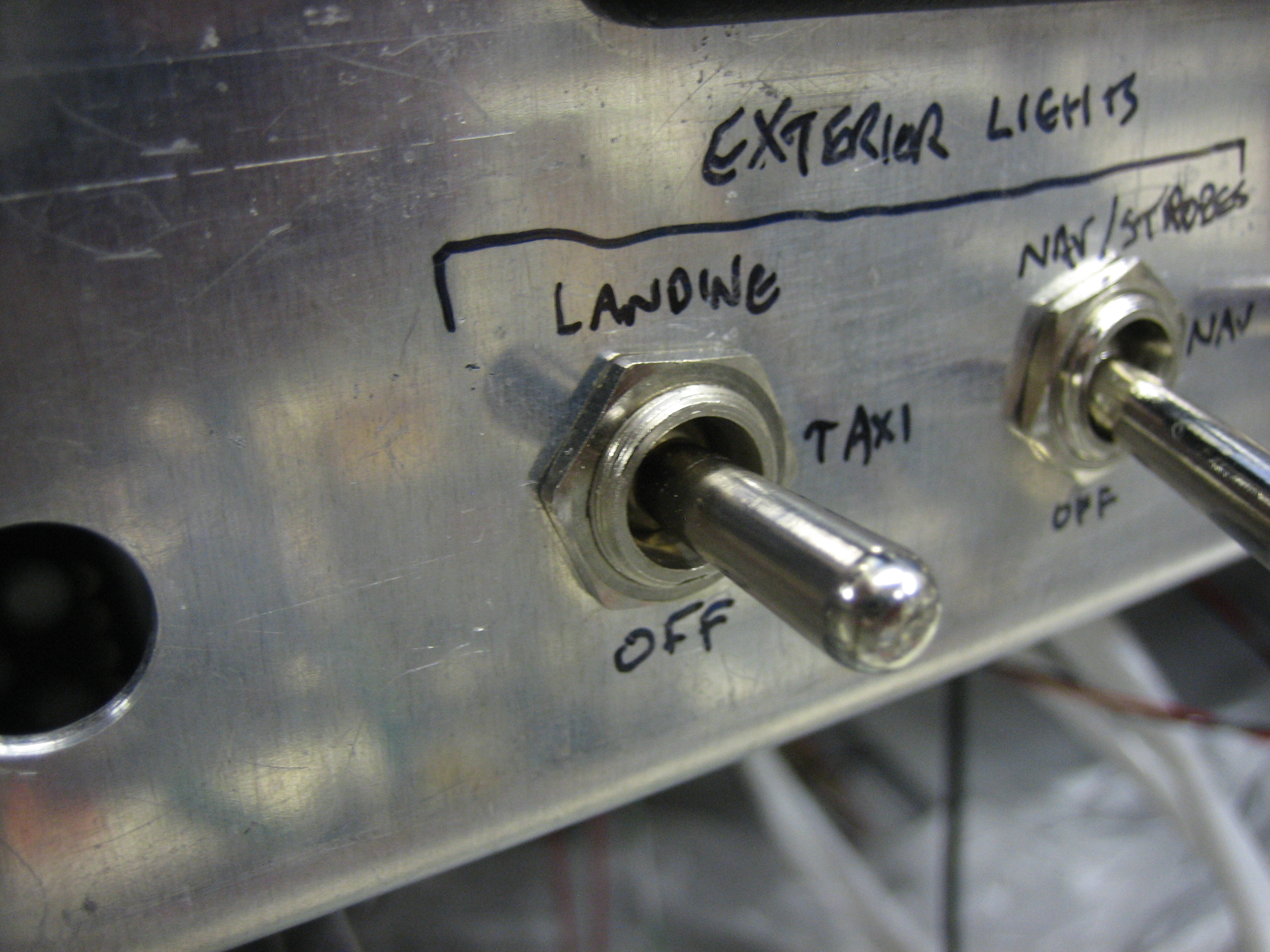
I don’t have the exterior lights hooked up, but this is a good way to test the VP-X fault detection.  I turned on the taxi lights…

…and the SkyView screen shows a VP-X fault.

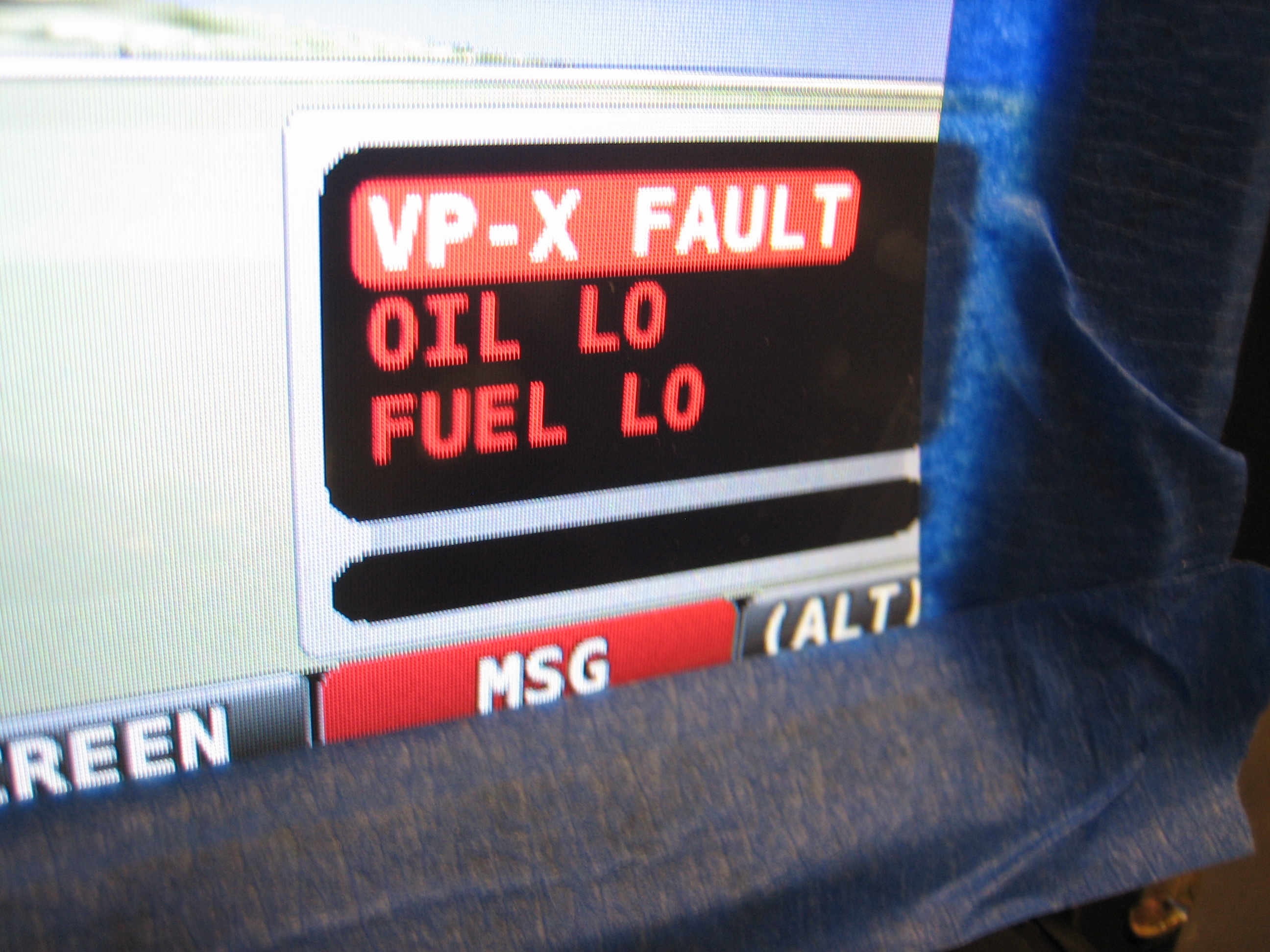
The VP-X screen on the SkyView indicates the problem is that the taxi lights aren’t drawing any current.  From here, you can scroll down and reset the fault.  The other nice thing is that device can be turned on or off or controlled directly from this page.  For example, if my fuel pump switch were to fail, I could navigate to that device here and press the “ON” button seen at the bottom of the screen to turn the device on regardless of the state of the switch.  You can even control the trim and flap motors from here.  The buttons change to “Left” and “Right”, or “Up” and “Down” as appropriate.  This is really slick, and I’m very glad I waited for the VP-X and SkyView integration.

Finished Wiring Avionics and Started Annunciators

I got an order from Aircraft Spruce with some red and blue #10 ring terminals, so I finished wiring up the GTN 635 and audio panel to the isolation diodes.  The only things left to connect here are the outgoing power wires to the TruTrak Gemini and autopilot servos.

All of the corresponding wires are hooked up to the essential bus fuse box.  There’s no fuse installed in the spot for the TruTrak Gemini since I don’t know what size it will be.

I then started wiring up the annunciator control circuit.

Push to test and the dimmer work as expected.

One of the annunciator lights to wire up is the Essential Bus light.  This pulls power off the stud on the essential bus fuse box.  The wire needs to be protected though since the essential bus fuse box is supplied with a pretty fat wire.  If I just used a bare wire from that stud to the annunciator circuit, it could melt and start a fire if it ever shorted somewhere along the wire.  To protect the wire, I could use an inline fuse, but a more reliable way is to use a fusible link.  This is basically just a short length of 26AWG wire with terminals crimped on each end.  The whole thing is covered with some silicone impregnated fiberglass sleeving.  This will be crimped to a piece of 22AWG wire that will run to the annunciator control circuit.  If this wire were to ever be shorted to ground, the 26AWG wire would melt and break before the 22AWG wire got hot enough to cause a fire.  The silicone sleeving keeps the melting 26AWG wire from causing a fire.

I also hooked up a few other lights.  First up, I connected the annunciator light to the voltage regulator.  This light flashes “Low Voltage” whenever the alternator isn’t producing power.  Second, I hooked up the oil pressure light to the oil pressure switch  This will be on whenever the master switch is on and the oil pressure is too low.  This will also serve to remind me to turn off the master switch. Finally, I hooked up the SkyView master alarm light.  This starts flashing whenever the MSG button on the display starts flashing.  It can be configured to go out or stay on after acknowledging faults that haven’t been cleared.

Misc Panel Wiring

I finished up all of the isolation diode wiring and tidied up the wires.  I then torqued all of the screws down with a torque screwdriver.

One of the last things to be wired through the isolation diodes was the autopilot servos.  I wired them up through a pullable circuit breaker and then down to the wires under the seats.  Afterward, I fired up the SkyView system and verified it could see the pitch servo.  After a quick servo firmware update, I calibrated it temporarily and then verified the autopilot controlled it correctly.

You can see here that I also wired up the hobbs meter.  The positive side is wired to the battery bus and the negative side is wired to the normally open side of the oil pressure switch.  I verified the current draw with an amp meter to determine the fuse size (1 amp is way more than enough).

Here are the three wires to the oil pressure switch.  The bottom wire is ground, the middle is the normally open contact to the hobbs switch, the top is the normally closed wire that runs to the annunciator control circuit.  When the engine is running and oil pressure is applied, the switch closes which grounds the hobbs meter and starts it running while simultaneously opening the line to the annunciator control circuit which extinguishes the oil pressure light.

I also used some 20AWG shielded wire to connect up the mag switch.  On the mag end, the center conductor is connected to the far post, while the shield is split off and wired to the ground post on the mag.  I little heat shrink keeps everything tidy.

On the switch end, the shielded wire comes in on the bottom and has a similar split,  The center conductor is also connected to a tap wire that includes a 30k? resistor.  This wire goes to the SkyView EMS to provide RPM indication.  The Lightspeed ignition also provides RPM indication, so the SkyView has redundant sources for this info.

Wired Engine Start Switch and Tested Seat Heaters

I wired up the engine start switch tonight.  The internal light illuminates when the switch is active.  Pressing it results in a satisfying clunk of the starter contactor (the starter wire is disconnected of course).

Robert at pilotlights.net has started carrying new 7A dimmers.  I ordered a couple to see if they’ll work to control the seat heaters.  The seats draw about 2.7A each, and I’ll have one of these per seat, so that gives plenty of margin.  I ran these at 2.7A for awhile, and the heat sink only gets 6-7ºF above ambient.

I pulled out my seats and hooked up the dimmers (bypassing that huge bundle of wire, connectors, relay, and switch in the lower right that come with the seats).  The dimmers work beautifully with the seats.  The voltage varies linearly with the knob position.  I had a little scare when the current through the seat bottom suddenly dropped to almost zero (~10mA).  I checked the dimmer and voltage at the seat, and everything looked good.  After a few minutes of head scratching, the current suddenly jumped back to the original value.  Apparently, the seat heaters have thermistors built into them to prevent over-heating.

Cleaned Out the Garage

It has been a long time since the garage was cleaned out thoroughly, so I pulled the plane out into the driveway and gave everything a good once over.

After pulling the plane back in the garage, I started wiring up the starter switch.  I installed all of the wires in the back of the switch, but haven’t hooked any of them up to anything.  The two red wires will be hooked to the starter switch pin on the VP-X which is only enabled when the engine isn’t running.  The black wire is the ground wire for the internal light.  The white wire with the red stripe is the switched power wire to the starter contactor.  The VP-X manual calls for a 18AWG wire for the starter, but the starter only pulls about 3.6A.  Given how little time these wires are asked to carry that current, the temperature rise in a 22AWG wire is just fine, so that is what I used.

Hooked Up ELT Audio Box and Remote

I drilled a couple of holes in the subpanel for the ELT audio box.  This emits beeps to indicate that the ELT is transmitting or when performing a self-test.  I also cut and installed modular plugs on the end of the cable and fabricated a custom short cable for the run from this box up to the remote.

Here’s the other end of the cable from the audio box.  After installing this, I put the ELT switch in the armed position and hit the test button on the remote to perform a self-test.  Initially, the ELT reported a high VSWR error which makes sense since I hadn’t yet installed the ELT antenna.  I quickly threw a BNC connector on the end of the antenna cable and connected the antenna.  Re-running the self-test indicated that all systems were functioning properly.  I still need to confirm that the ELT is properly receiving position data from the GTN, but I need to fabricate a small test circuit to do that.

Wired Electronic Ignition and Tested ELT

I received another order from Aircraft Spruce with some 18AWG shielded wire.  The piece that came with the electronic ignition wasn’t long enough to run from the unit to the switch, then to the breaker, and finally to the battery bus.  I used a solder sleeve to join the shields of two pieces and then connected their center conductors to the NO side of a 1-3 switch.

From the switch, the wire runs to the breaker where a similar connection is made.

The center conductor of the shielded wire is connected to the battery bus (the upper right fuse here).  Another solder sleeve is used to connect an 18AWG black wire to the shield.  The installation manual specifies that this should be directly connected to the battery, but I’m trying to limit unprotected wires in the aircraft as much as possible.  Connecting this here adds only a couple of connections over the recommended wiring method, and these are very high-reliability connections.

That black wire then runs to the ground block.  I drilled a hole through the firewall to anchor the other end of the ground block and attached the wire there.  I doubt this is significantly more reliable than one of the fast-on connectors, but it’s about as reliable a connection as you can make short of connecting it directly to the battery ground terminal.

I had a little more energy, so I quickly fabricated the ELT data verification circuit and hooked it up to the wire that I left sticking out of the ELT connector.  I fired up the avionics and verified that after the GTN had acquired a GPS fix, the light started flashing about once a second to indicate that the ELT was receiving valid position data.

Finished Annunciator Lights (Almost)

I wired up the remaining annunciator lights (other than the “Canopy Unsafe” light).  The final three were the landing and taxi lights as well as the fuel pump.  Unfortunately, this unveiled a flaw in the annunciator control circuit I designed.  Basically, for annunciator lights that are triggered high, I was assuming the transistor base voltage would be shed through the load when the load was turned off.  The problem is that for certain types of loads (e.g. LED lights), the load resistance is pretty high at low voltages.  This has the effect of causing the transistor base voltage to fall pretty slowly after the load is turned off, which causes the annunciator light to dim slowly.  I really need to couple the base and emitter with a resistor to provide an alternate path for the base voltage to drain.  I’ll have to redesign the circuit and have new PCBs made.

Fabricated Headset Jack Brackets and Worked on Pilot Stick Wiring Bundle

I fabricated the headset jack brackets from some 0.040″ bent sheet.  These were cut from the original engine control bracket that Van’s includes in the kit.  I drilled the holes 1″ apart and drill three staggered holes to mount the brackets to the bulkheads.  Here’s the copilot’s bracket.

And here’s the pilot’s bracket.  These are mounted high enough that they’ll never accidentally be kicked or bumped, but low enough that you can still lean over just a bit to see when plugging in the headset.

I then wired up the pilot’s jacks.  The mic jack is on the top and includes two extra wires that are routed to the pilot’s push-to-talk button.  I then routed those two wires back to the pilot’s stick.

There is just over 1/4″ of clearance between the plugs and the face of the bulkhead.  The interior side panels will mount to this face and are approximately 1/8″ thick.  This will keep the plugs fairly tight against the side panels without causing them to rub against it.

Here’s how I ended up deciding to secure the stick wiring.  The bundle exits the bottom of the stick between the bearings and then wraps around the end and back up the side where it is anchored with a couple of zip ties.  It then curves over and is anchored to the adjacent rib with an adel clamp.

Because the bundle curves away from the stick pretty much right at the pivot point, the length hardly changes as the stick is moved.  The position with the least slack is with the stick in the aft left position.

Moving the stick to the fore right position creates the most slack in the bundle.  I’m really happy with this arrangement as the bundle has very little flex and has no chance of interfering with the control stick or aileron trim.

Finished Pilot Stick Wiring

I finished wiring up the pilot’s stick grip tonight.  The bundle from the stick terminates at the connector on the left so that the stick can be removed without having to disassemble any of the wiring.

In the next bay to the right, the ground wires split off and are grounded to the rib with a #8 screw since these are just ground sense wires.  I cleaned off the primer and used some Noalox anti-oxidant compound to ensure a good ground.  The yellow wires from the autopilot servos are tied together here and connected to ground through a 5kΩ resistor which allows the SkyView system to detect a broken autopilot disconnect wire.  They can also be shorted directly to ground through the CWS button on the stick which triggers the CWS and autopilot disconnect functionality.  Six of the wires (four trim wires and PTT wires) proceed from here up behind the subpanel.

With the final four connections made on the J2 connector, I installed the connector shells on J1 and J2.  Finally, I fired up the avionics and verified that I can transmit on the radio, control the autopilot, and drive the trim.  I did notice one oddity though.  When I first tried running the trim with the coolie hat, the aileron trim ran backward from the way it should have.  I hooked up the laptop and double checked that the coolie hat was wired up correctly and it was.  Reversing the motor addressed this problem, but created another.  When I go to the VP-X page on the SkyView and scroll to the roll trim device, the Left and Right buttons at the bottom of the screen now are reversed.  I also configured the trim widget on the engine control page and noticed another oddity, when I trim all the way to the right, the arrow moves all the way to the left.  Looks like it’s time to contact Dynon again.