Wing and Tail Light Wiring

Along with the shielded 3-conductor wire for the ELT, I received the wire for the wing and tail lights.  I’m going with the Aveo Engineering AveoMaxx 6-in-1 lights.  I bought color coded wire to match the AveoMaxx wire colors (except for 18AWG orange which I couldn’t find).  I strung most of the wires to just forward of the spar.  I can’t run them all the way forward just yet since the forward top skin is on while fitting the cowl.  The remainder of the wire is coiled up in the tail and wing root area.

More Wing and Tail Light Wiring

I finished up the ground wire with the exception of the bit of 14AWG from under the seat up to the firewall.  I’ve got 18AWG ground wires going to each of the two wing tips and the tail.  These are tied together with the 14AWG that will ground at the firewall.  This saves me having to run all three ground wires all the way forward.  I’ve done the exact same connection for the strobe and nav power wires from the VP-X.

Finished Exterior Lighting Ground

I got an order from Aircraft Spruce today with some 14AWG black wire for the ground wire that ties the tail and wing wires together and runs up to the firewall.

The adhesive zip-tie base that attached the end of the tailcone conduit had fallen off, so scuffed everything up and used some E6000 adhesive to anchor the base to the side wall.  There is no way this is coming off now.

More Cowl Work and Pitot/Static/AOA Plumbing

I spent a little time earlier today working on the cowl.  I made the side cuts, then did a bunch more sanding to get the fit as nice as I can.

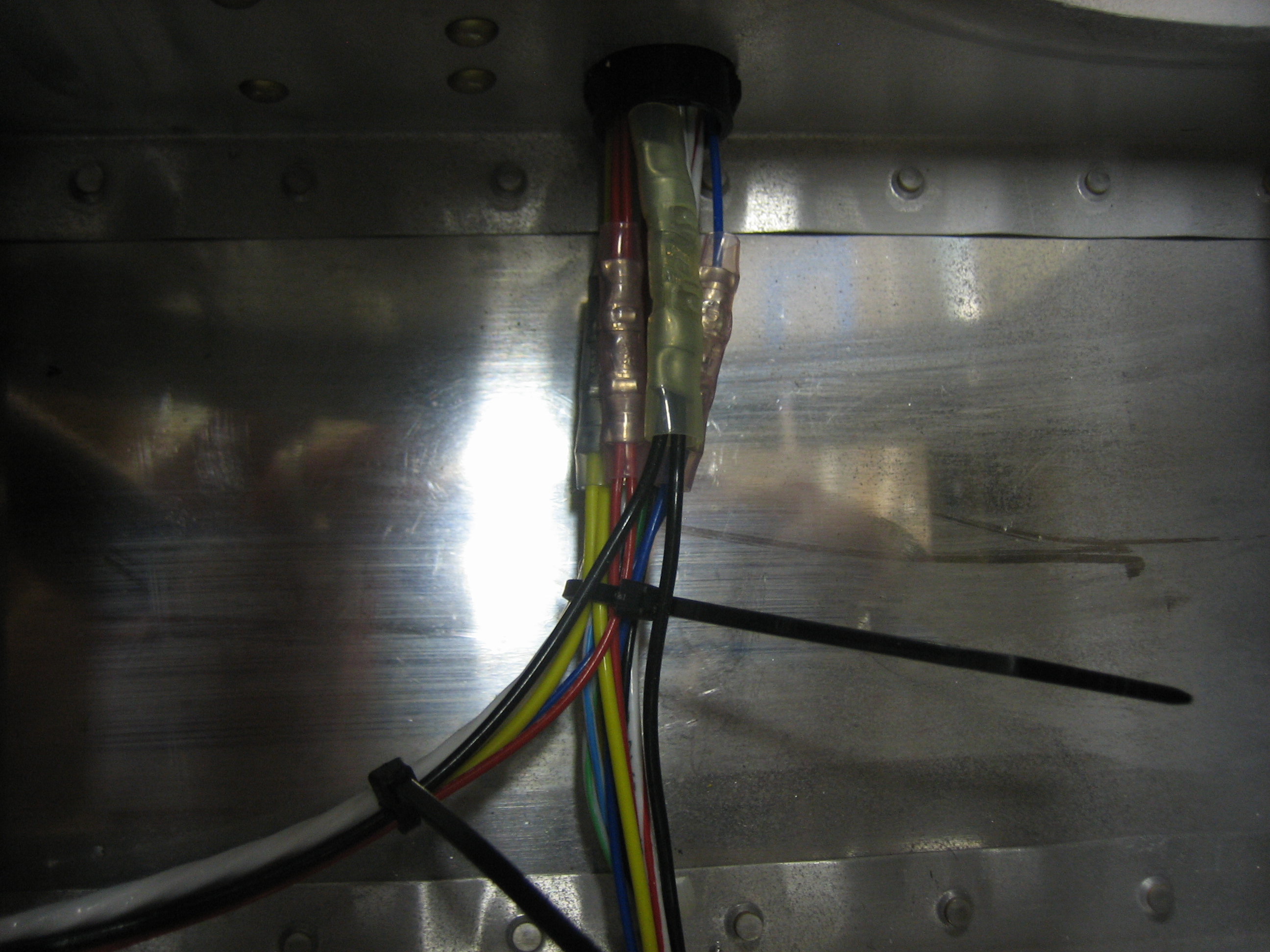
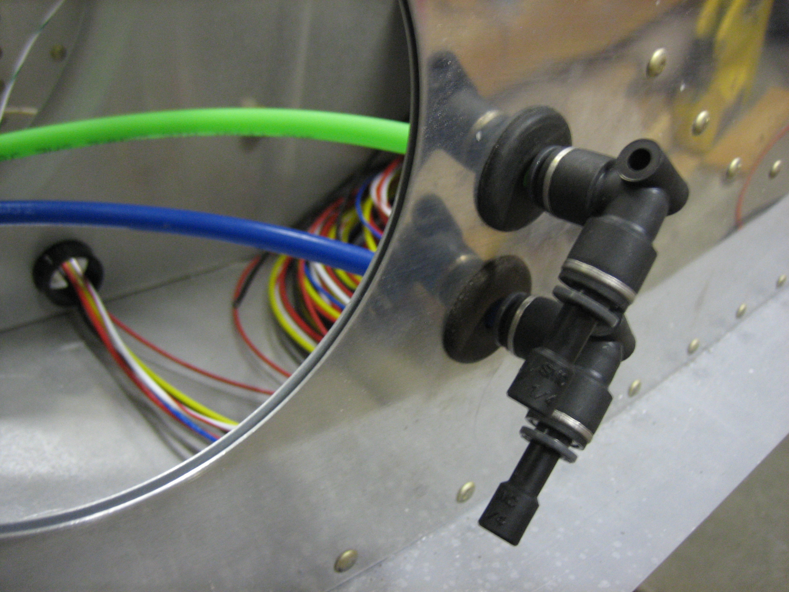
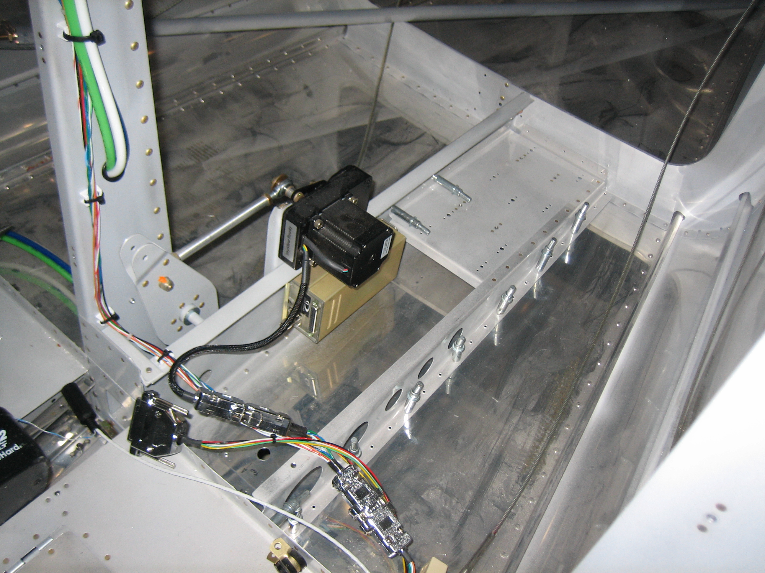
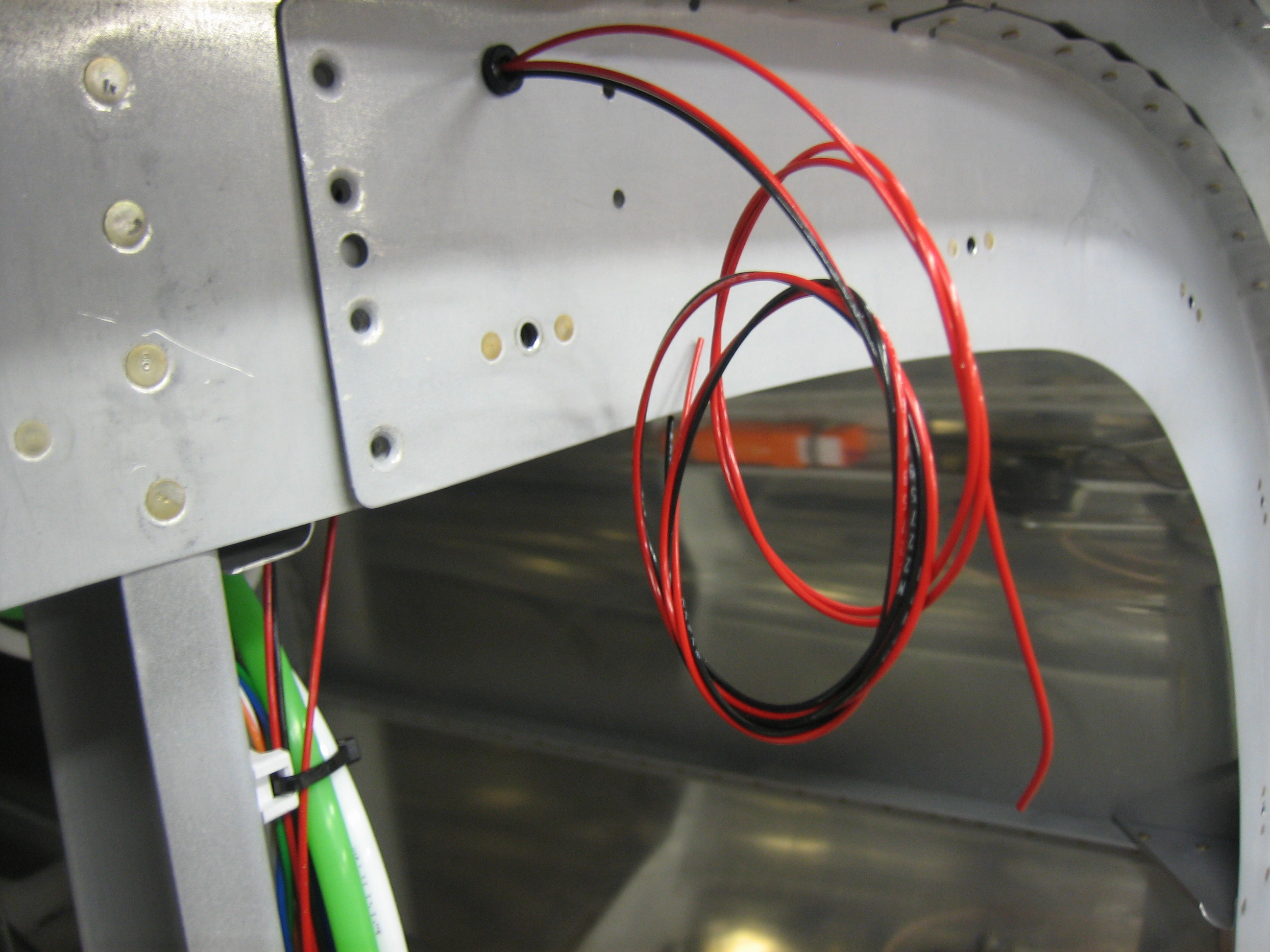
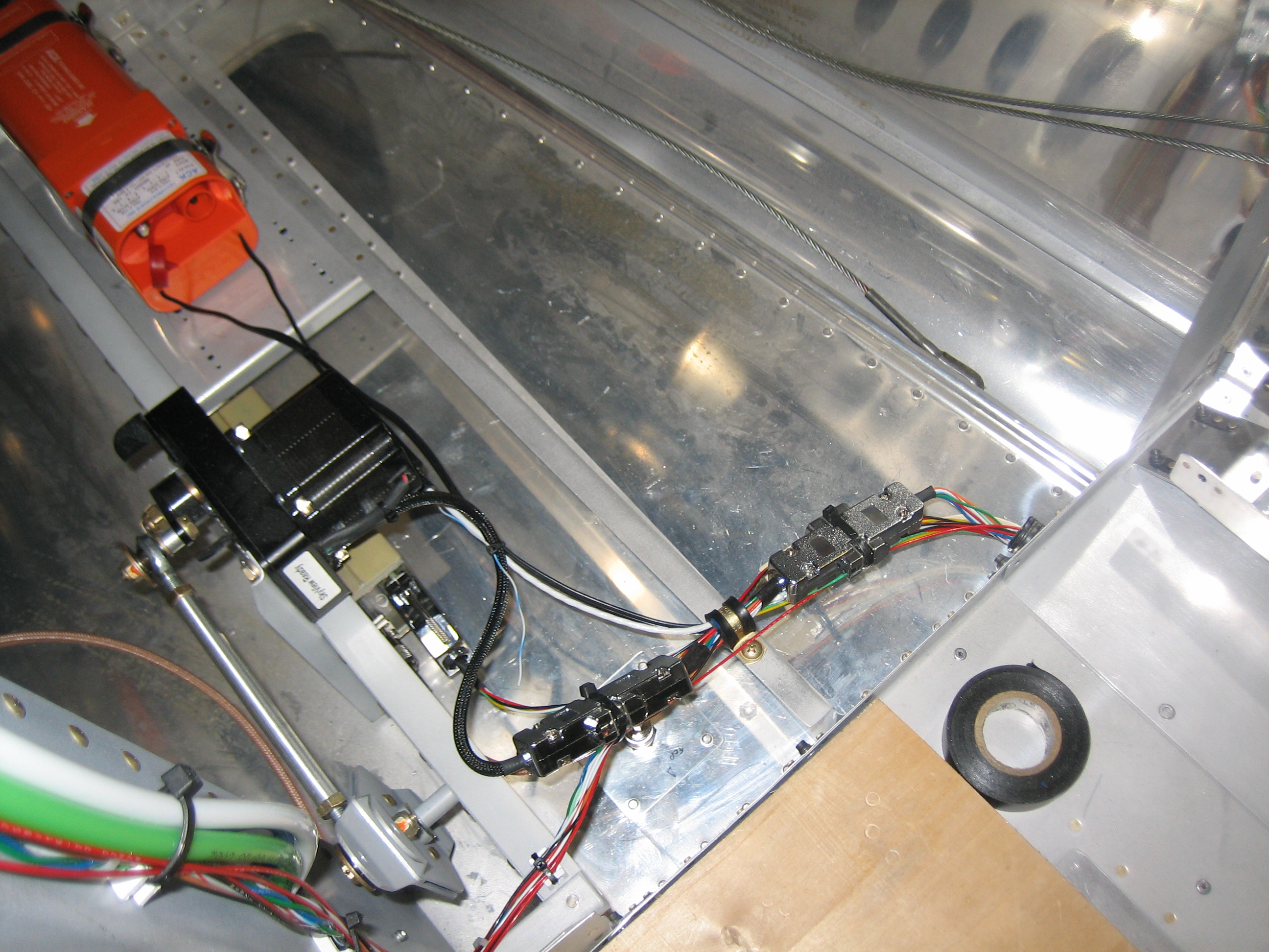
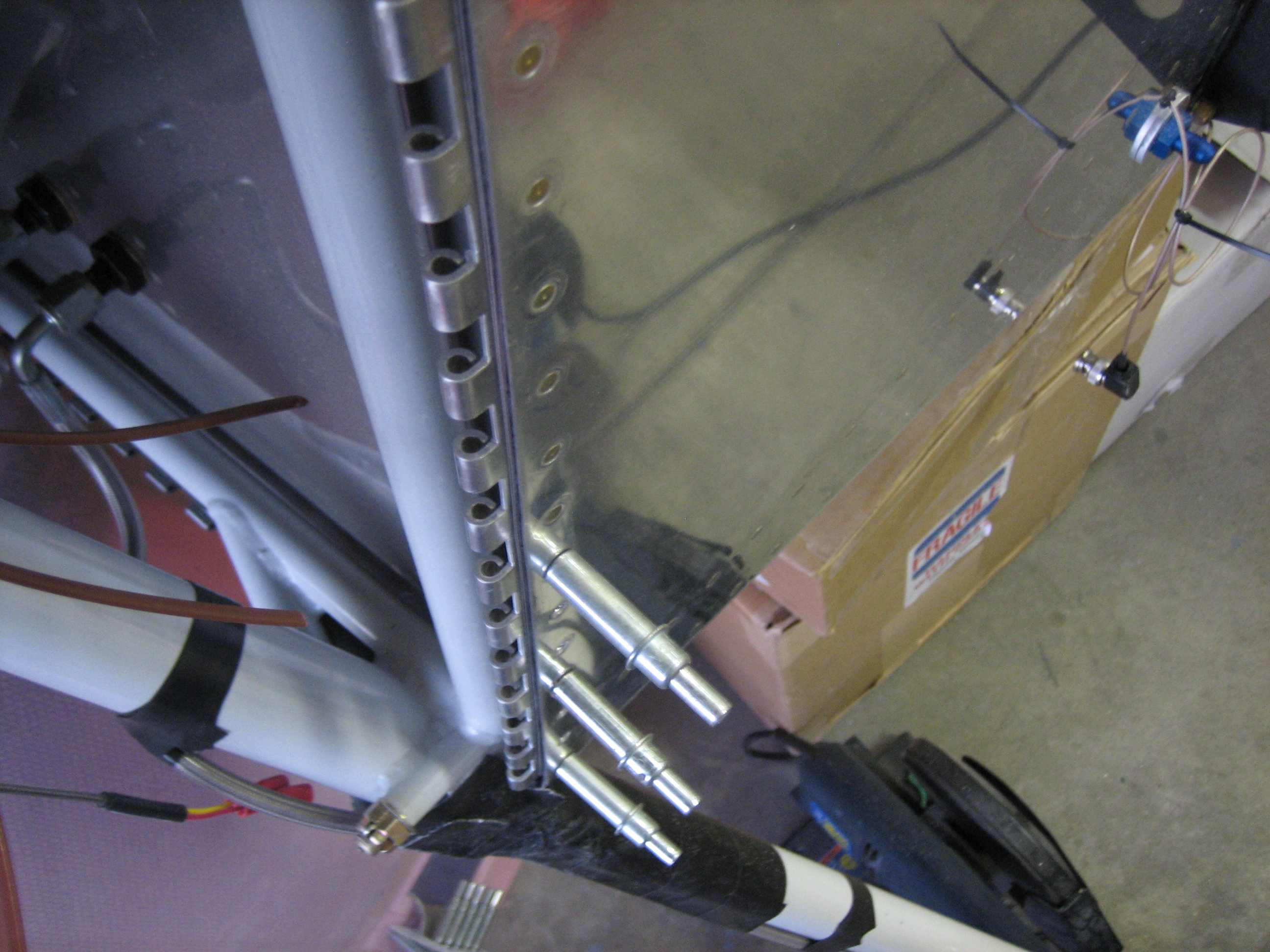
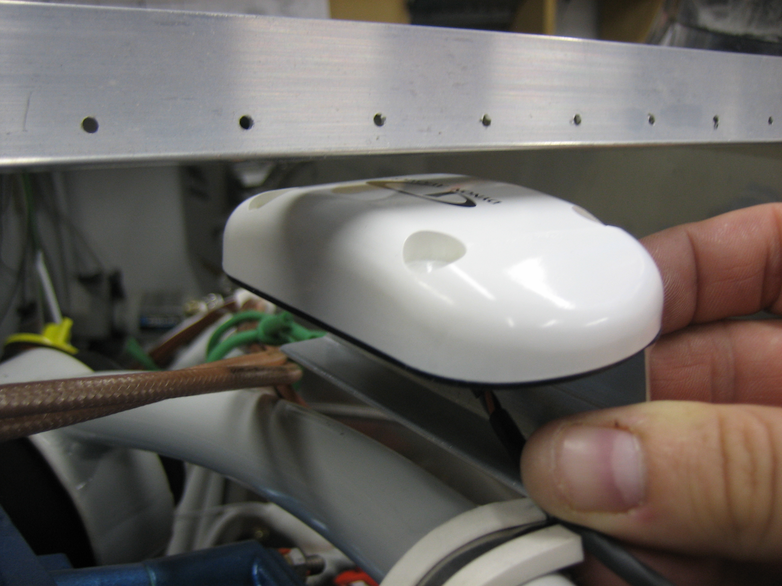
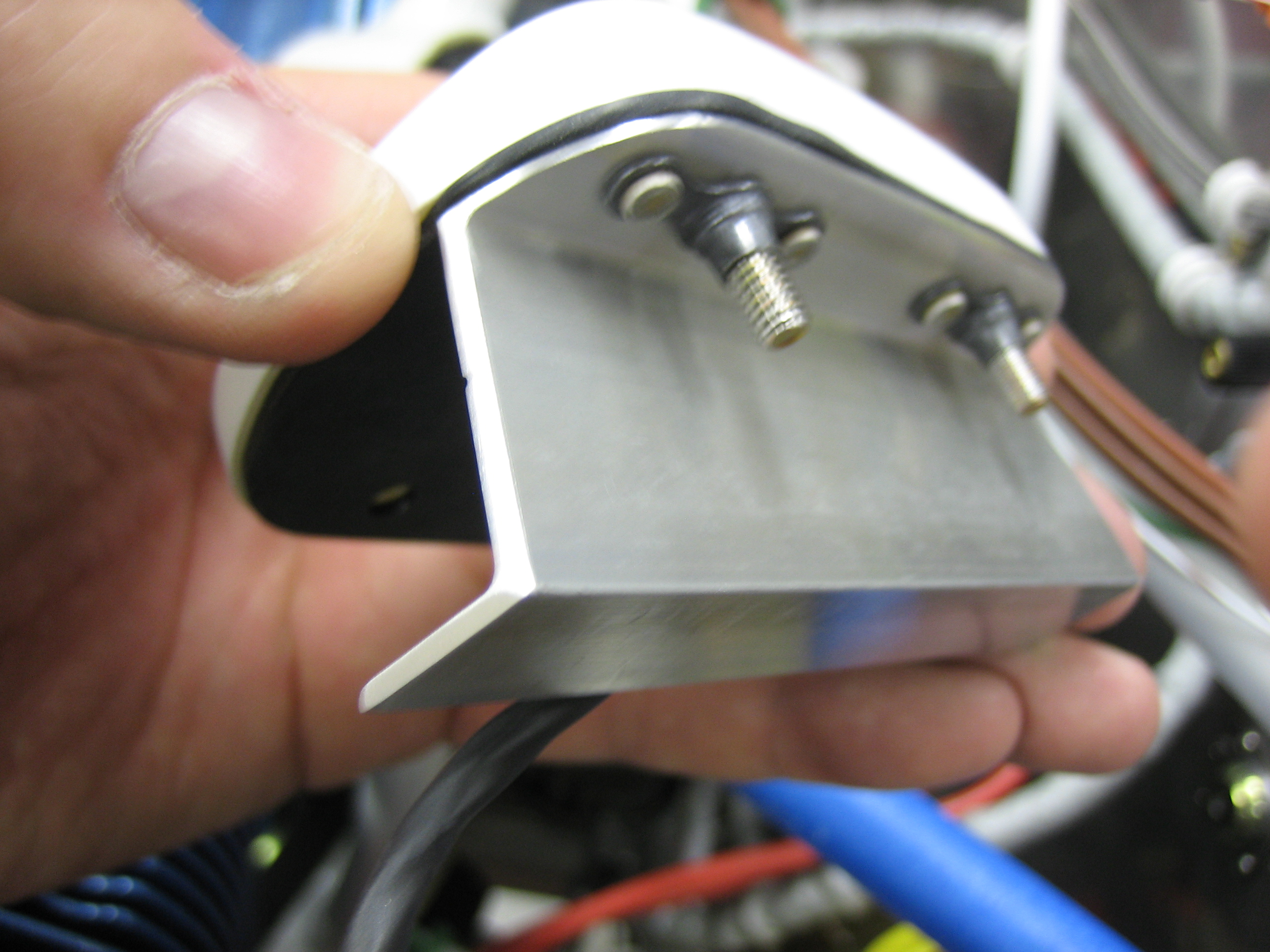
Afterward, I decided to do the pitot/static/AOA plumbing.  This is where the pitot (green) and AOA (blue) lines will go into the fuselage.  The lines from the wings will connect to these connectors.

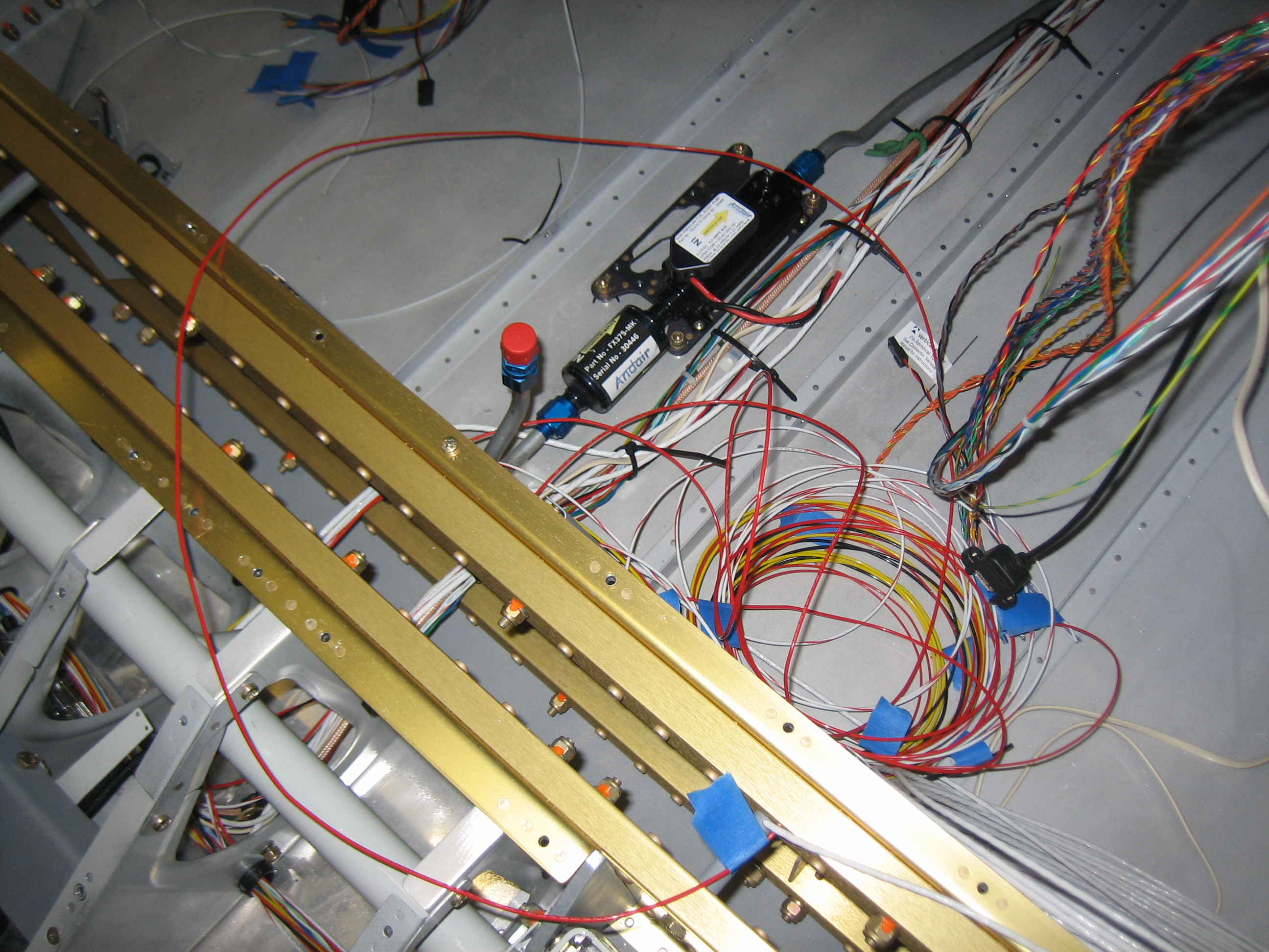
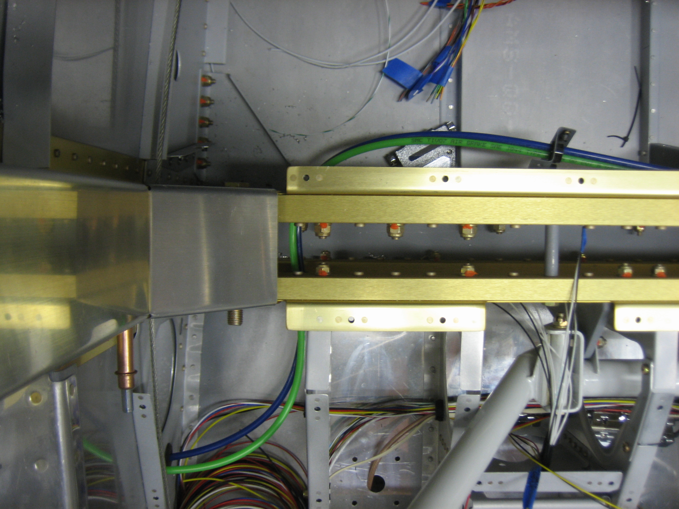
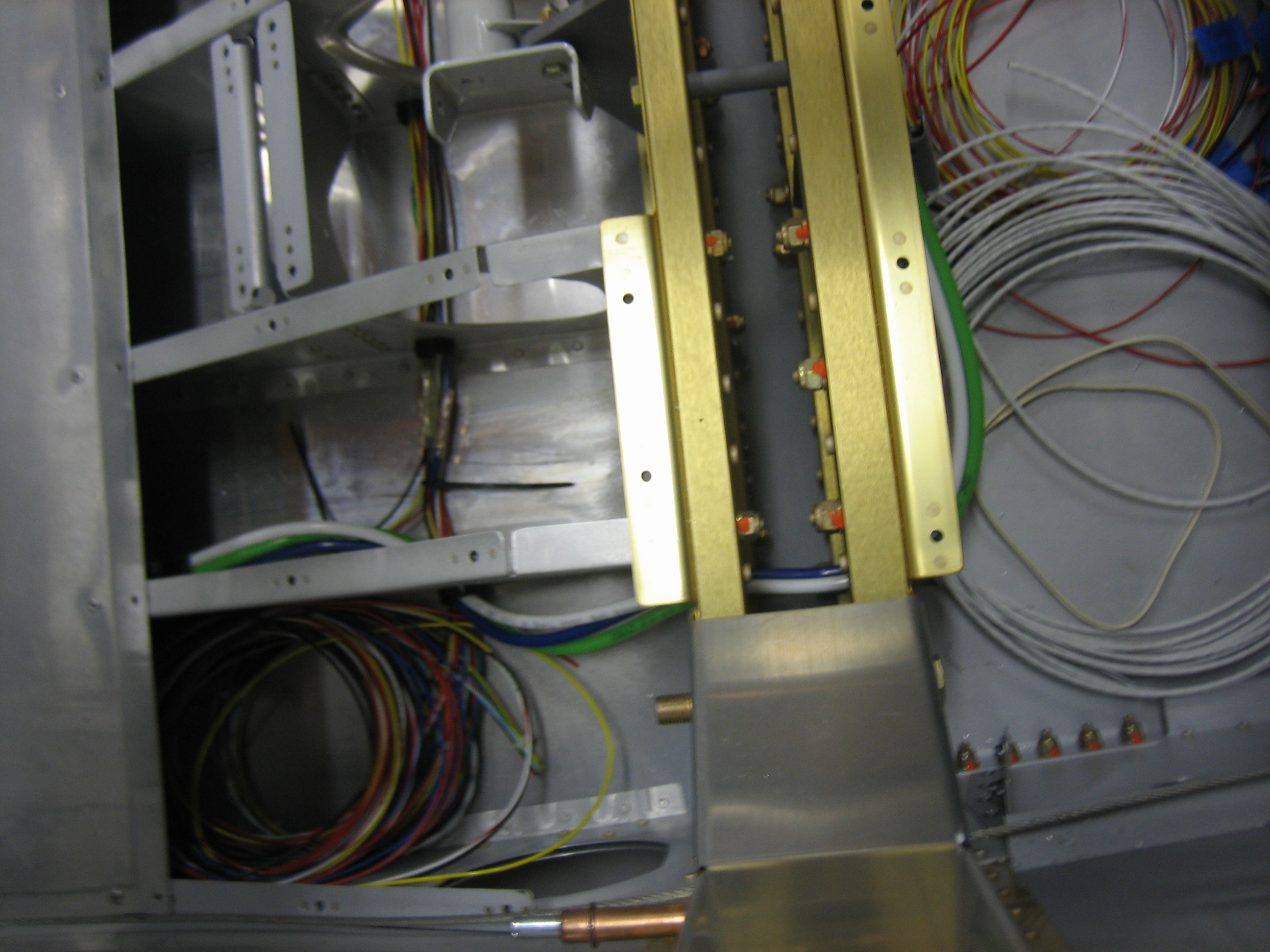
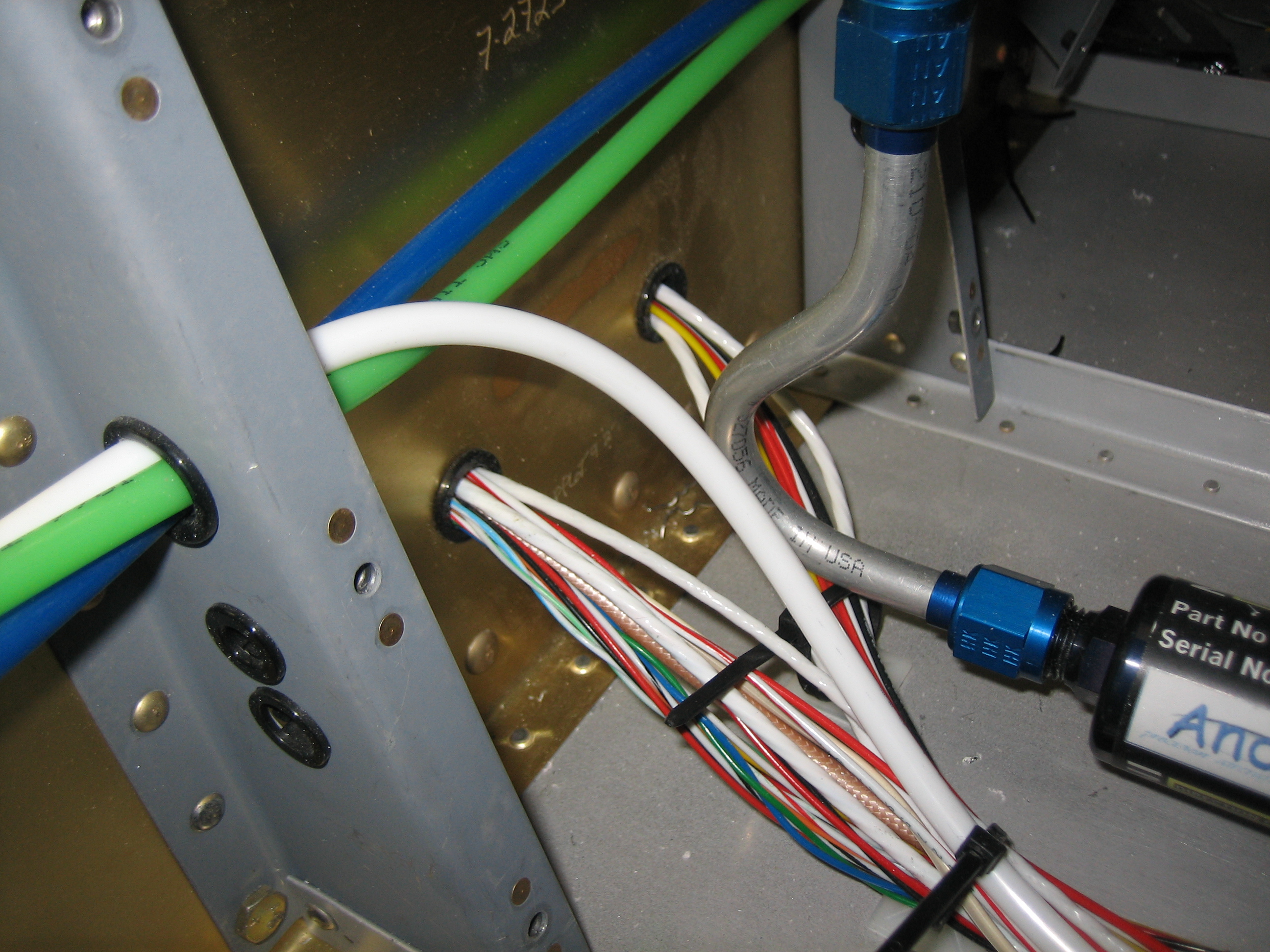
The pitot and AOA lines run forward of the spar and then across the fuselage.

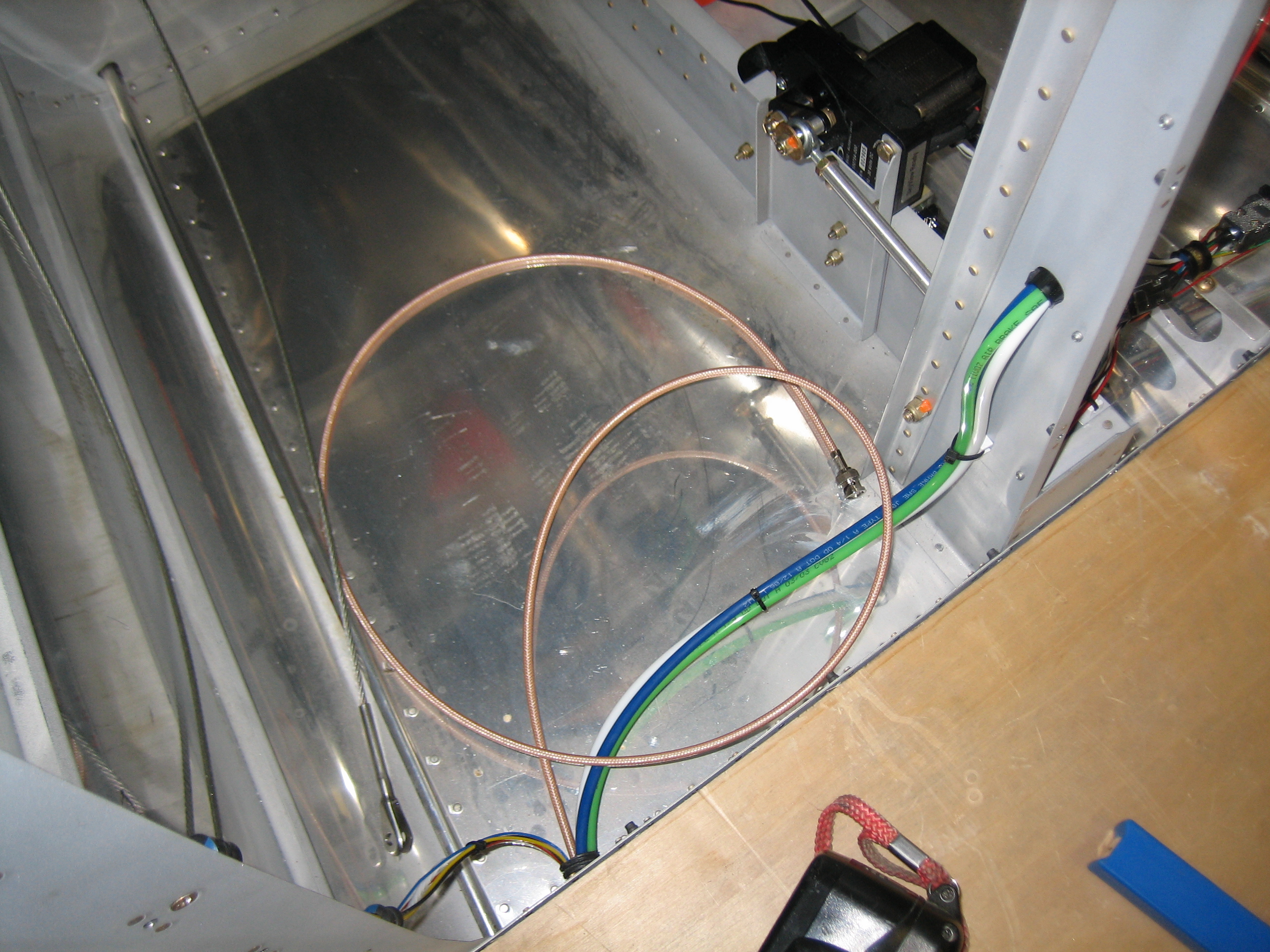
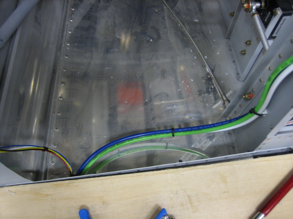
They then run back through the spar along with the static tube (white).  This may seem like a somewhat circuitous route, but the left under-seat conduit is pretty full, so I needed to run the lines through the right under-seat conduit.  Unfortunately, there’s no good path across the fuselage aft of the spar for lines this large.  I could have drilled more holes in the seat ribs and installed snap bushings, but that’s a real pain in the ass at this stage of construction.

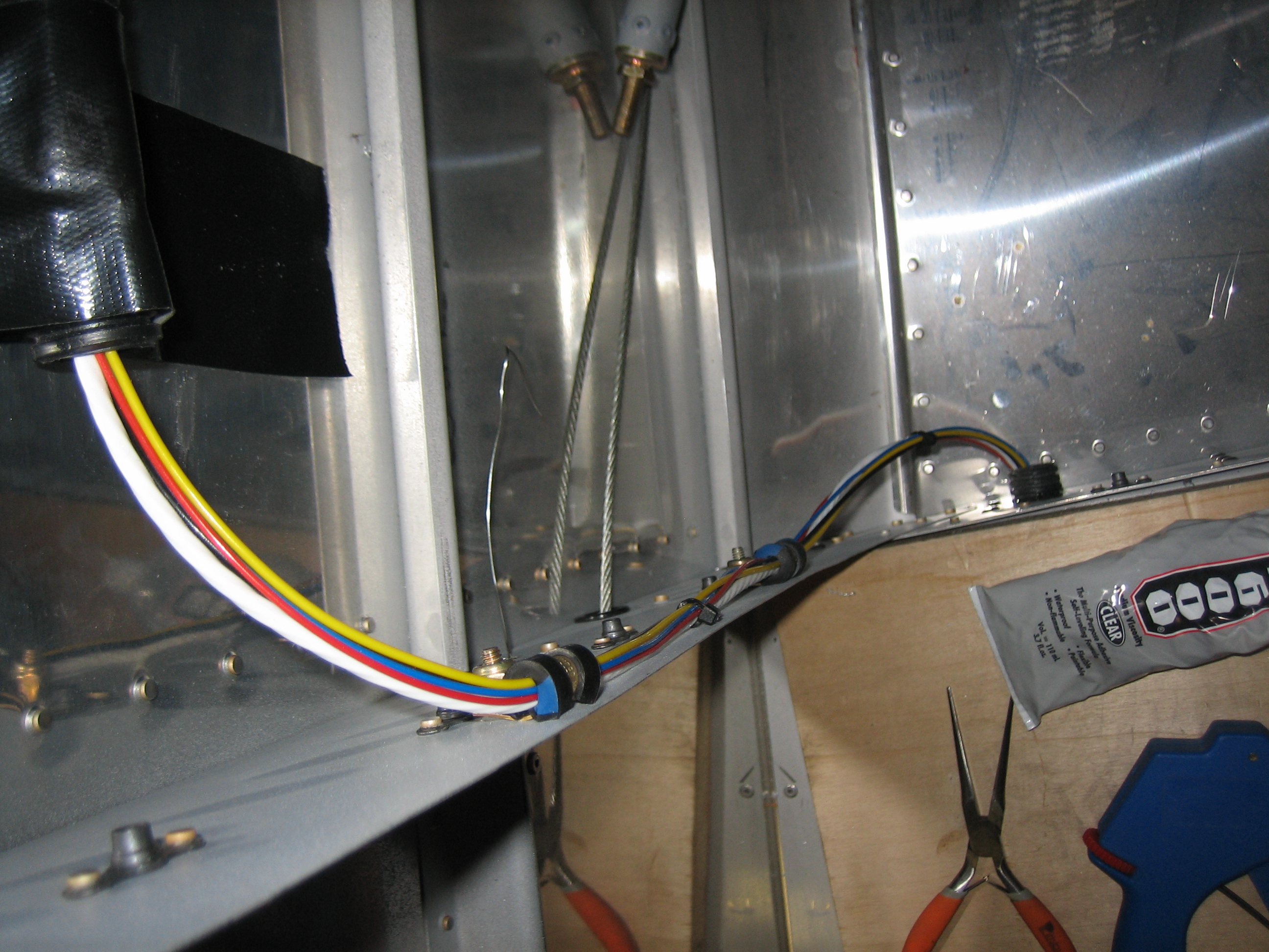
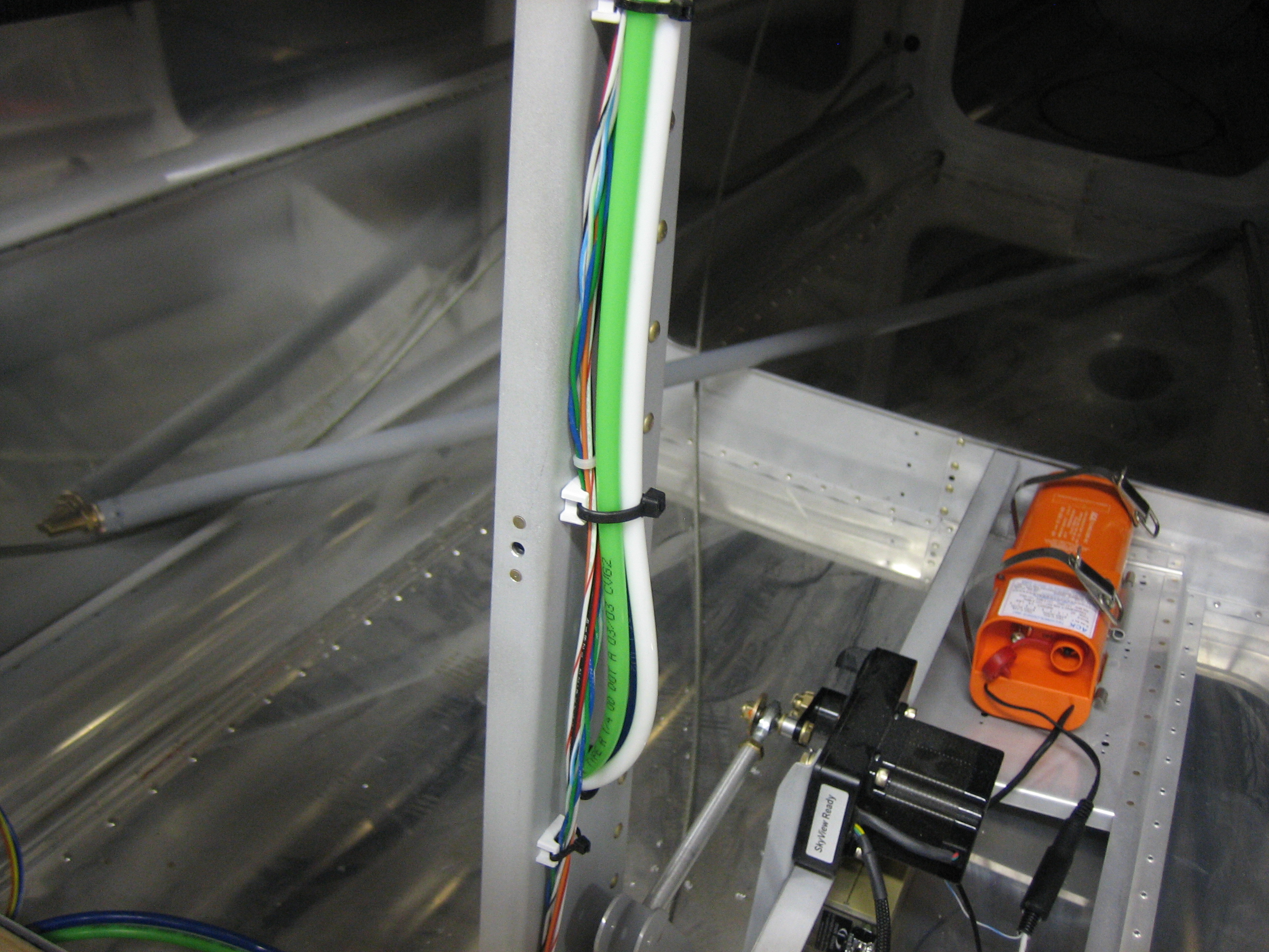
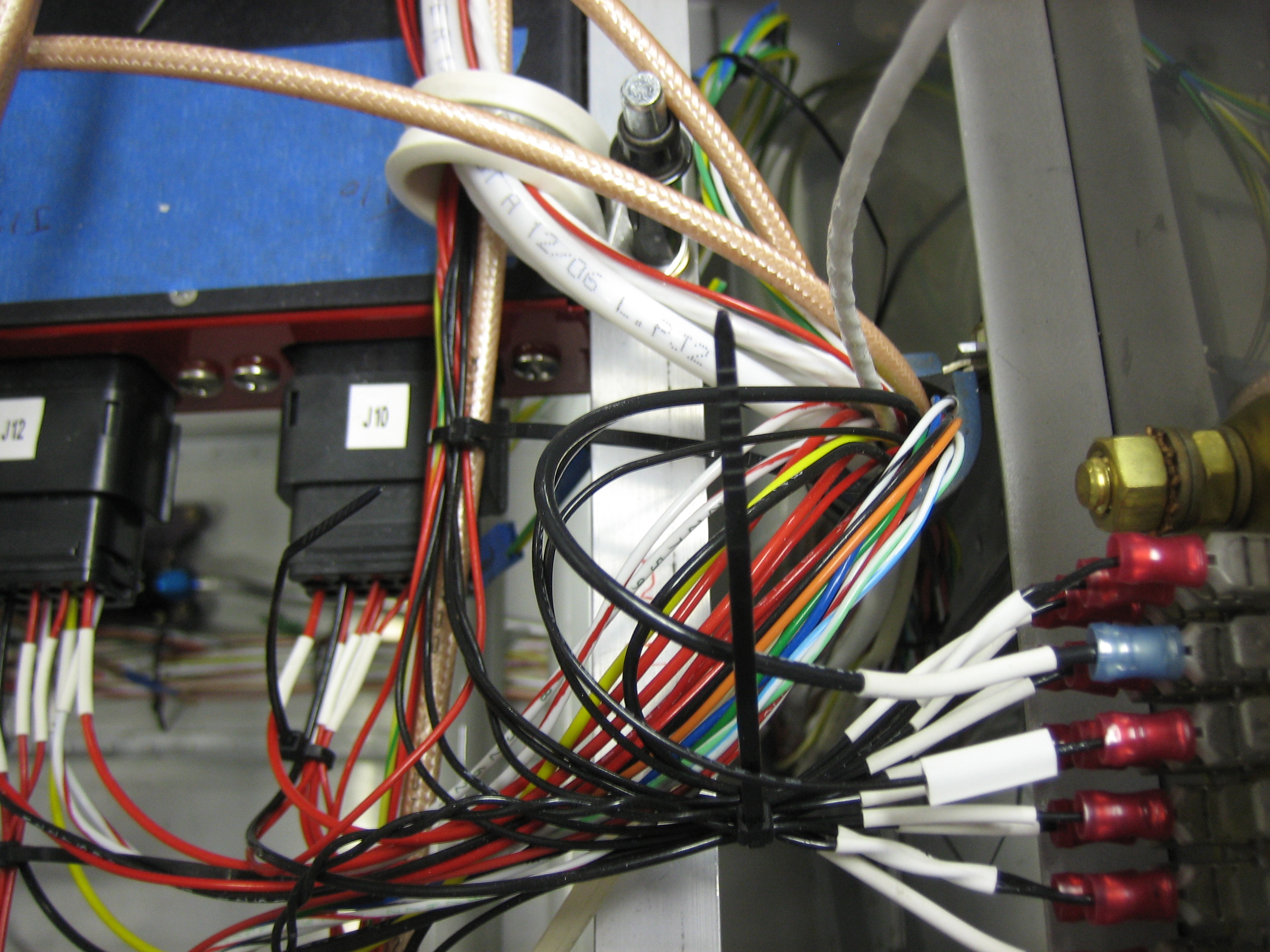
The pitot and static lines needs to run up to the instrument panel to connect to the backup EFIS and alt static valve.

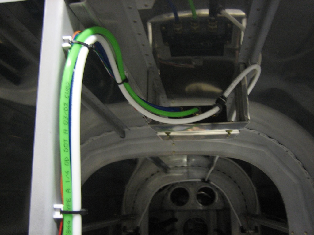
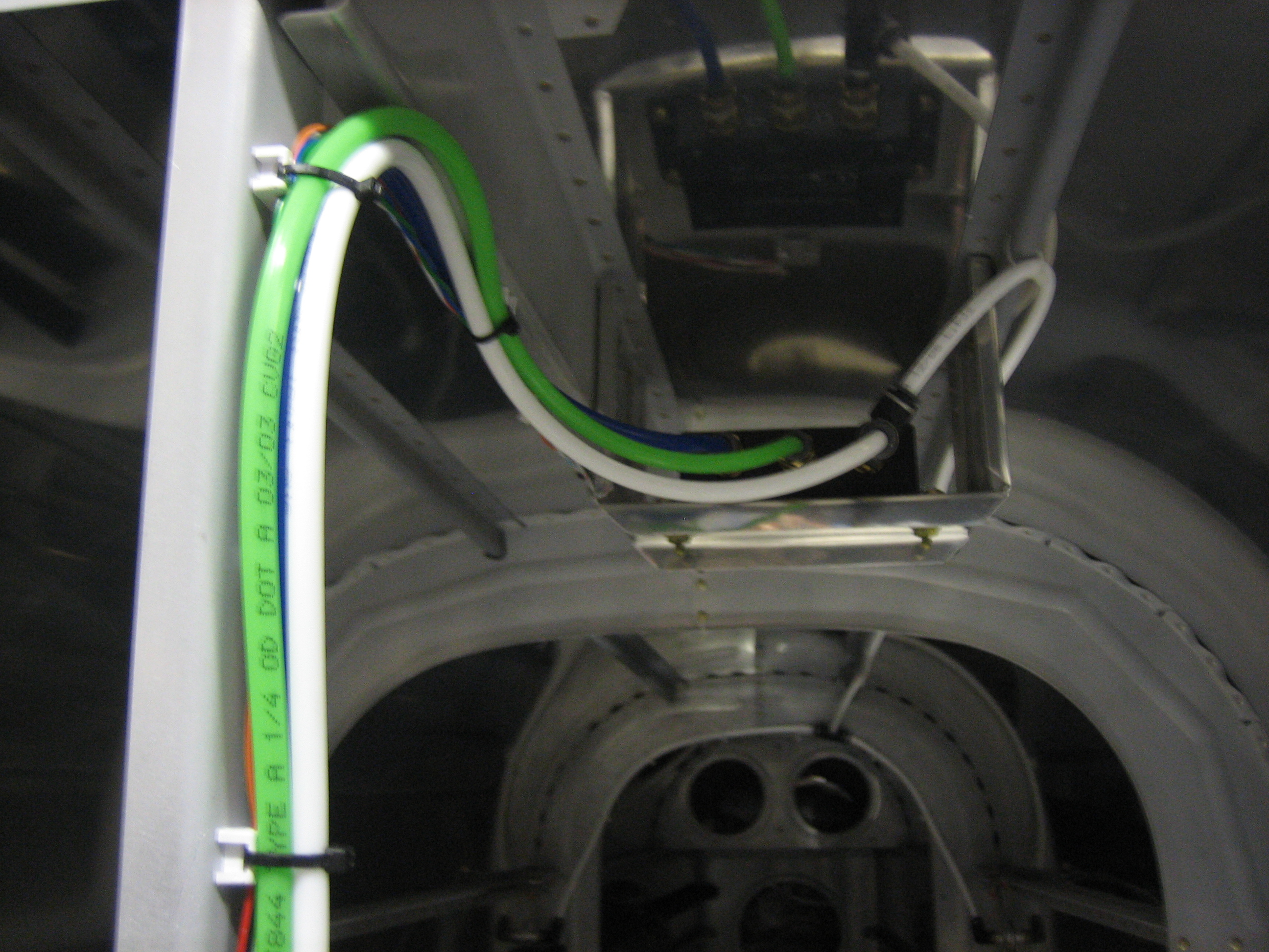
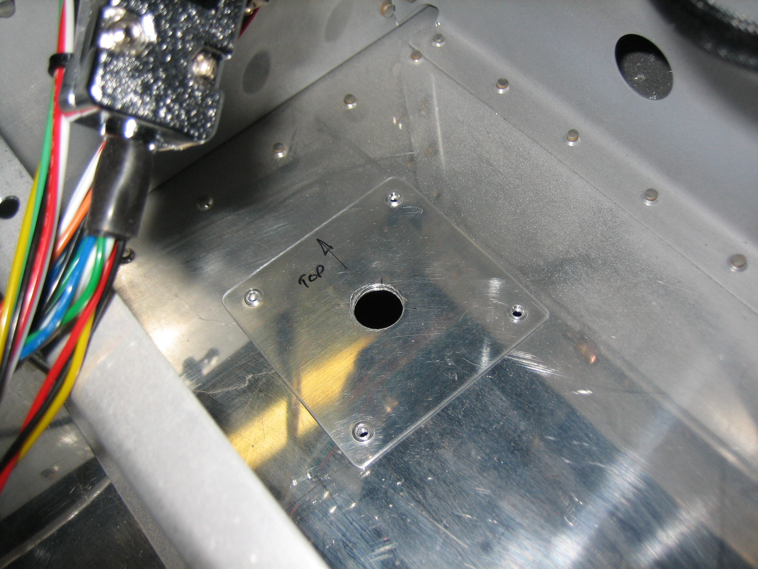
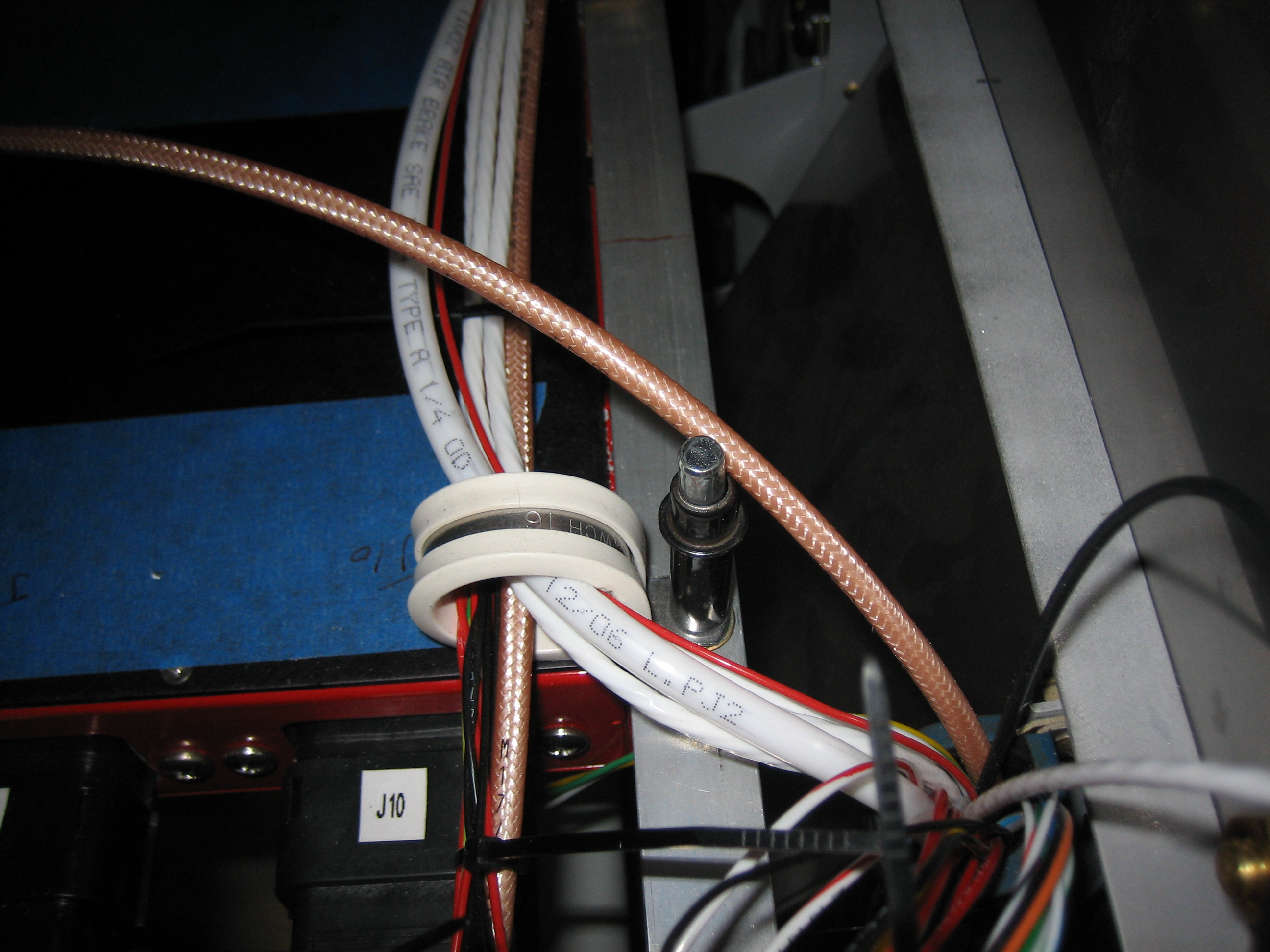
The lines come out of the right under-seat conduit and then run up the center post.

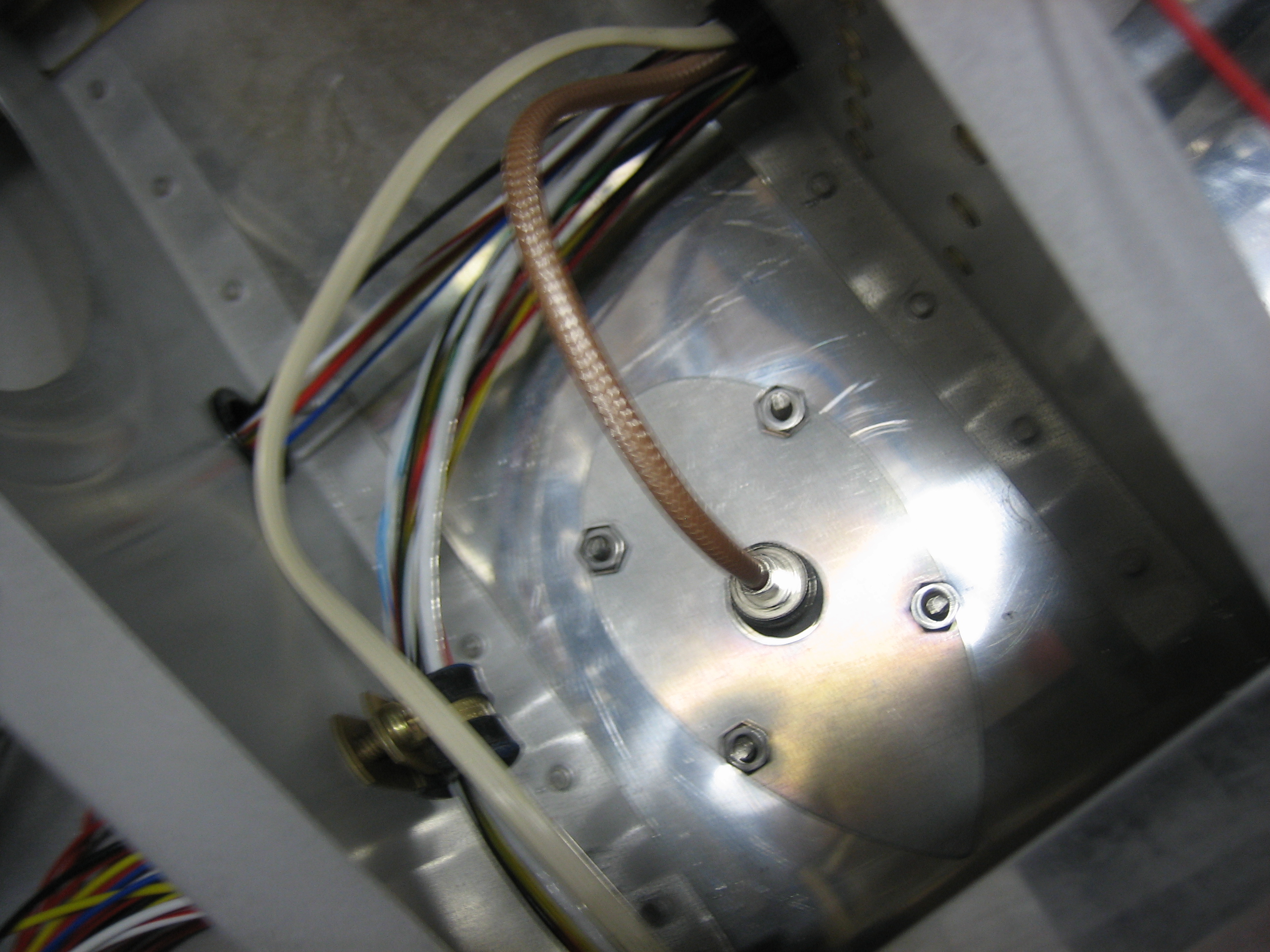
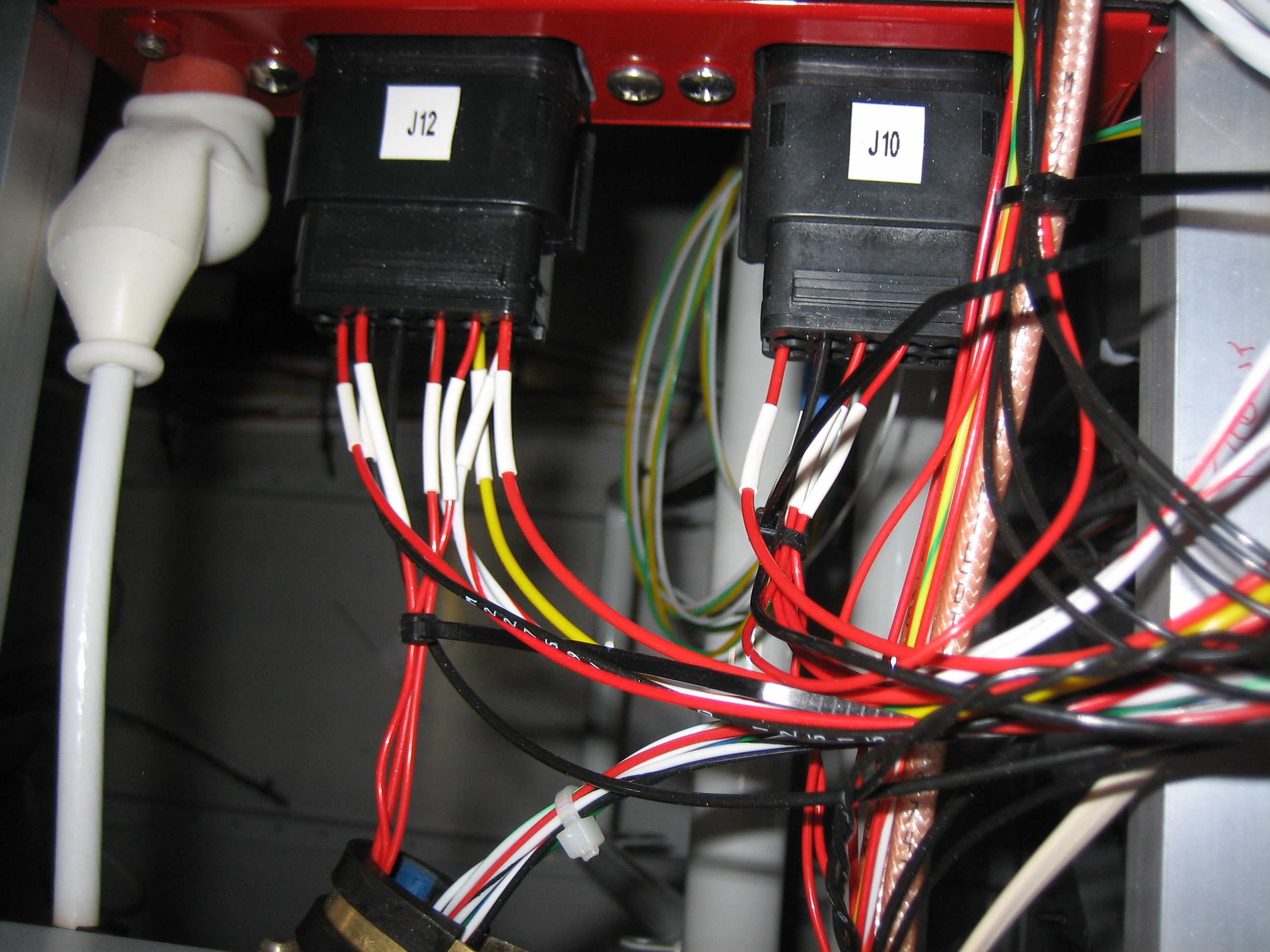
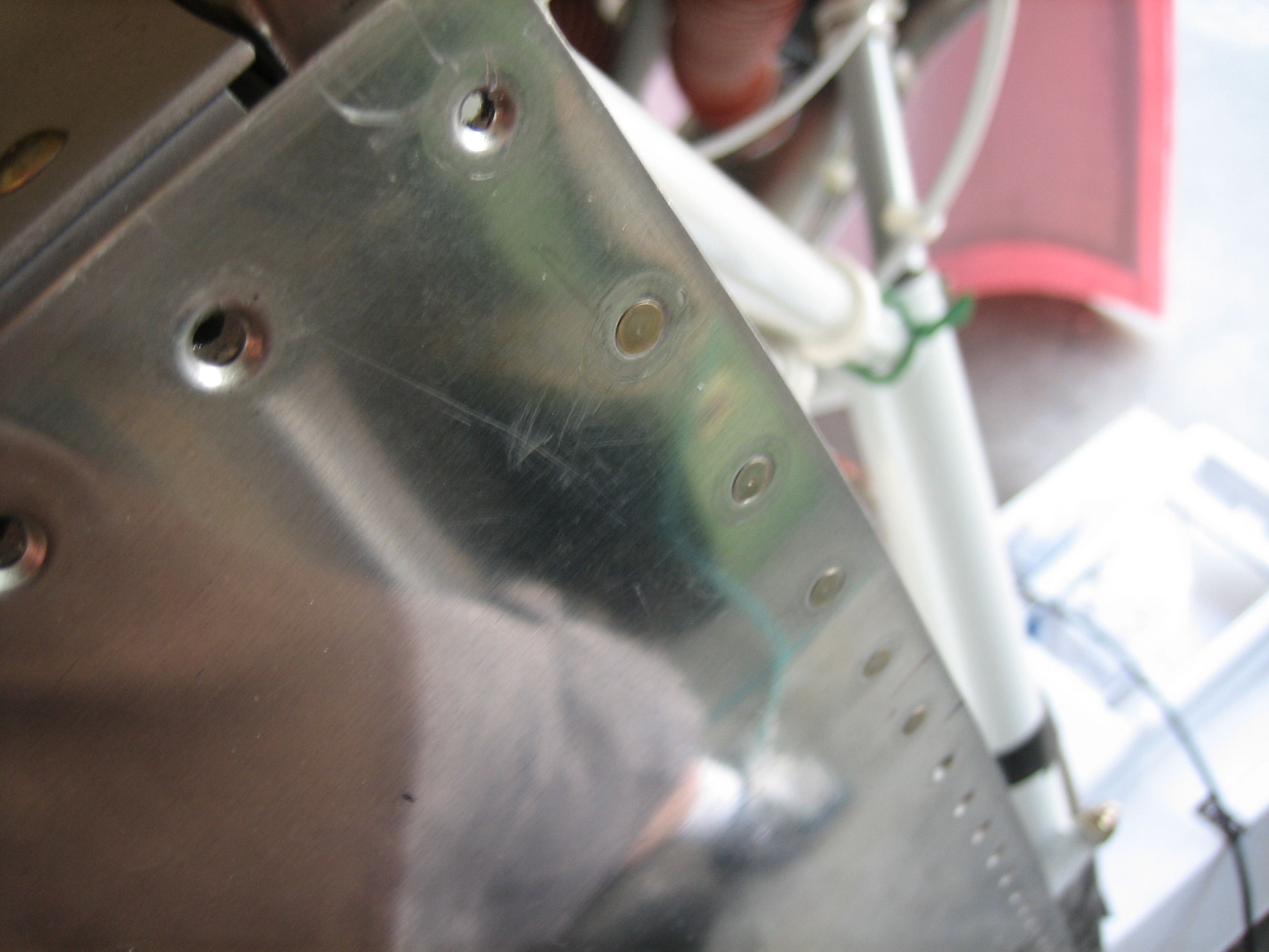
The lines cut through a hole in the post and then join the network cable in the run up to the ADAHRS.

The pitot and AOA lines connect directly to the ADAHRS.  The static line connects to a tee to join the aft tailcone run to the forward fuselage run.

Received AveoMaxx Taxi/Landing Light

I received one of two AveoMaxx taxi landing lights from Aircraft Spruce today.  These lights are very compact and very bright, but all LEDs for low power consumption, heat, etc.  They come in a nice anodized aluminum enclosure that will be mounted in my wing tips.  Since they will be mounted a lot farther forward than the typical wingtip landing lights, I’m hoping the longitudinal face of the wing tip cutout won’t shade the area in front of the plane from receiving light.  The holes on the top will be used to mount the nav/strobe lights.  There are actually two separate lights in the enclosure.  The center light is the landing light and is comprised of a single massive (nearly 1 square cm) LED that is focused in a fairly tight spot.  Surrounding that is a ring of small LEDs that form the taxi light.  These have a much greater dispersion to more evenly light up the ramp.  I came out at night and tried these, and the light output is very impressive.  Since I’m installing two, I’m hoping that will be plenty of light for night ops.

Worked on Cowl and Mounted Com Antenna

I mixed up some epoxy and microlight filler along with some white tint and applied it to the inside of the bottom cowl.  It started stiffening up before I could finish, but I got about half of it down.  This fills in the pattern left by the honeycomb core to provide a smooth finish and fill in any pinholes.  I’ll seal this with some neat epoxy tinted white to provide an easy to clean surface.

I decided to go ahead and mount the com antenna.  My wife gave me a hand with the nuts since you can’t reach both sides at the same time.

I then installed a BNC connector on the coax and installed it on the antenna.

I also fabricated a doubler for the transponder antenna.  I’ll need a little help riveting this on.

Finally, I fabricated the transponder antenna cable.  It has a BNC connector on one end and a TNC connector on the other.

Finally, I vacuumed out this bay and reinstalled the shelf in preparation for riveting it in place.

Finished Wiring Exterior Lights

With the final trimming of the cowl complete, I pulled the forward top skin off so that I could do some further wiring.  All of the exterior light wires have been coiled up on the cabin floor for the last couple of weeks.  With access to the VP-X again, I finished running all the wiring runs.  I’m probably done with 80% of the load wiring at this point.  I mostly just have the avionics left to do.

I also ran the static tubing up behind the panel so that it can be plumbed to the alt-static switch.

It comes up the firewall with the other wires and then heads over to the left side of the plane and then aft to the instrument panel.

Finished Tailcone Wiring

With the ELT shelf riveted in, I wanted to finish up all of the tailcone wiring.  One of the final items on the list is the cabin light wiring.  I ran three 22awg wires from the front up through the top of the baggage bulkhead.  This will be inside the cabin frame support and will connect to a small LED spotlight that will have both white and green lights in it (hence the two red wires and one black ground wire).

I then secured all of the wires from the left conduit with an adel clamp on the ELT shelf rib and some zip ties.

I also ran an additional RG-400 cable through the right conduit for the Garmin GTN-635 GPS antenna.  I had originally planned to mount both GPS antennas (the Garmin and the Dynon) under the cowling, but the Garmin install manual stipulates that GPS antennas not be installed closer than 9″ from each other and require a 7.5″ minimum radius ground plane under the antenna.  Though under the cowling would likely work just fine most of the time (and I’m still going to mount the Dynon antenna there), I want the highest possible antenna performance for my primary IFR navigator.

I finished all of the wiring runs up to the area behind the subpanel, though the cabin light ground is the only wire I could actually hook up to anything.

Worked on Cowl Attachment and Dynon GPS Antenna Mount

Now that I know where the side hinges will rivet to the firewall, I riveted the sides of the firewall flange above that point.

Then riveted the hinges on below that.  The bottom seven rivets can’t be reached with the squeezer, so I’m going to have to shoot and buck them somehow.

I’ve been planning on mounting the Dynon GPS antenna under the cowl.  Most builders fabricate a little shelf that runs between the engine mount and the firewall, but that would get in the way when changing the oil.  Since I only have one antenna to mount, I decided to fabricate a small mount that will attach directly to the engine mount.  I placed the straightedge between the top of the firewall and the spinner to see how high I can go.  The actual cowl in convex through here and will actually provide more clearance than this.

The mount is just a short piece of Z channel that I trimmed to fit the antenna.  I’ll drill a couple of holes in the bottom flange and attach it to the engine mount with a couple of adel clamps.

Ordered Avionics Stack

I ordered my avionics stack today.  I’m going with a PS Engineering PMA8000BT audio panel and Garmin GTN 635.  I went back and forth about both units a bit.  I was originally going to install the PMA5000EX audio panel, but ended up deciding the Bluetooth functionality would be worth it for making phone calls and listening to music.  I was also originally planning on installing the GTN 650, but ultimately didn’t think I would use the VOR/Loc/Glideslope functionality much.  Switching to the 635 not only saved me about $1,000, but the unit is 0.8 lbs lighter and I probably saved another several pounds of antennas and wiring (not to mention hours of time that I would have spent hooking up the additional antennas).