I traced the cowl inlets on some card stock and transferred it to some hardboard. I’ll use these to define the position of the plenum.
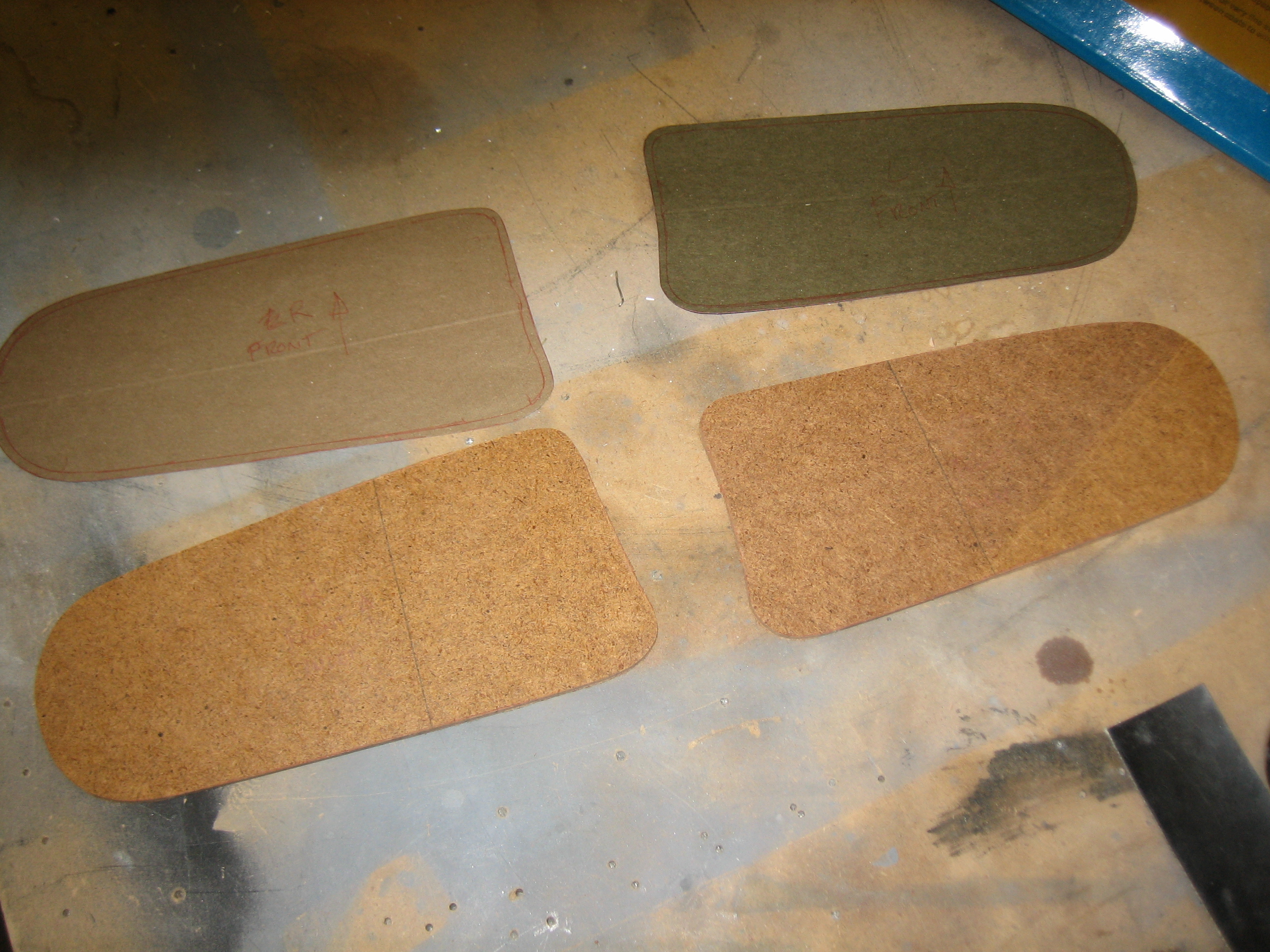

I traced the cowl inlets on some card stock and transferred it to some hardboard. I’ll use these to define the position of the plenum.
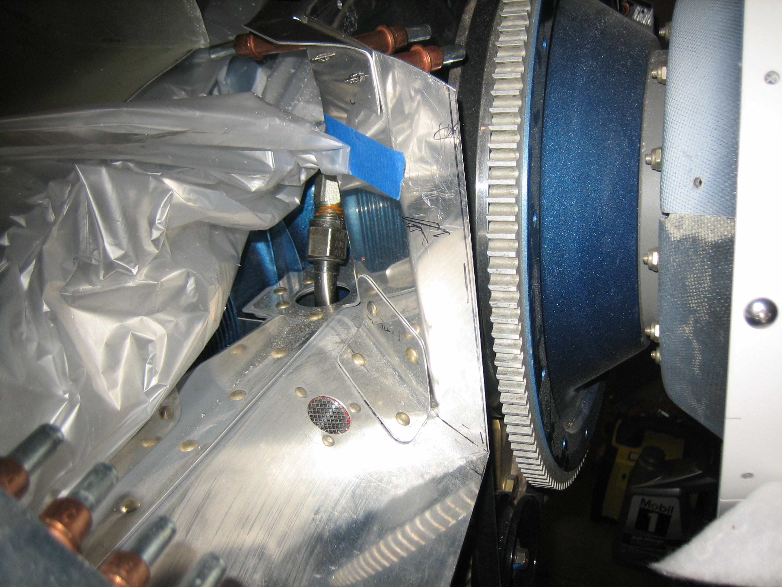
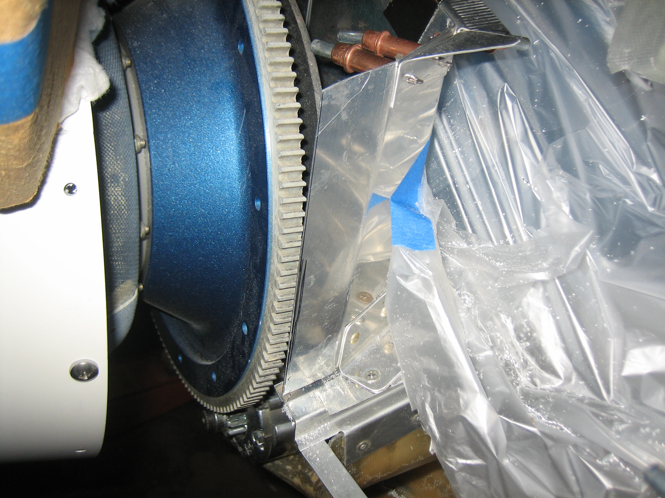
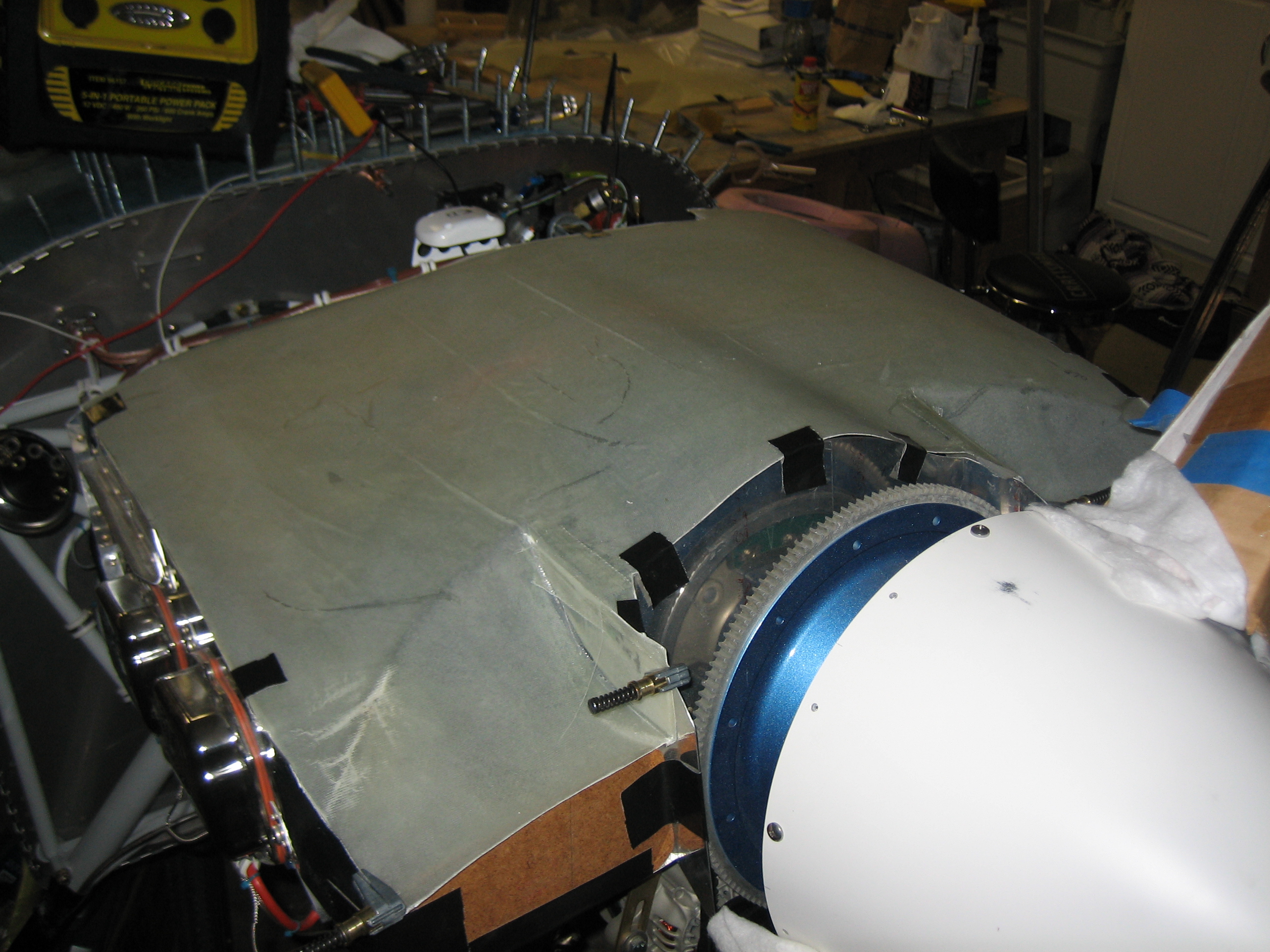
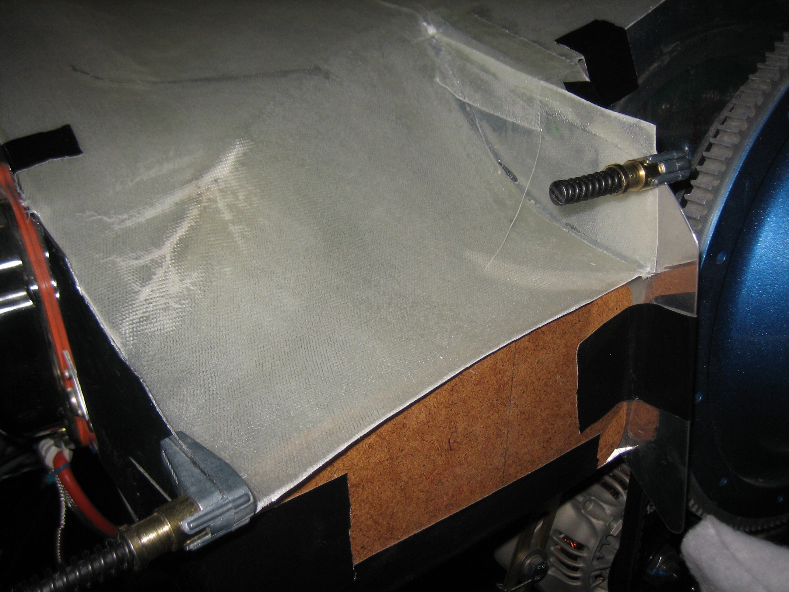
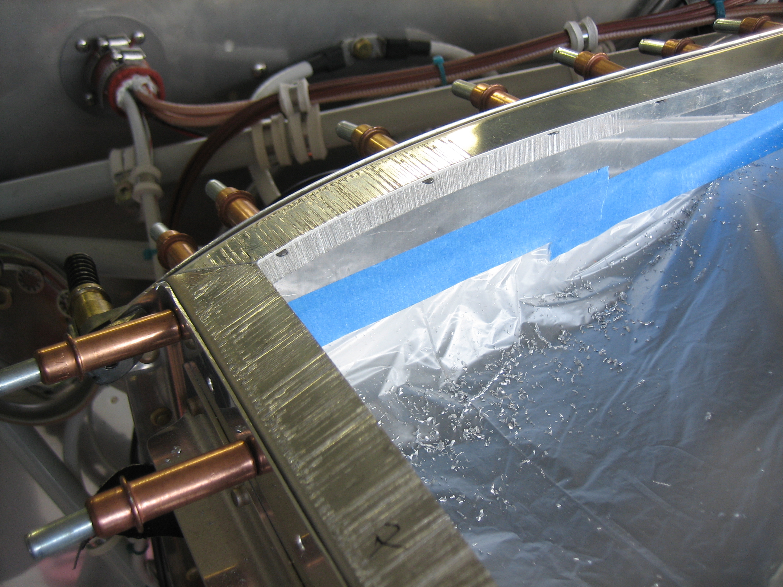
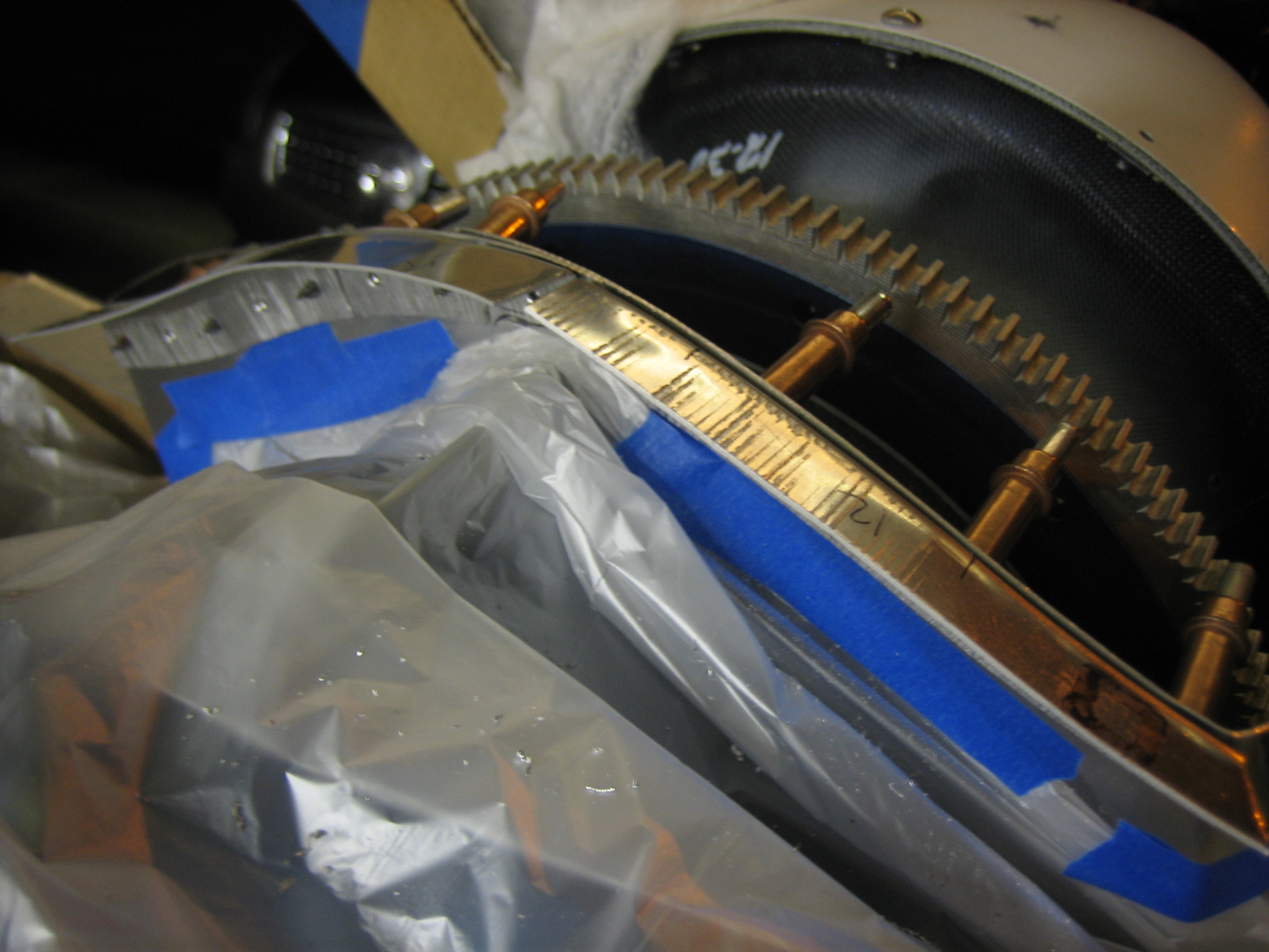
With the templates I made yesterday taped in place, I installed the plenum and taped it down.
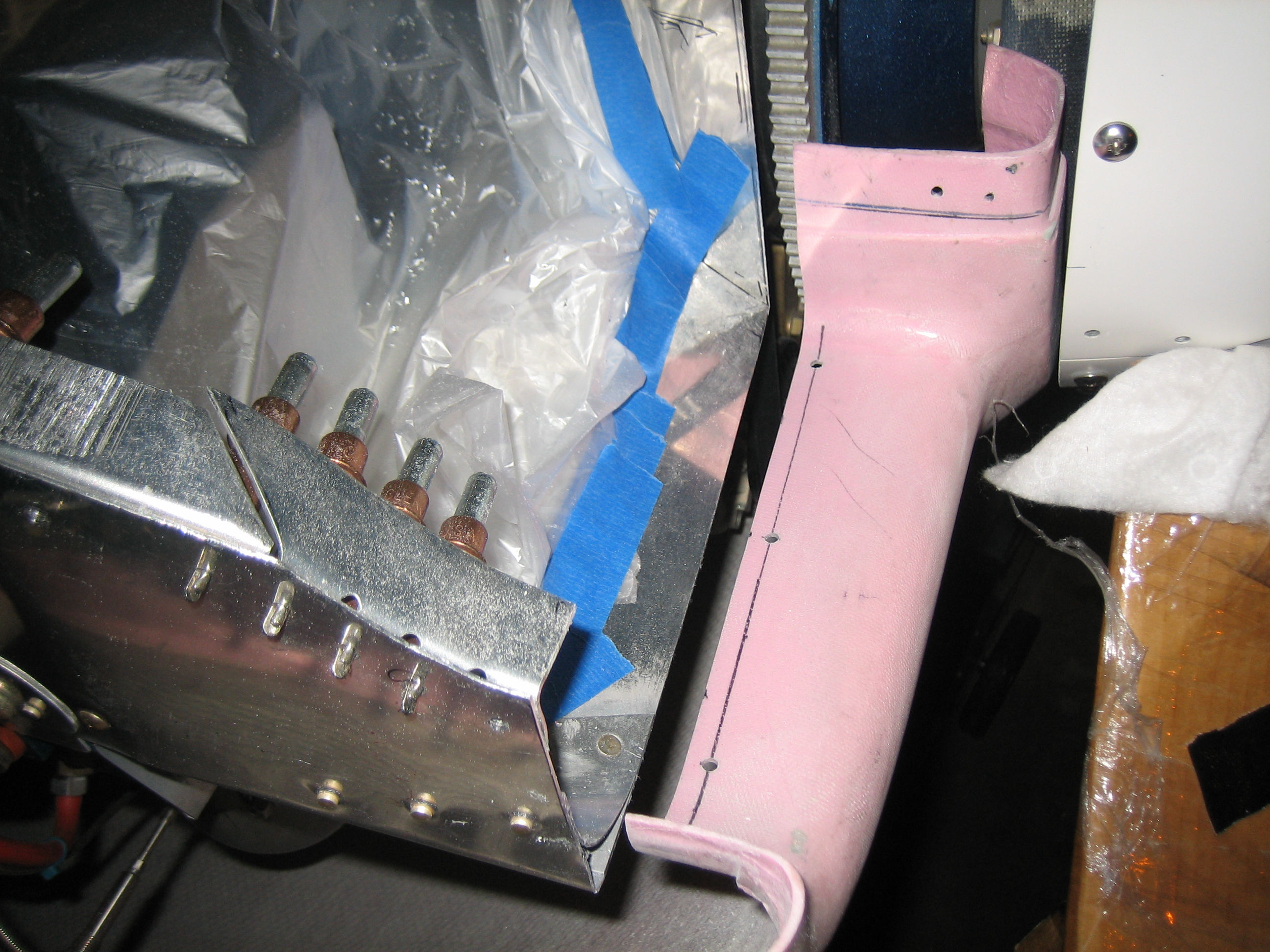
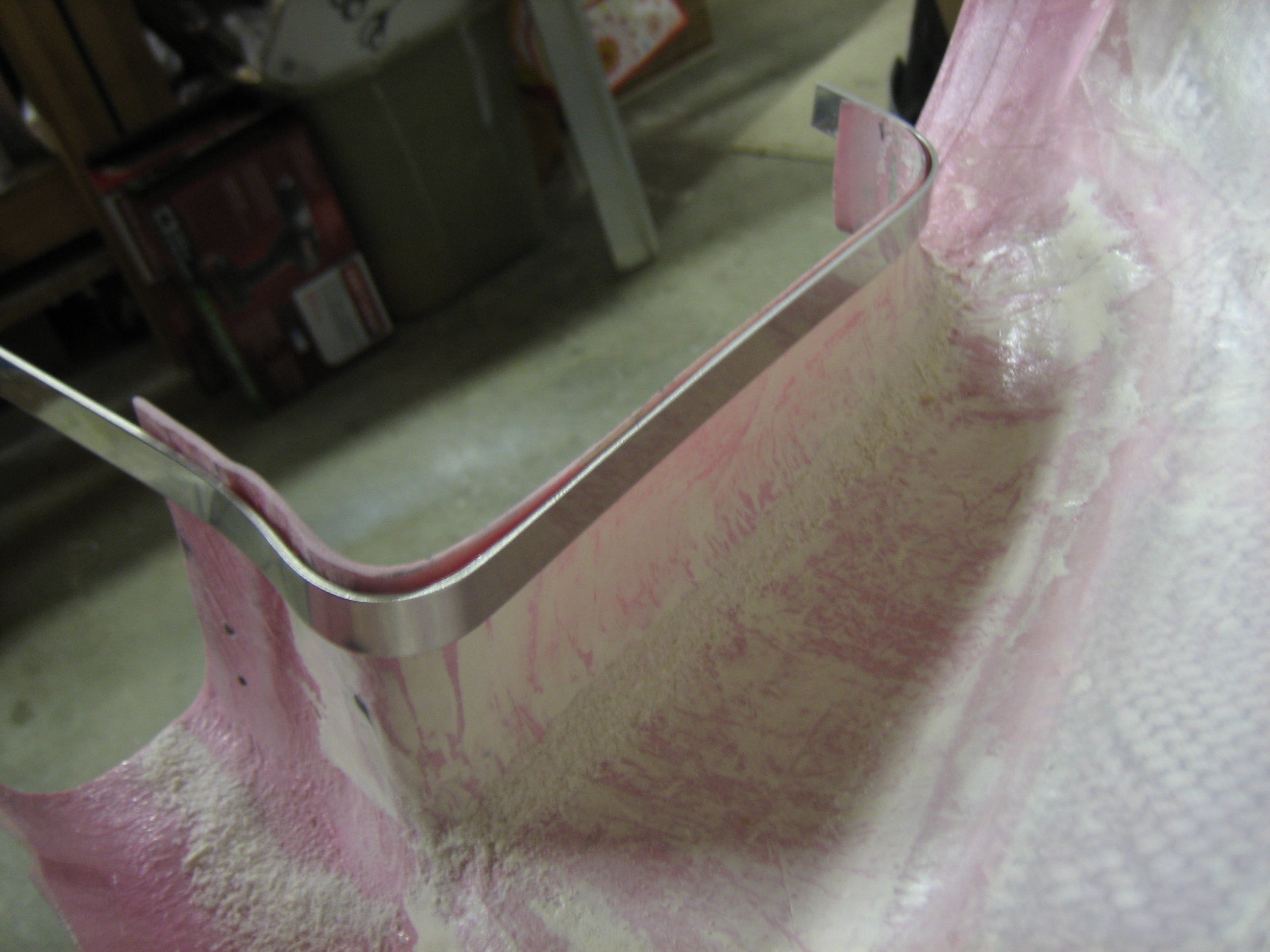
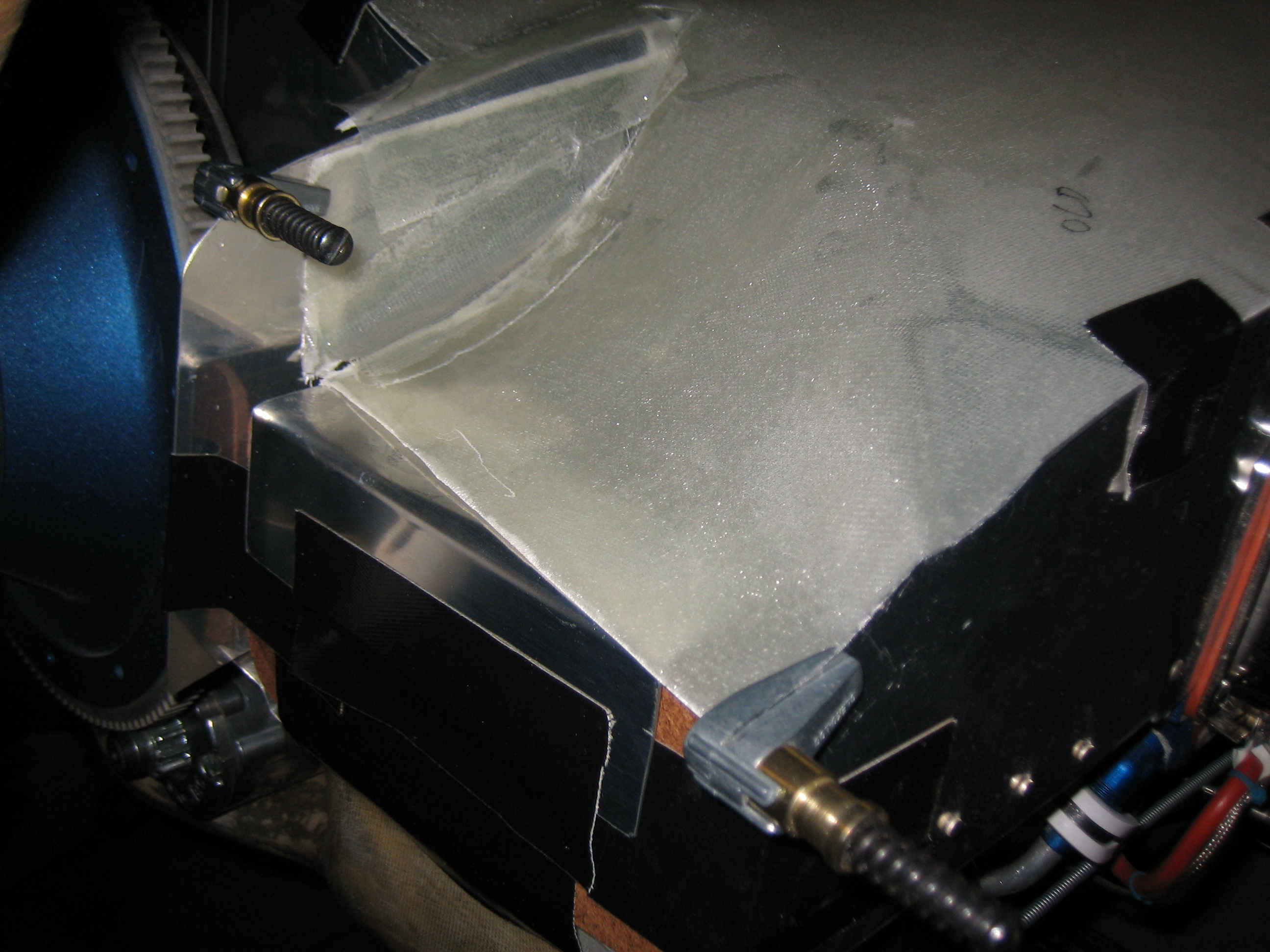
I trimmed the inner edges of the ramps and added some glass to get the plenum to fit tight against the forward baffles. Here’s the right inlet.
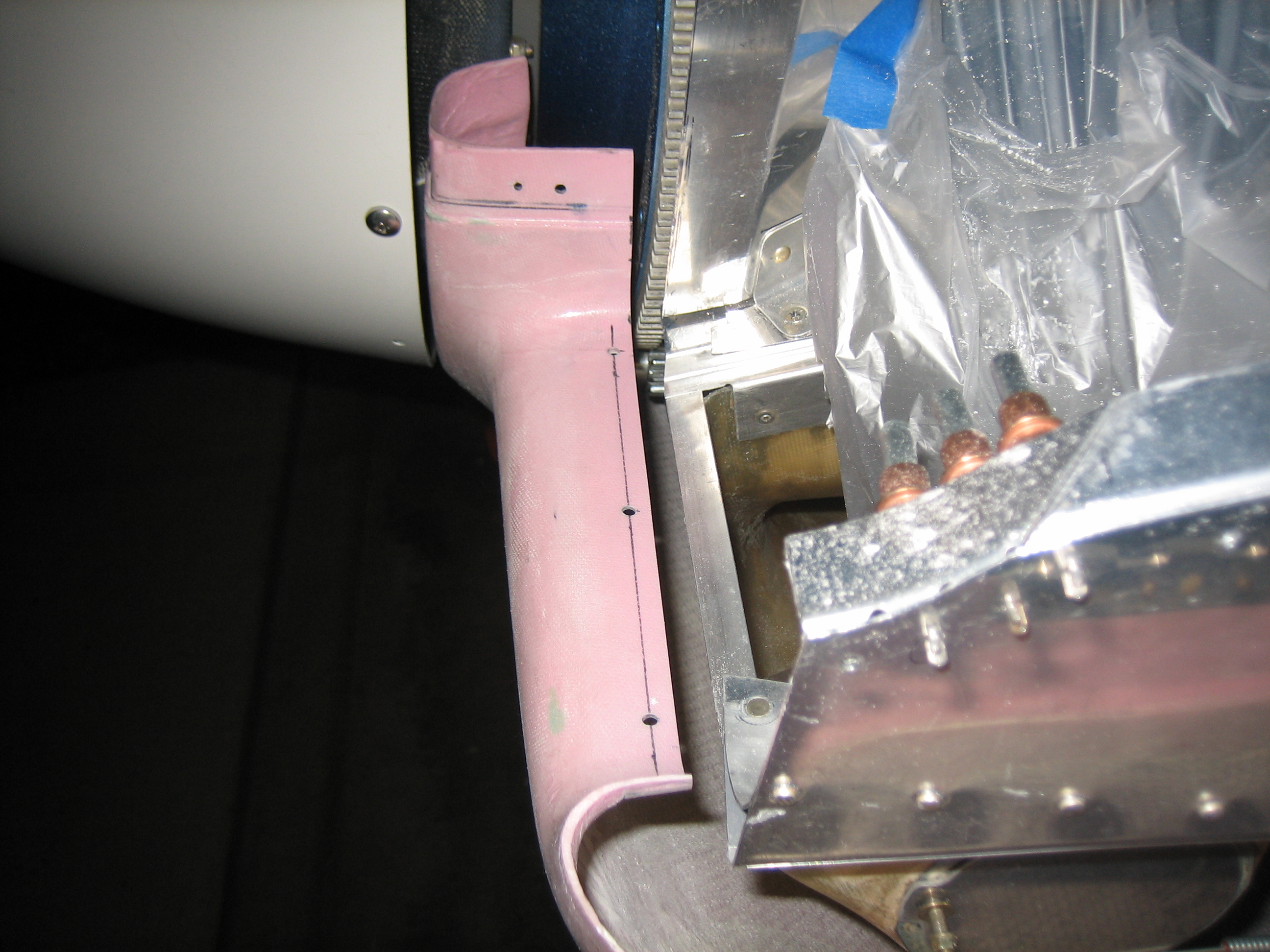
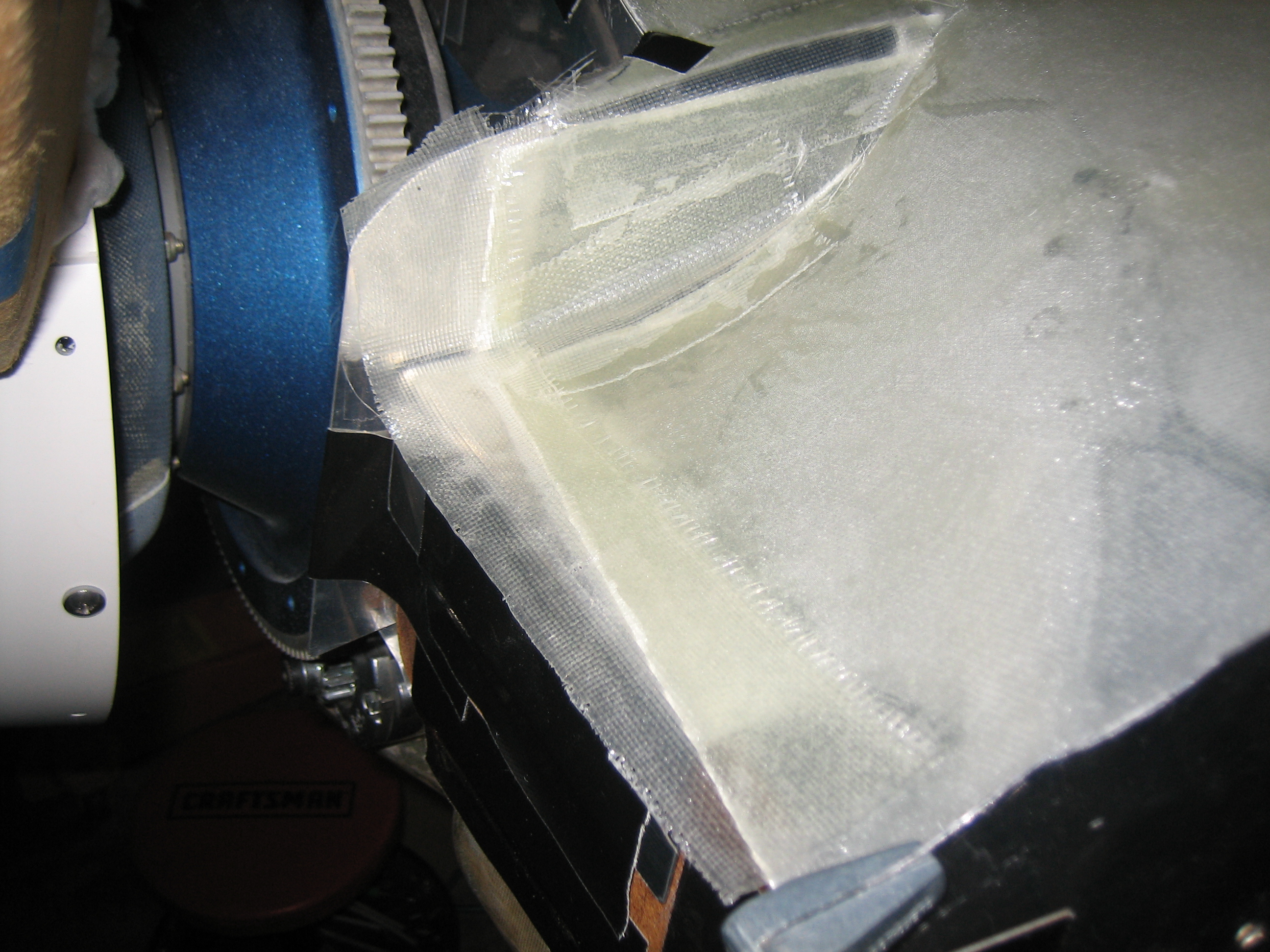
Here’s the left inlet. After curing, these fit really well, but I’ll need to extend the glass on this side about an inch on the inner edge.
I added more glass to the front edge to bring it out past the face of the template.
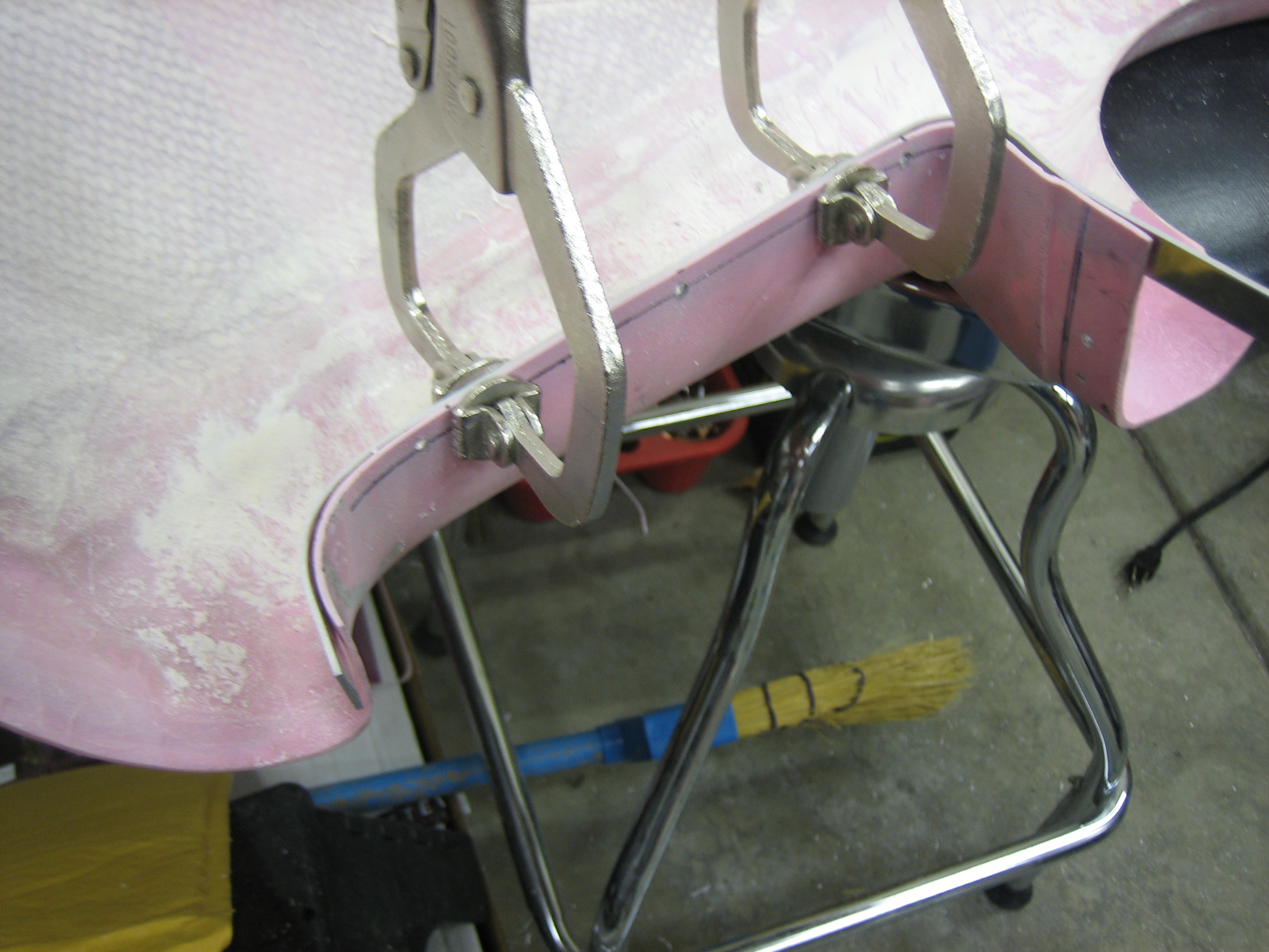
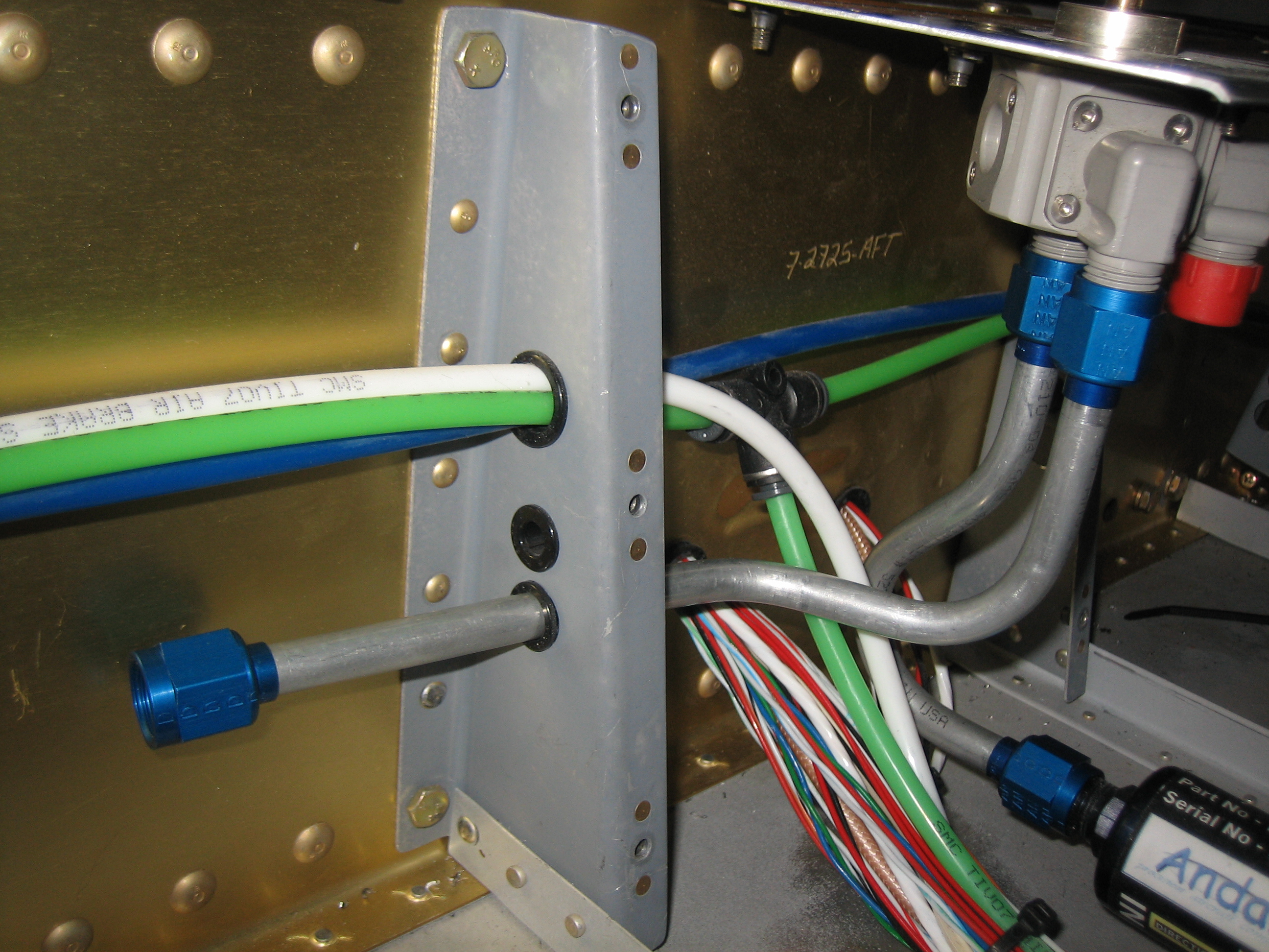
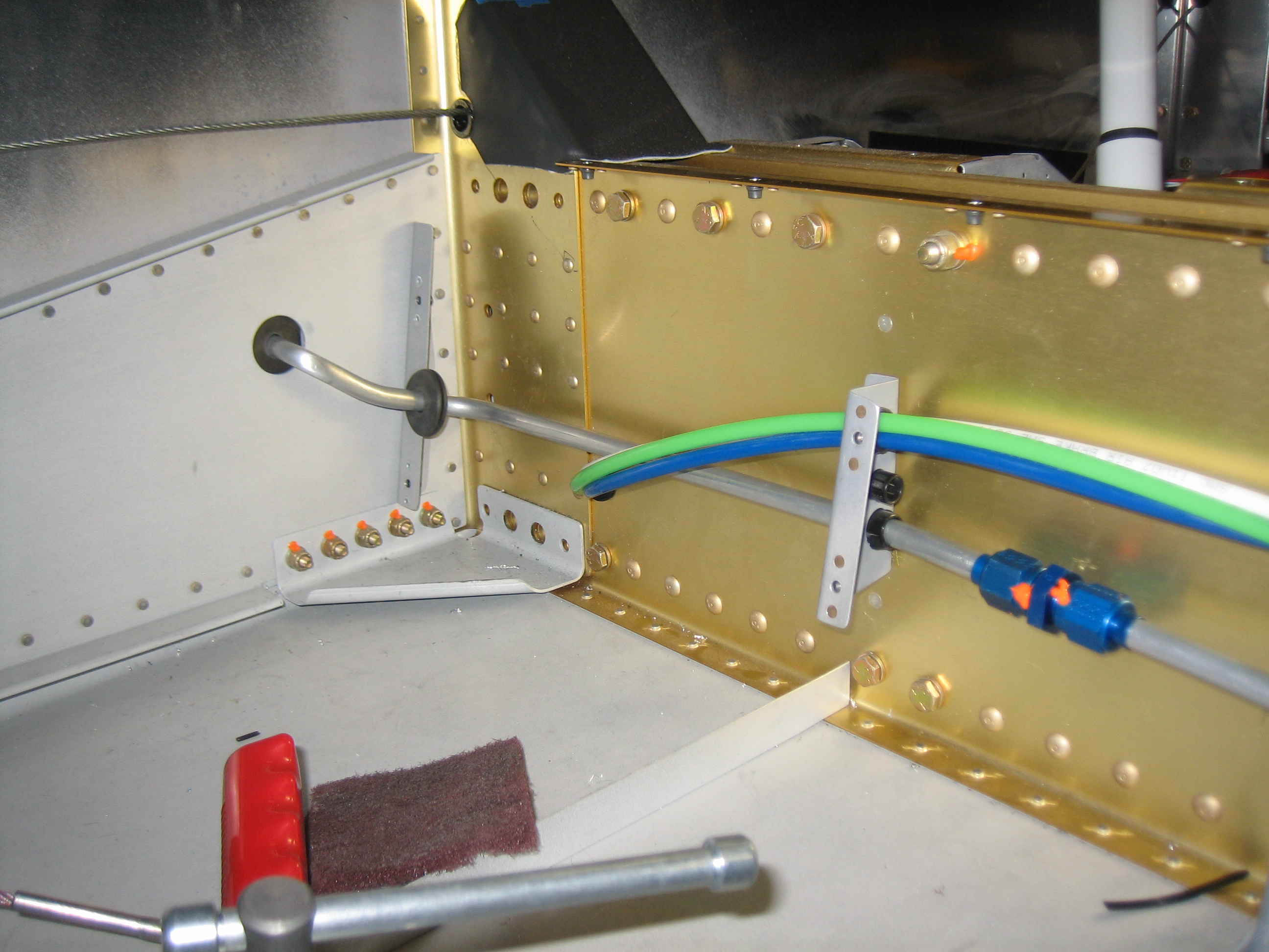
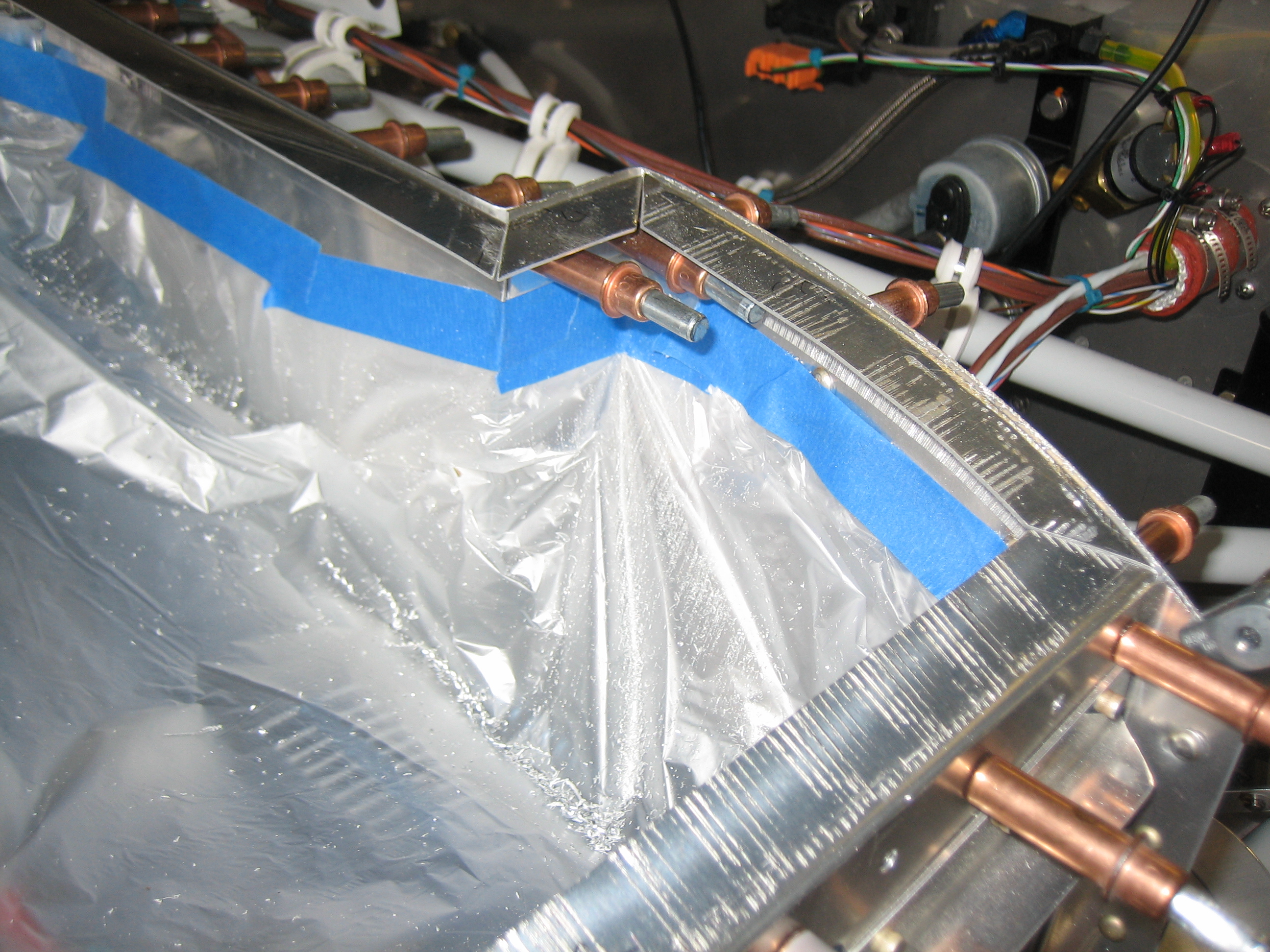
While the fiberglass was curing, I got started bending the fuel lines that go from the fuel selector out to the wings. Each side will be done in three pieces, a piece from the fuel selector to between the support brackets (as seen here), a second piece from between the support brackets to just outside the fuselage, and a third piece from there up to the fuel outlet on the tank. Each section will be joined with an AN815-6D union. This is necessary because it’s essentially impossible to maneuver longer pieces through the holes in the support brackets.
I fabricated the other short fuel line up to the fuel selector as a mirror image of the right side.
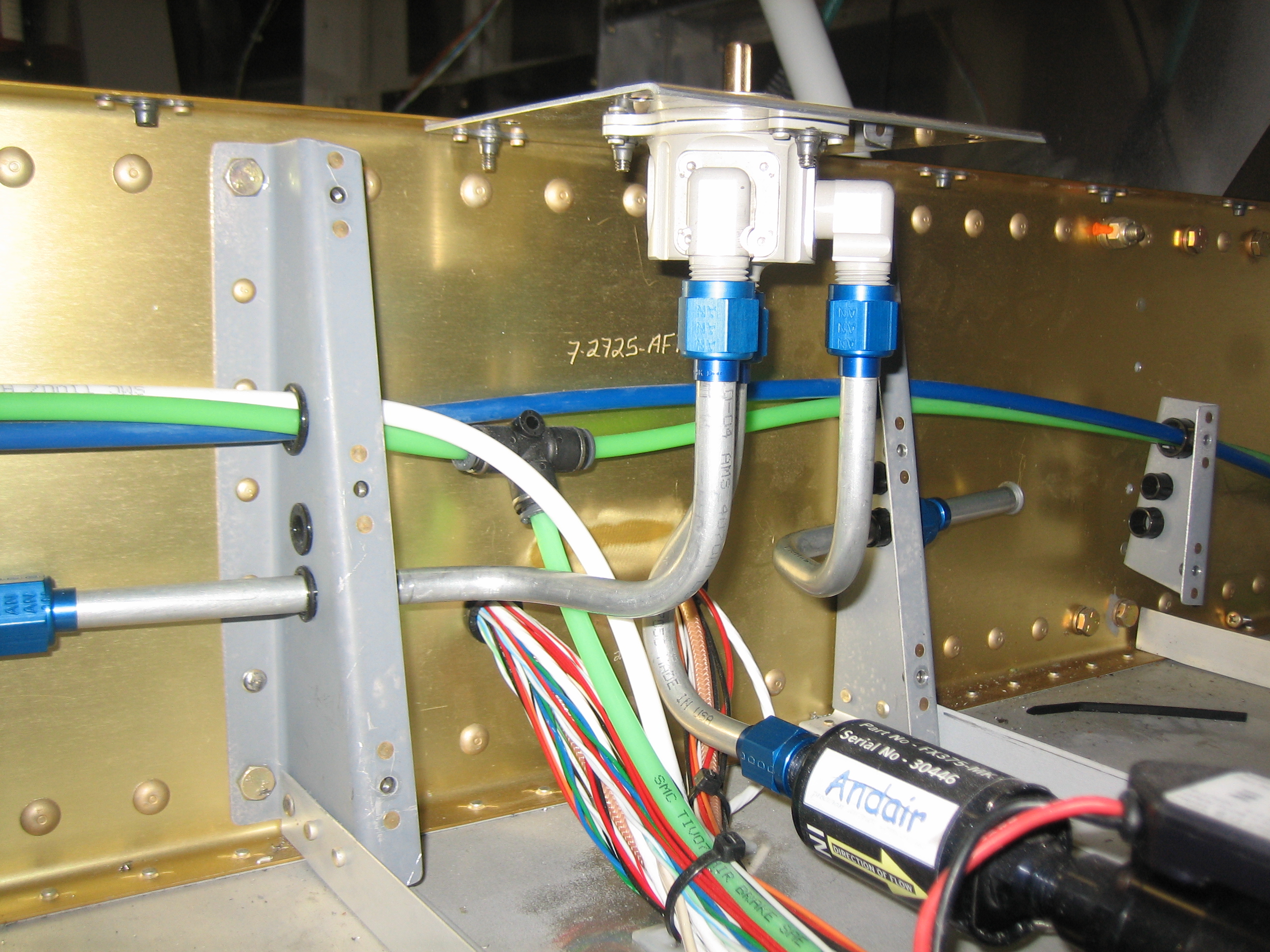
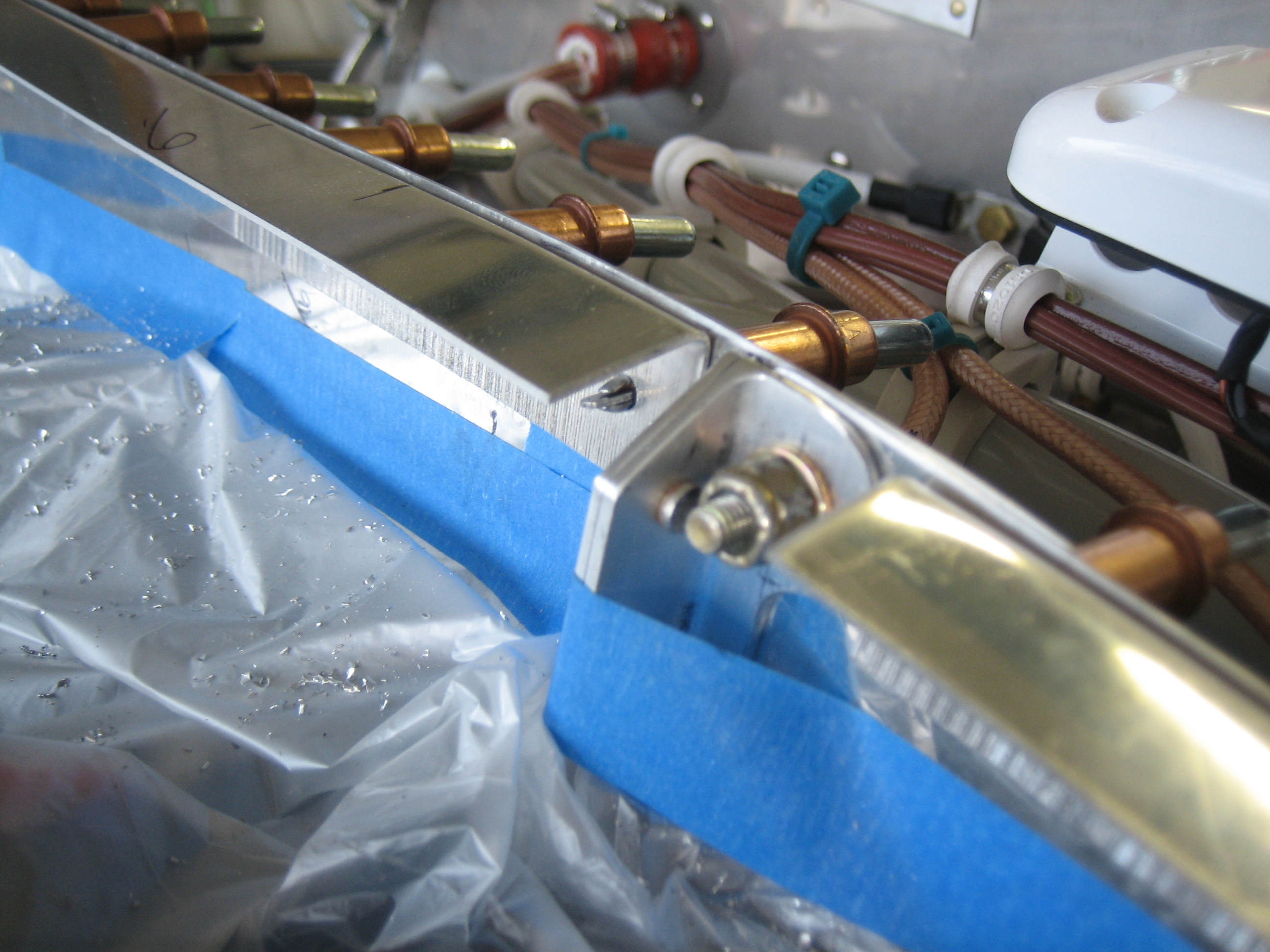
I then fabricated the line up to the union that passes through the side of the fuselage. I don’t have the unions yet, but they should show up tomorrow.
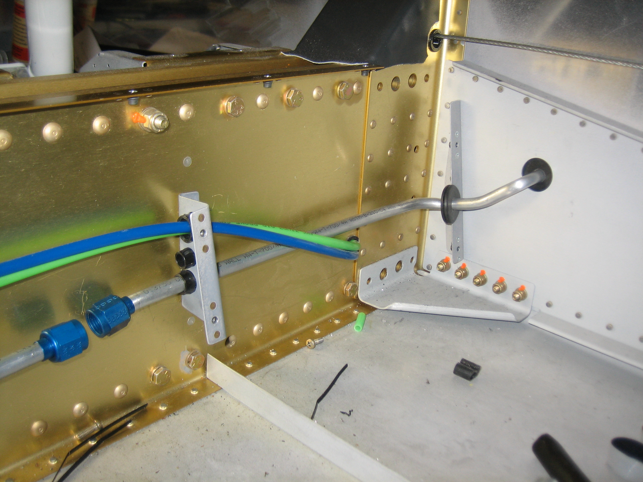
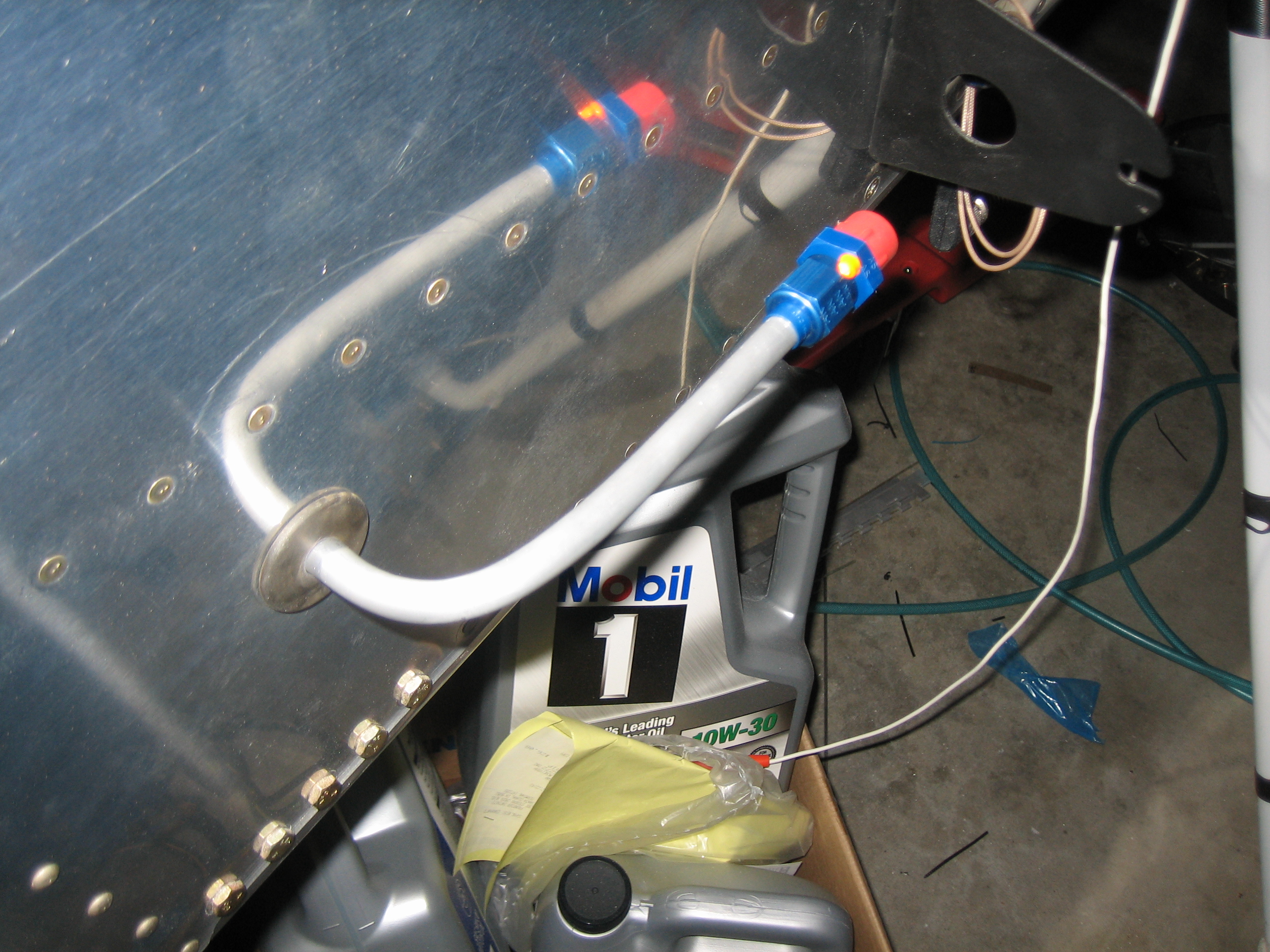
On the outside of the fuselage, the line turns forward. There will be another union here and a short line from the fitting on the fuel tank. It’s unfortunate to have this many fittings, but the only other reasonable option is a flex line from each tank all the way to the fuel selector. That would be heavier and would require periodic replacement. As long as I don’t have any leaks, these are a much better solution and will last the life of the plane.
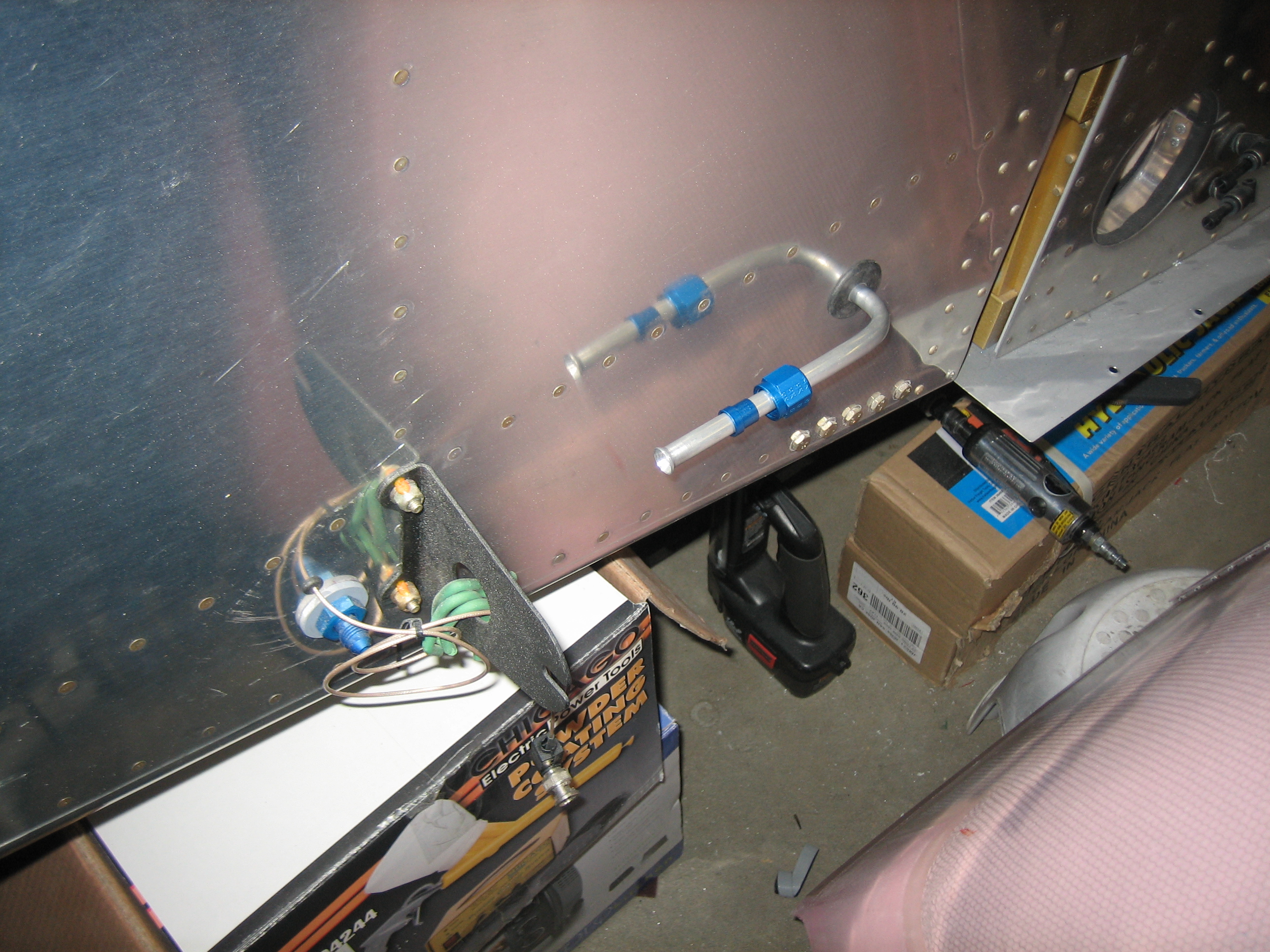
I finished fabricating the last of the interior fuel lines tonight. This one took less time than any of them and turned out perfect.
Just like the other side, the line turns forward and aims toward the hole in the tank support bracket.
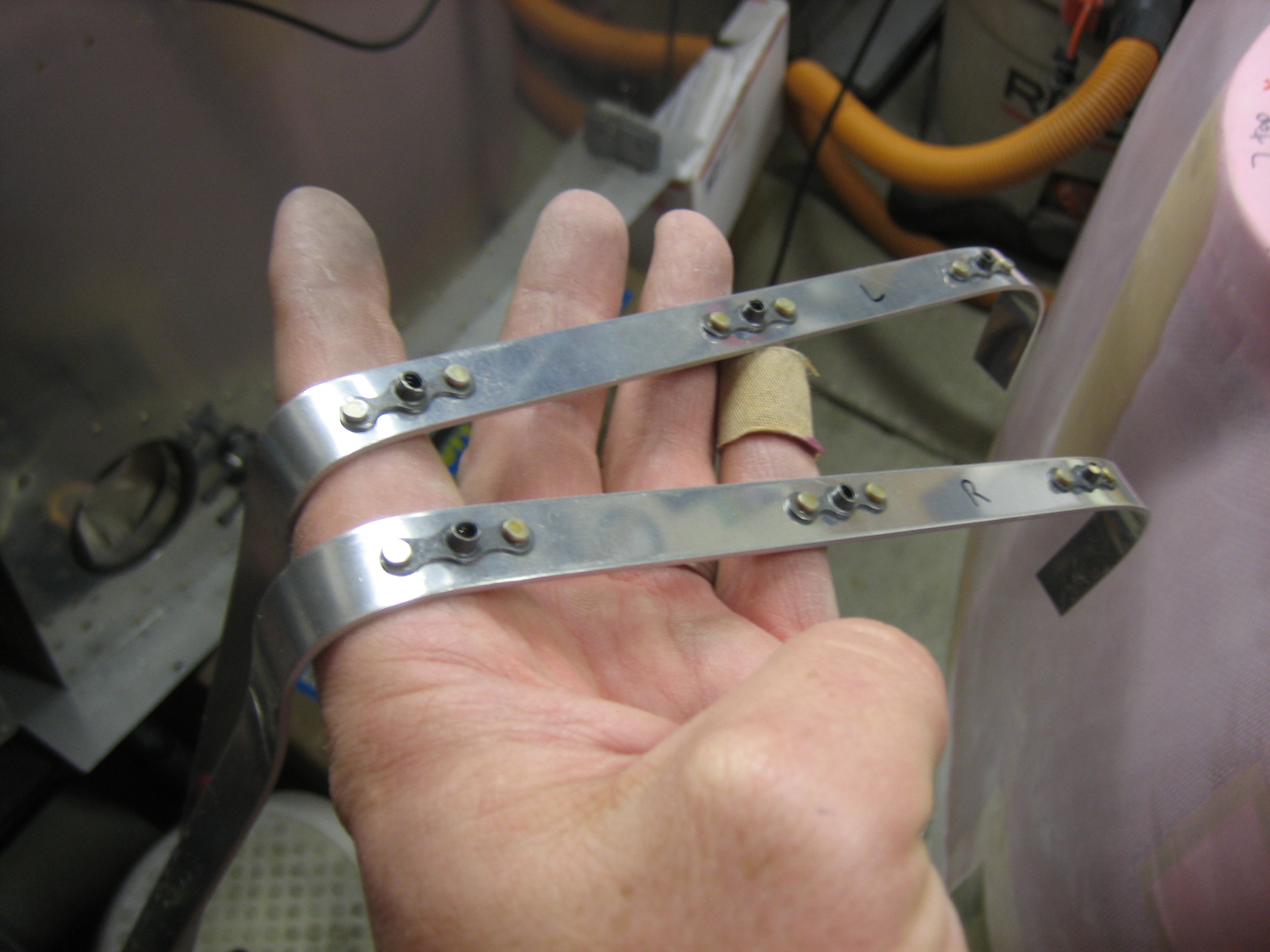
I started fabricating the plenum mounting angles tonight. These are a little tricky because they’re not 90º and they’re all curved. Here are a couple of the ones around the oil cooler air inlet.
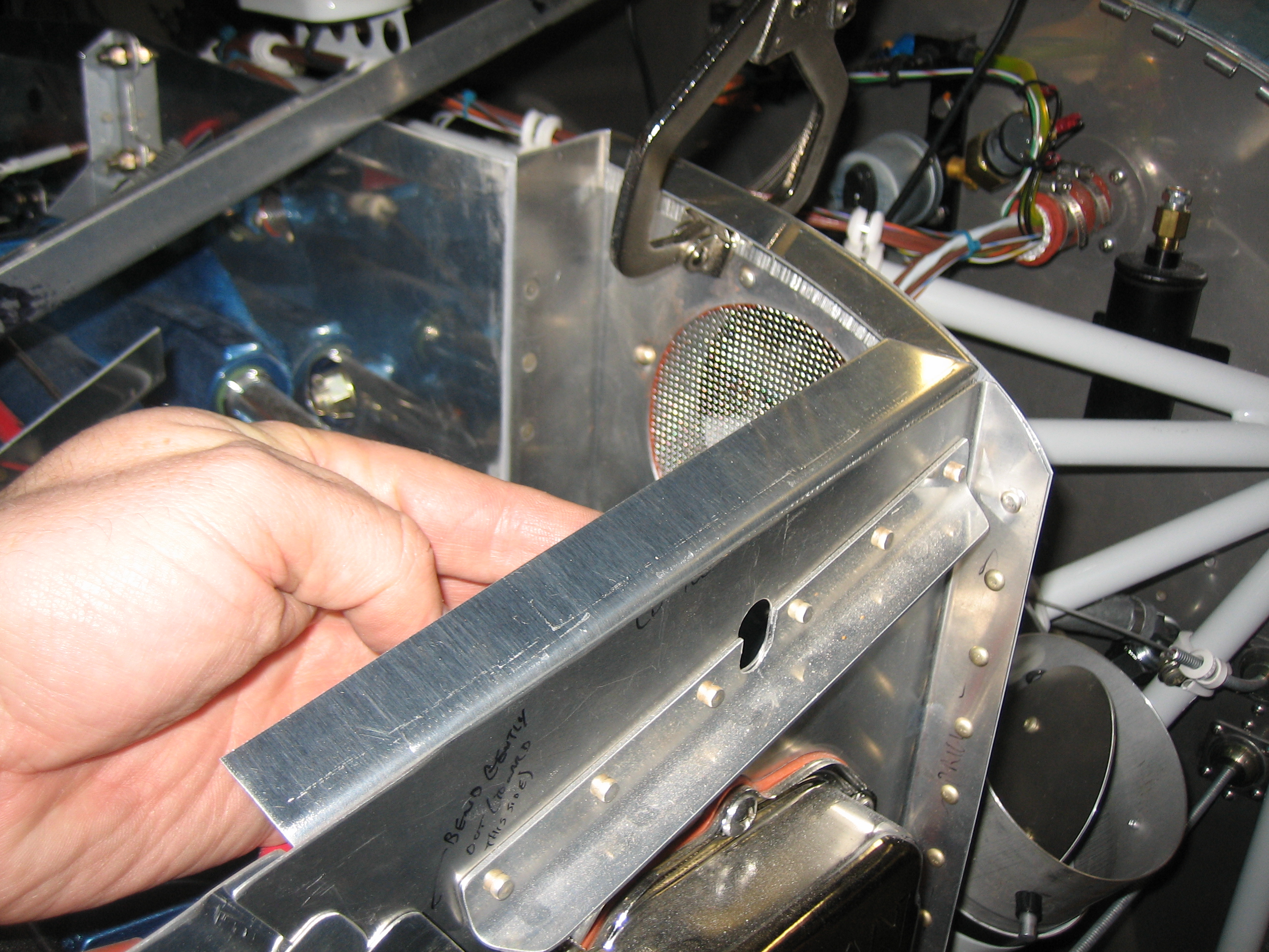
Here’s the angle along the aft edge on the right side. There’s a fairly severe curvature near the end.
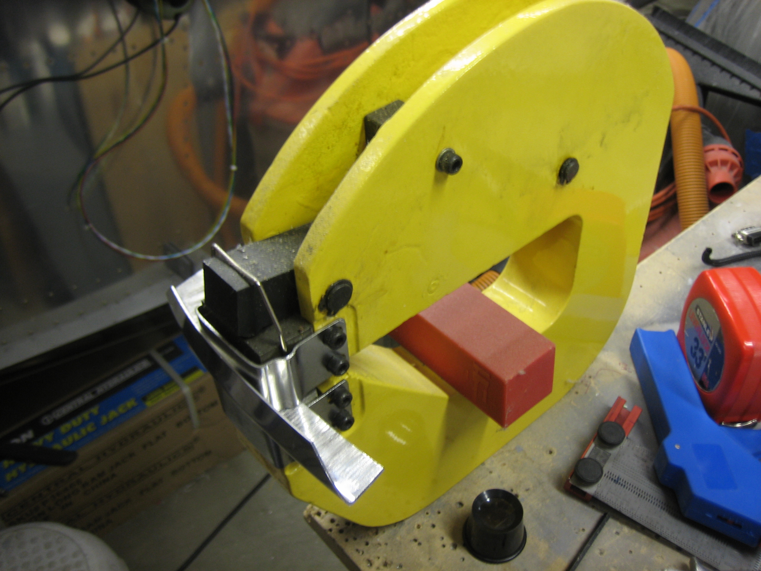
I’m using my shrinker/stretcher to curve the angles.
This is angle above the oil cooler air inlet. The shrinker/stretcher leaves some fairly deep marks in the aluminum, but these will sand out.

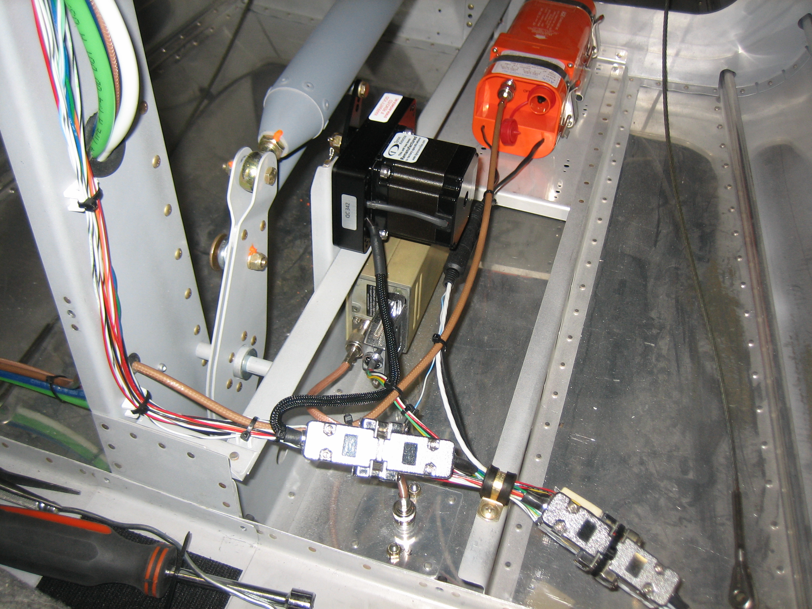
Way back in September, I mentioned that since upgrading to SkyView 4.0, the SkyView system wasn’t finding my pitch servo. After double checking the wiring at the request of Dynon, I couldn’t find any problems. Dynon ended up sending me a new servo which completely fixed the problem.
I then spent a couple more hours working on the plenum mounting angles. I have them pretty much ready to drill to the baffles. I’m sure I’ll have to tweak the angles a bit to get the plenum to sit flat on them.
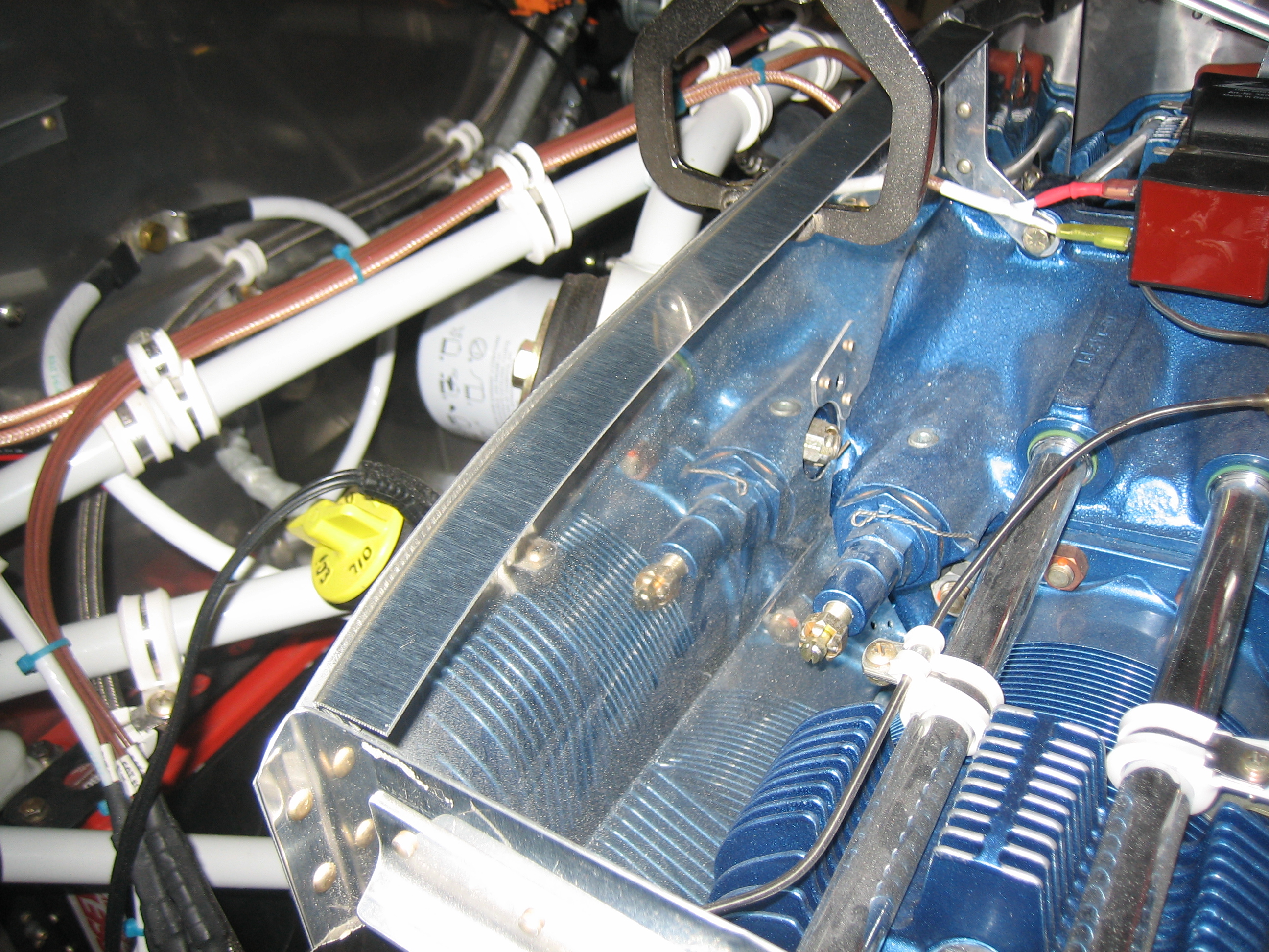
I started drilling the plenum mounting angles tonight. I made it around halfway around the baffles before getting frustrated with the ones along the front of the engine. These have the most curvature of any of the baffles and I kept splitting the metal with the stretcher. I’ll probably end up having to section those angles to get them to curve that much. Here’s the angles around the oil cooler bump out.
There will be a small gap here where the left and right sides of the aft wall join. The plenum will span this and the gap should be tiny if not nonexistent.
Here’s the aft right side of the engine. All of the corners are mitered, and I’ll install a nutplate that spans the gap in the corner to further tie these pieces together.
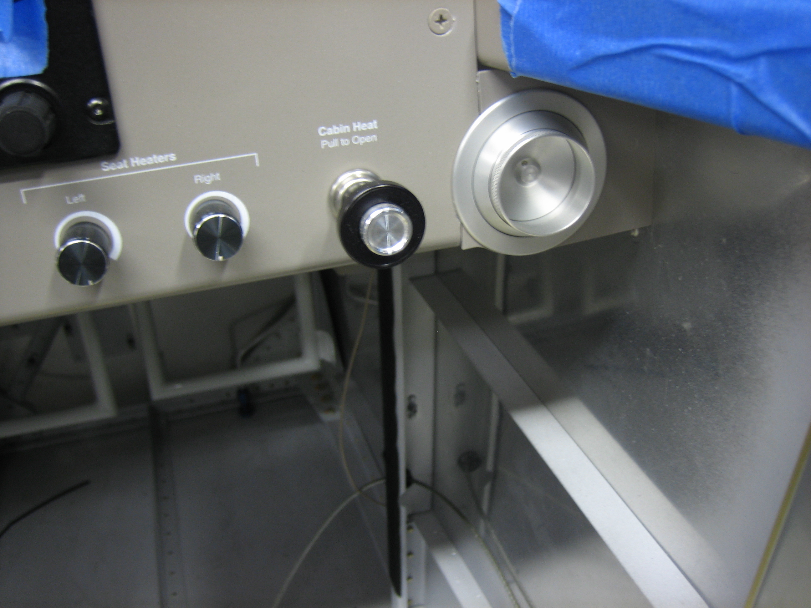
For some reason, I decided to install the air vents tonight. These weren’t too bad, but there’s not a lot of room back there to tighten the mounting nut.
I got the forward plenum mounting angles drilled to the baffles. These were a pain in the ass to curve this much and I ended up having to cut a couple of notches in the left one to follow the curve acceptably. I still have four more very small angles to fabricate and drill before I can move on to finishing the plenum.
I trimmed back the vertical walls on the inner ends of the cowl inlets so that they line up with the front edge of the ramps. Here’s the right side.