Painted Instrument Panel

After sanding the instrument panel with 400 grit sandpaper to smooth out a few rough spots, I shot it with the same paint that matches my leather.  I *think* I’m going to have to sand this a bit and shoot another top coat, but we’ll see tomorrow.  You can see in the lower right of the picture that I also painted all of the screws that will be visible on the panel.

Attached Engine Control Bracket

I got back the engine control bracket from the welder.  I’m using the bracket from Experimental Air, but I took about 1/2″ off the top to give myself a little more knee room.  This required having a welder attach a new top plate so that it could be screwed to the bottom of the panel.

I used three screws to attach the bracket.  The one in the middle required a hole in the bottom flange to allow me to use a straight screwdriver to access this screw.

I installed nutplates on the bottom flange of the instrument panel.  I was a little concerned that the one on the left would interfere with the switches, but there’s over 1/4″ of clearance.

Primed Engine Control Bracket

Our developer conference is over.  It was an exhausting week with sessions and labs all week and eating and drinking until the wee hours each night.  I’m exhausted, but I’d like to try and get the panel installed this weekend.  In order to finish up the paint tomorrow, I needed to get the engine control bracket primed tonight.  I also primed a piece of scrap aluminum flashing that I’m going to paint and use as a test for installing some labels.

Since the headset jack brackets have now been painted, I installed the headset jacks for good.

Finished Painting Instrument Panel

I finally finished painting the instrument panel.  I kept having problems with orange peel in the paint as well as dust and debris since I don’t have a paint booth.  I mostly fixed the orange peel problem by switching from my cheap Harbor Freight spray gun to my nice Fuji HVLP spray gun.  It’s not perfect, but it looks great.  After it cures, I can label it and spray a clear coat over it to protect the labels.  The scrap piece in the upper left is so that I can try different label colors to see which is easiest to read.

Started Labeling Panel

Work has been really busy lately, so I’ve had almost no time to work on the plane.  We’re off tomorrow for the 4th of July, so I decided to take tonight and get started labeling the panel.  I’ve been practicing with the DecalPro system for a little while, but I was really having a hard time getting the white labels to turn out nice.  I called Frank at Pulsar and he gave me a couple of suggestions that solved my issues, and now almost every label turns out perfect on the first try.  Basically, my process is:

  1. Make sure the toner density is set to 5 on my HP laser printer to ensure good foil adhesion and edge definition.
  2. Clean the label and the back side of the white foil with rubbing alcohol.
  3. Thoroughly dry the label with the heat gun on both sides.
  4. Wipe the label and the back side of the foil with the tack cloth.
  5. Laminate the foil to the label using two passes.
  6. Peel off the foil and remove excess using the low-tack masking tape.
  7. Clean the label and mylar transfer foil with rubbing alcohol (rubbing the mylar vigorously to build a static charge).
  8. Laminate the mylar to the label using two passes.
  9. Trim excess mylar.
  10. Run the label back through the laminator one last time without the carrier board.
  11. Put the label in the water until is separates from the water slide paper (be patient here, rushing will only cause the image to break up).
  12. Dry the label.
  13. Trim borders from the label.
  14. Apply adhesive.
  15. Apply to panel.

There are a lot of steps, but it goes pretty fast once you get the hang of it.  I also tend to overlap the process somewhat by getting started on the next label while the previous one is in the water.

Anyway, I actually started with the largest and most complex label, and it came out essentially perfect.

Next up, I labeled all of the switches in the upper left of the panel.  Unfortunately, I didn’t notice that the line over the ignition switches was shifted to the left until I was applying this.  I’ll pull it off and print another one tomorrow.  I still have quite a lot of labels to go, but I’m hopeful that I can wrap this up tomorrow since I’m off work.

Finished Labeling Panel

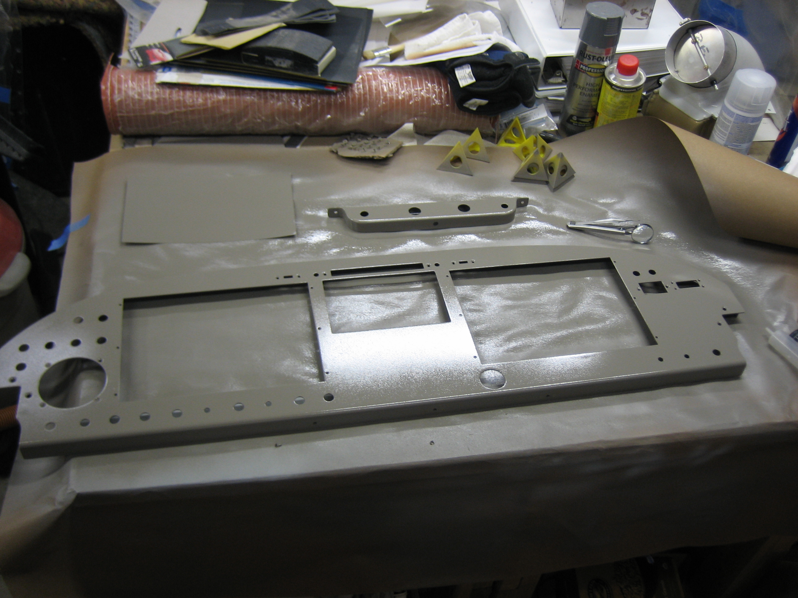
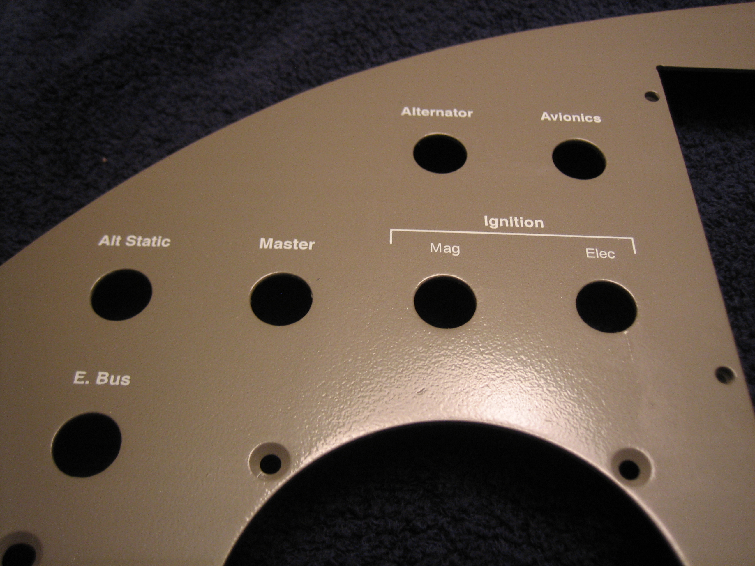
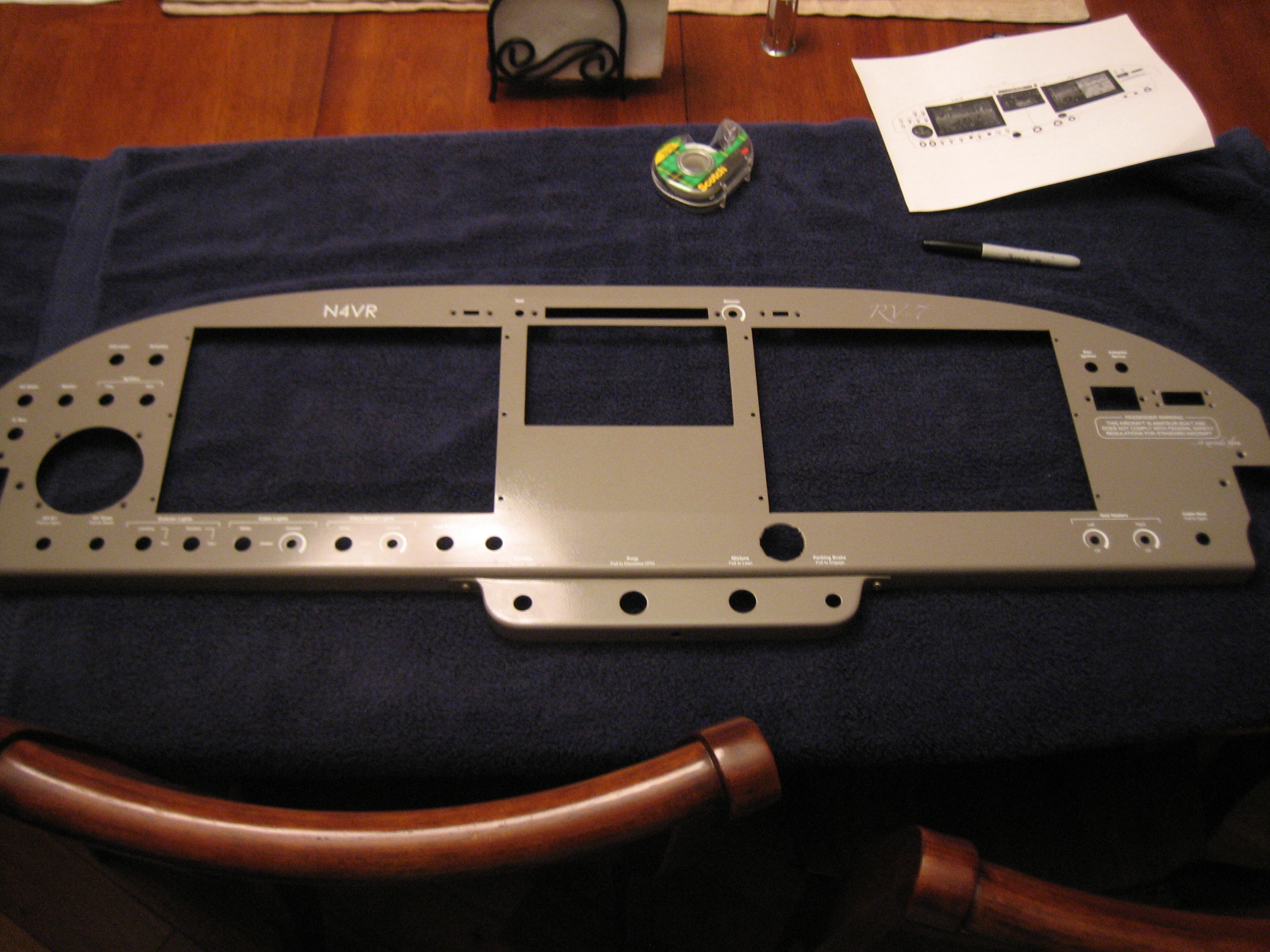
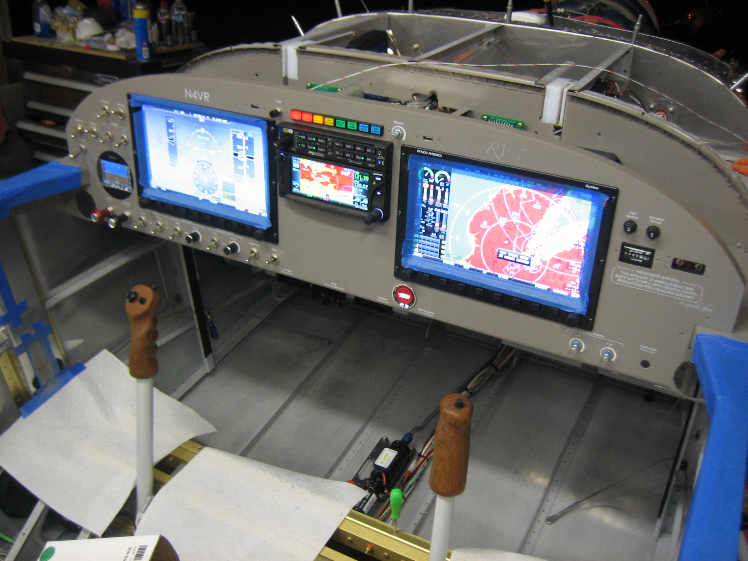
I finished labeling the panel today since we were off work for the 4th and my wife had to work all day.  Here’s an overall shot.

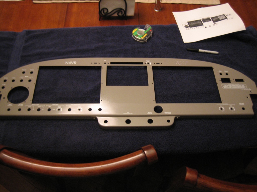
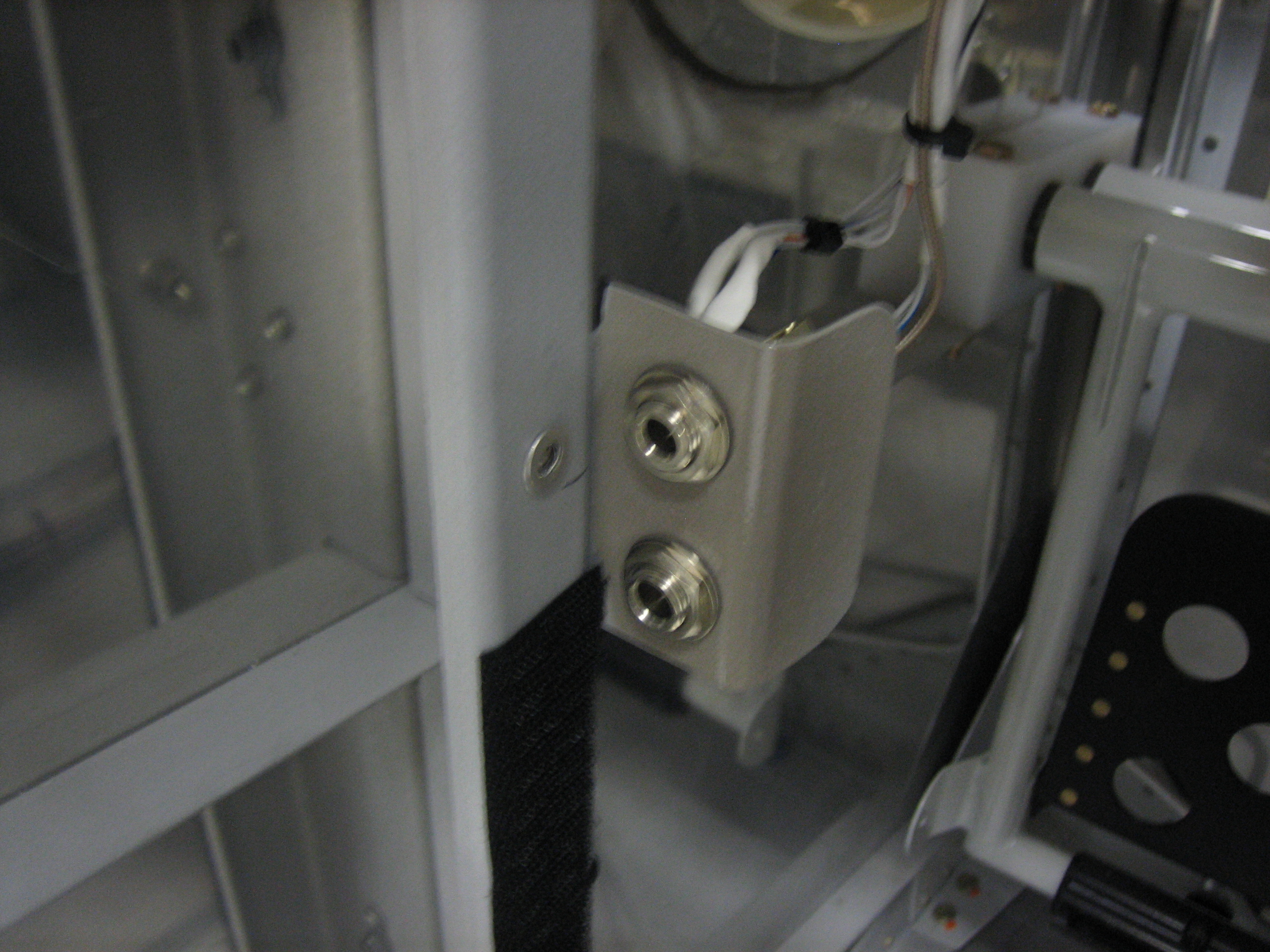
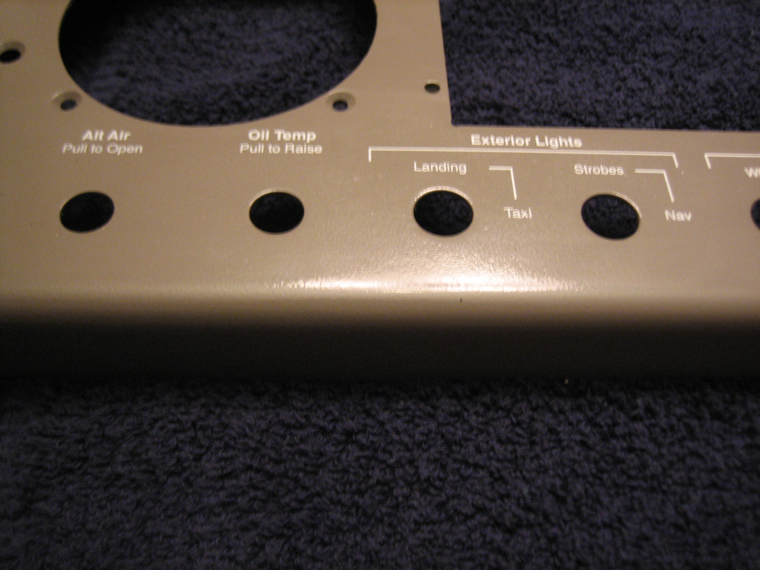
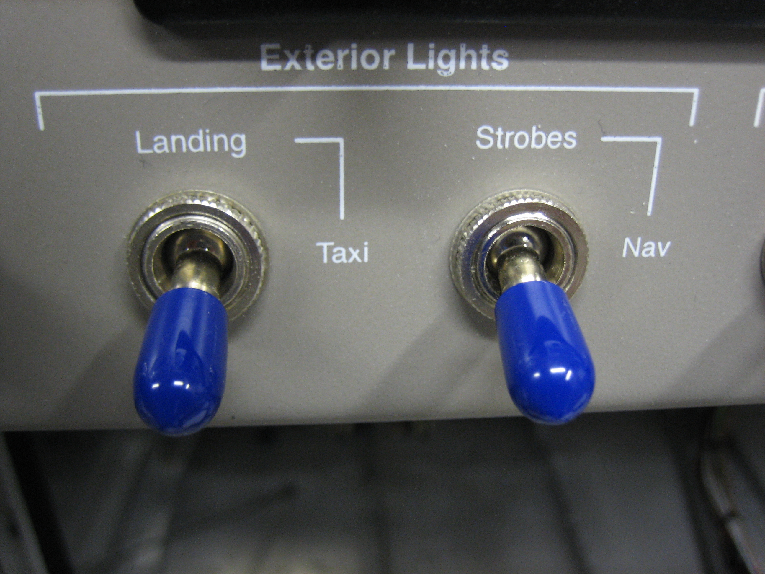
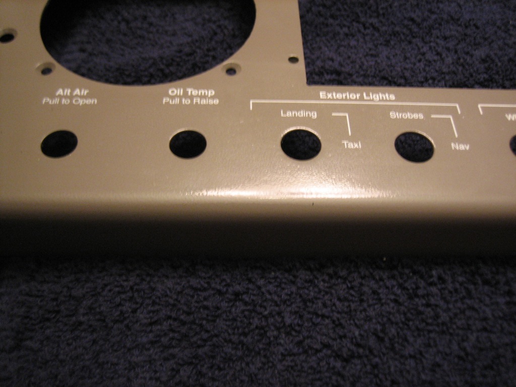
In the lower left, there are two spots for control cables to control the alt air and the oil cooler butterfly valve.  To the right of that are the exterior lights.

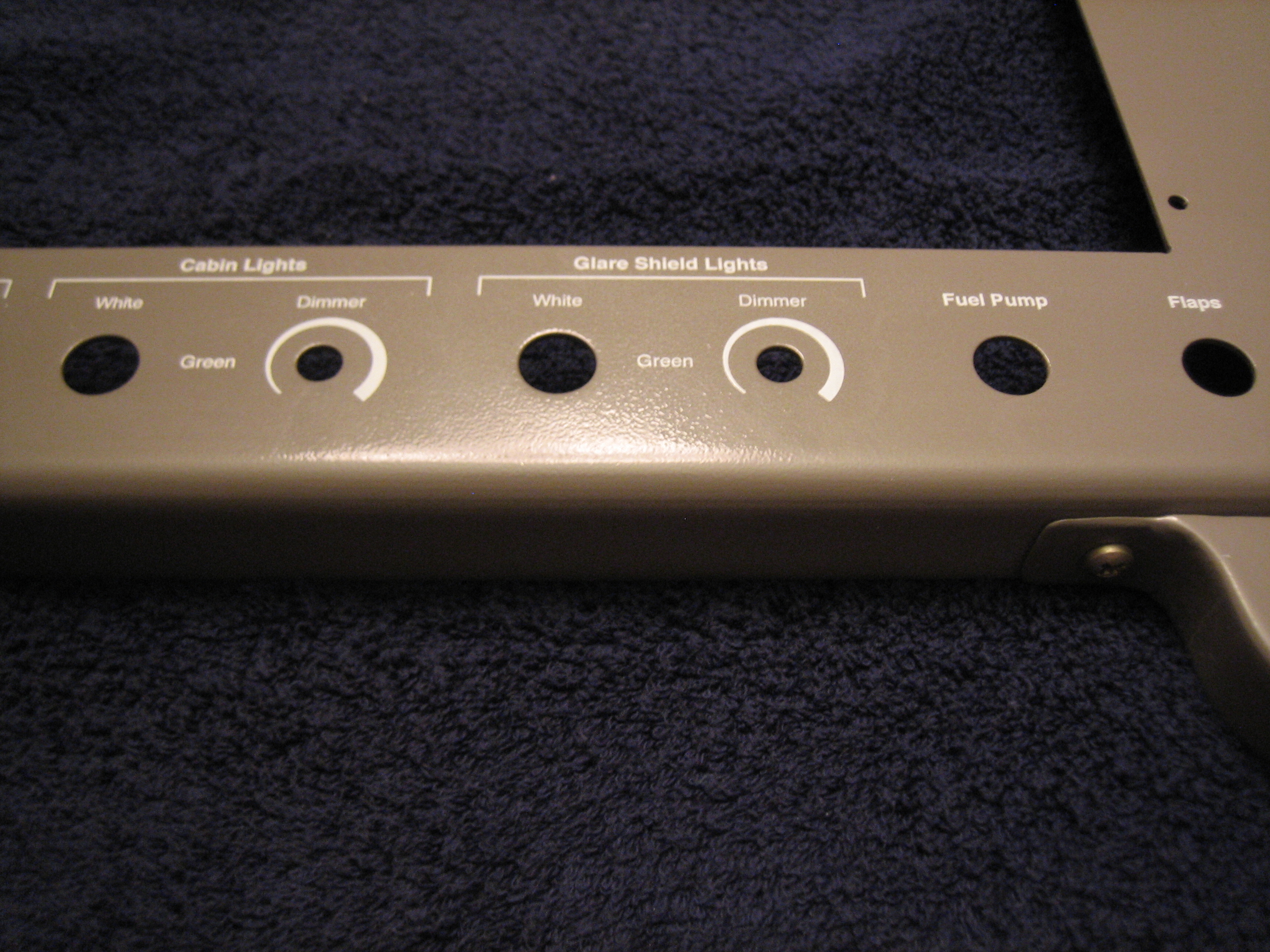
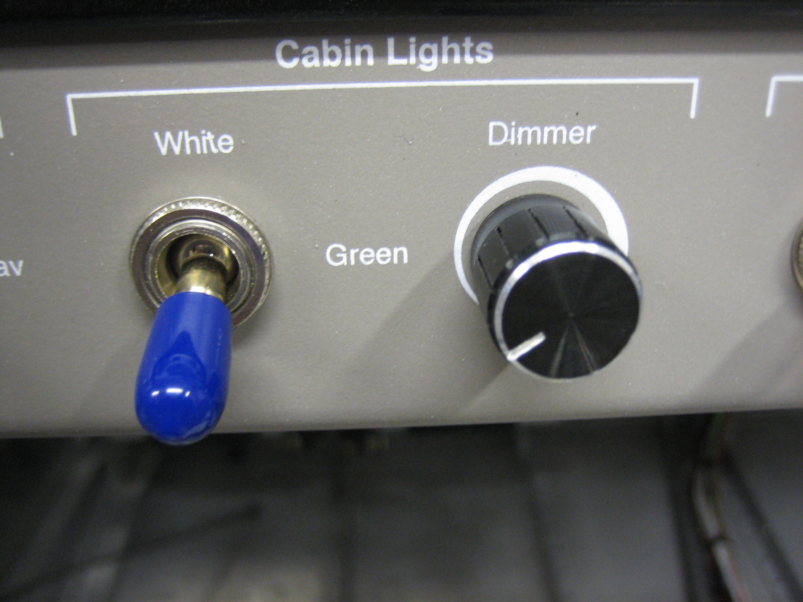
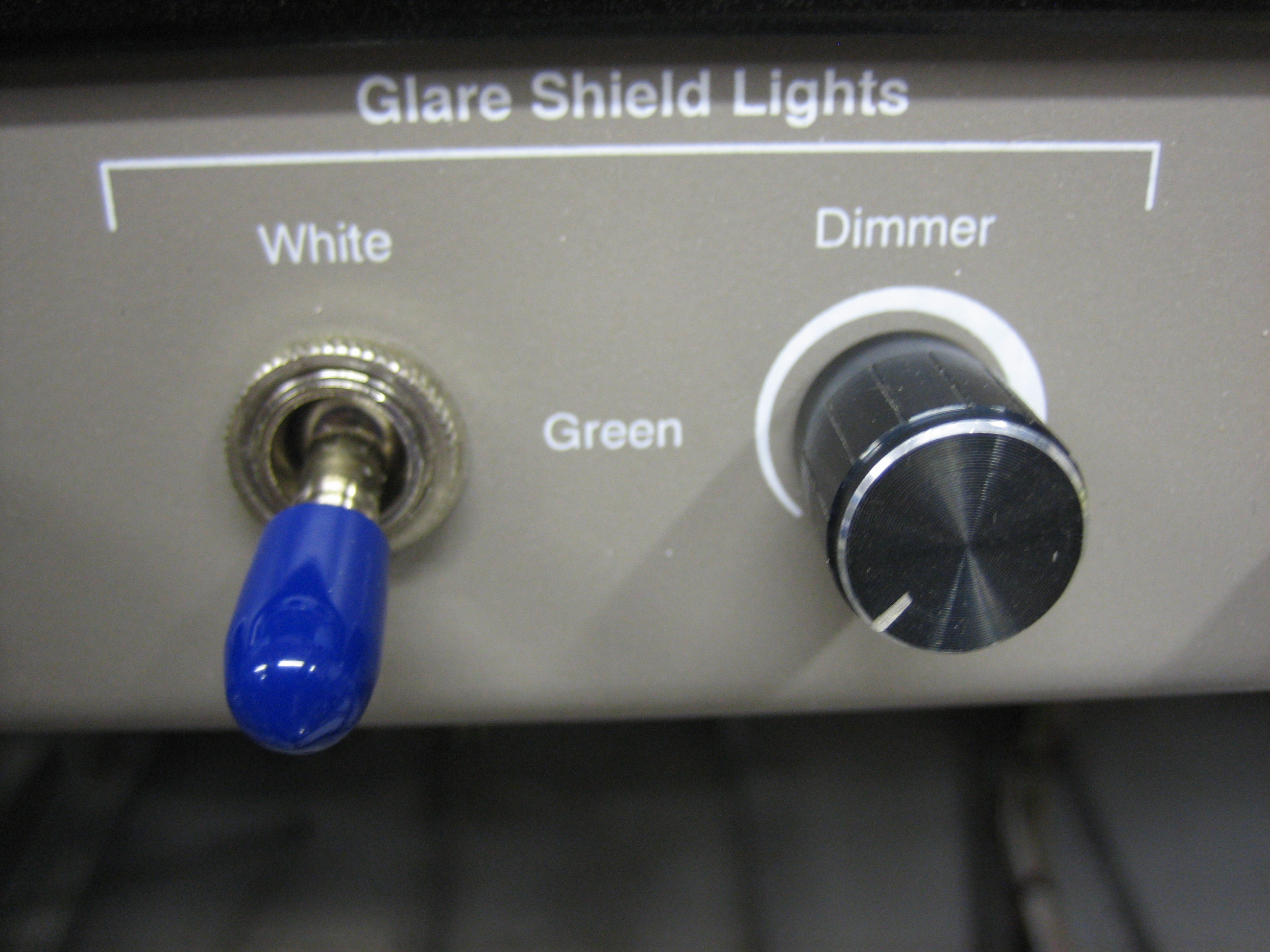
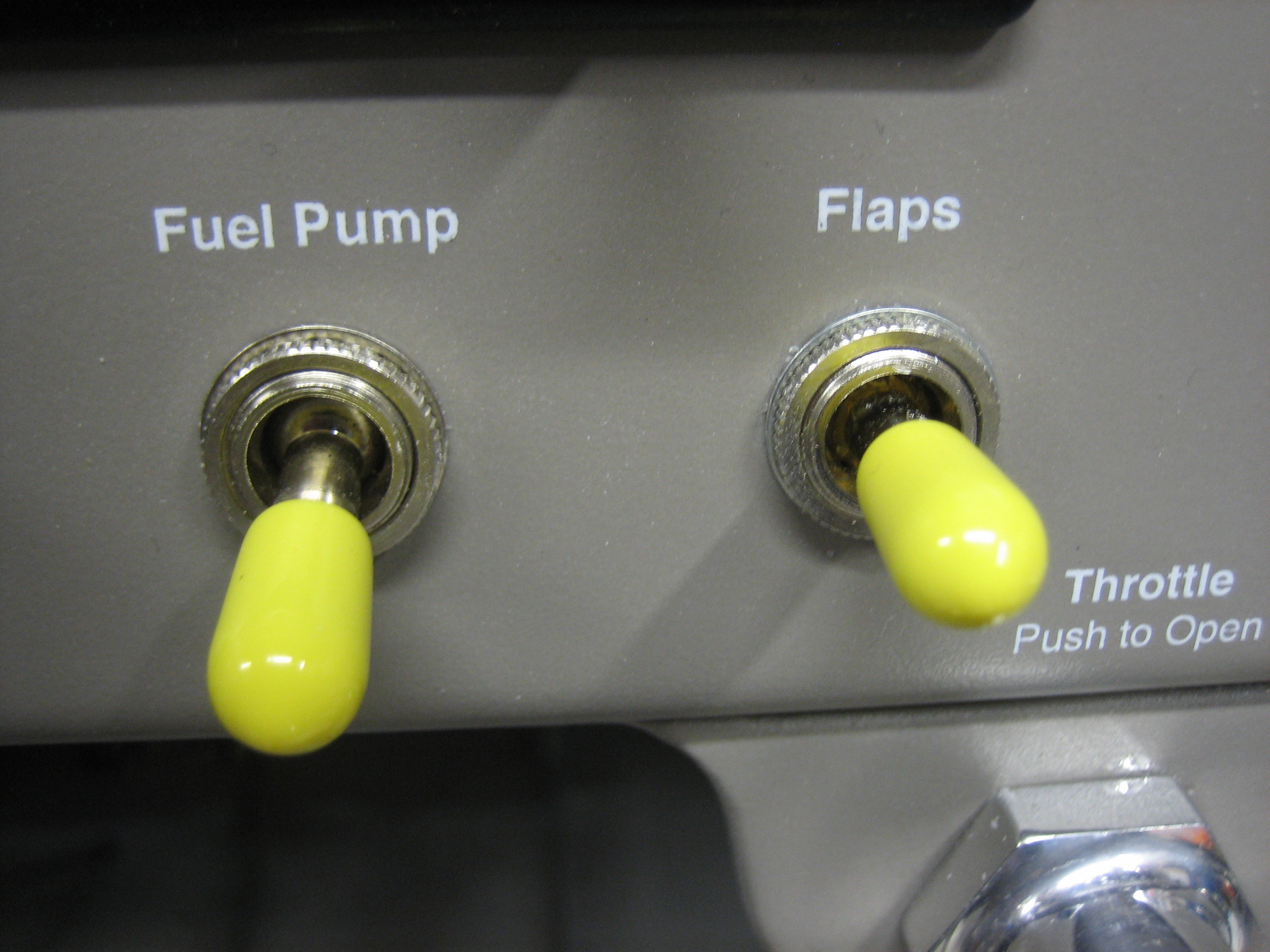
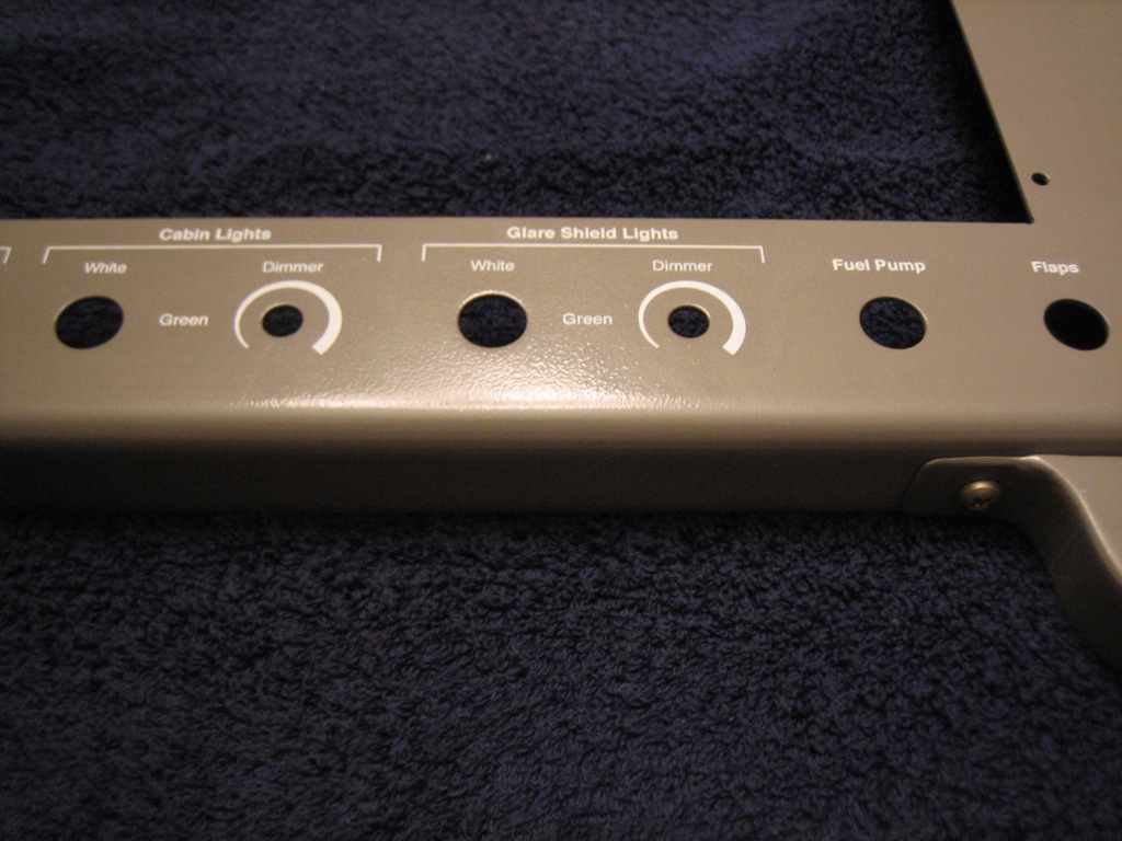
To the right of the exterior lights are two separate groups of interior lights.  Each can be set to either white or green light and has a dimmer.  Finally, the fuel pump and flaps switches round out the row.

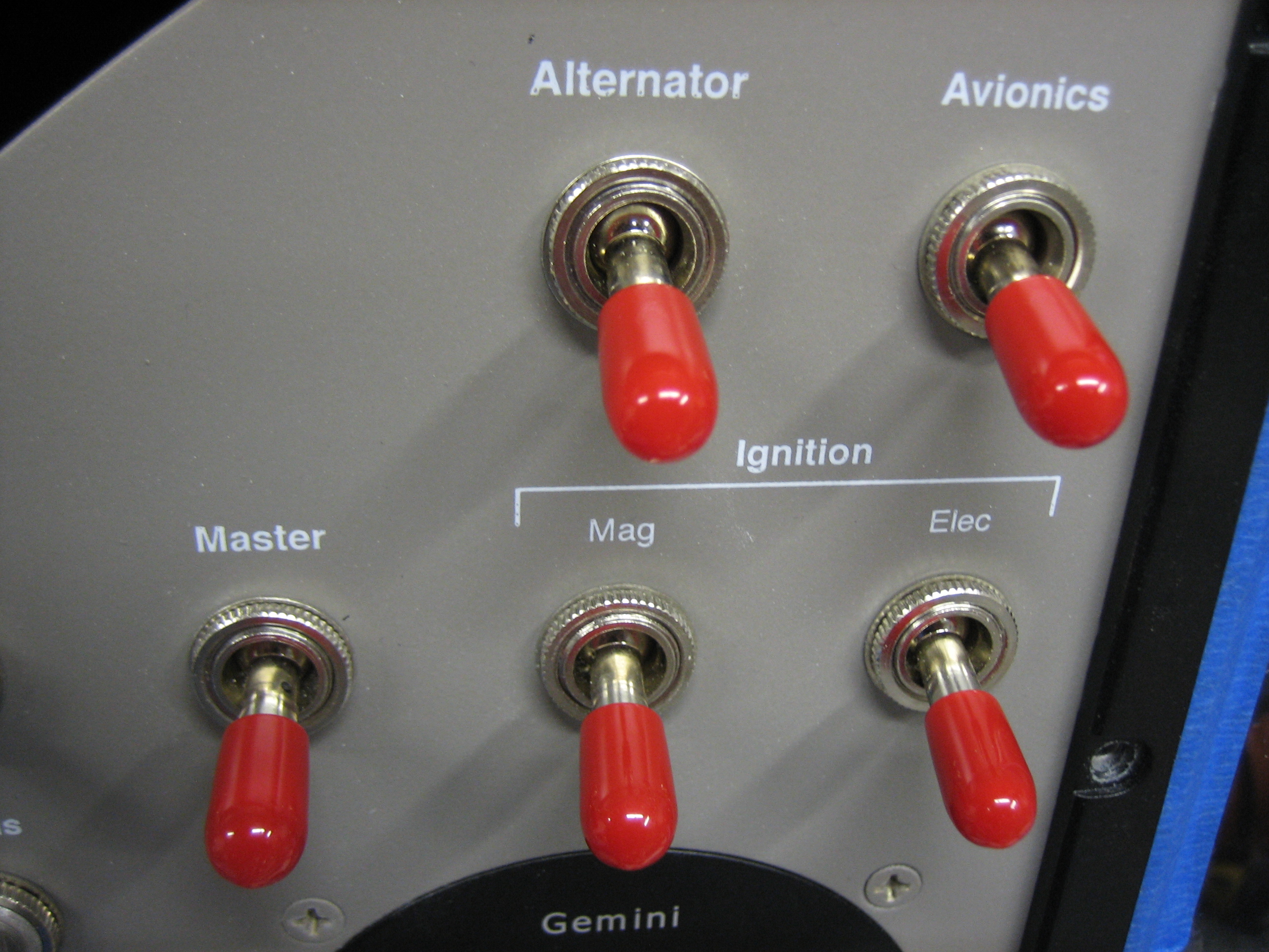
The engine controls and parking brake labels are on the main panel since I shortened the height of the control bracket.

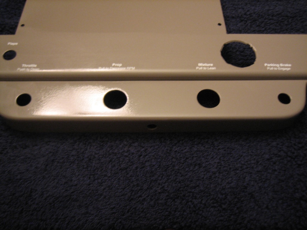
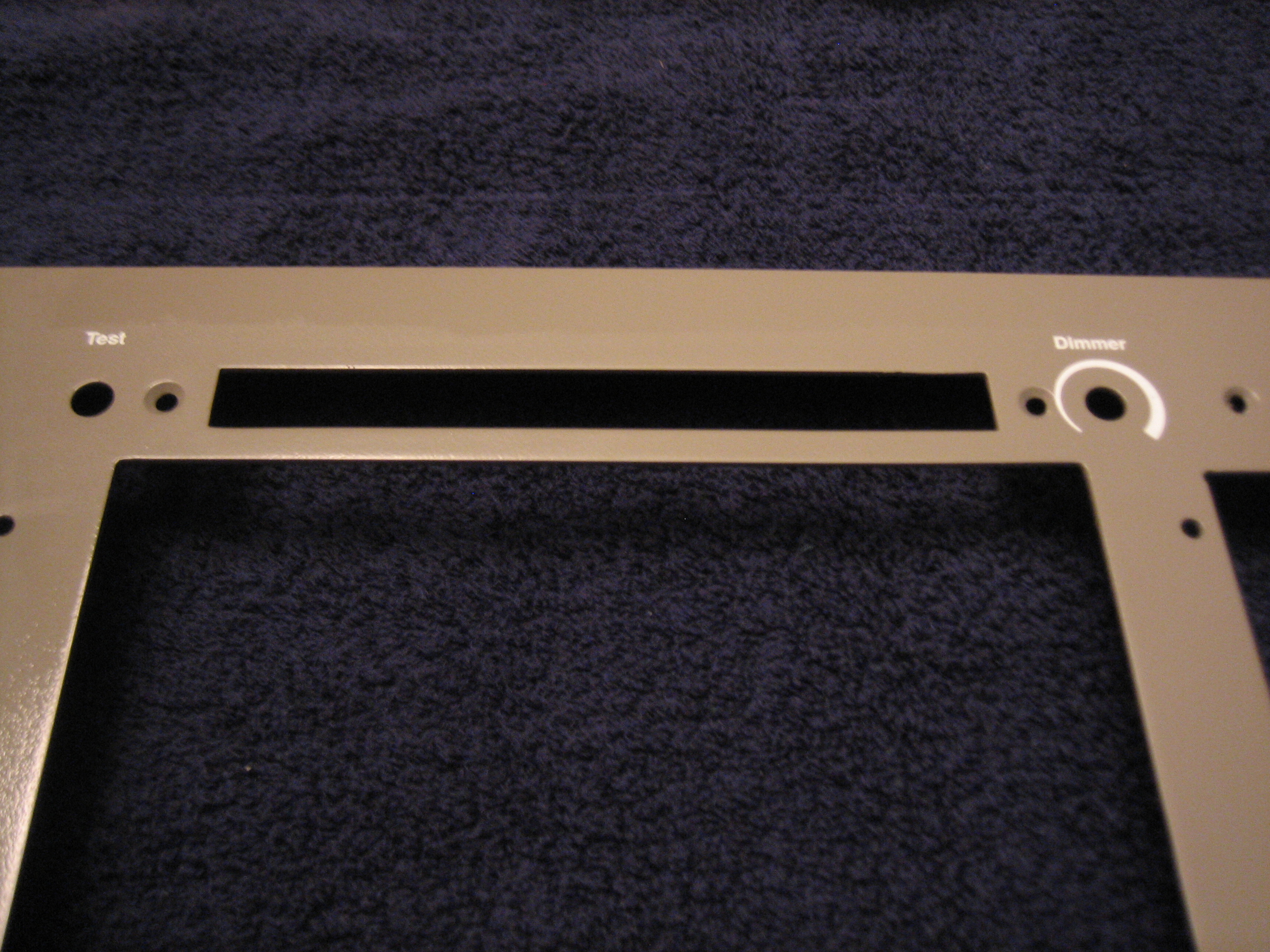
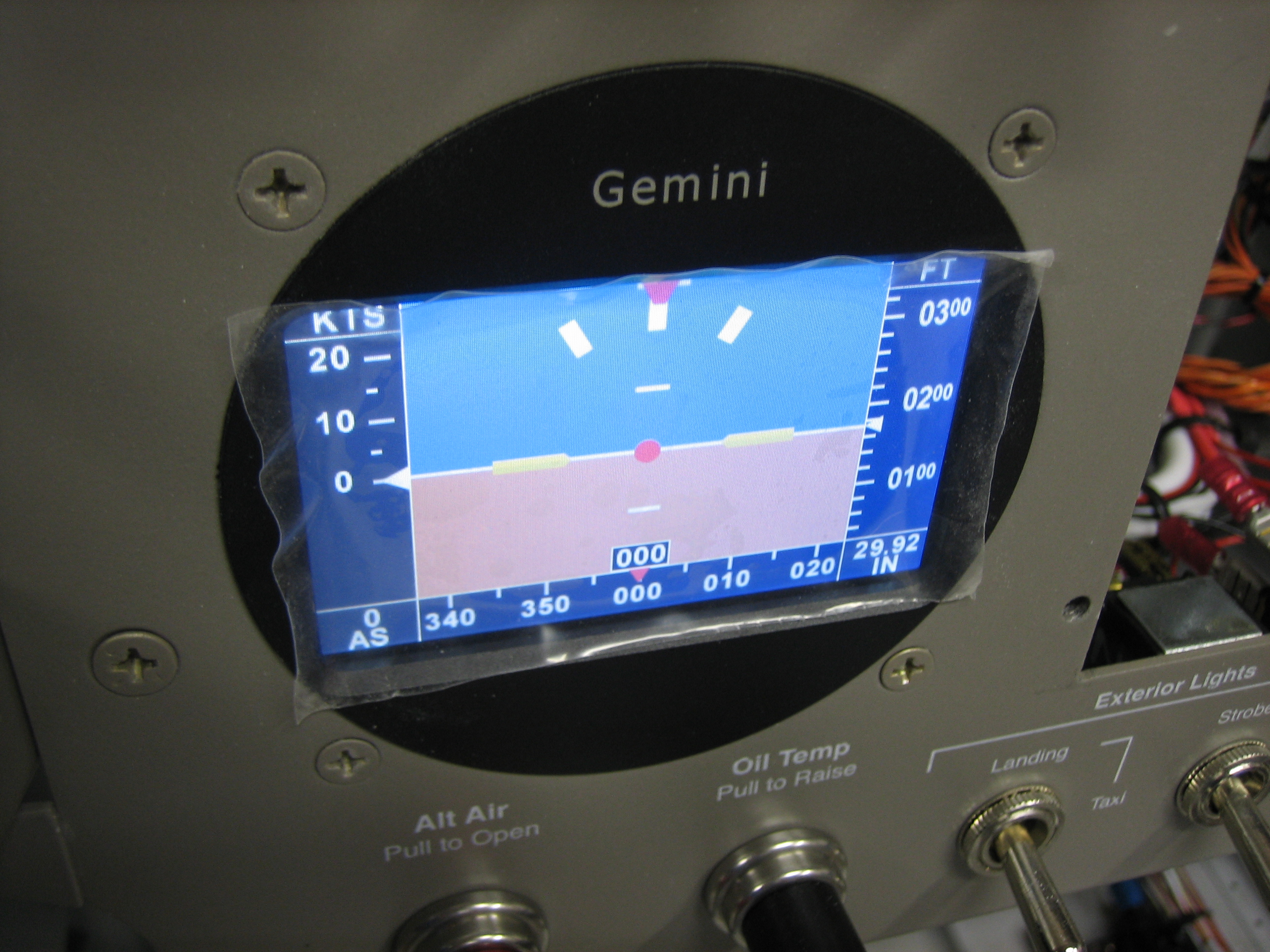
At the top of the radio stack are the test button for the annunciator lights and the dimmer which will dim both the annunciator lights and the TruTrak Gemini PFD (which unfortunately doesn’t have a light sensor and self-dimming capability).

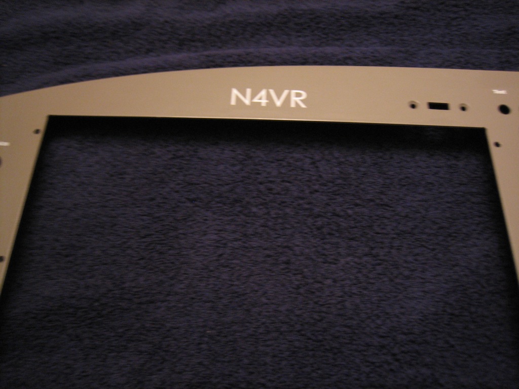
Above the pilot’s PFD is the tail number.

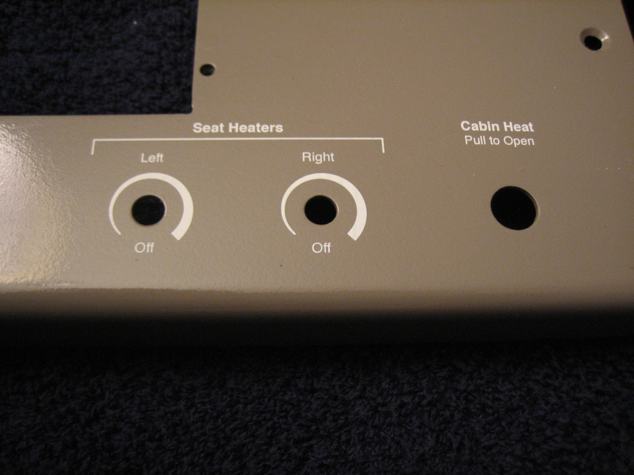
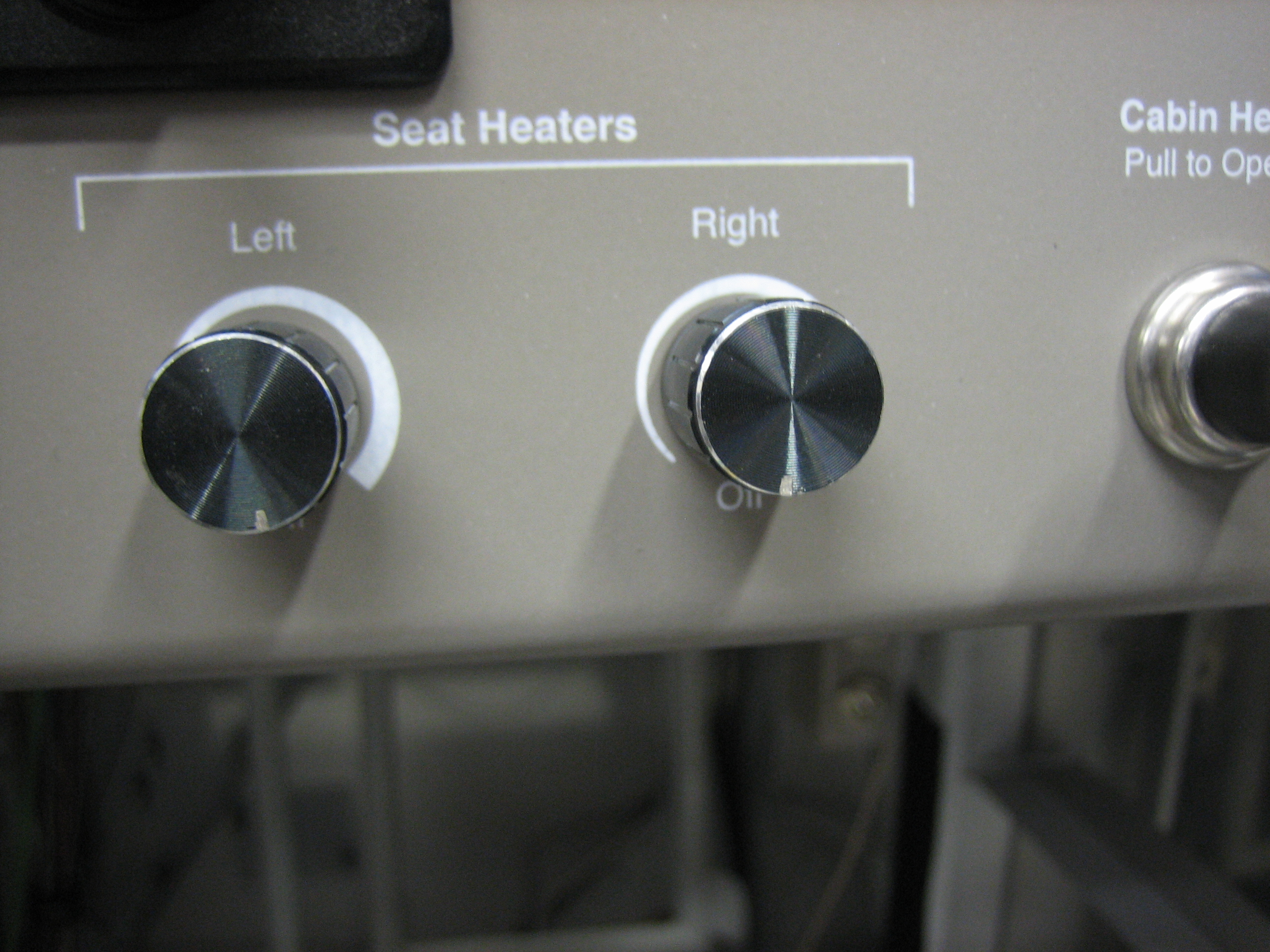
On the lower right of the panel is the controls for the seat heaters and cabin heat.

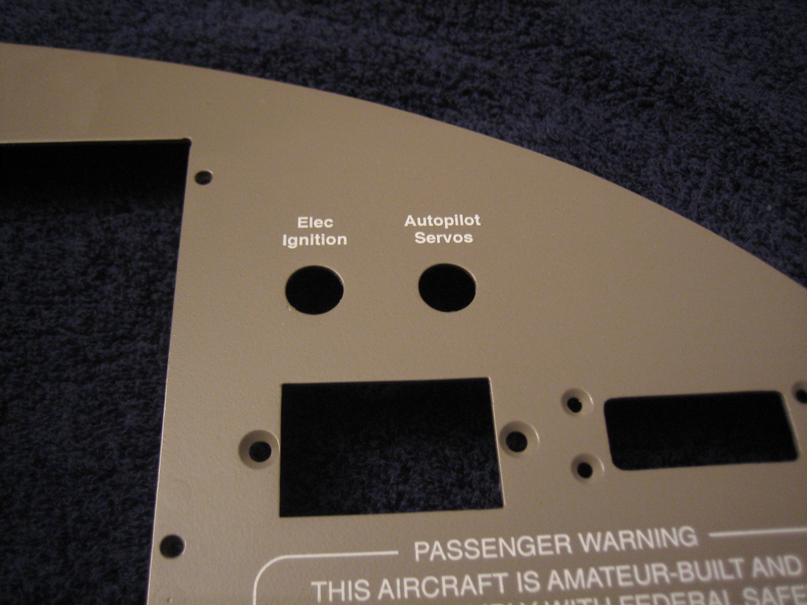
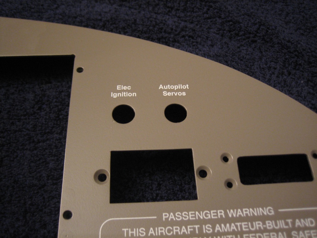
The top right has the only two breakers in the plane, pullable units for the electronic ignition and autopilot servos.

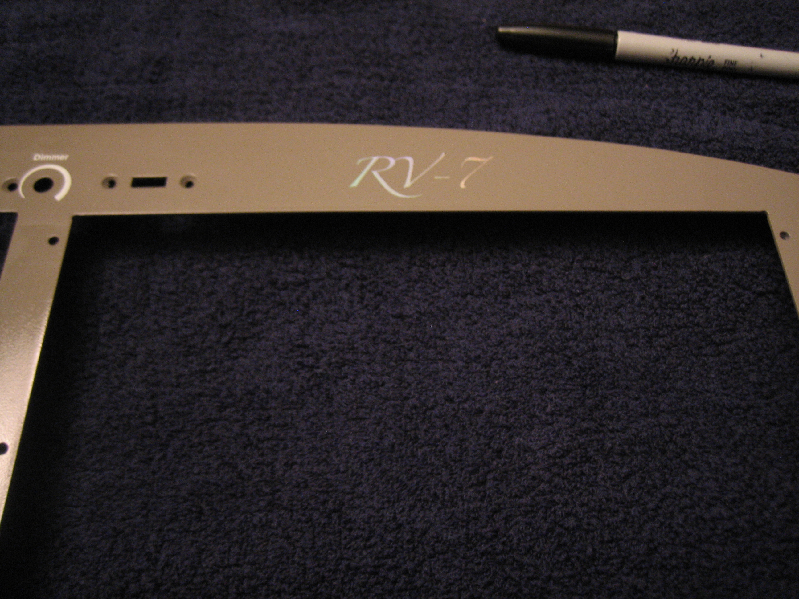
Above the copilot’s display is the RV-7 badge in the Zapfino font using a silver holographic foil.  The picture really can’t capture how this looks, but the color changes depending on the angle you view this from.  This would look tacky if you used too much of it, but it looks really sweet on just this one detail.

Started Reinstalling Panel

I shot some matte clear over the panel and let it cure for a couple of hours.  I then installed the panel and started installing components.  I got everything but the SkyView displays and radio stack installed for good.

I already ran all the wires for the TruTrak Gemini PFD, so I quickly wired it up and hooked up the pitot and static tubes.  I then reconnected the battery and turned on the avionics to check it out.  I still need to figure out the screen dimming, but that shouldn’t take too long.

Finished Instrument Panel

I installed the SkyView screens and radio stack and fired up the panel to make sure everything was working properly.

Next, I installed the control cables in the bracket and attached that to the bottom of the instrument panel.

I didn’t get a shot of this last night, but here’s the back of the Gemini PFD.  I still need to install a DB-9 connector shell, but this shot shows the pitot and static connections.  The green tubing is the pitot and the white tubing is the static.  This has to tee to go up to the alt static switch.

Here’s the alt static switch.  This opens the static tubing up to cabin pressure.

To wrap up the panel, I put switch boots on most of the switches.  All of these are marked red because switching any of them in flight could be critical.

All light switches are blue.  Here are the exterior lights.

The interior lights both have dimmers.  Here are the controls for the cabin lights which are mounted in the roll bar support.

Here are the glare shield lights.

The fuel pump and flaps have yellow boots because operating them should be done with caution.

Here are the completed seat heater controls.  The cabin heat control is just to the right.

Started Installing Control Cables

I started wrapping up the control cable installation tonight.  First up is the cable supports on the subpanel.  Attaching these stiffened up the control bracket quite a bit, but there’s still a bit of flex.  I may add a stiffener between the control bracket and the subpanel.

This is the forward end of the control cable.  I replaced the undrilled bolt with all metal lock nut that is specified in the plans with a drilled bolt, castellated nut, and cotter pin.  I’m doing that on all bolts used in the engine control cables.

Here’s the forward end of the throttle cable.  All adjustment nuts have been torqued and sealed.

Here’s the firewall penetration for the throttle cable.  This is installed for good.

Here’s the finished attach end of the mixture control cable.  All linkages have been adjusted and cotter-pinned.

I had to adjust the bracket attach on the control cable to the far forward end of the threads.

The mixture cable firewall penetration on the left is done.  The prop governor penetration on the right is still loose until I get everything adjusted.

Installed Parking Brake and Cabin Heat Control Cables

I reinstalled the parking brake cable and all of the adel clamps that secure it.

Here’s the valve end.  Removing this adel clamp requires removing the electronic ignition box.  Hopefully, I won’t have to do that much.

The cabin heat control cable arcs over the rudder pedal torque tubes and is anchored to one of the firewall stiffeners before heading towards the center of the cabin.

The end of the cable housing is anchored with another adel clamp using the bolt that attaches the heater box.