Finished Fabricating Outer Baffle Connecting Rods

I finished fabricating the outer baffle connecting rods.  Here’s the one on the left side of the engine.

I put a fairly healthy curve in the rods.  This way they stay fairly straight even under tension.

Here’s the one on the right side of the engine.  Both outer rods touch the cylinder head oil return lines, but the curve I put in the rods causes it to just touch the oil line, not put pressure on it.  That plus the plastic cover on the rods should eliminate any abrasion on the oil lines.

Finished Baffle Connecting Rods and Started Snorkel

I finished up the inner baffle connecting rods.  Here’s the one on the left side of the ending.  Getting to the nut on the aft end of this rod is probably the toughest part of installing these.

And here’s the inner connecting rod on the right side of the engine.

Next, I got started fitting the snorkel.  The engine air inlet on this engine is in the front left ramp.  The air will flow through an air filter and then down through the snorkel and into the fuel injection servo here.  I took off the cover plate and measured the size of the hole.

The hole in the snorkel is 2.400″.  I took a roll of electrical tape and added some masking tape until this was just under that size.

I then taped the roll of tape to the front of the servo so that I could temporarily fit the snorkel.

The aft face of the snorkel isn’t sitting flush with the face of the fuel injection servo.

This is part of the problem.  The lower right lug on the starter is interfering with the snorkel.

And this is the rest of the problem.  Because of the shape of the snorkel, it interferes with the alternator mount.

I took a cutoff saw and removed most of the offending starter lug.  I’ll probably end up pulling the starter and removing the entire lug or lugs once I know for sure which ones need to be trimmed.

I also roughed out the cutout that needs to be made to clear the alternator mount.

I ended up having to cut even more from the snorkel to clear the alternator bracket.  I’ll cover this with glass once I know the final shape.

Finally, I spent a little time trimming the top of the snorkel.  I still have a bit more to do to shift the opening far enough inboard to clear the conical gussets.

Modified Starter

I pulled the starter off the engine and filed off the two lower lugs to provide clearance for the snorkel.

You can see here that with the snorkel in place and the lugs gone, there is right at 1/8″ of clearance between the starter and the snorkel.  This is the minimum clearance specified by the plans, and I needed to get it this tight to allow the snorkel to swing up far enough to place the inlet in the best part of the ramp.

Fit Snorkel to Fuel Injection Servo

With the snorkel in it’s final location, I marked the flange along the edges of the servo and cut them off.

I then drilled the flange for some 1/4″ hardware and temporarily bolted the snorkel in place.  I still need to do some trimming at the upper end to provide room for the filter.

Fit Air Filter Mounting Flanges to Snorkel

I trimmed the air filter mounting flanges and drilled them to the snorkel.  The 3/8″ clearance turned out to be perfect if you tuck the closest bend on the flanges up against the top edge of the snorkel.  This provides just enough room for the flanges to sit below the inlet ramp and lay flat.  The inlet ramp will need a bunch of modification before this can be fitted.  I hadn’t read through the snorkel instructions before fitting the left side conical gusset.  It turns out that this isn’t supposed to be used when installing the snorkel.  I’m going to leave it in place though since the alternate design won’t seal tightly against the cowl inlet.

Here’s how the air filter will sit in the top of the snorkel.  I’ll need to cut most of the inlet ramp away to allow air into the filter.

Drilled Ramp for Alternator Cooling Blast Tube Flange

I’m going to be installing a cooling blast tube for the alternator.  I drilled a 5/8″ hole in the right ramp just above the alternator.

I purchased a couple of these flanges for 3/4″ SCAT tubing from someone on Van’s Air Force.  I put a socket inside the flange to help center it in the hole.

Here’s where the flange will mount on the bottom of the ramp.

I wrapped a few layers of electrical tape around the socket to perfectly center it in the hole since the fit was a little loose.  This worked like crap, don’t even bother.  I ended up having to drill new holes in the flange because it was so far off center.  Instead, just eyeball it and clamp it in place.  That worked perfectly.

Fit Snorkel to Inlet Ramp

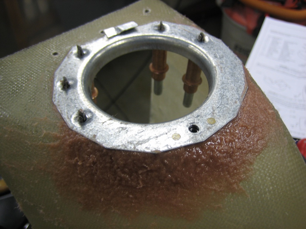
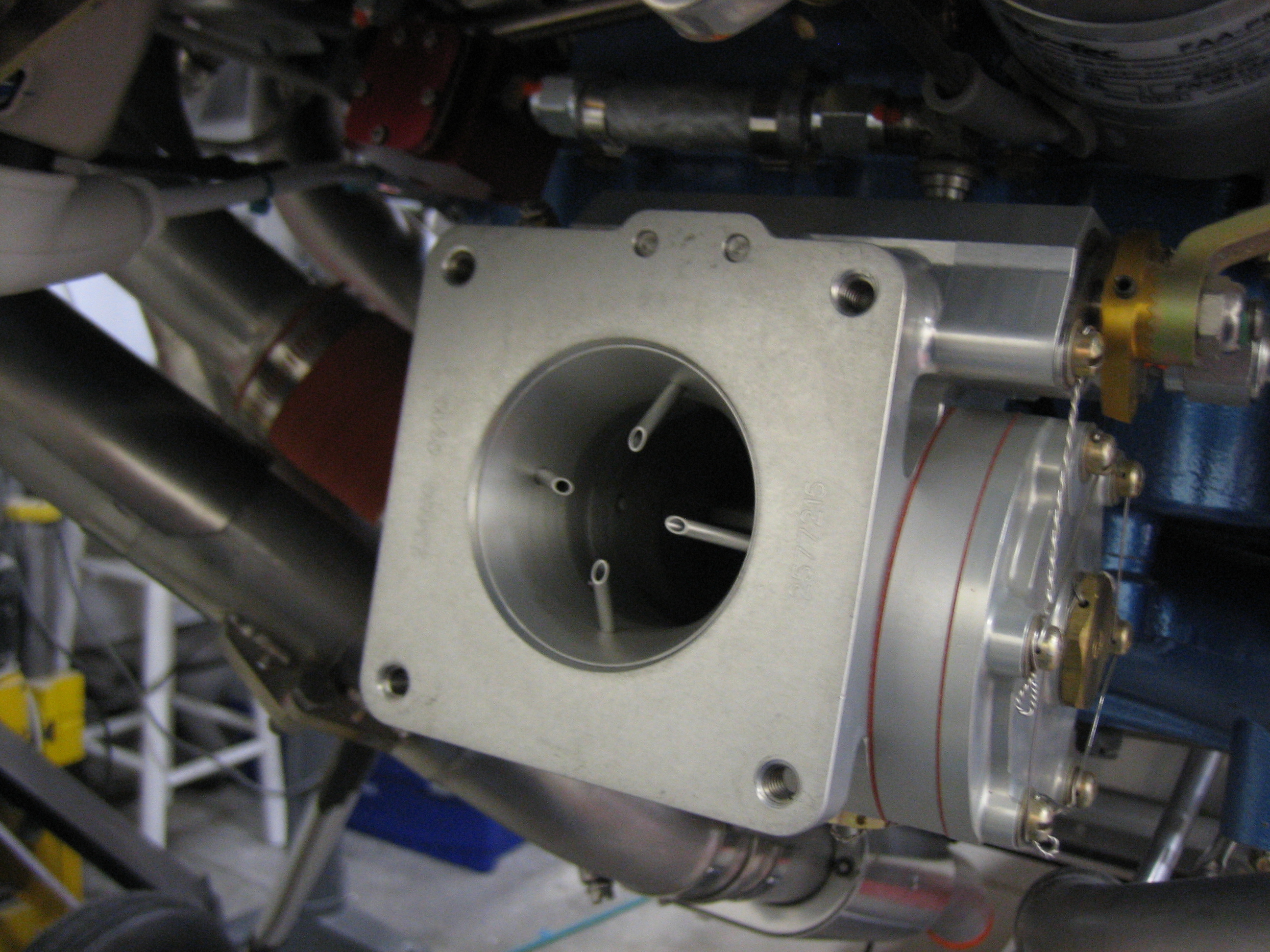
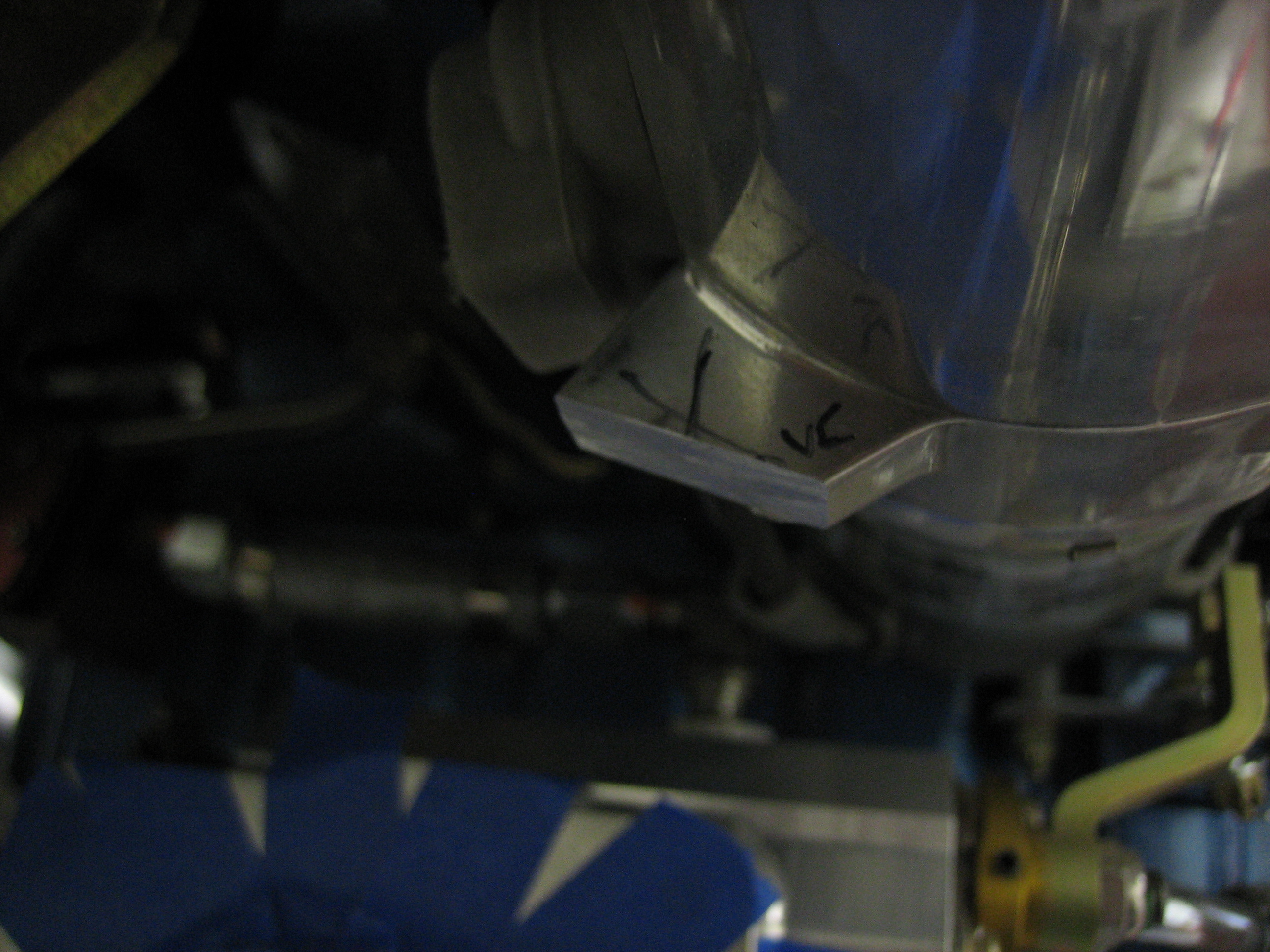
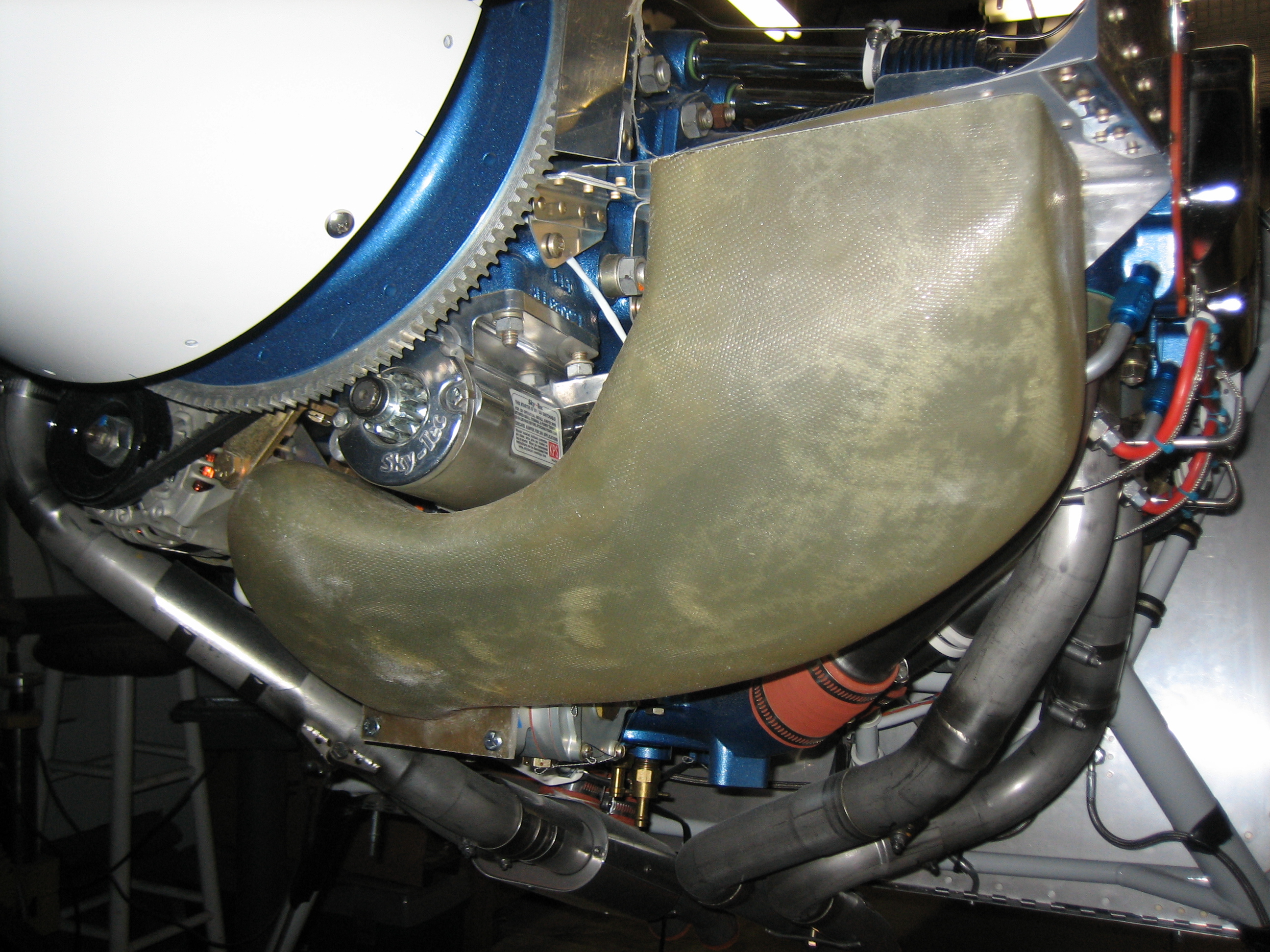
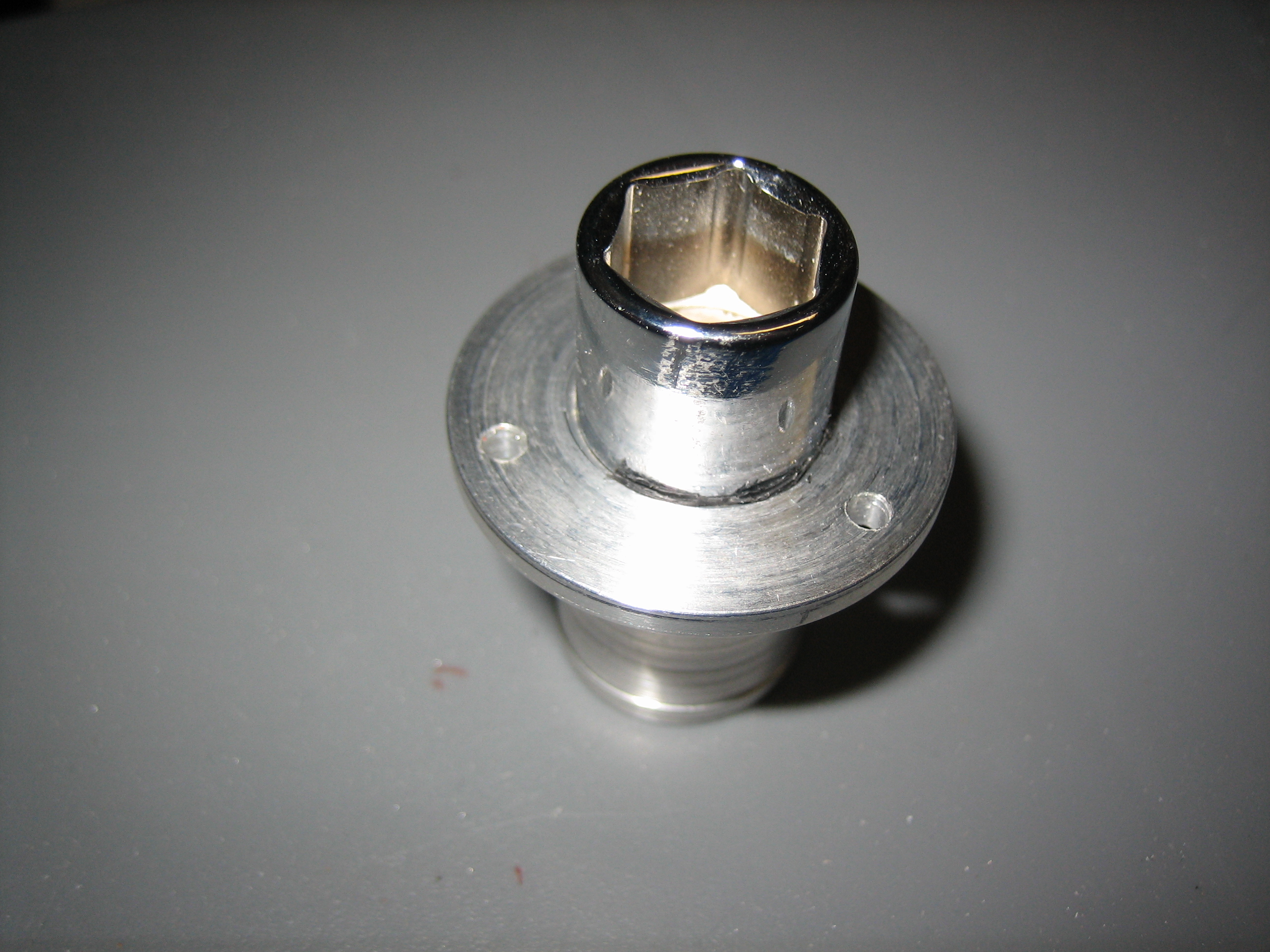
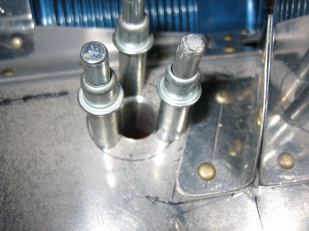
I meant to post this a few days ago, but here’s the flange nicely centered in the hole.  I picked up some aluminum screen material to rivet between the ramp and flange to keep out bugs and debris.

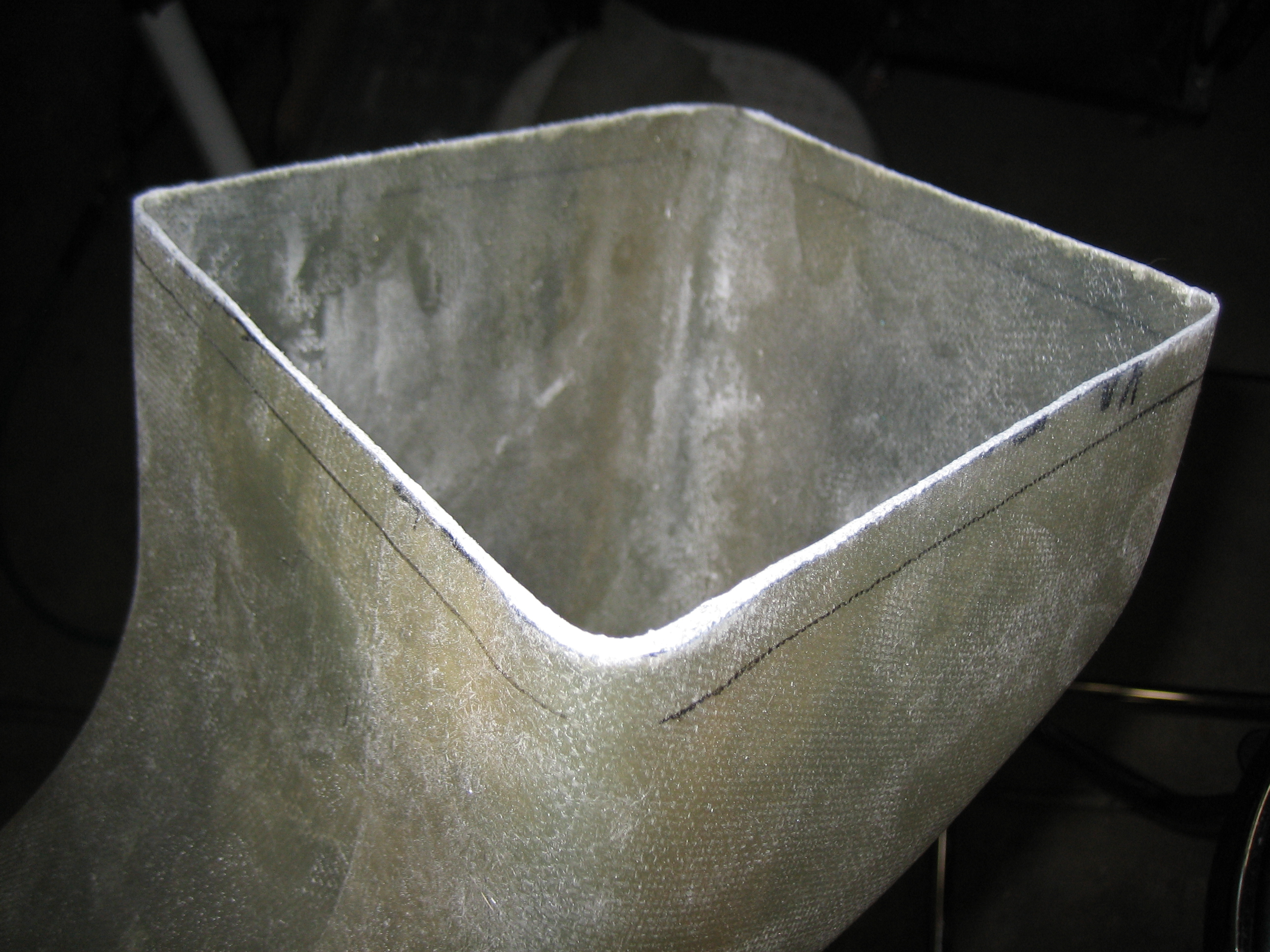
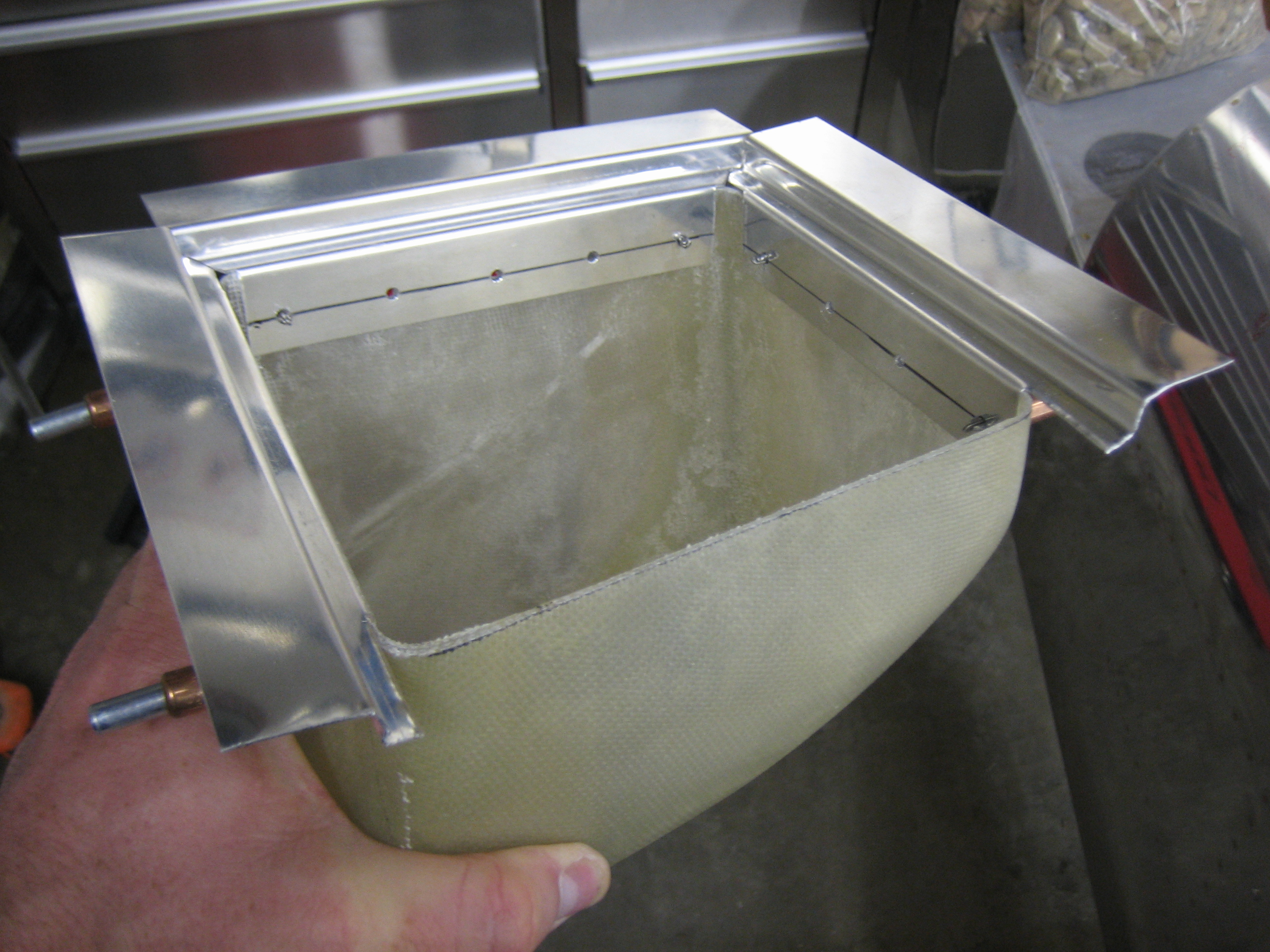
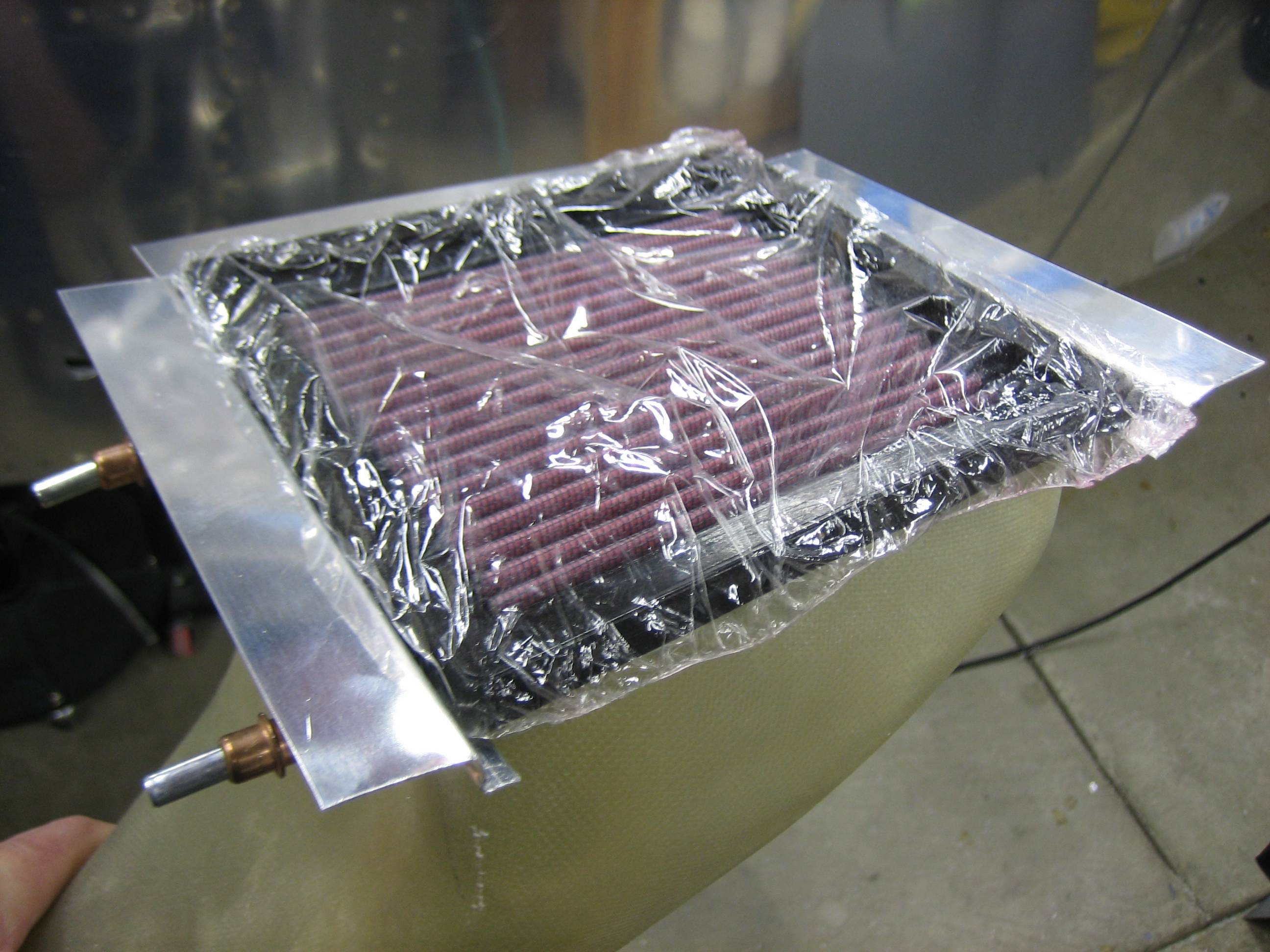
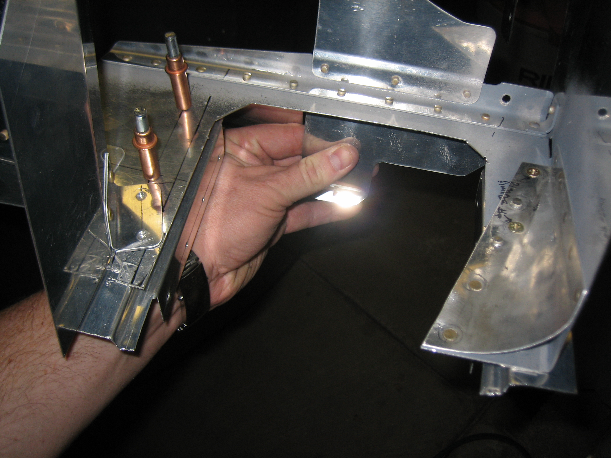
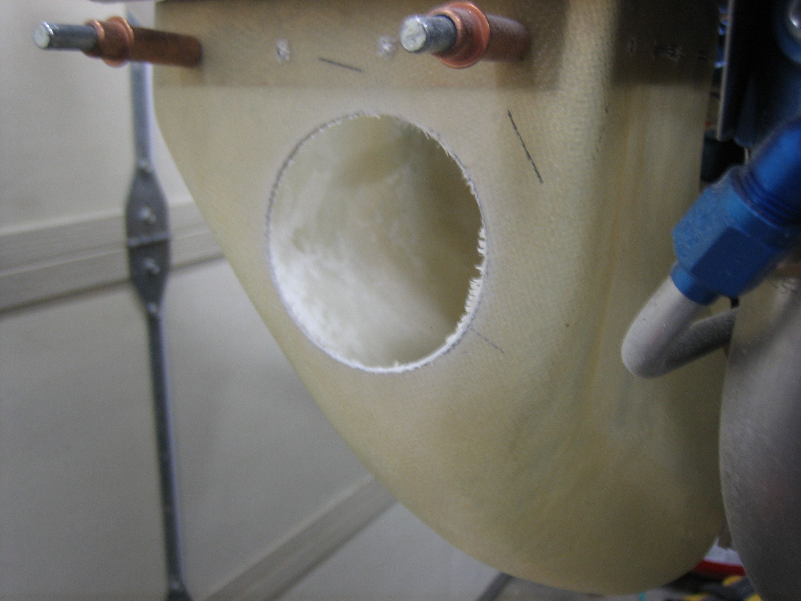
I cut out the opening for the air filter.  This is significantly undersized and the opening will be made large enough to install the air filter from the top.

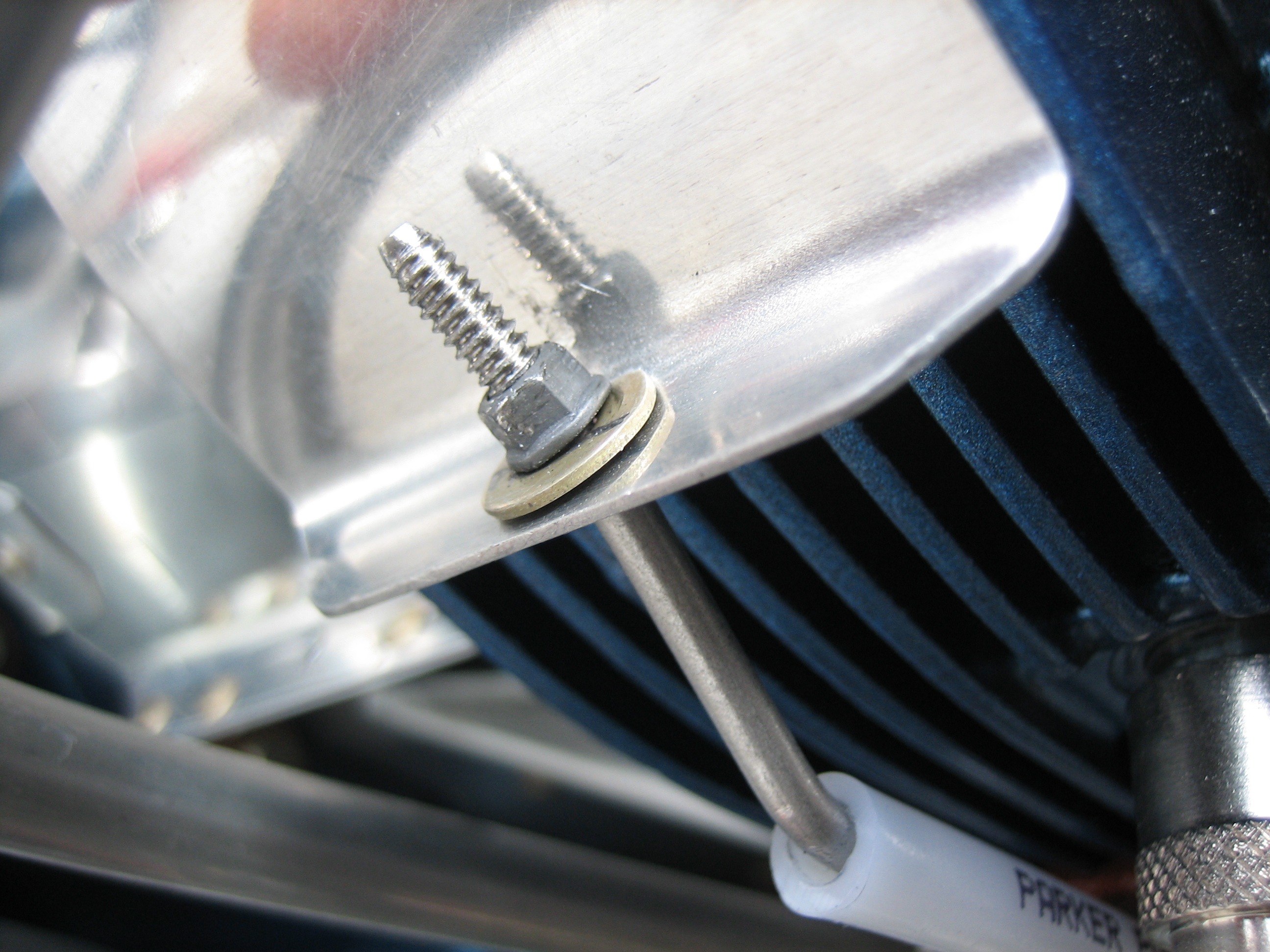
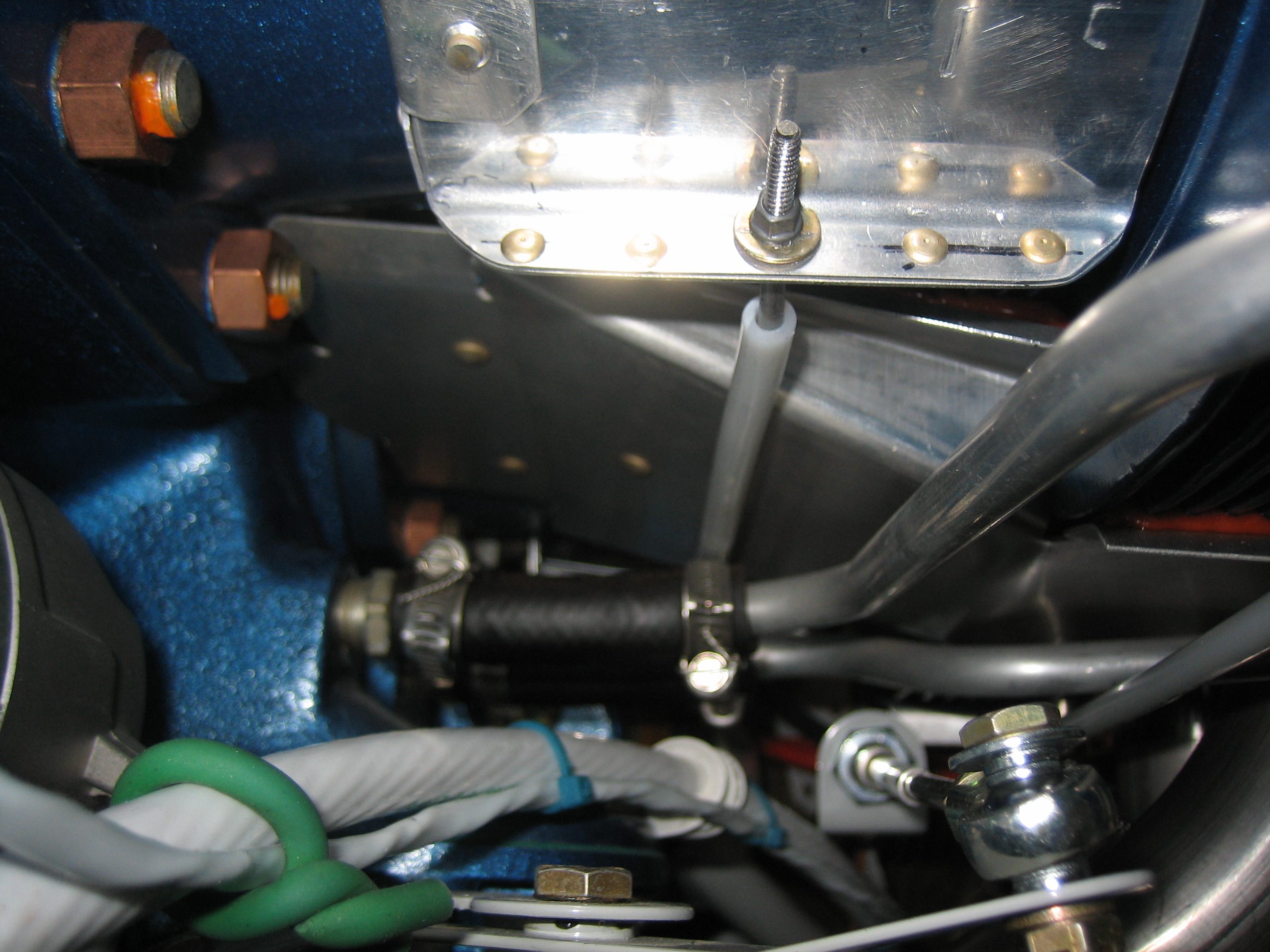
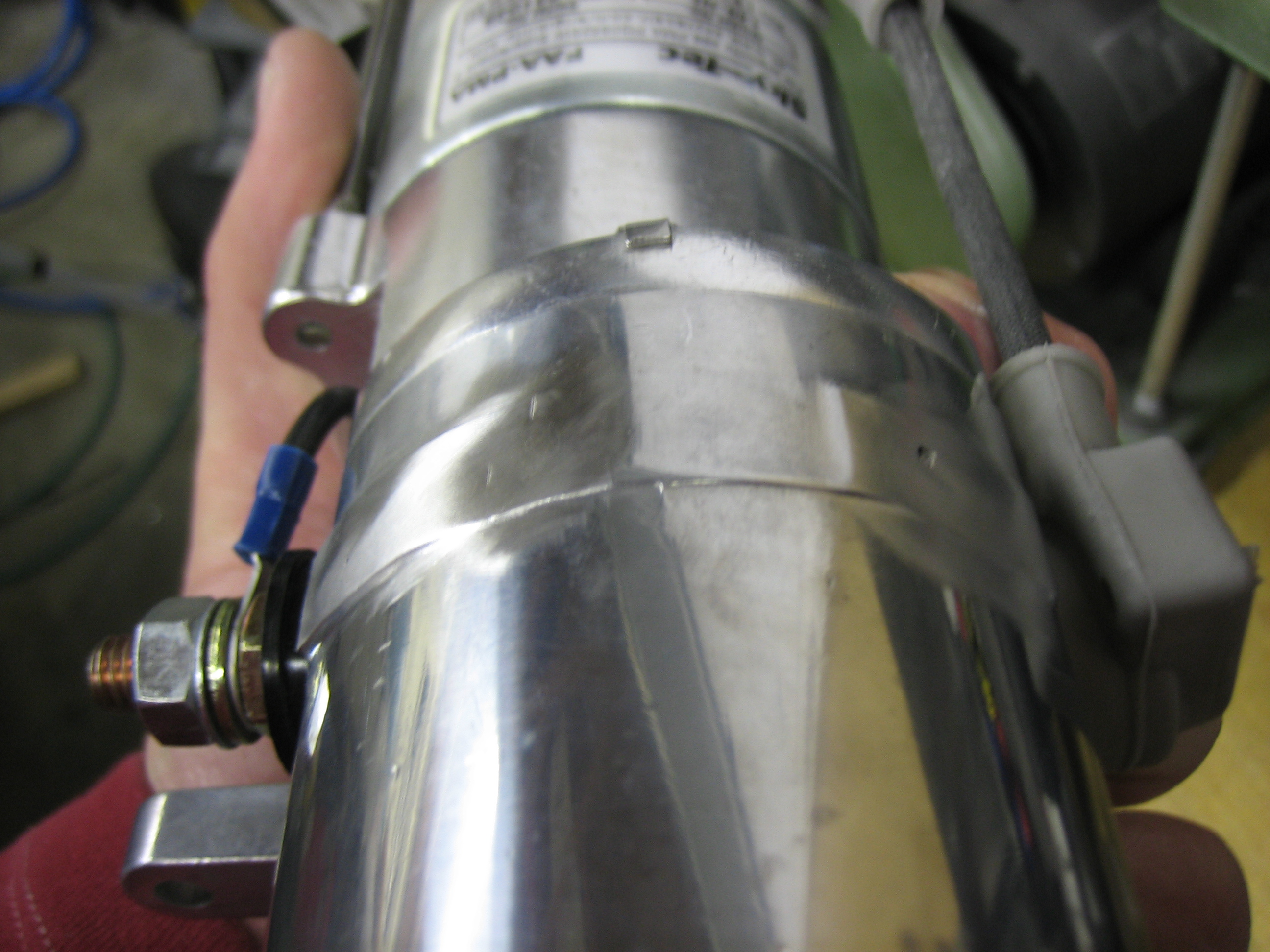
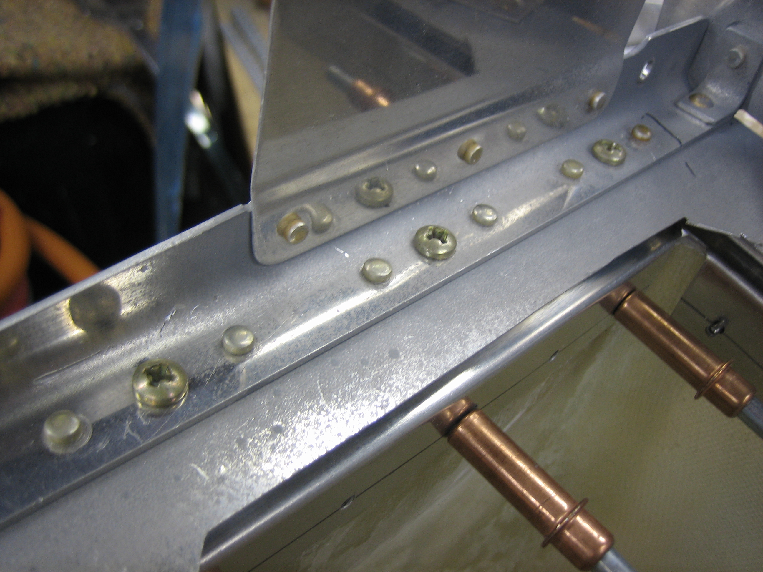
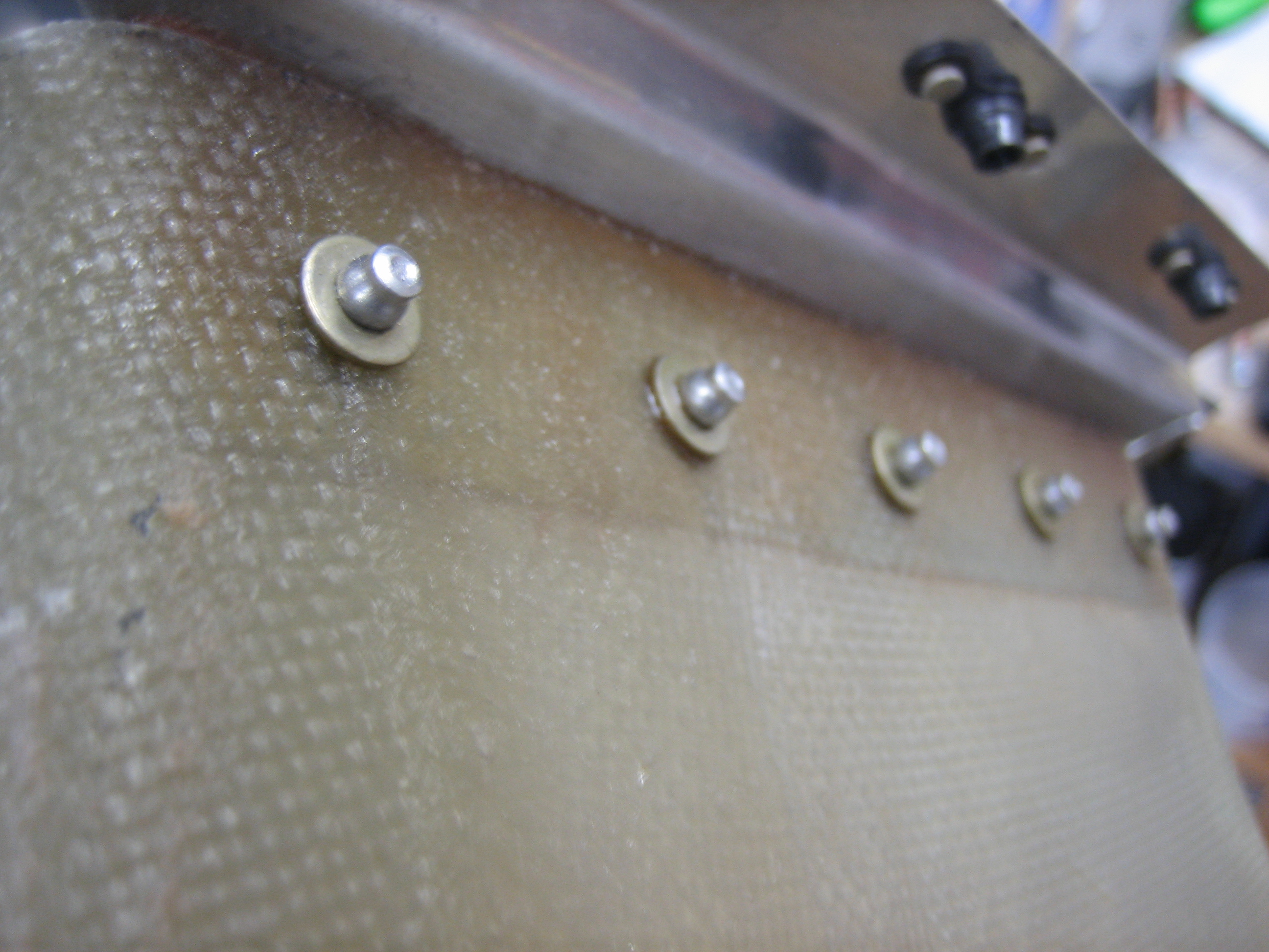
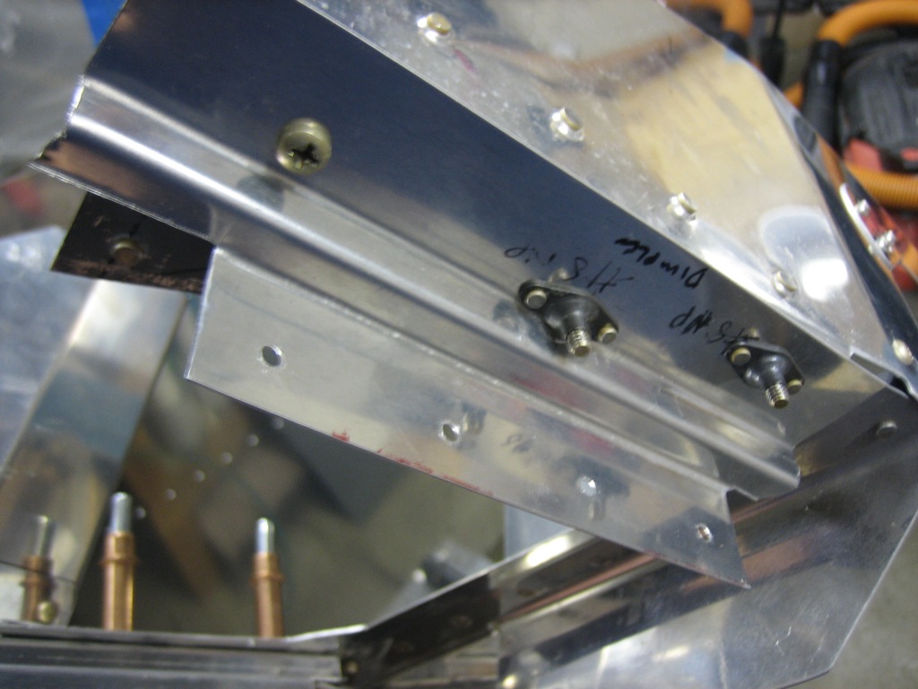
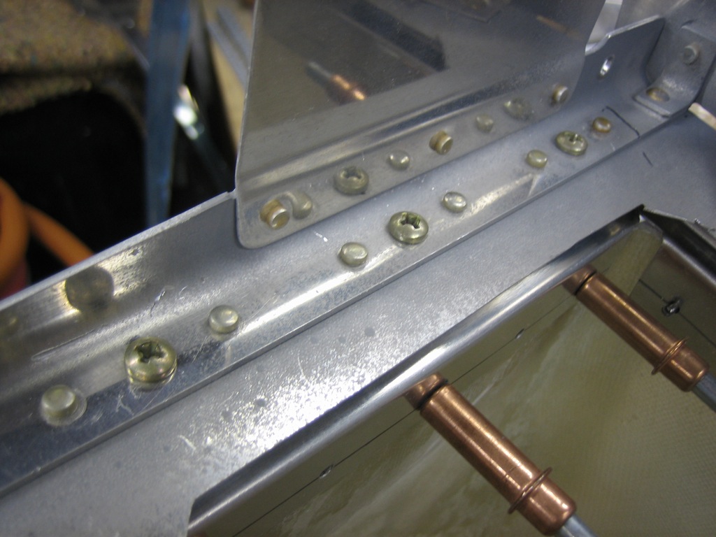
I then reworked the conical gusset a bit.  This is not normally installed with the snorkel, but I really didn’t like the way the cowl inlet intersection worked without it, so I’m going this route.  The edge of the gusset will cover up a very small amount of the filter, but there will be enough of a gap that air can still flow through the entire filter.  I replaced the aft most rivet in the gusset with an AN515-8R8 screw that goes through the ramp and snorkel mounting flange.  I added a second screw between the next two rivets forward (which both had to be reversed so that the flush head is on the bottom so that the shop heads don’t interfere with the filter flange).

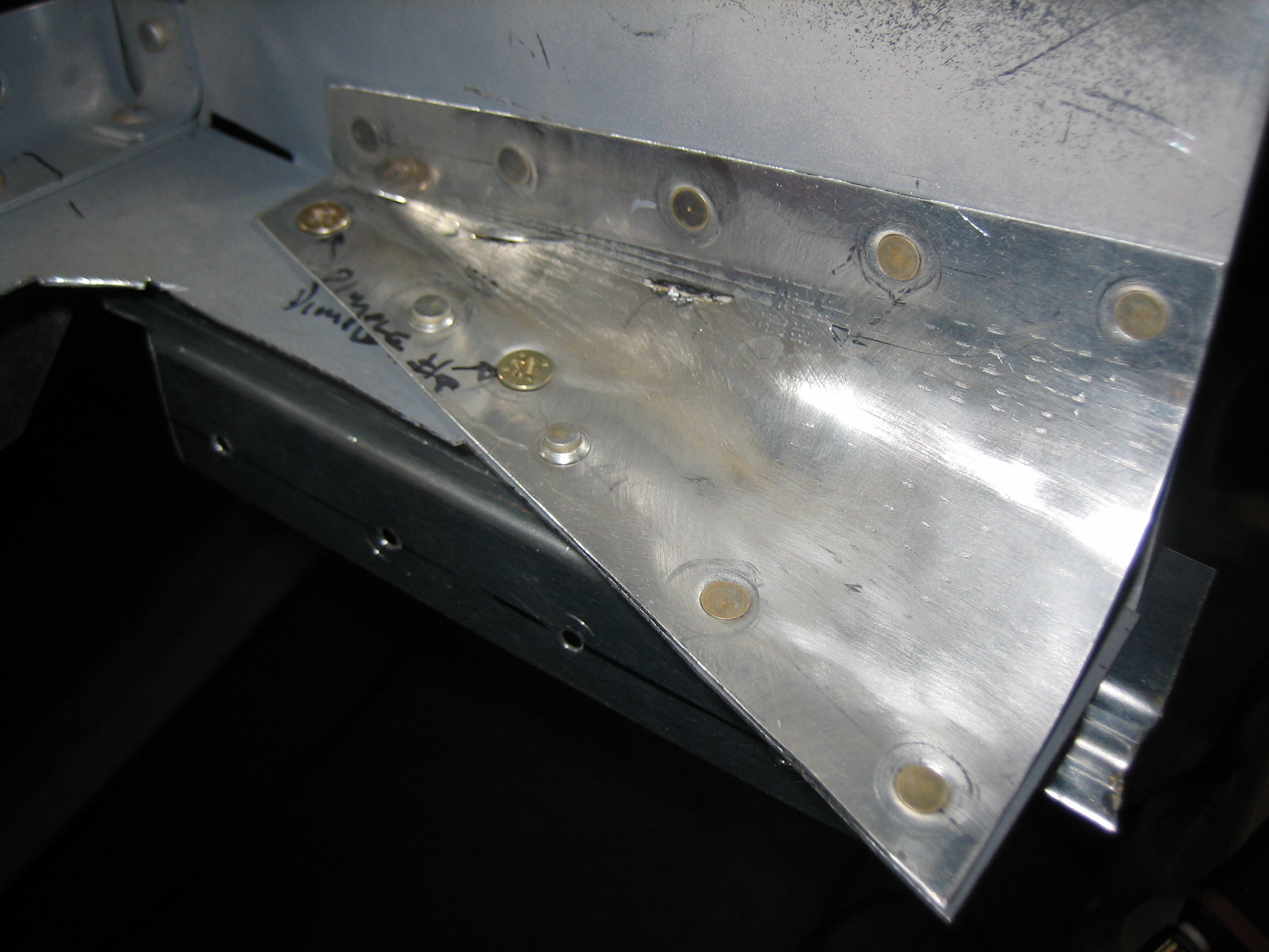
There’s a third screw at the forward end of the flange, but this screw installs from the bottom because of the conical gusset.  The nutplates are K1100-08 for the flush head screws.

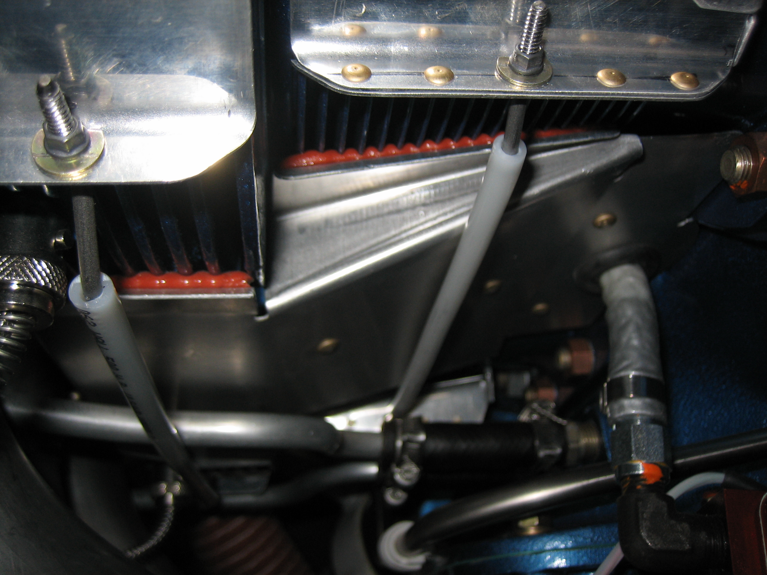
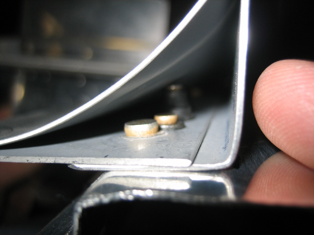
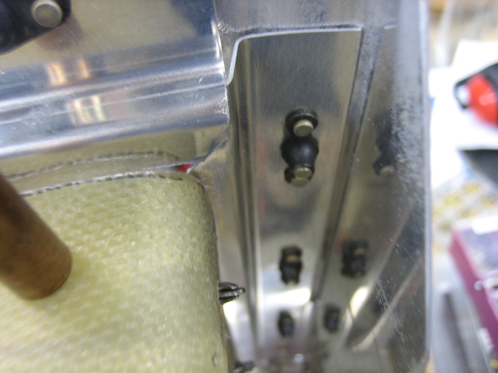
You can see that this screw goes into a K1000-08 nutplate that I mounted under the conical gusset.  I used an AN509-8R6 screw because of the tight clearance.

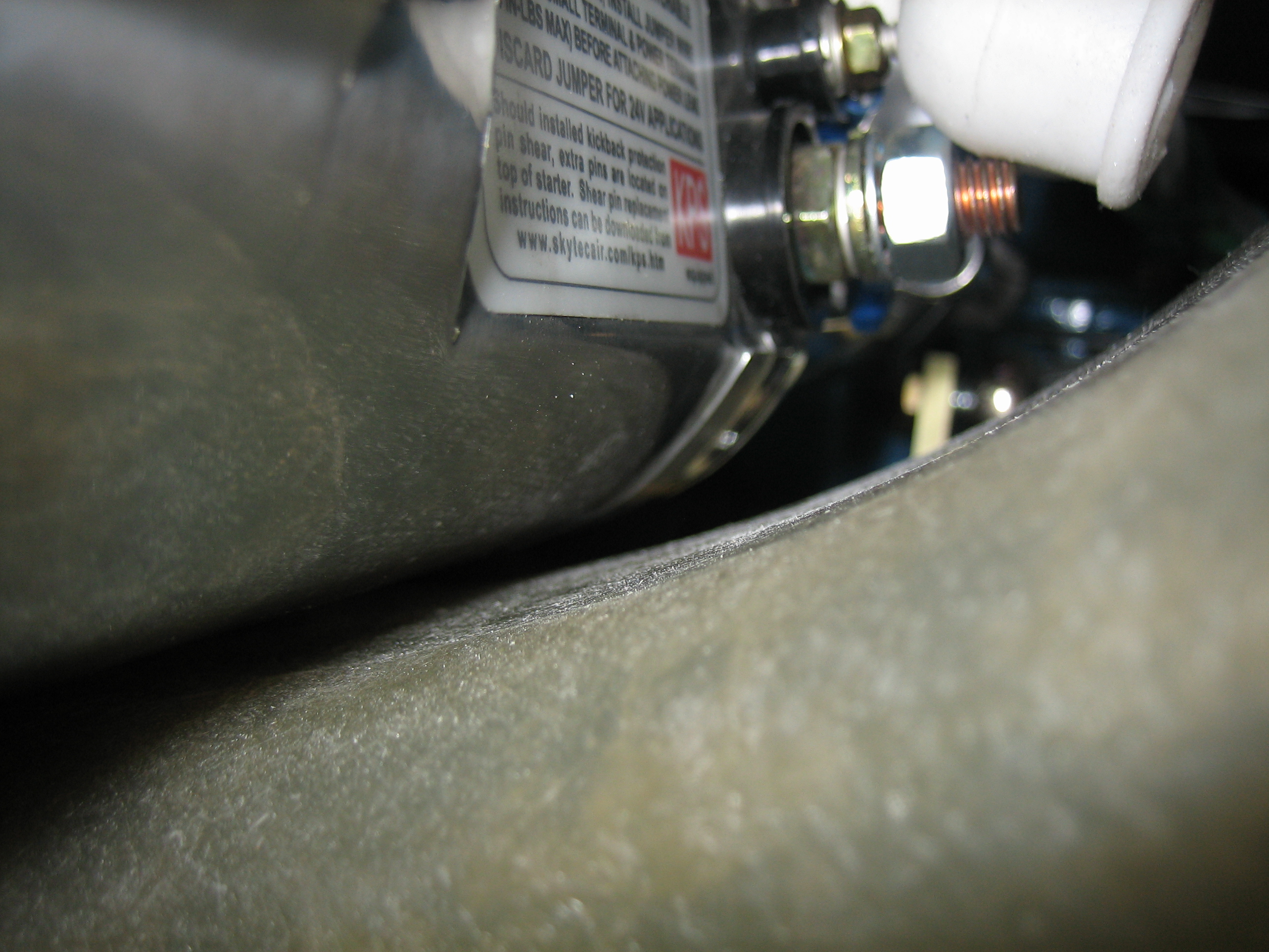
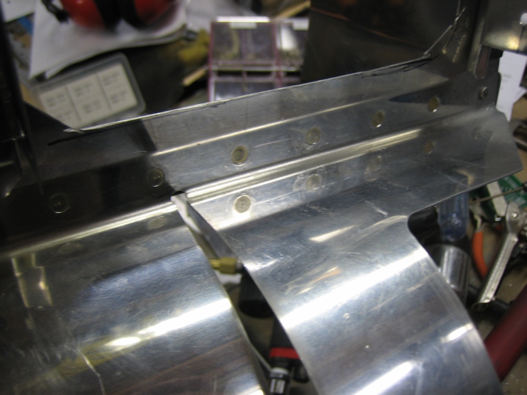
The other flange just has some more AN515-8R8 screws.  I’ll add a third screw at the forward end after I figure out how I’m going to deal with the bracket in the lower left.

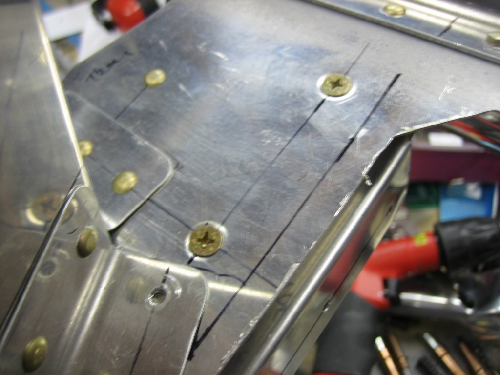
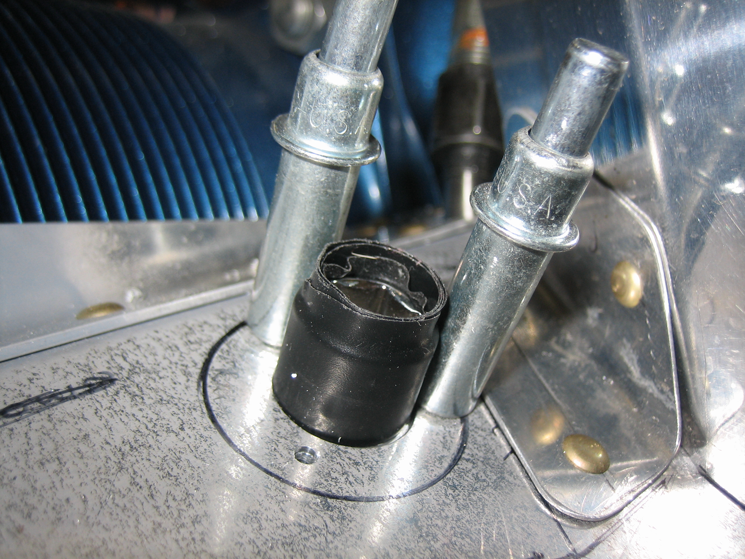
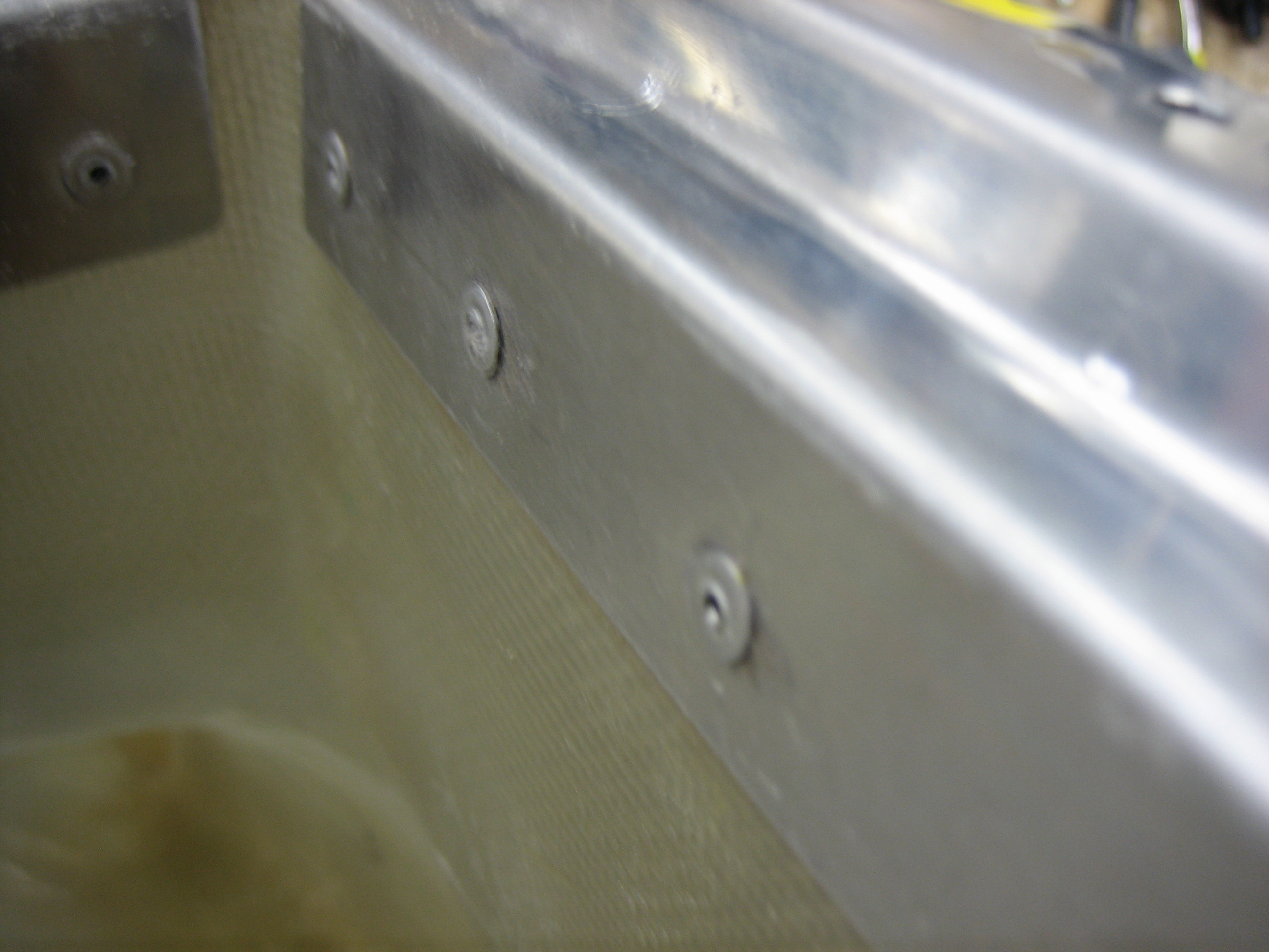
I also replaced 6 of the rivets along the aft edge with ones that are flush along the bottom side since the aft snorkel mounting flange sits against this surface.

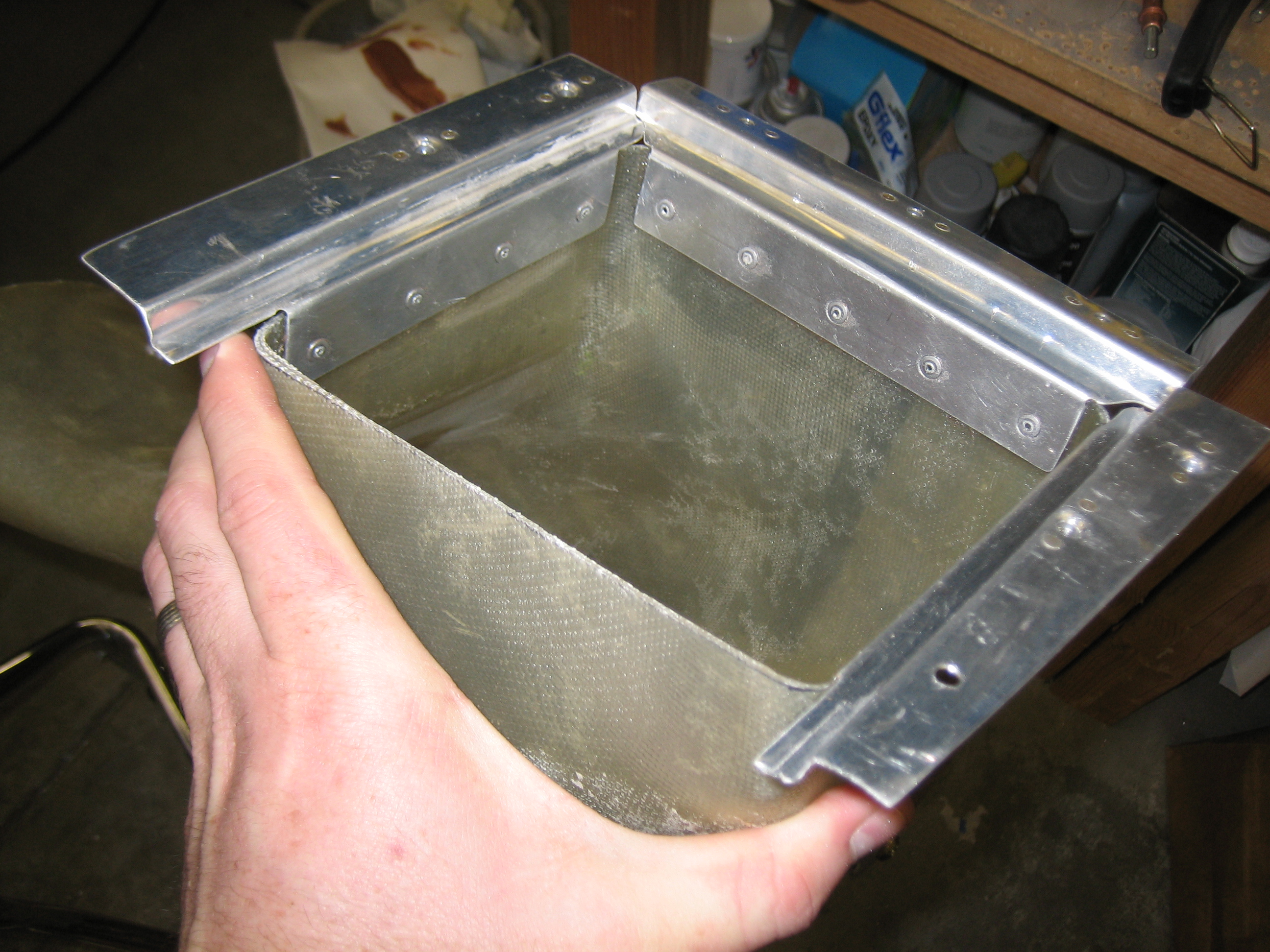
I then drilled three additional holes for AN509-8R8 screws that attach the aft snorkel mounting flange.

I also installed some K1000-08 nutplates along this flange.

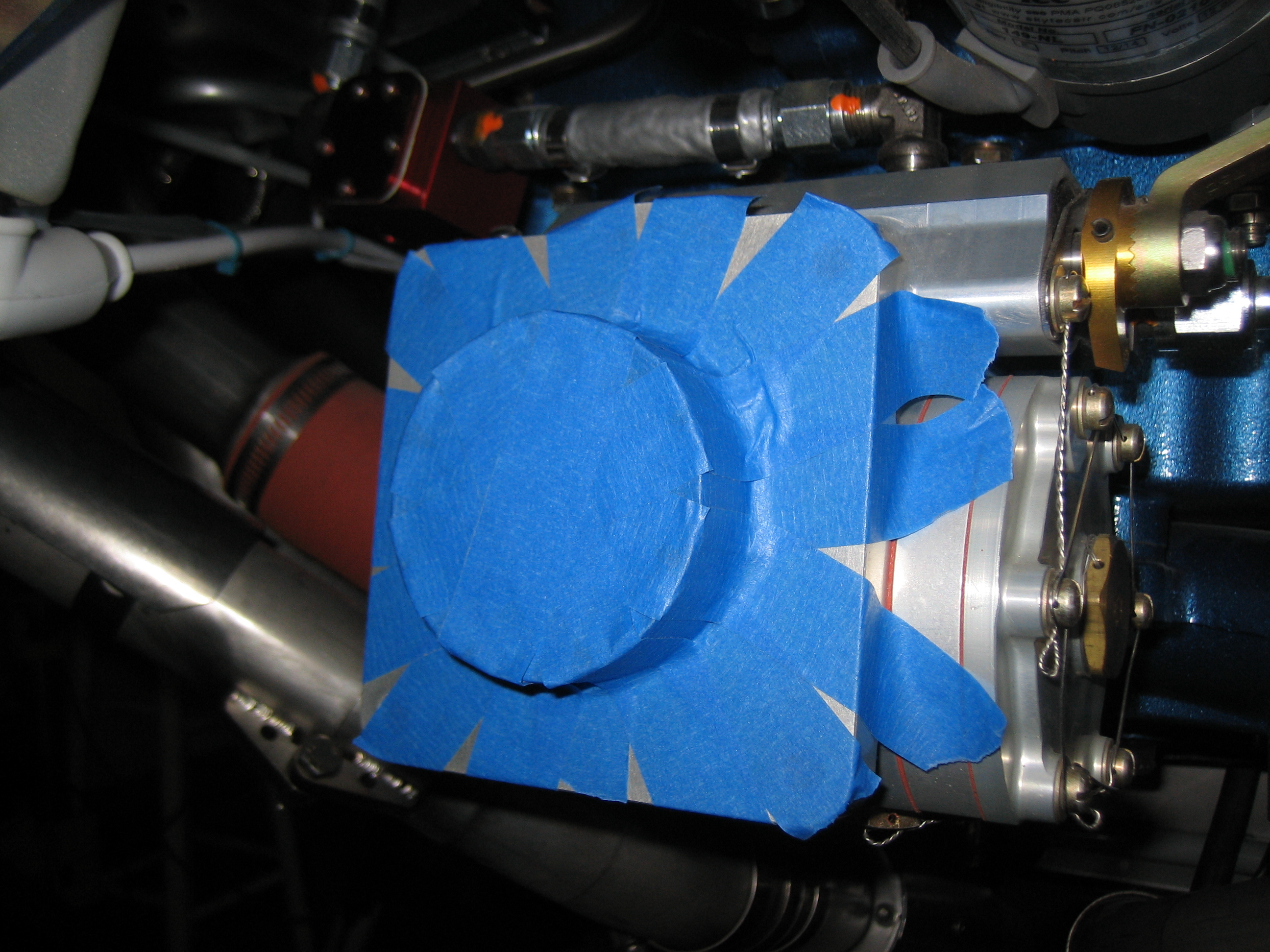
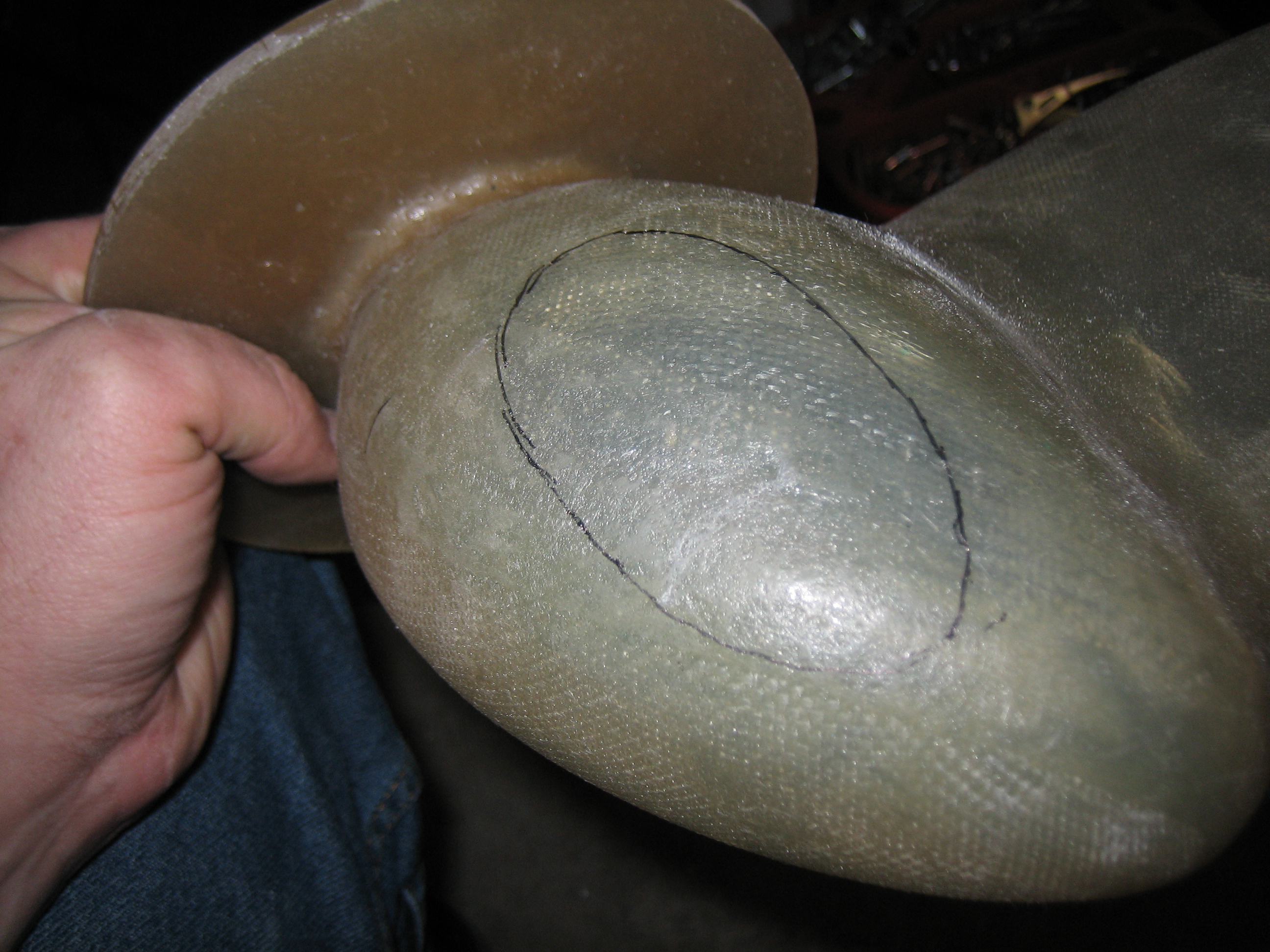
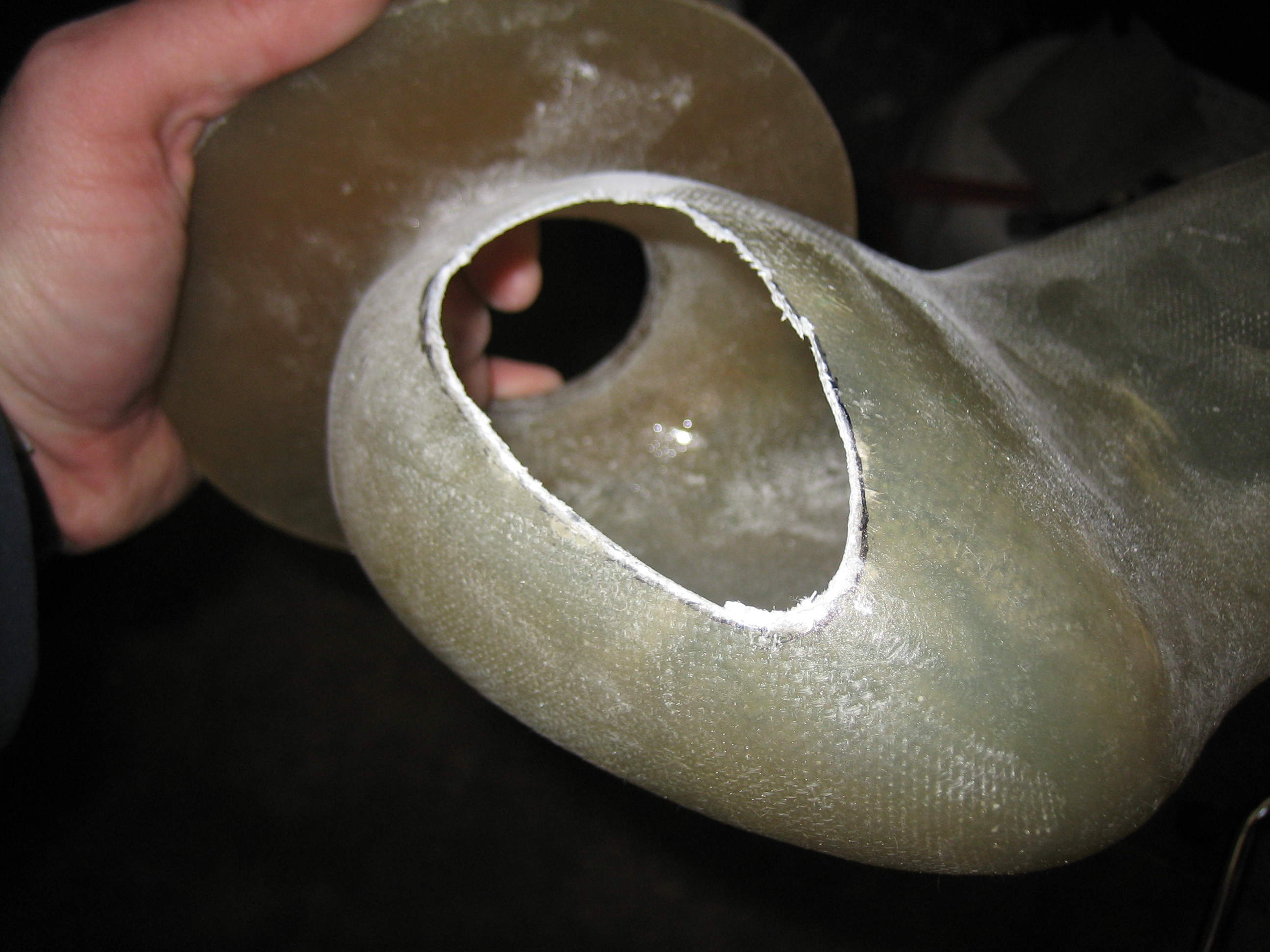
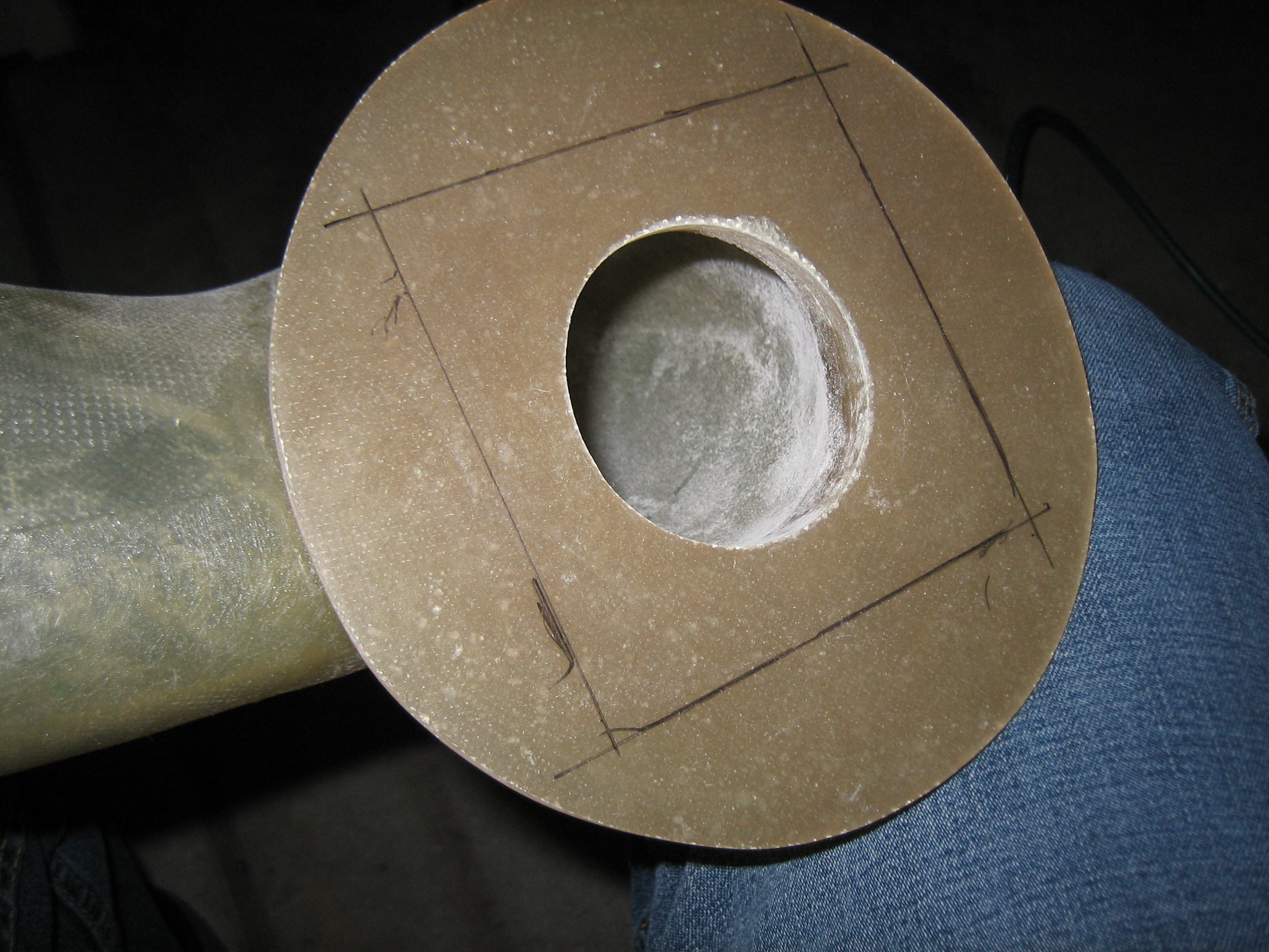
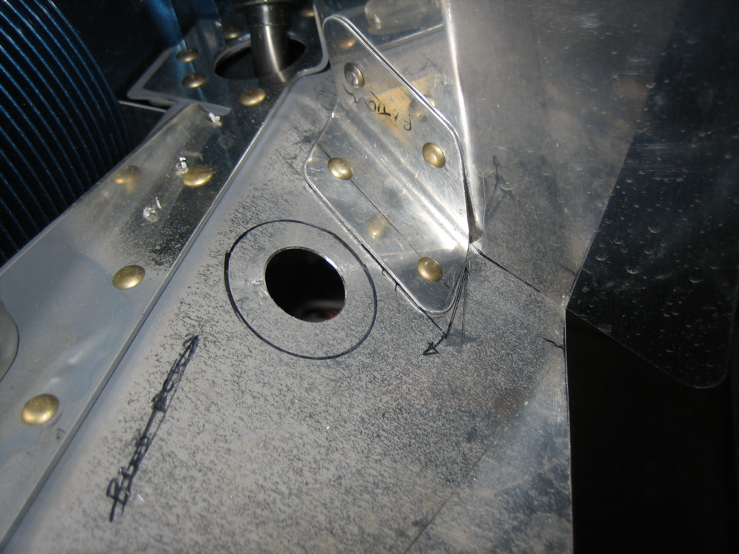
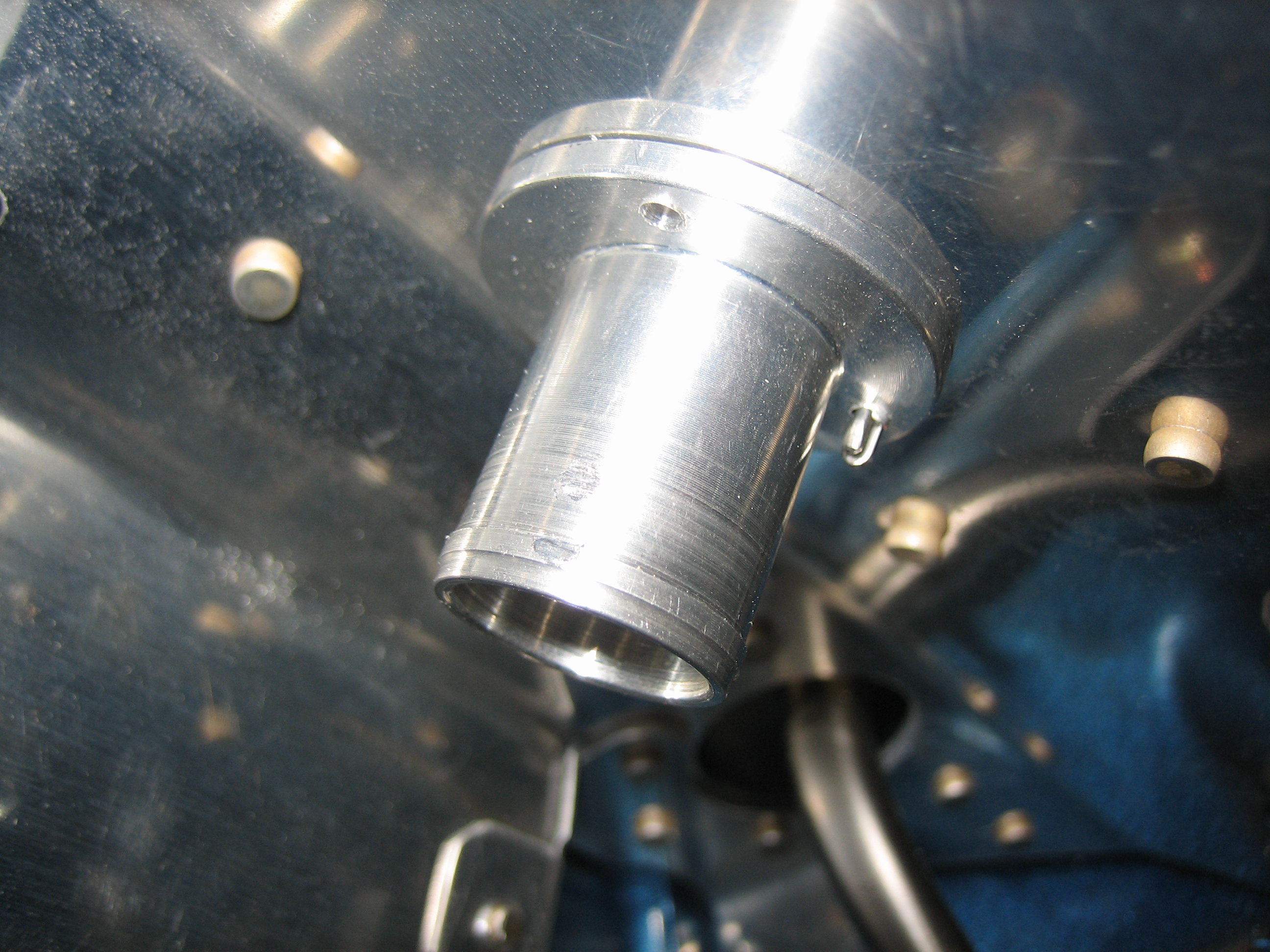
Next up, I drill a 2 5/8″ hole in the side of the snorkel for the alternate air entry.

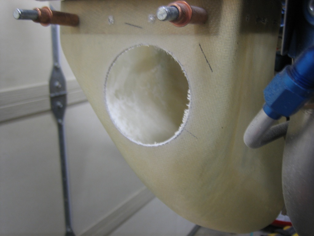
This flange will be mounted here and a pivoting cover will seal the opening under normal circumstances.  If the air filter were to become clogged, I could open this door from the cockpit.

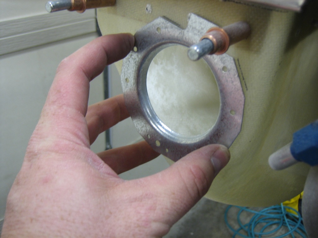
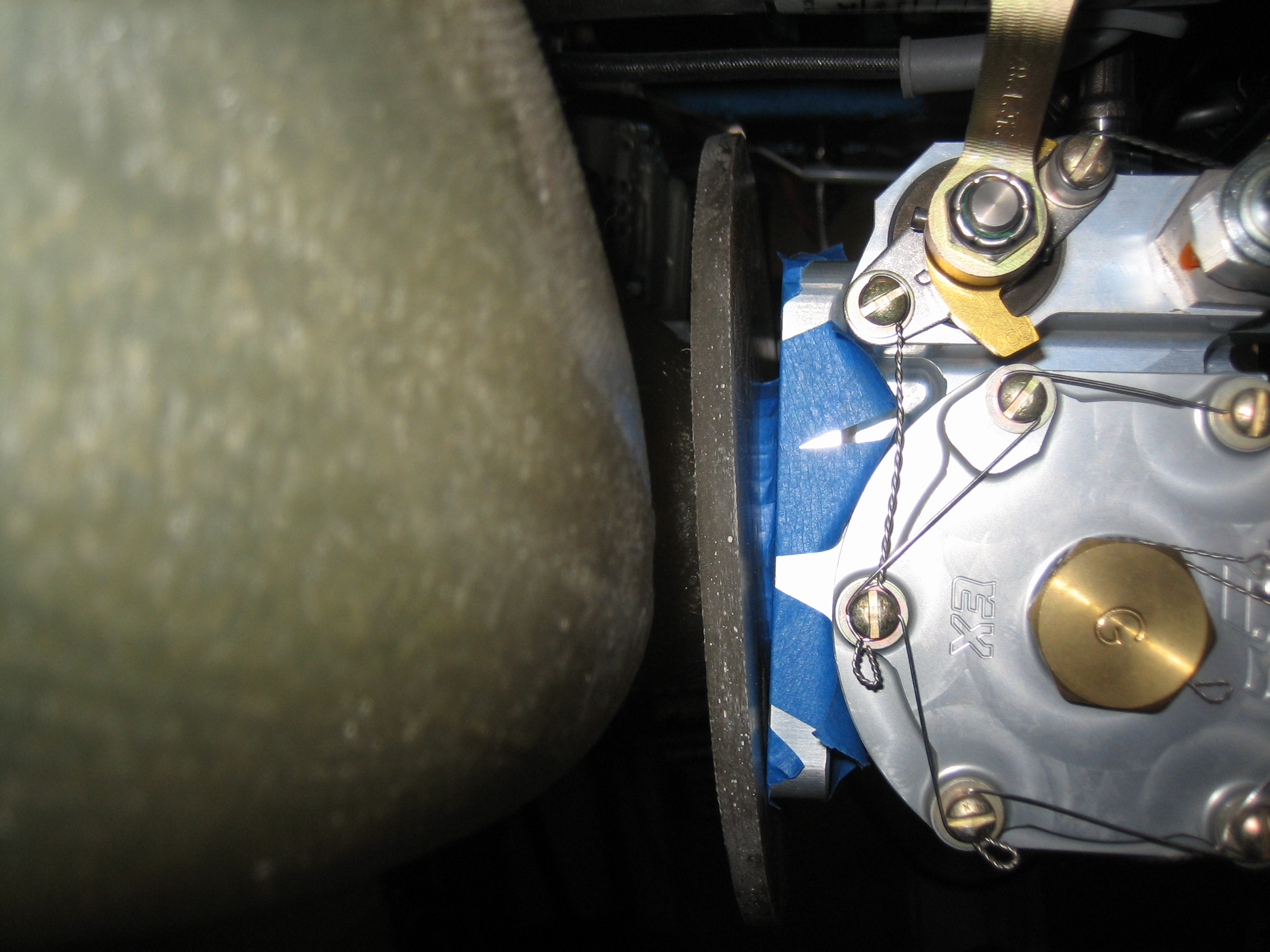
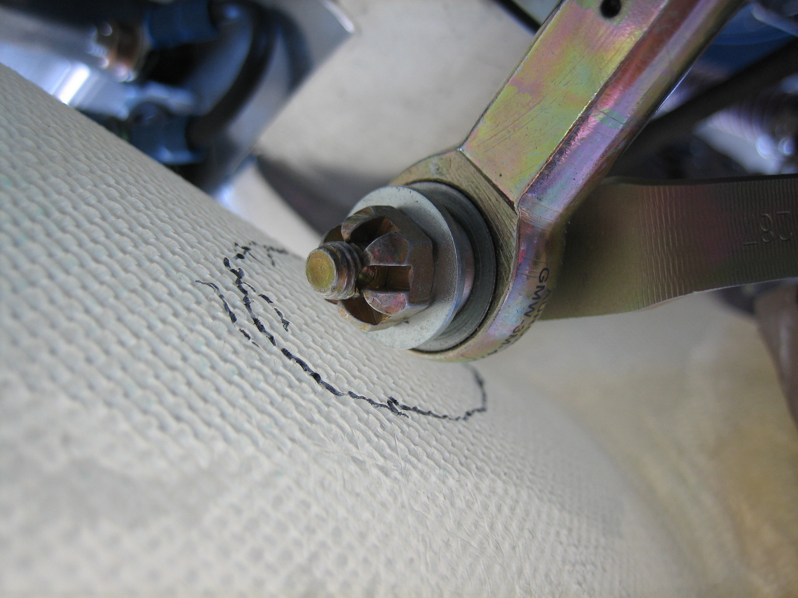
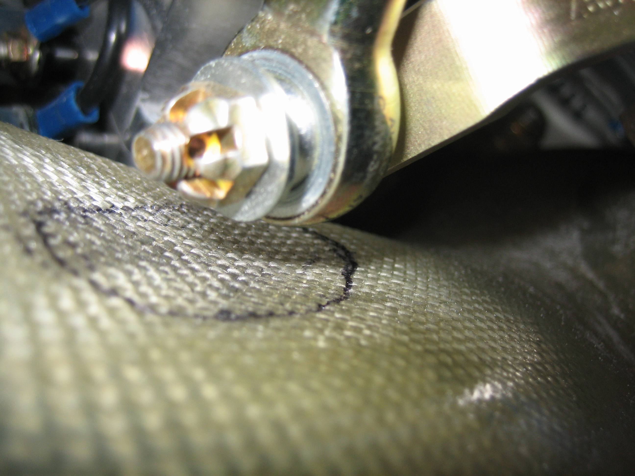
The flange is drilled to the snorkel.  The center hole in the bottom of the flange needs to be match drilled to the snorkel using a #19 drill and then later opened up to 1/4″ in the snorkel so that the nutplate can fit through the hole.

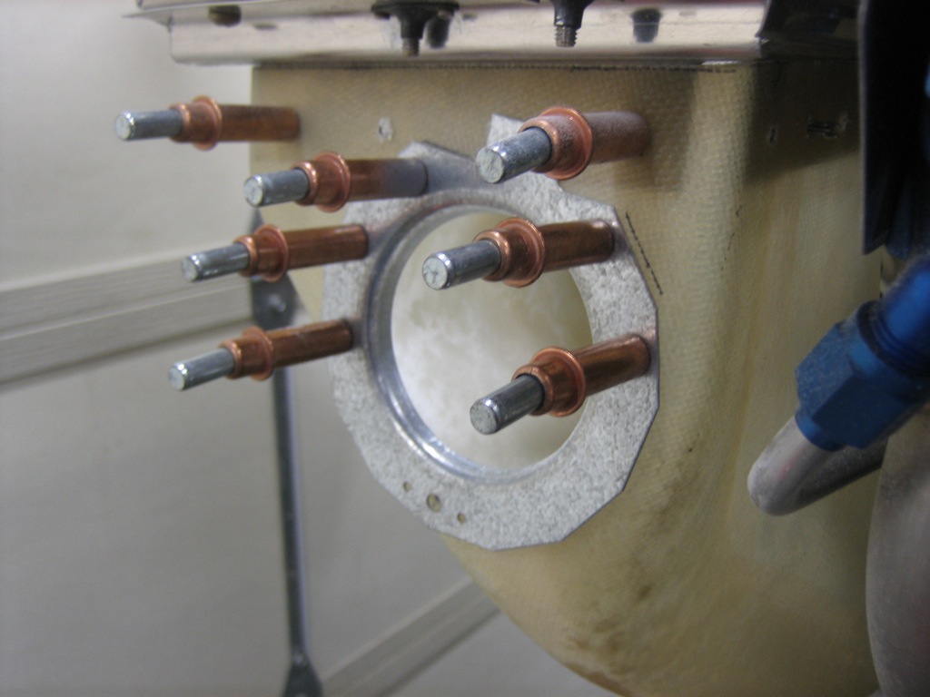
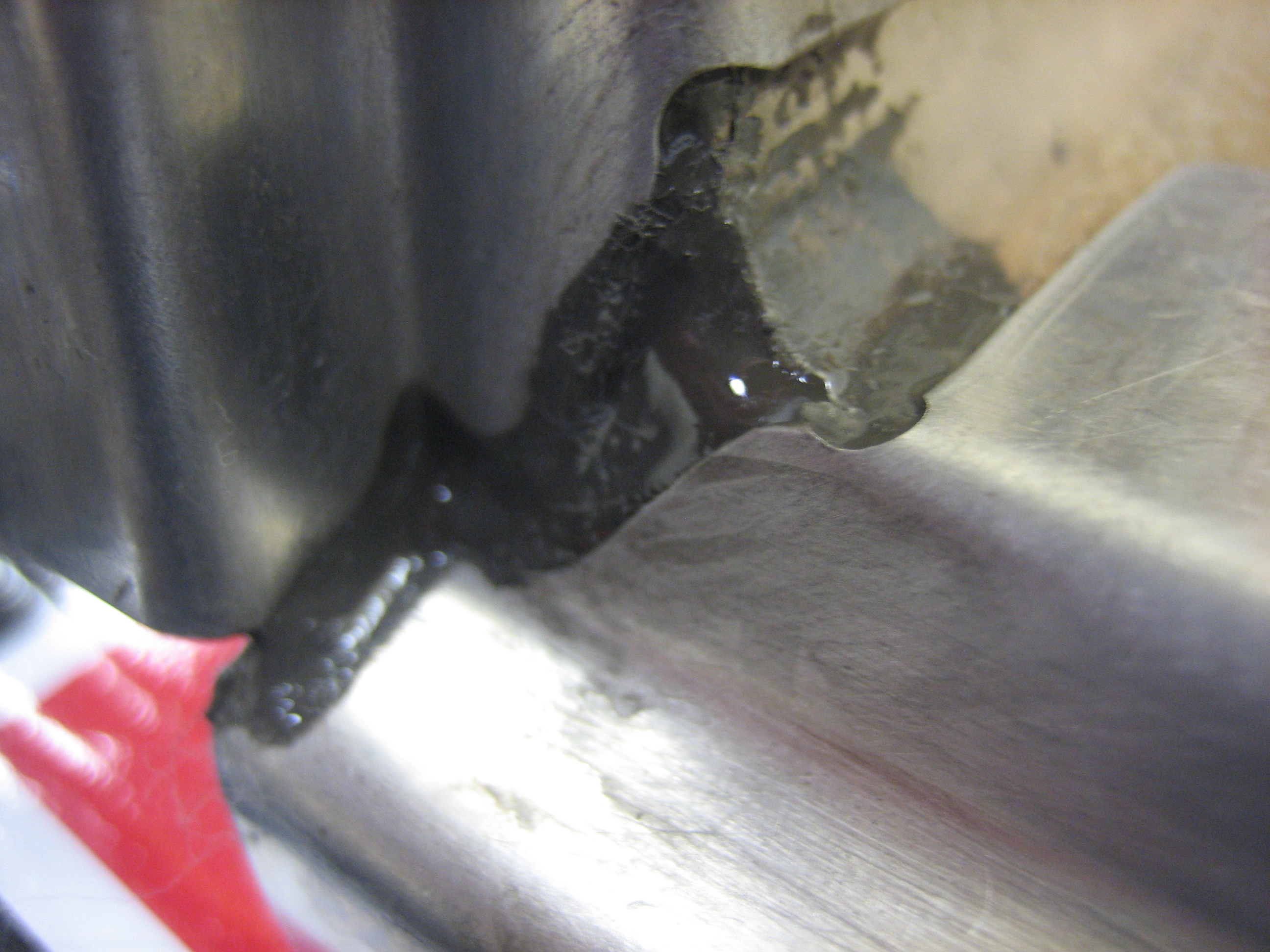
Finally, I sanded and cleaned the surface and flange, then clecoed it down with some epoxy mixed with flox.  I then roughly faired in the flange so that there is a nice transition to the snorkel.  The flox leaves a fairly rough surface though; I’ll use some filler to smooth this out nicely after it cures.

Worked on Snorkel

I’ve been traveling for work recently, so I haven’t had much time to work on the plane.  I did manage to put a couple of hours in on the project today though,  First up, the mixture control cable interferes with the snorkel in the full lean position.  I marked the snorkel and will have to glass in a blister.

Next up, I mixed up some epoxy with flox and riveted the upper flanges on to the snorkel.

The rivets are flush on the inside (mostly) so that they don’t interfere with the air filter.

On the outside, small washers were slipped over the rivet shanks before pulling to spread the load out on the glass.

Finally, I mixed up some proseal and sealed the corners between the flanges to prevent air leaks around the filter.

Finished Glassing Snorkel

Instead of cutting and glassing in a dimple to clear the mixture arm, I heated the snorkel with a heat gun and simply pressed in with my thumb to create a depression.  There’s just over 1/8″ of clearance now, but the mixture arm is only in this position when the mixture is in idle cutoff.  When the engine is running, the arm is no where near the snorkel.

I also opened up the hole for the alternator clearance a bit and then prepped four layers of 9oz bid cloth between a couple of sheets of plastic (this picture was obviously taken after I cut out the piece to be applied to the snorkel).

Here’s the glass applied to the snorkel.

I was having a hard time keeping the edges of the glass stuck down to the snorkel because of the tight curve, so I laid a piece of plastic over it and taped it tight.  I also wanted to keep the center depressed to provide additional clearance for the alternator bracket, so I taped a paper towel down over the depression.  I should have roughly 1/4″ of clearance between the snorkel and the alternator bracket.

Started Filling Snorkel

I mixed up some West System epoxy and lightweight filler and smeared a coat over the snorkel.  This will fill the weave and smooth out the transition to the new glass I applied yesterday.  This stuff is pretty easy to sand, so I don’t have to worry too much about getting this really smooth right now.