More Progress Modifying Baffles for ECI Tapered Cylinders

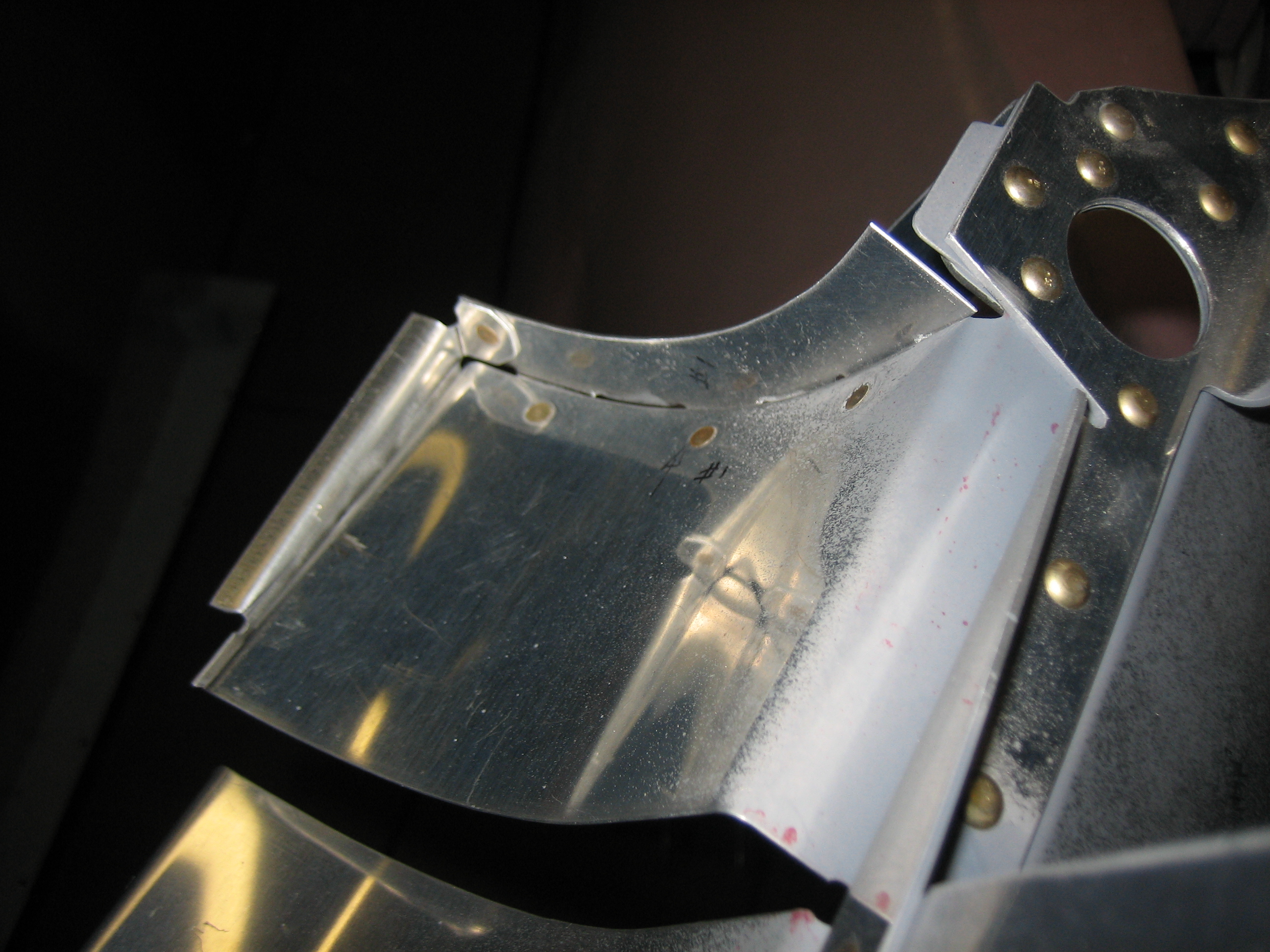
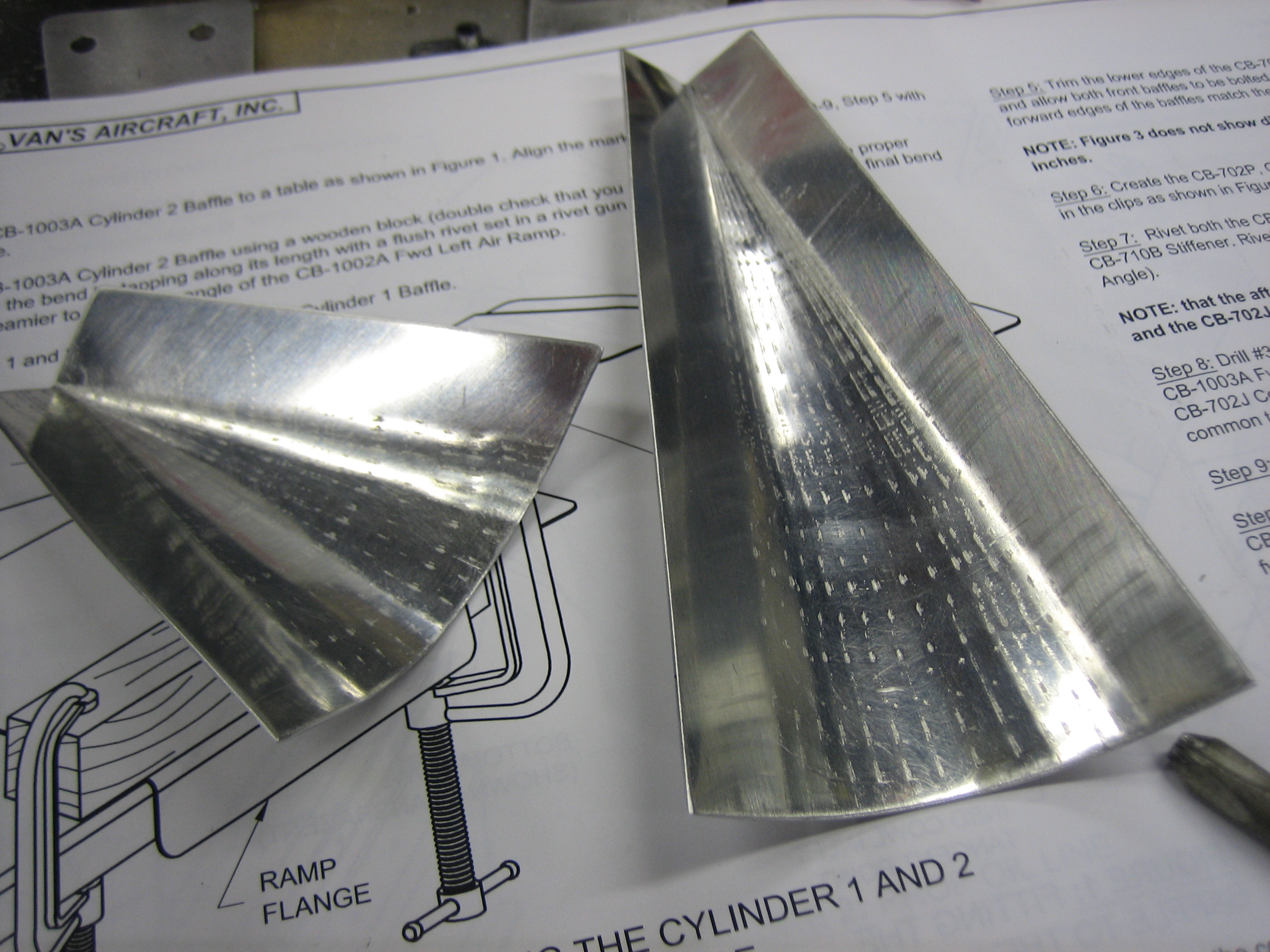
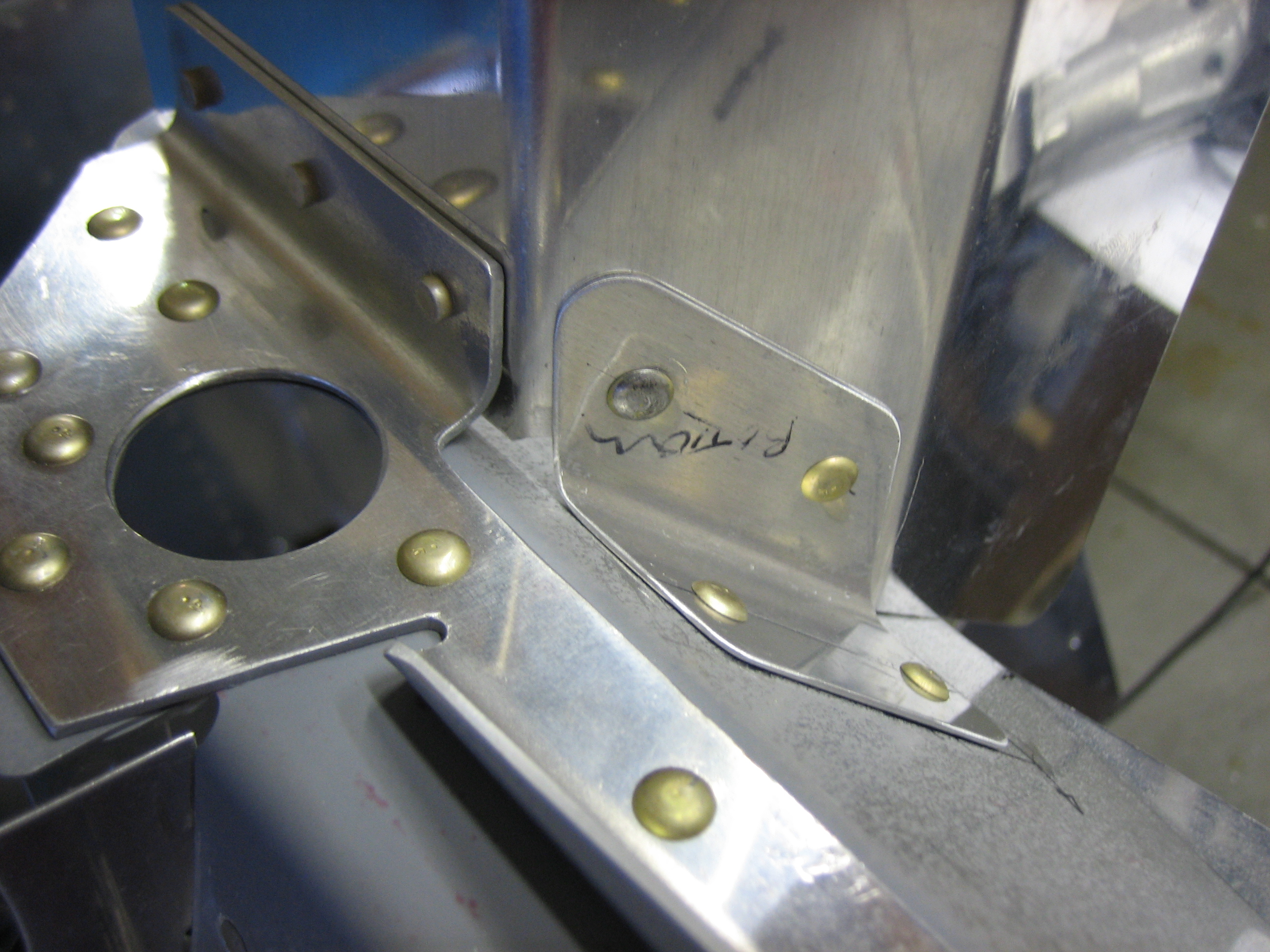
Where the baffles end, a tapered shim needs to be fabricated so that the baffles seal tight against the fins.  This forces all of the cooling air to go between the fins instead of around them.

This shim will be riveted to the flange on the end of the curved portion of the baffles.

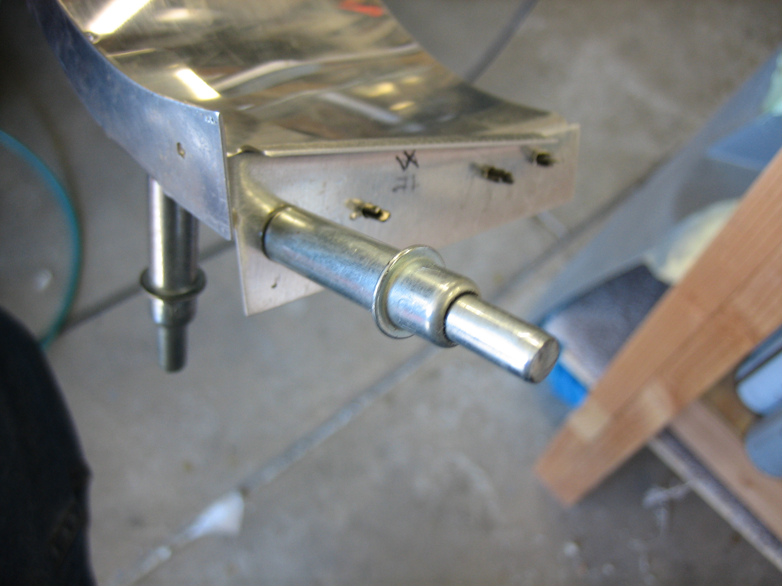
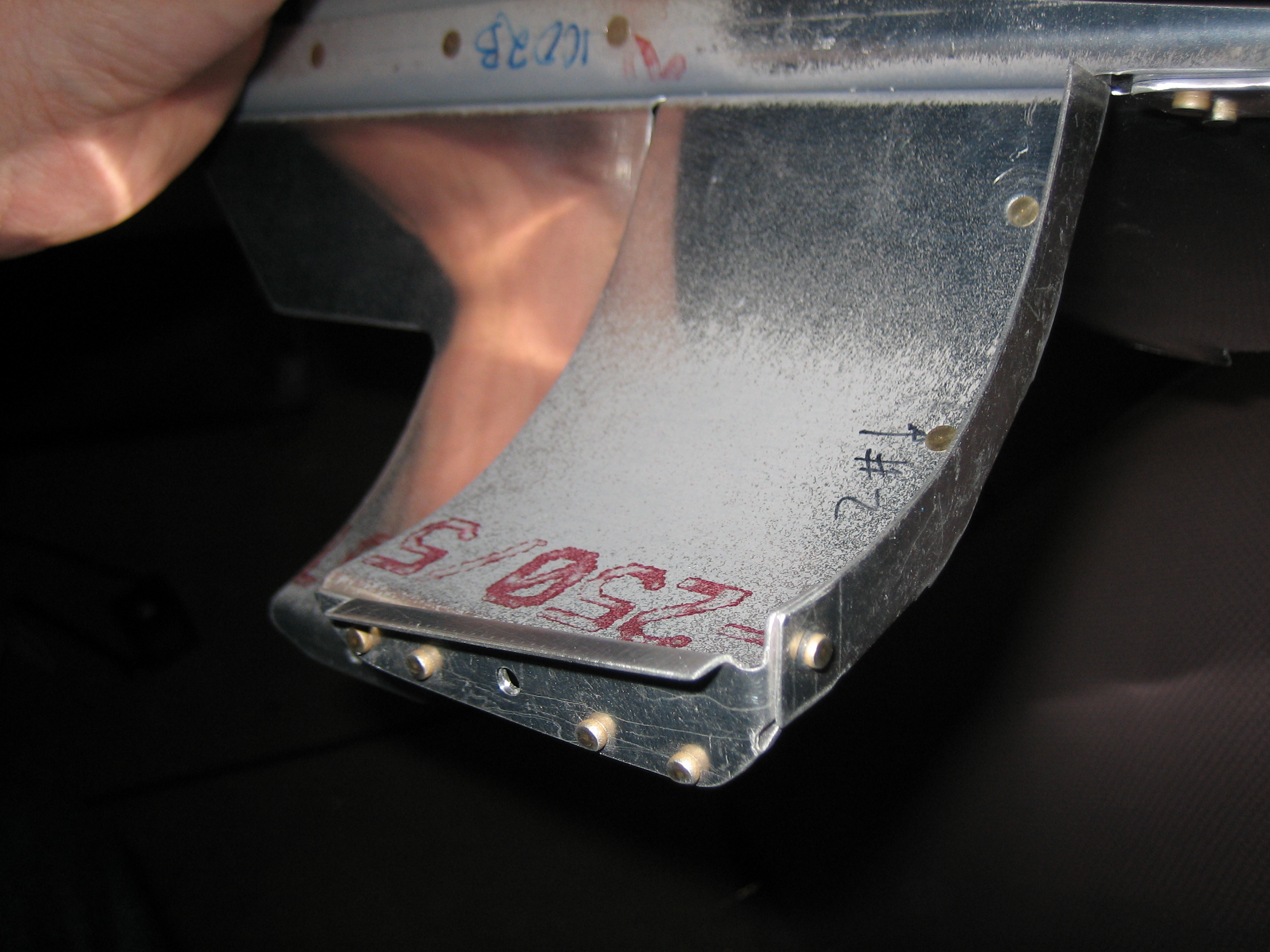
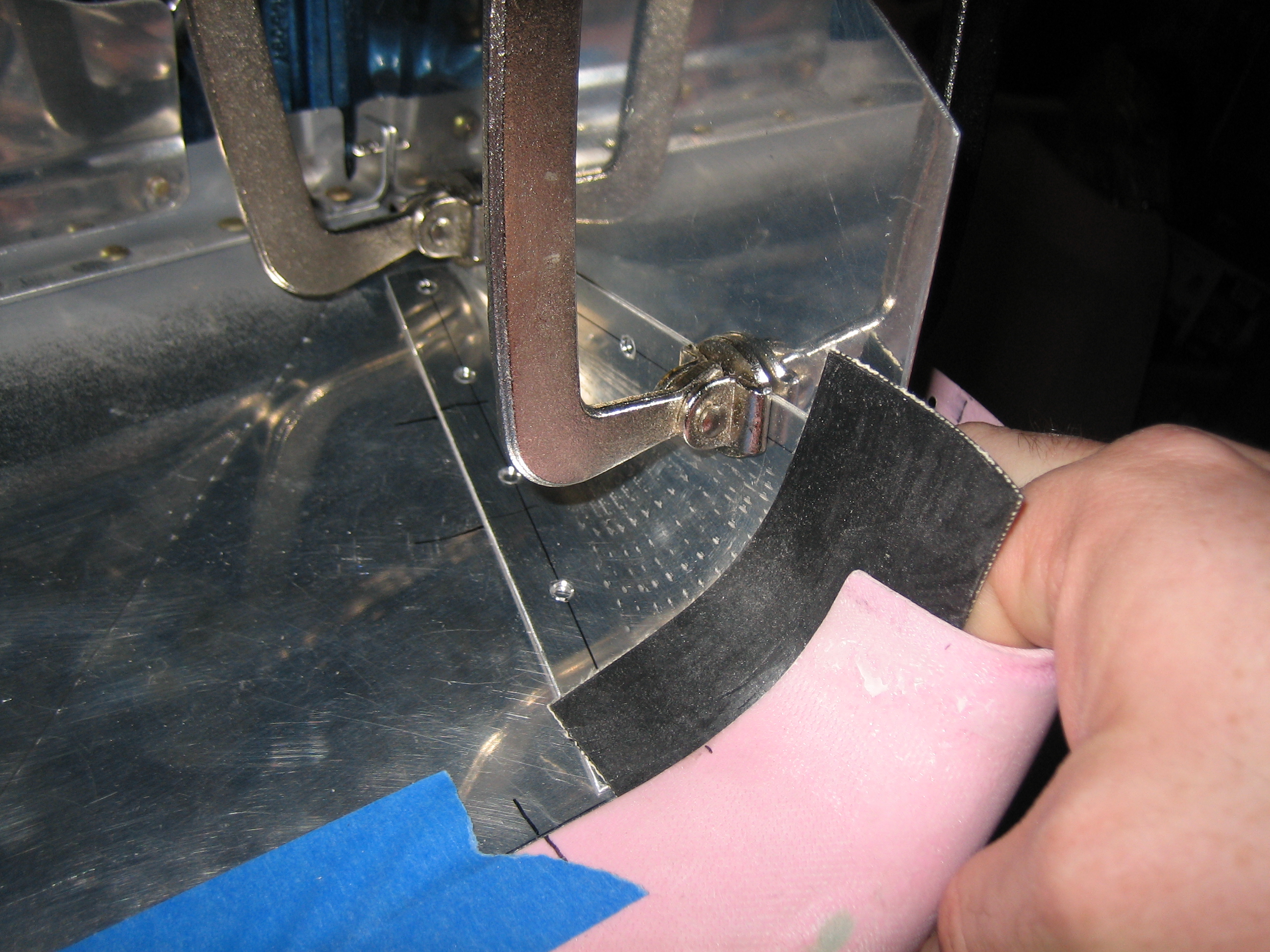
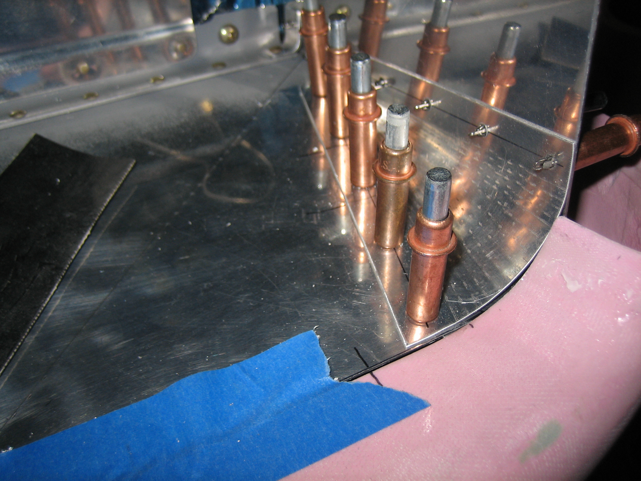
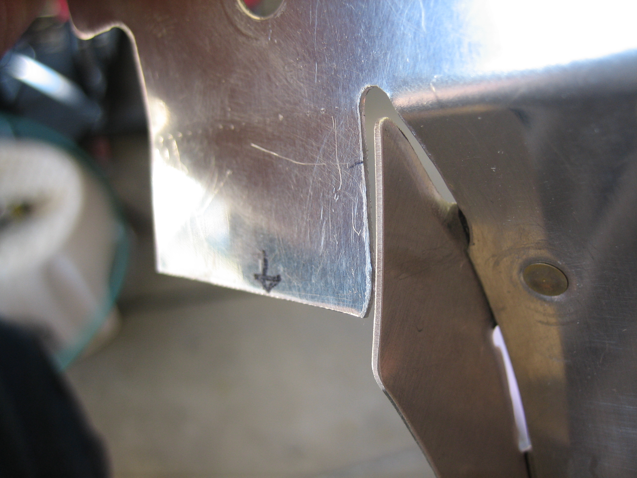
I left the new piece long while fitting it.  I’ll trim it off flush with the existing flange now that the holes are drilled and its position is fixed.

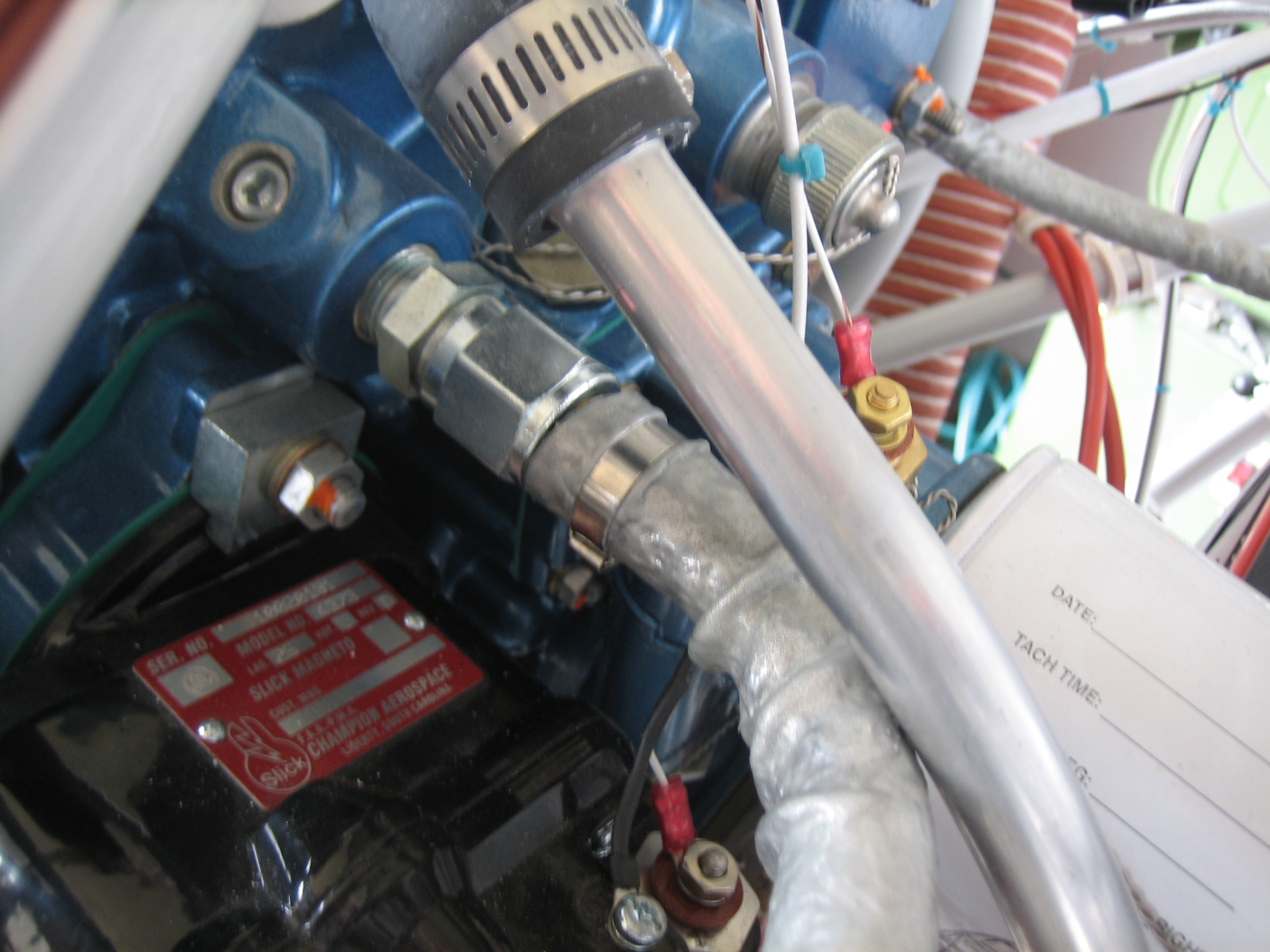
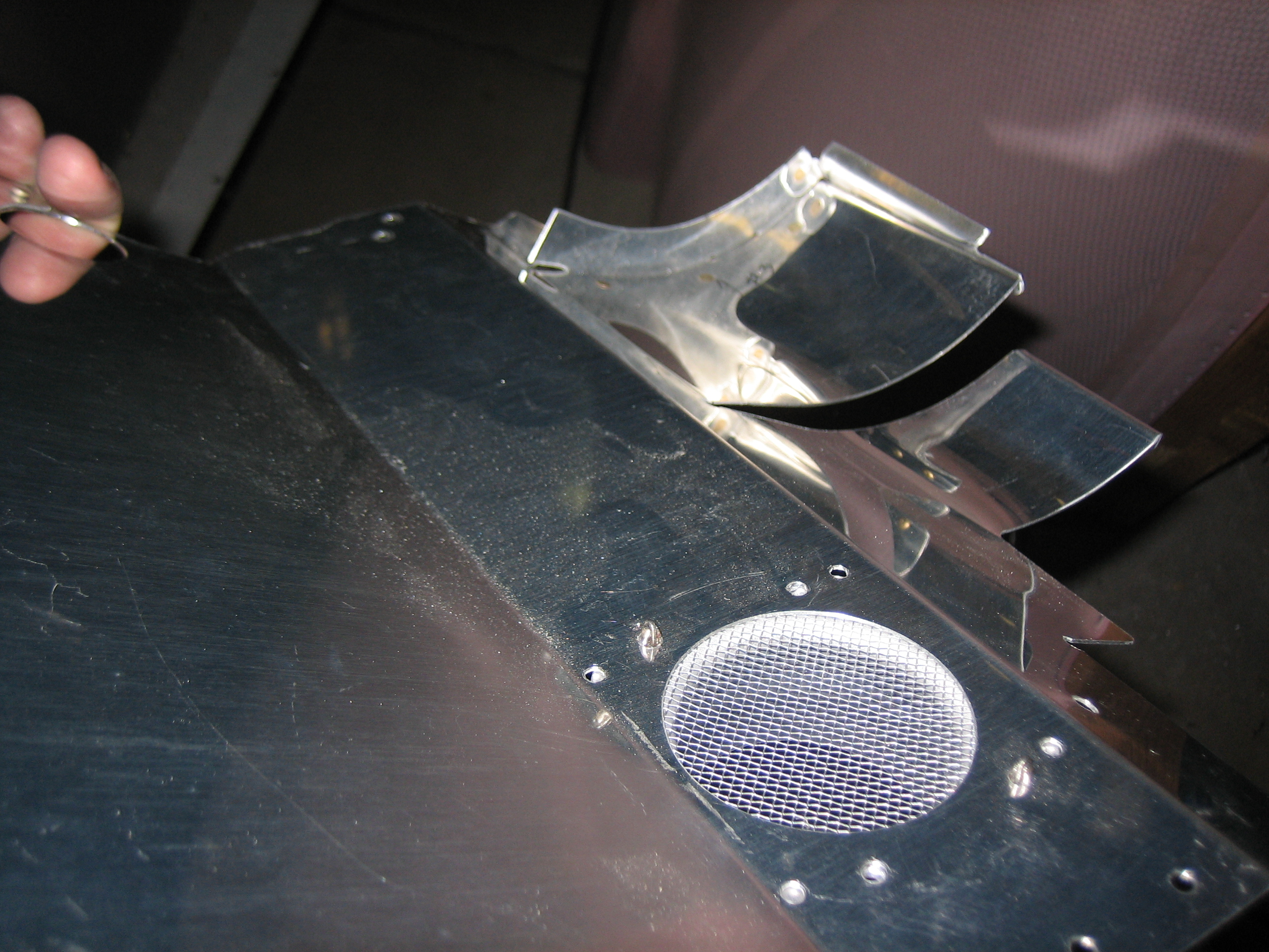
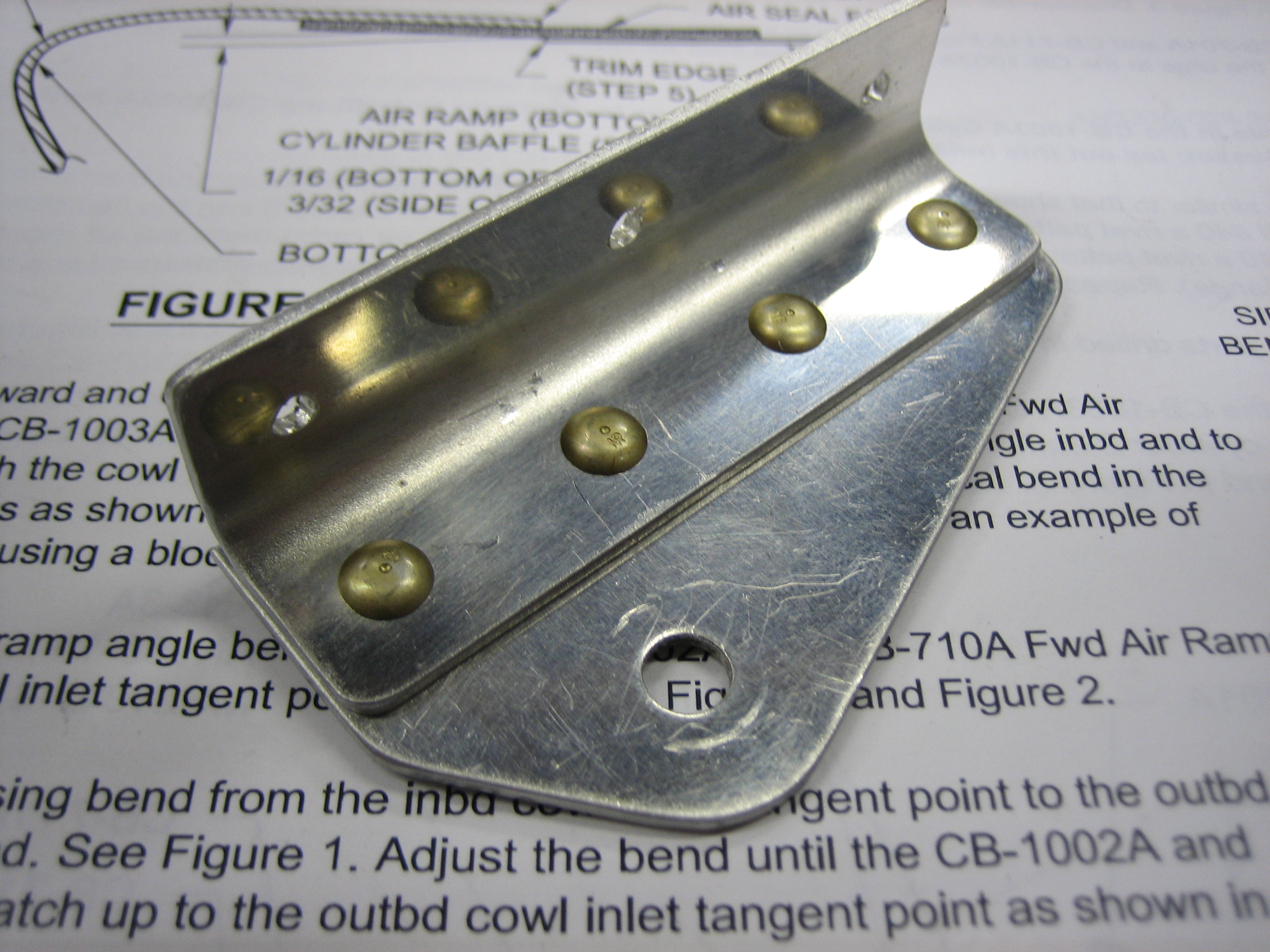
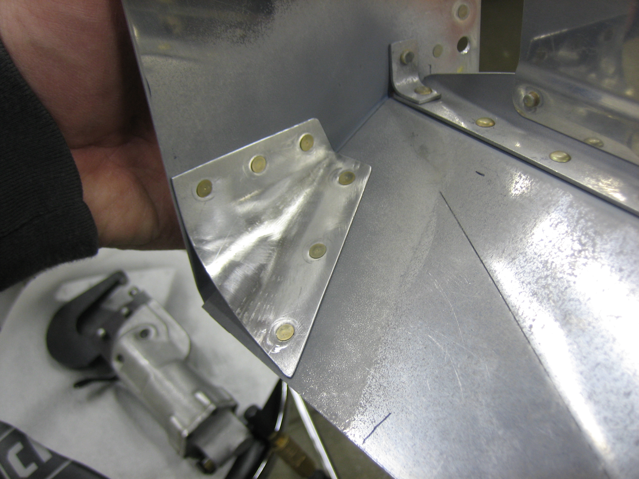
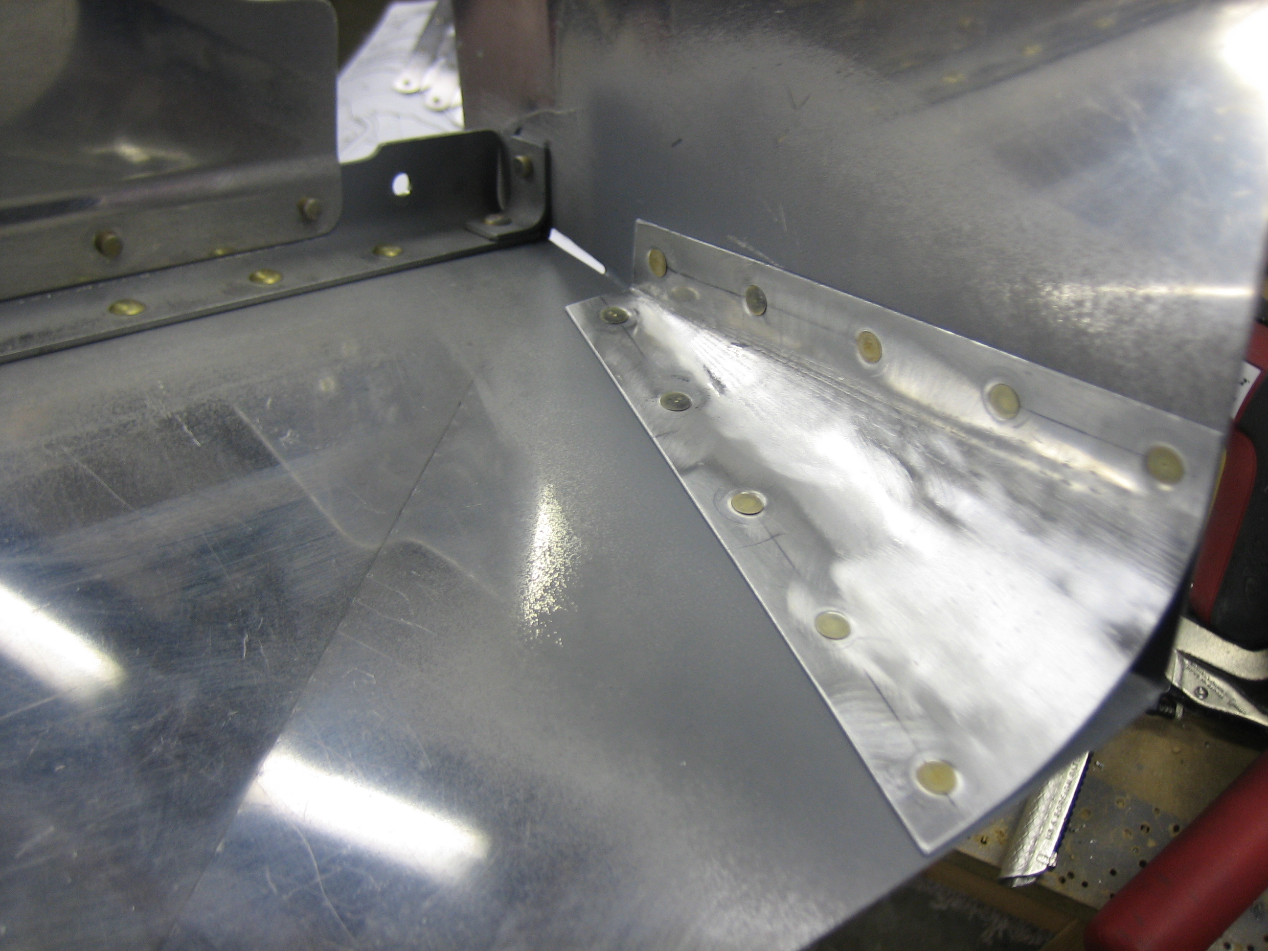
Here’s what it looks like with everything riveted together.

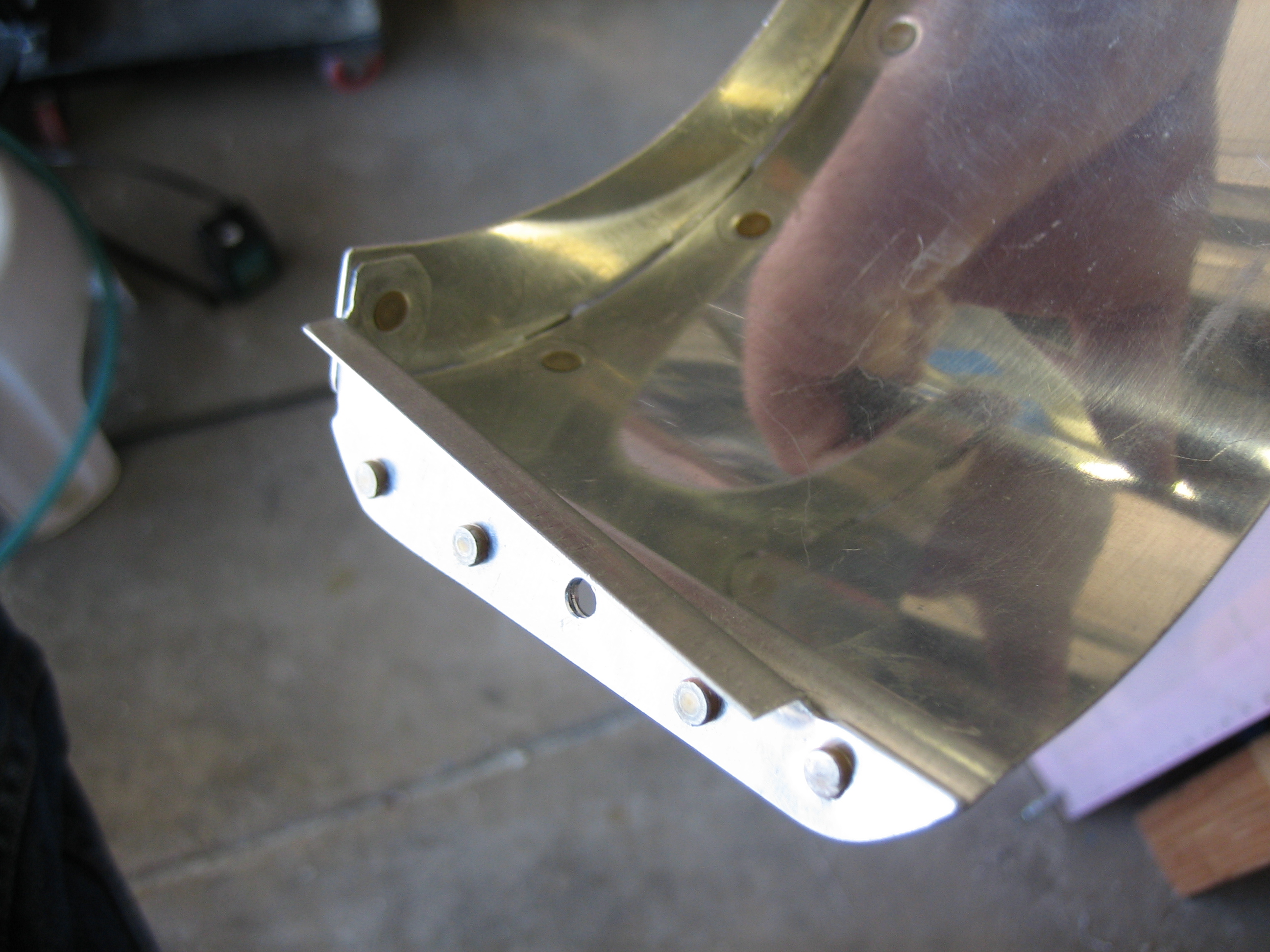
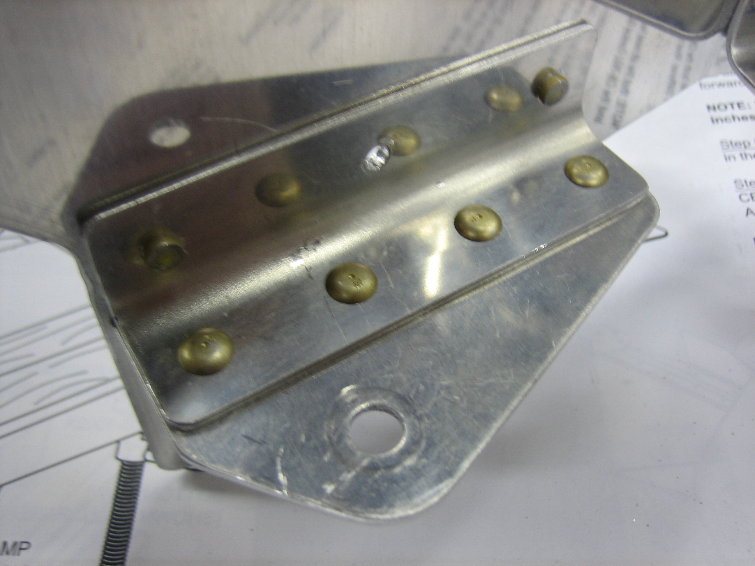
From the other side, you can see the ears of the side piece and the rivet that ties it to the tapered shim.

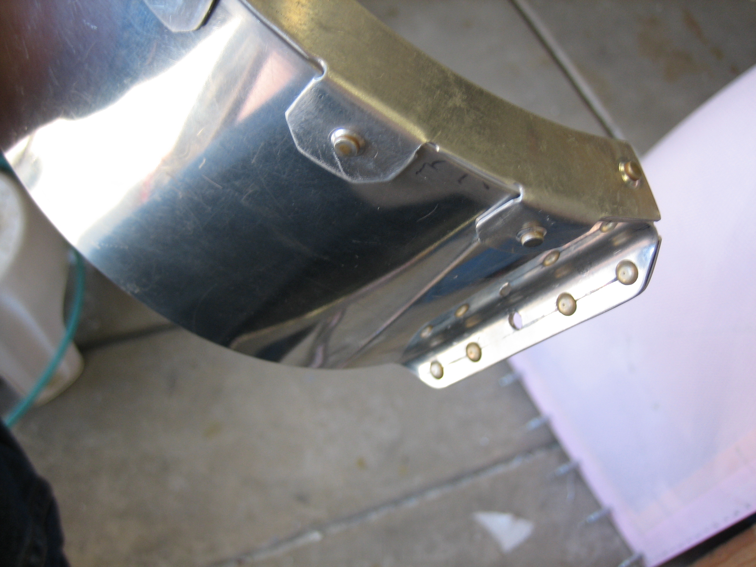
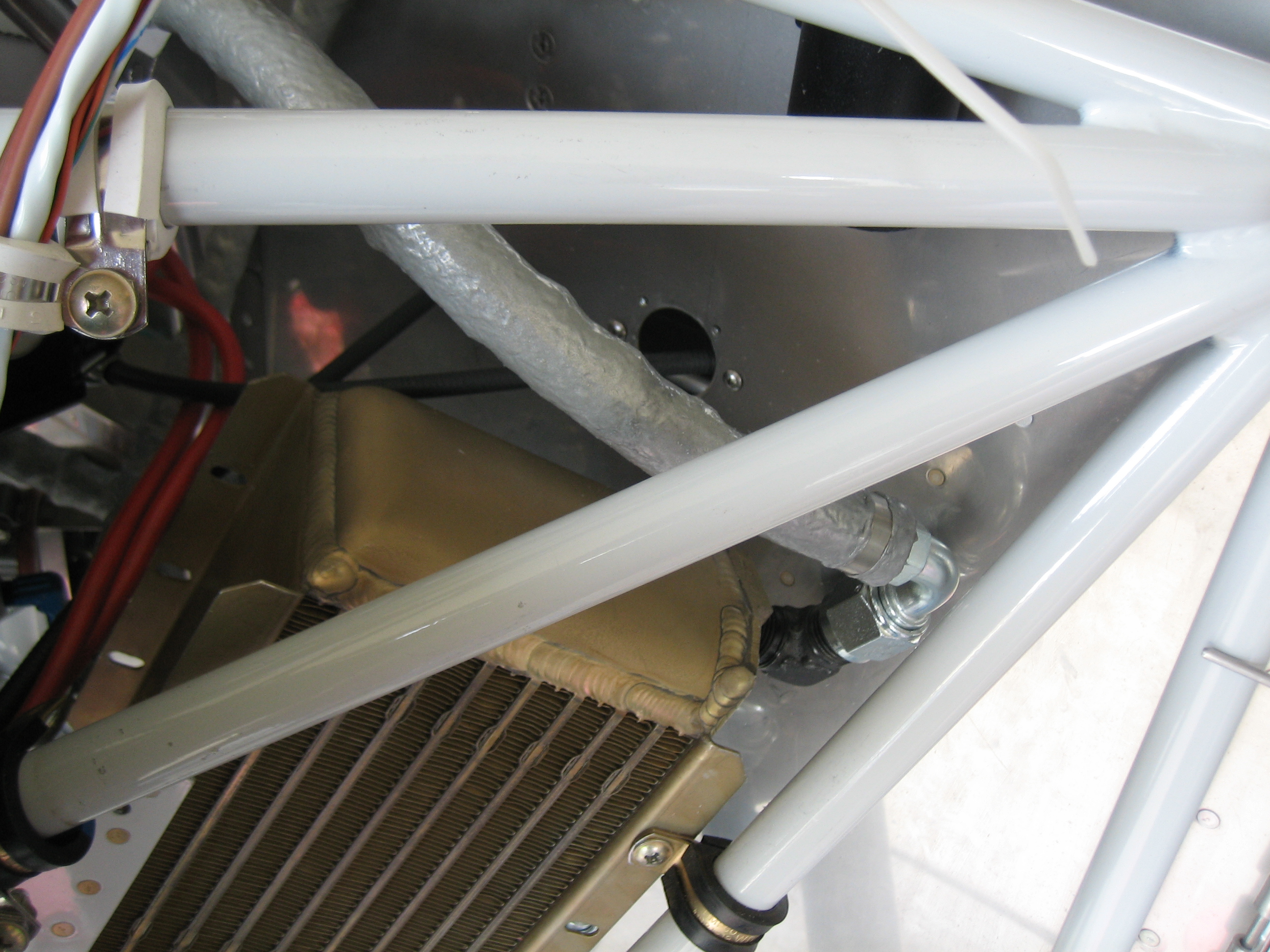
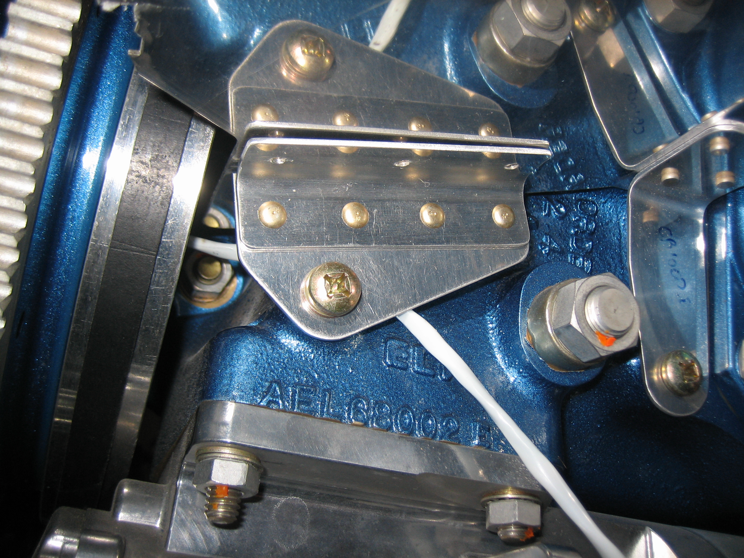
The modifications for cylinders 1-3 are pretty much the same.  The modification for cylinder #4 is quite a bit different.  It wraps much farther around the cylinder and the width of this side piece gets larger near the top.  I trimmed it to roughly follow the ear that rests above one of the cylinder mounting nuts.  All of the gaps will be filled with high-temp RTV silicone.

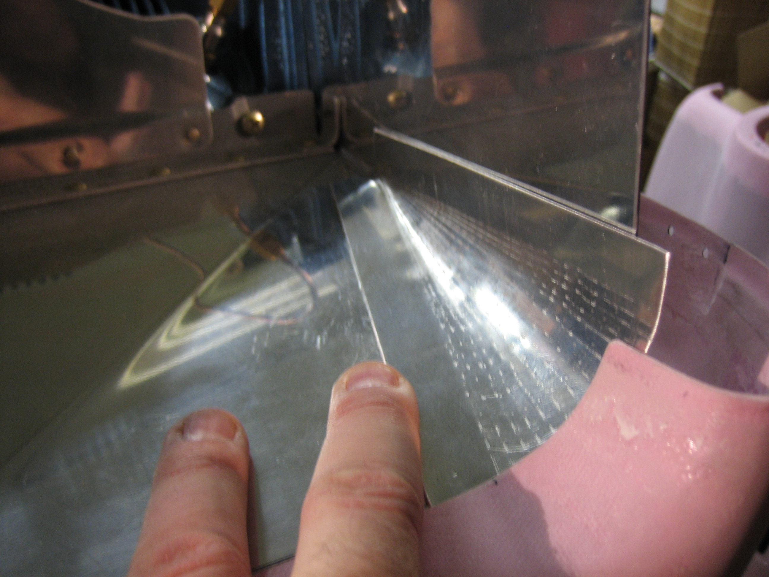
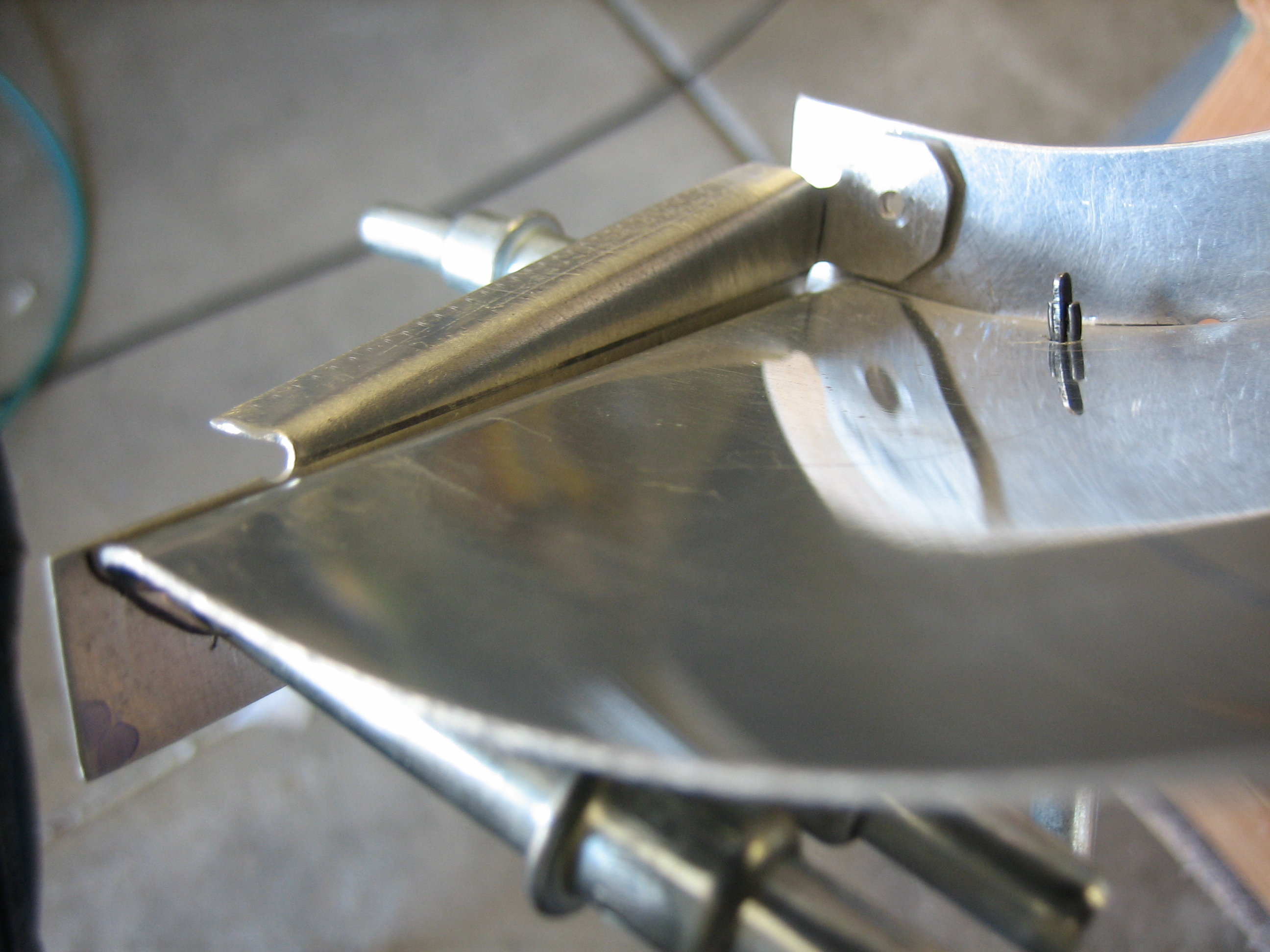
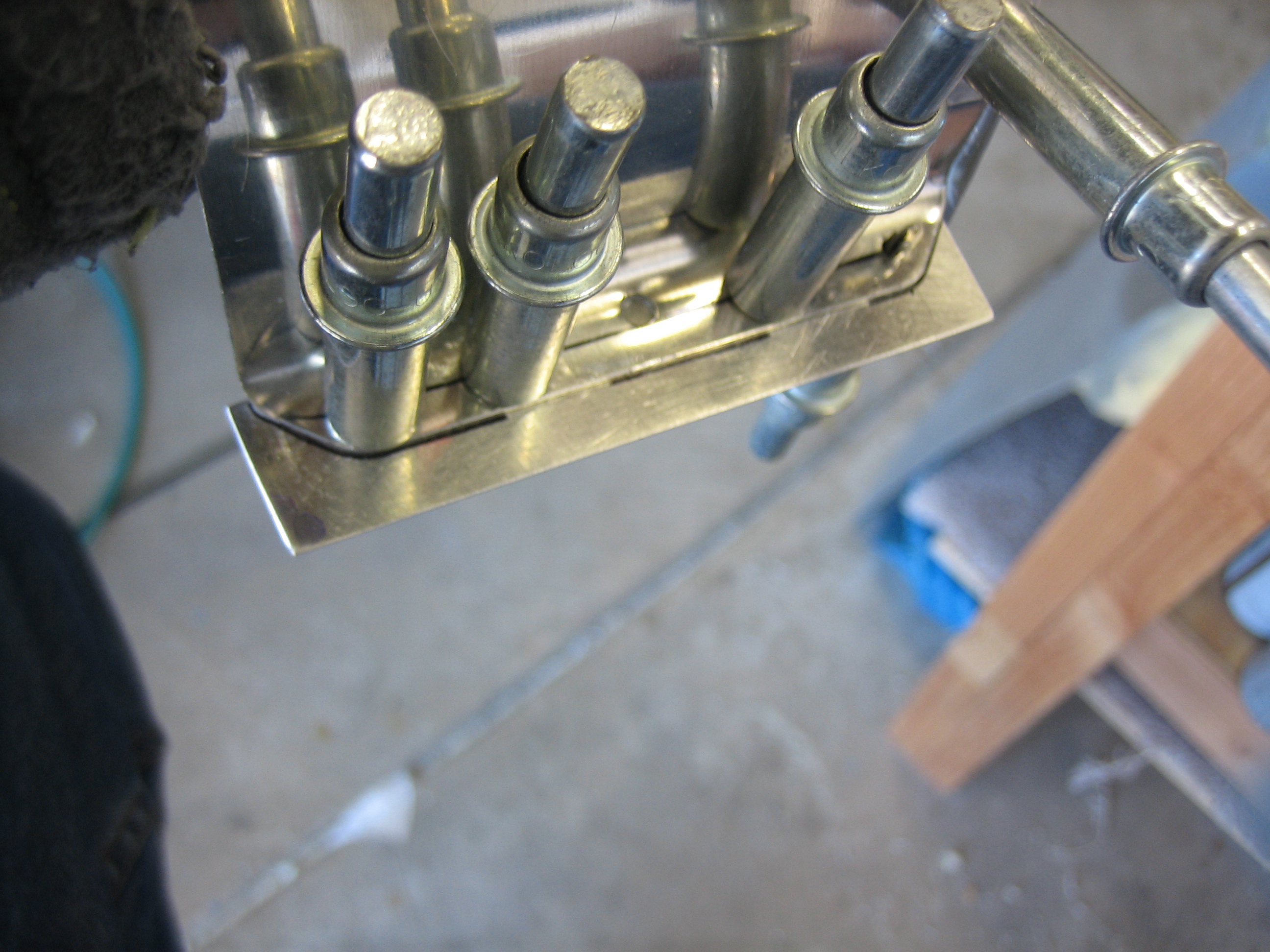
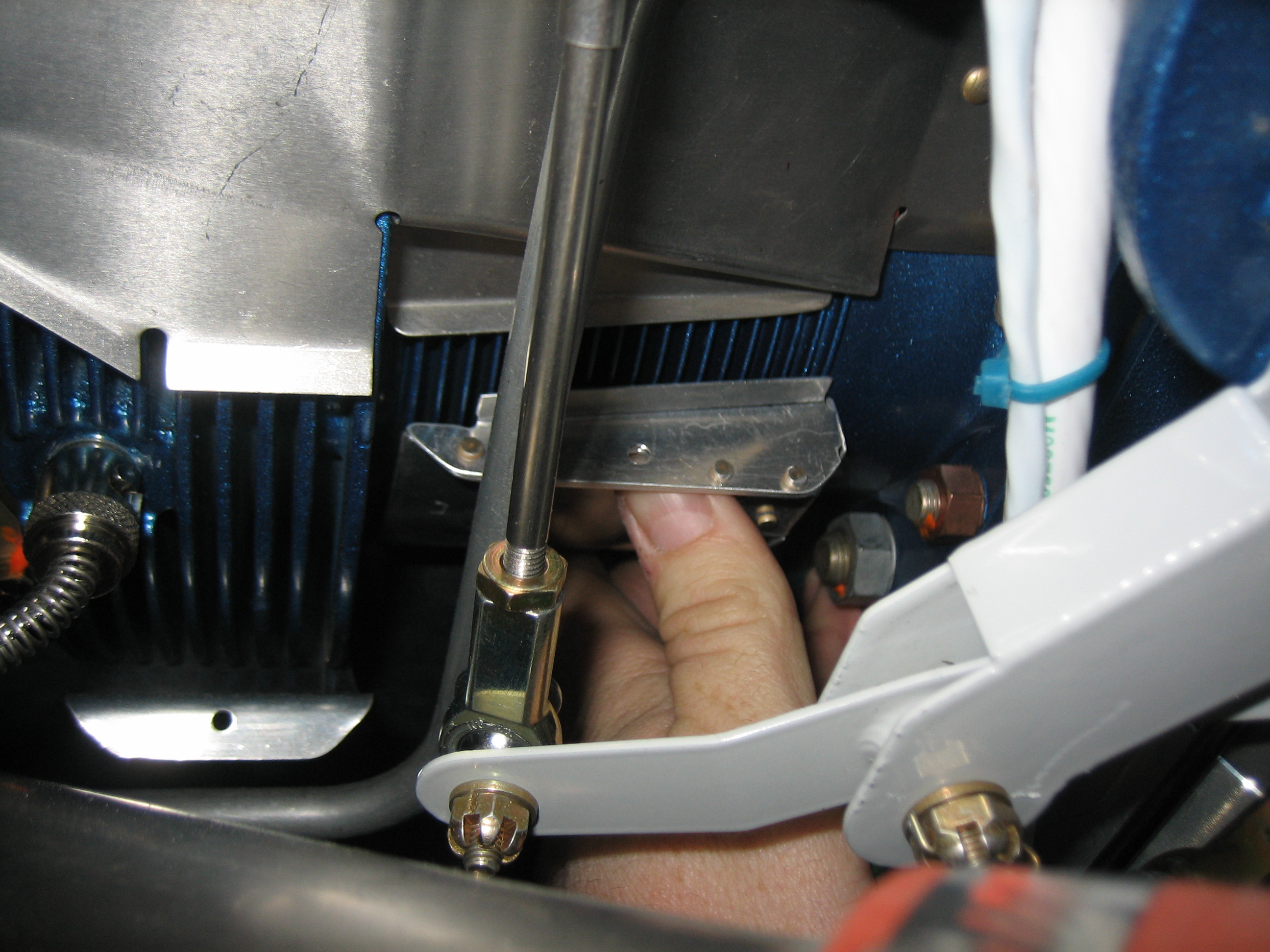
This picture gives you an idea how the shim follows the taper of the barrel fins.

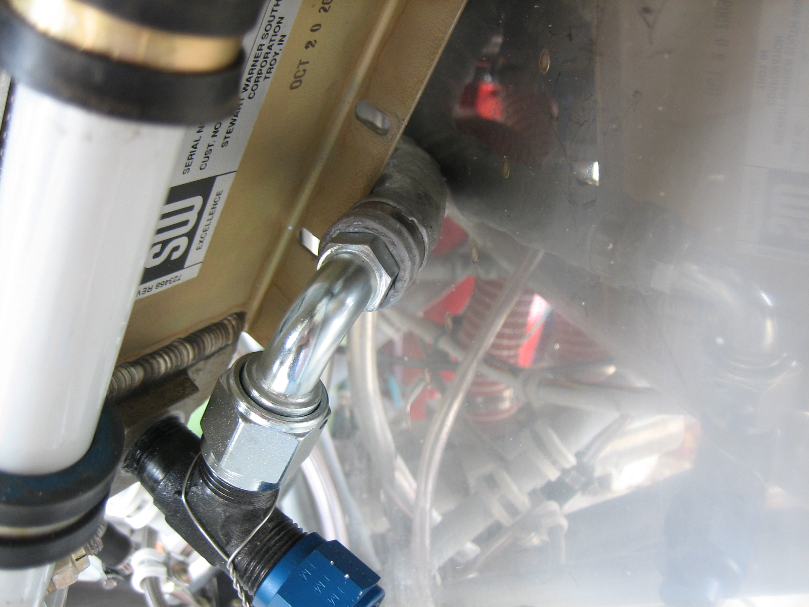
Here’s the completed #2 cylinder baffle mod.  I still have the #1 and #3 cylinders to do, but that will have to wait until tomorrow.

Installed Remaining Firewall-Forward Hoses and Finish Baffle Modifications for ECI Tapered Cylinders

My hopefully final hose order arrived from Bonaco today.  First up is the upper hose to the oil cooler.  This comes straight off the back of the engine above the left mag.  I’ll add a couple of adel clamps to tie the oil hose to the breather tube.  This will keep the hose from rubbing against the breather tube as well as stabilize the breather tube a bit better.

That hose runs just inside the forward engine mount tubes and connects to the upper oil cooler port.  I’ll add another adel clamp here to secure the oil hose to the engine mount.

The lower oil cooler hose routes around the back of the oil cooler and then connects to the 45º angle fitting above the propeller governor.  I’ll cut a relief in the oil cooler flange to keep this from abrading against the hose.  I may also add an adel clap to tie the hose to the firewall.

I also replaced the fuel pressure hose with one that has a 90º end on it to better clear the oil cooler.  I’ll also have to trim the oil cooler flange here to clear the hose.

After installing the hoses, I finished up the baffle mods.  Here’s the modification for the #1 cylinder.

And here’s the mod for the #3 cylinder.  Overall, these really weren’t that bad to make.  I probably spent 6-8 hours total fabricating and installing these.  I’d definitely recommend ditching the plans from ECI and just making your own templates.  You’ll have to do that anyway for cylinder #4, and it’s pretty quick to just do it all the way around.  I also highly recommend making them in two pieces and riveting them together with the single rivet in the corner.  This is much easier than trying to get all of the angles exactly right with the single piece that ECI specifies.

Put Together “The List”

I spent some time over the last couple of days putting together a list of all of the work necessary to complete the plane.  The current estimate is approximately 460 hours of work, but that includes work that many builders save until after first flight such as gear leg fairings and wheel pants.  I’m sure there are some missing items, so the list will likely get longer, but I think the estimates are fairly conservative.  At my current work level, that’s still over 6 months of time before first flight though.  I plan on doing my transition training with Mike Seager in OR as close as possible to first flight.  He’s booked up about 3 months in advance, but it doesn’t look like I need to schedule with him just yet.

Update: Wow, this estimate wasn’t even close. My first flight happened in February, 2014 (over two years after this entry was posted)!

Fabricated Left Conical Gusset and Front Ramp Support

I fabricated the right conical gusset tonight.  The way I formed these was to make a template out of stiff paper and transfer it to some 0.032″ 2024-T3 aluminum sheet.  I then marked the ends of the curved section and made a serial of small bends by clamping the gusset in a vise and hammering a small wooden block along the exposed face.  I then moved the gusset a degree or so and repeated the process until I reached the other end of the curved section.

Next, I riveted the mounting angle to the front ramp support.

This is attached to the side of the engine just behind the flywheel.

I then drilled and riveted the support to the front left ramp.  Notice that the center hole is left empty.  This is because the front baffle wall gusset will be riveted through this same hole.

Fabricated Front Ramp Brackets

I never liked the old tach cover (see this entry).  Although it was safety wired, that didn’t prevent it from unscrewing and bouncing around behind the engine.  I recently found out that Andair made this nice machined tach cover with integral o-ring.  I swapped it out and safety wired it to the same spot on the engine.  There’s no way this is coming off.

I fabricated the three front ramp support brackets.  This is the one that ties the right ramp to the right center baffle.  I left the bottom flange long on both ends until I know the left-right position of the vertical face.  I’ll then drill this to the right ramp and cut the ends of the flange parallel with the angle on the left.

These are the brackets that tie the left ramp to the left center baffle.  I positioned the vertical face against the side of the lower cowl inlet (with a piece of baffle seal between them) and then drilled the support on the left to lock in the position.  I then pulled the lower cowl and back drilled the support on the right through the existing hole in the ramp and support that sits just under the ramp.  I then pulled the bracket and drilled two more holes in line with that hole and then match drilled them to the ramp.  Getting all of this in the right position was a little tricky until I figured out the order, but everything worked out nicely.

I deburred everything and riveted the support brackets to the ramps and front center baffles.  The plans call for universal rivets here, but I might have to swap the rivets on the left bracket out for a flush head since the baffle seal material will rest here.

Here’s the bracket for the right ramp.

Riveted Conical Gussets

I finished drilling the side baffle flanges to the ramps and then deburred and dimpled everything.  After a quick priming of the mating surfaces, I riveted the conical gussets in place.  Here’s the right gusset.  I also riveted the little clip in the upper right of the picture to the side baffle.

Here’s the right conical gusset.  These ended up fitting really nicely.  There quite a bit harder to install now since they’re so big.  They wrap from the centerline of the engine just behind the prop around the side of the engine and back past the front-most cylinders.

Worked on Baffle Connecting Rods

The bottom of the baffles need to be tied together to keep them tight against the cylinder fins.  You can either do this by using safety wire through some washers (to keep the safety wire from sawing through the aluminum baffles) and a piece of plastic tubing (to keep the safety wire from sawing through the cylinder head oil return lines.  I’m sure this works fine, but it seems pretty cheesy.  The other suggested approach is to use some stainless steel rod, bent to clear the cylinder head oil return lines and threaded for 6-32 nuts on each end.  I got started by fabricating the left outboard connecting rod.  This needed to be a little longer than the plans specified, and the angle of the bends at each end differs from the plans to make the threaded ends sit perpendicular to the baffle flanges.  I installed the optional plastic tubing to ensure that there would be no abrasion if this contacted the oil return line.  I tried threading the end, but the shitty Harbor Freight tap and die set I have is really junk.  I basically stripped the threads on the 6-32 die.  This junk is okay for creating threads on aluminum, but I need a decent tap and die set to do stainless steel.

Started Threading Baffle Connecting Rods

I picked up a much better tap and die set from Sears today and was able to easily thread the ends of the stainless steel rod I bent yesterday.  Unfortunately, the die cuts the threads a little deeper than a typical 6-32 screw, so the all-metal self-locking MS21042 nut spins freely.  I’ll have to further distort the threads in a vice to ensure these are self-locking.