Finished Flap Position Sensor Installation

I wrapped up the flap position sensor installation tonight.  I installed the 4-40 threaded rod between the bracket I fabricated and the position sensor and adjusted the length so that it moves the position sensor arm through the full range of travel.  I then installed a couple of locking jam nuts to keep the rod from moving.

Next, I configured the flaps with a couple of intermediate stop points.  I’ll duplicate these settings in the VP-X so that it will automatically stop at these points when I tap the flaps switch.  I probably won’t enable that feature during initial flight testing though.  Here’s the indication when the flaps are all the way up.

…and here’s the indication when the flaps are all the way down.

Installed Heater Control Cable

I installed the heater control box cable tonight.  The control is mounted on the far right of the instrument panel which provides for a fairly easy routing.  The cable curves down over the rudder bars and is attached to one of the firewall support angles with an adel MS21919-WDG3 adel clamp and then passes through a 1/4″ hole in the vertical firewall support angle behind the wire bundle.

The housing will be anchored with another adel clamp to the bolt on the right and the protruding wire will attach to the b-nut on the flapper arm.  There’s no point hooking these up now since the control cable has to be removed when the instrument panel comes out for paint and labeling.

Started Working on Wingtip Lights

I started working on the wingtip lights tonight.  I’m going to fabricate a reflective backing for both sides of the recess, so I was fairly generous with the cutout so that I can easily position the light.  I’ll trim the backing to tightly follow the lights.  I don’t want to determine the final position until the nav/strobe light is attached and the lens cover is trimmed so that I can make sure there is no interference.  This is approximately where the light will end up though.  The is substantially farther forward than the stock lights which should provide better lighting directly in front of the plane.  The stock light position puts the bulbs a good 4″ farther aft which causes the side of the recess to shade the area directly in front of the plane.

Once I have the lens trimmed, it looks like I can probably push the light even farther forward.  I’m going to try and get it within about 1/4″ of the lens.  Since the light runs really cool, I don’t have to worry about overheating the lens on the ground.  In flight, there’s obviously enough airflow that I wouldn’t have to worry about heat anyway.

I adjusted the lens until it looked like it would precisely follow the curvature of the outer edge of the wingtip and then taped it down.  I used some masking tape to mark the cut line.  The lens will pull back farther after it’s cut, so this will just be a preliminary cut line.

I played with some tin snips along the edge, and they made perfect cuts without any hint of cracking the plastic, so I used them to cut out the lens.  This was far better than using the cutoff wheel since I could basically trim right to the line and then touch up the edge with some sandpaper to remove any microscopic burrs that could create stress risers and lead to cracks down the road.

With one edge of the lens aligned with the flange around the recess, it looks like I’ll need to trim about 1/8″ off of the other edge to allow it to drop behind the lip.

Worked on Nav/Strobe Lights

My Nav/Strobe Lights arrived from Aircraft Spruce today.  I used the adaptor plate and gasket and installed them to the landing/taxi light housing.  I hooked them up to the plane to verify everything works properly.  Holy shit these things are bright.  You can’t be looking anywhere near these things when the strobes go off; it is blinding.

Next up, I drilled the rudder bottom fairing and installed a couple of 4-40 nylock nuts.

I anchored the nuts using a couple of screws and some safety wire.

I then mixed up some 5 minute epoxy with flox and covered the nuts to anchor them inside the fairing.  After the flox cured, I removed the screws and temporarily installed the tail light to ensure the nuts were secure.

Finally, I took one of the lights and installed a waterproof molex connector so that all of the connections can be made at once when installing the wingtip.  I was only able to do this on one of the lights before running out of steam.

More Work on the Oil Door

I drilled some extra holes in the hinges and then mixed up some epoxy and flox.  I glued and then riveted the hinge on with some soft rivets.

Next, I cut holes for a couple of Hartwell latches.  These are perfectly flush with the surface of the oil door and hold it really tight.  These needed to be mounted in this orientation because of the curvature of the oil door.

Worked on Tail Light and Oil Door

I installed a connector on the tail light along with a piece of heat shrink over the wires.  Once the rudder is installed permanently, I’ll install this on the bottom fairing and hook it up.

I decided to make a little progress on the oil door tonight.  I fabricated a spacer out of 0.063″ aluminum to pull the oil door in tighter at the hinge line.

You can see at the hinge line that the door is in nice and tight.  Without that spacer, the flexibility of the door and the force of the hinge spring was causing the door to bow out just slightly here.

Glassed Cowl Door Components

I mixed up some epoxy/flox and riveted on the oil door latches.  I then placed a couple of layers of 8 oz cloth with a 1/8″ fiber core for stiffness.  This will substantially stiffen the oil door to prevent it from bowing out in flight.  To ensure an even tighter seal, I’ve slightly flattened the oil door (that’s what the blue tape is doing).  This will ensure that when the bottom is latched, the middle of the door will be tightly pressed against the cowl.

I also put a couple of layers of fiberglass over the side of the hinge bonded to the cowl.  The top layer you see in both layups is peel-ply to wick away excess resin.

Worked on Oil Door and Oil Cooler Plenum

I took off the peel-ply and cleaned up the fiberglass a bit.  I’ll need to do a bit more work to clean this up, but it made a big difference in the door stiffness already.

I picked up some two-part expanding polyurethane foam at TAP Plastics and poured some in a box that looked about the right size to form the oil cooler plenum.  This needs 24 hours to cure before I can start shaping it.  I fully expect that this first piece will be practice, and I’ll have to make another plug before I can layup the fiberglass over it.

Worked on Oil Cooler and Fuel Overflow

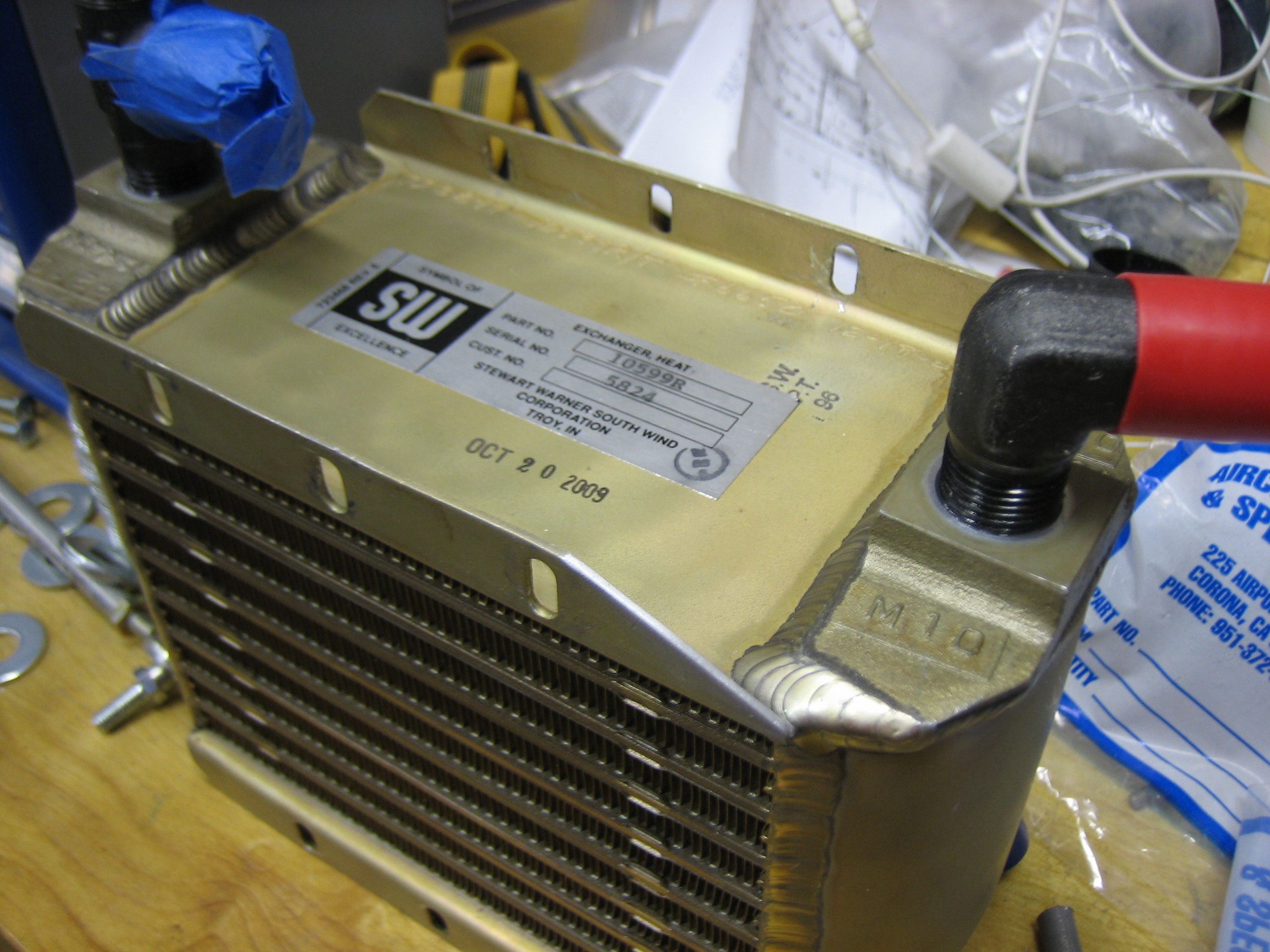
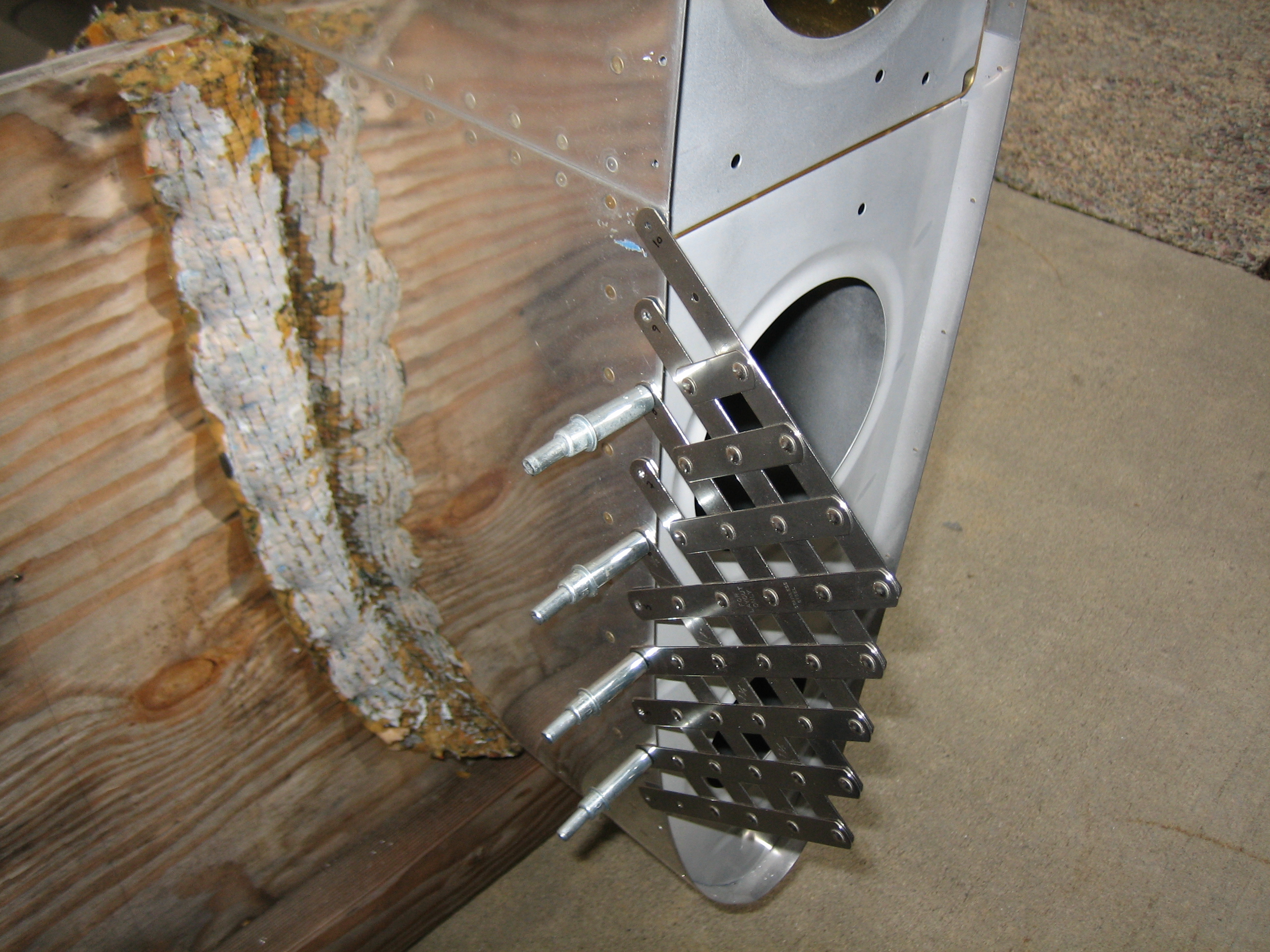
I installed the fittings in the oil cooler tonight.  The top fitting is a standard AN822-8 elbow, but the bottom fitting is an AN826-8 tee with the pipe thread on the run.  You can also see that I trimmed part of the oil cooler flange to provide a little more clearance with the firewall.

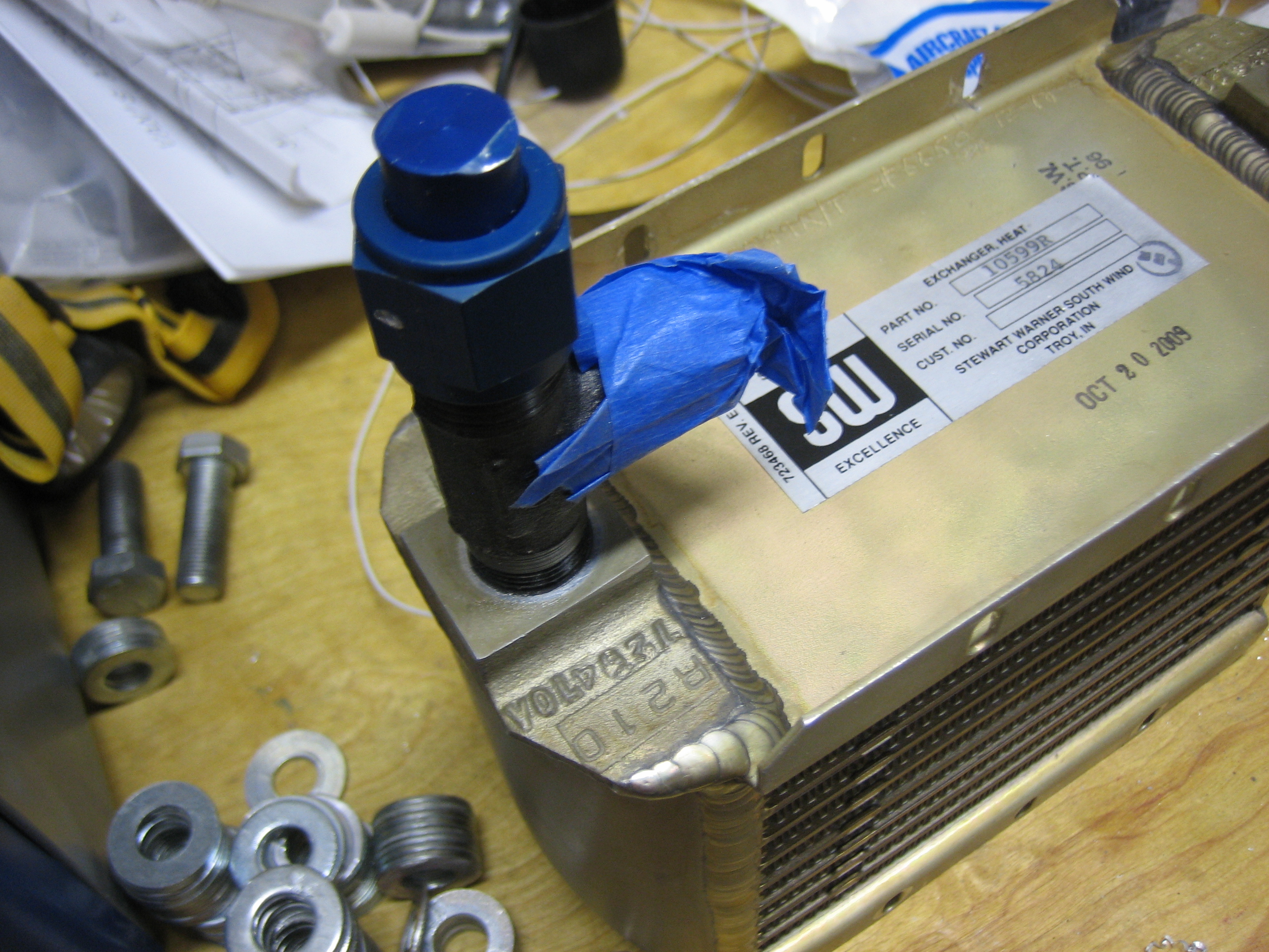
Here’s a better shot of the tee fitting.  The blue tape covers the flare port that will connect to one of the oil cooler lines to the engine.  The other flare port has an AN929-8D cap that can be removed during oil changes to drain the oil from the cooler and lines.  Without this, at least a quart of oil would remain in the cooler and lines during an oil change.

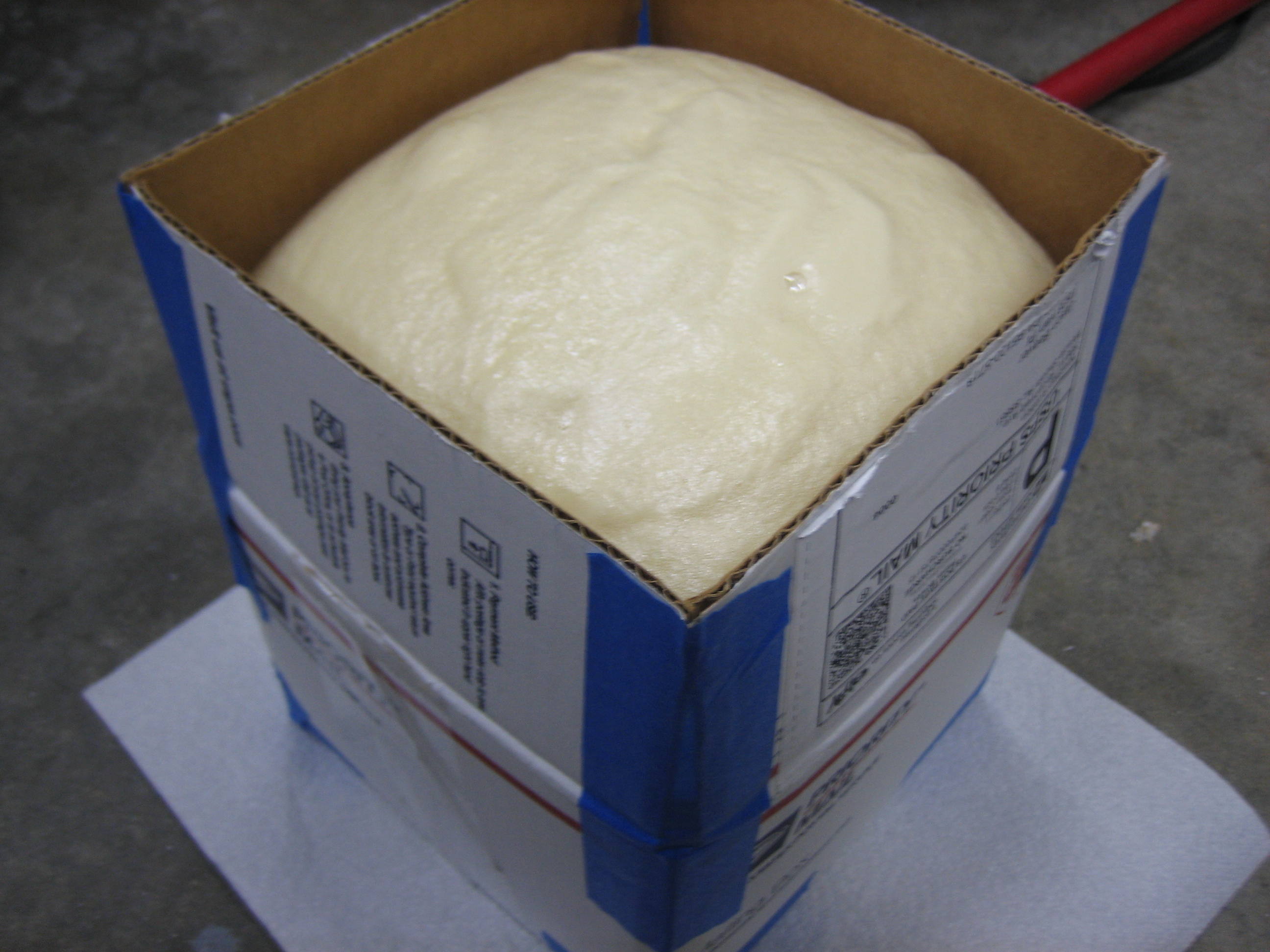
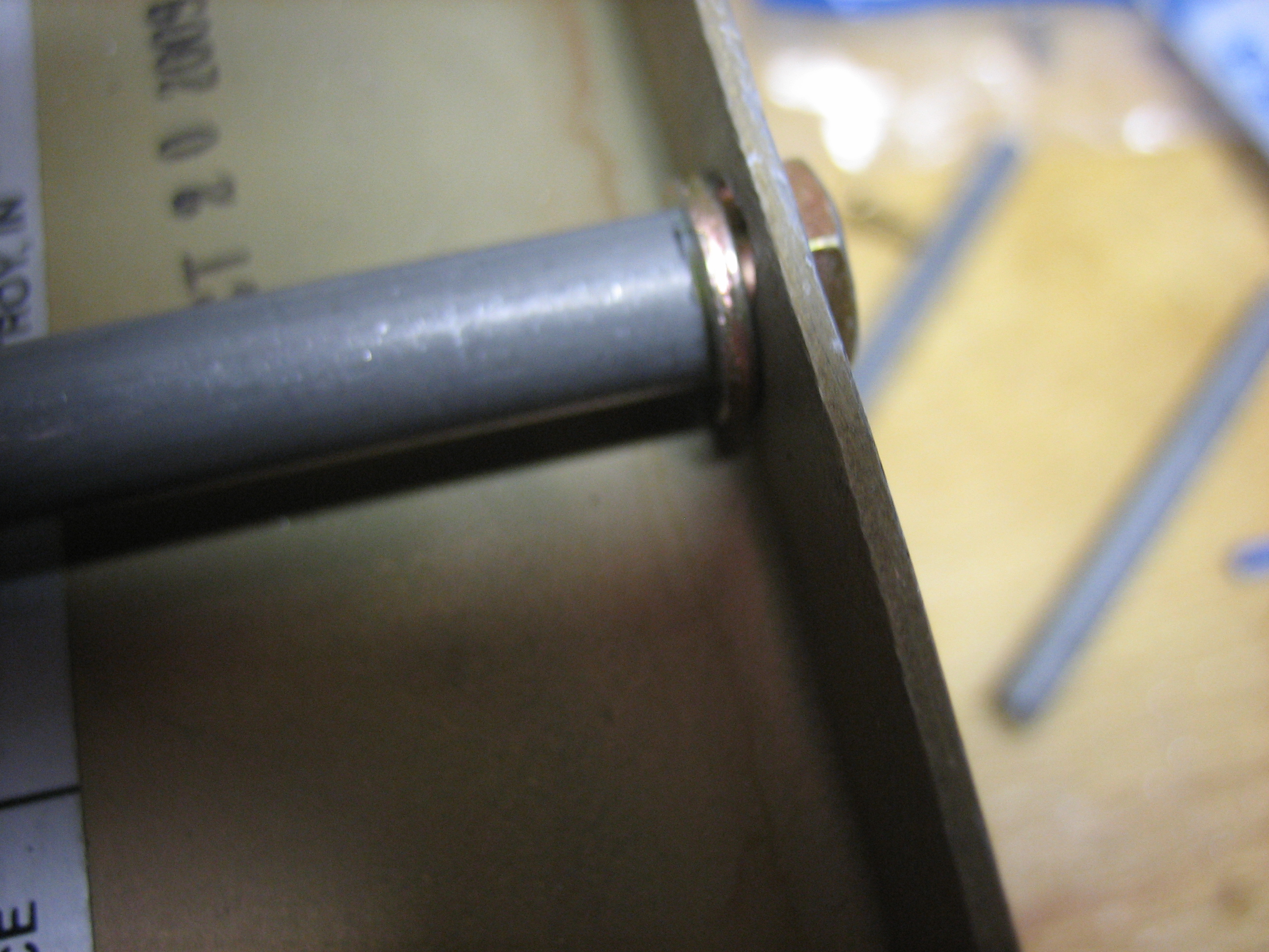
I fabricated three spacers that will used when installing the oil cooler.

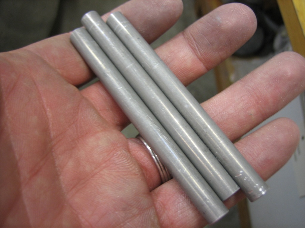
They will fit between the flanges (along with some washers) to allow the mounting bolts to support both the front and back sides of the oil cooler.

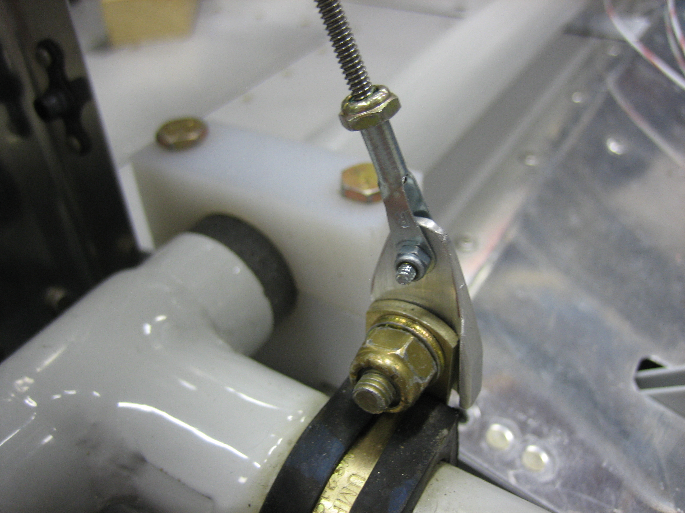
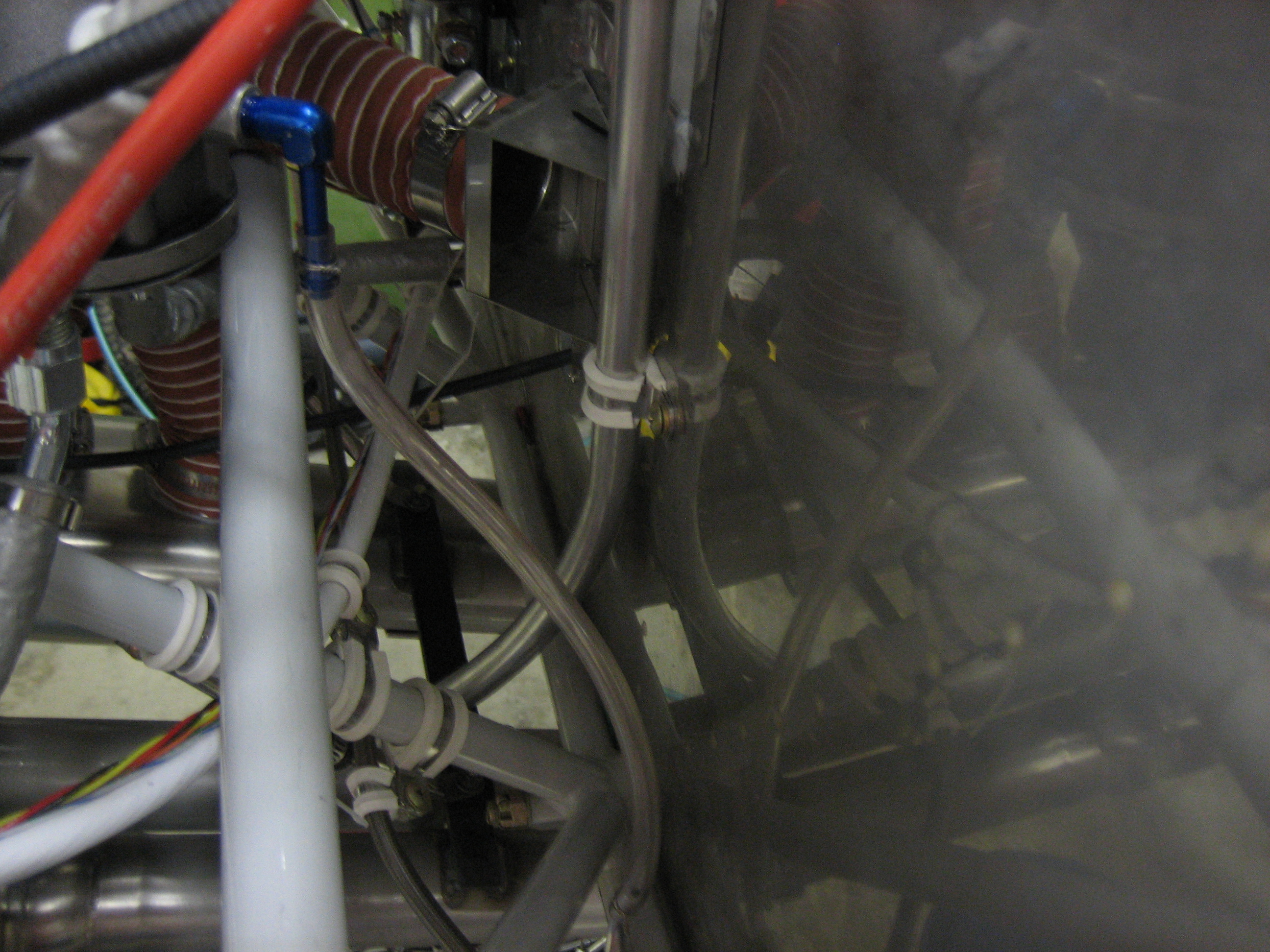
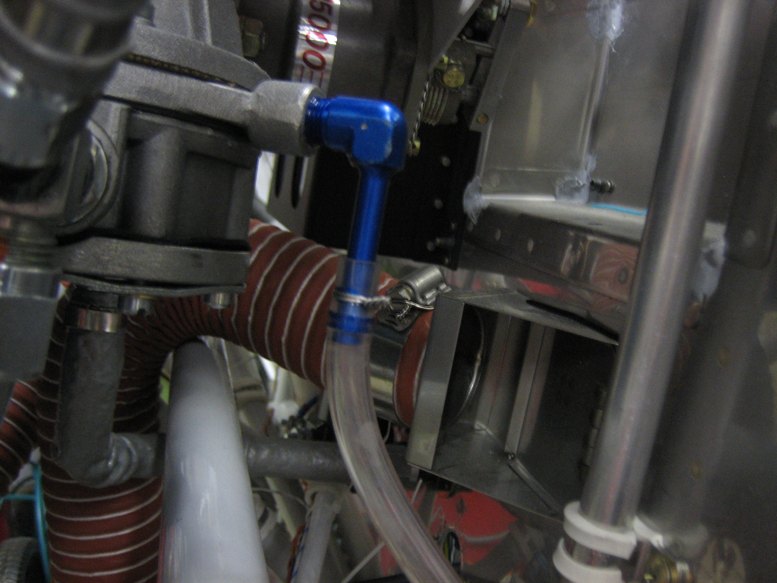
I fabricated a small oil cooler support plate and painted it (I’ll show a picture tomorrow).  While waiting for the paint to dry, I decided to install the fuel overflow tubing.  I used a piece of 1/4″ ID Tygon tubing to run from the AN842-4D fitting on the fuel pump down to a piece of 1/4″ tubing on the firewall.

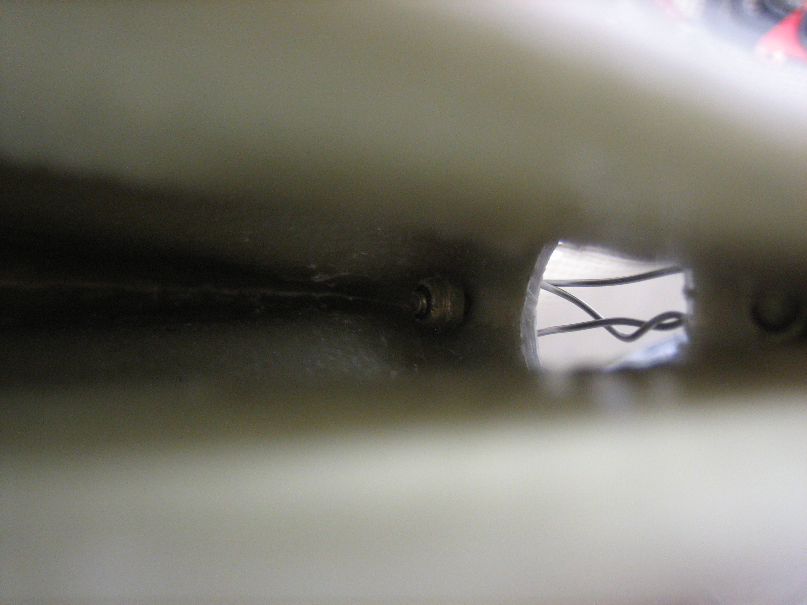
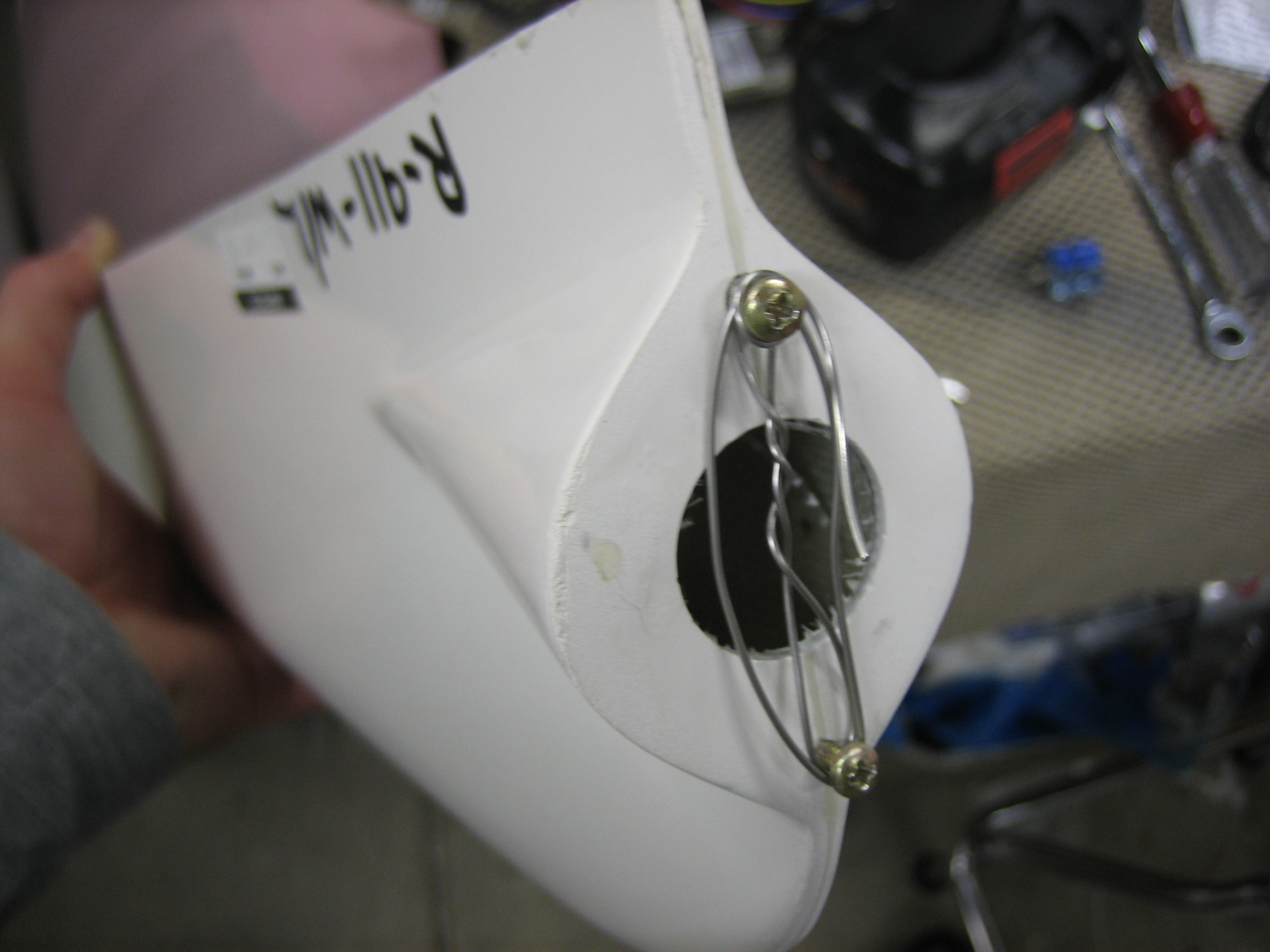
The tubing is held on to the fitting with a piece of safety wire that is double wrapped around the tubing.

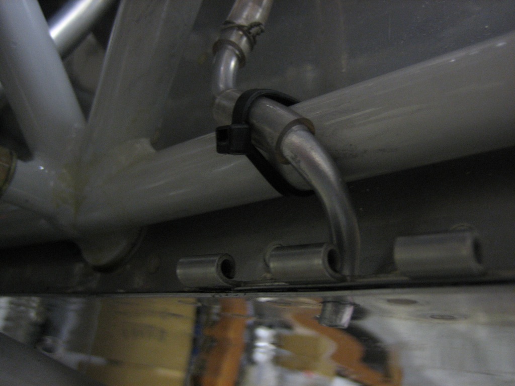
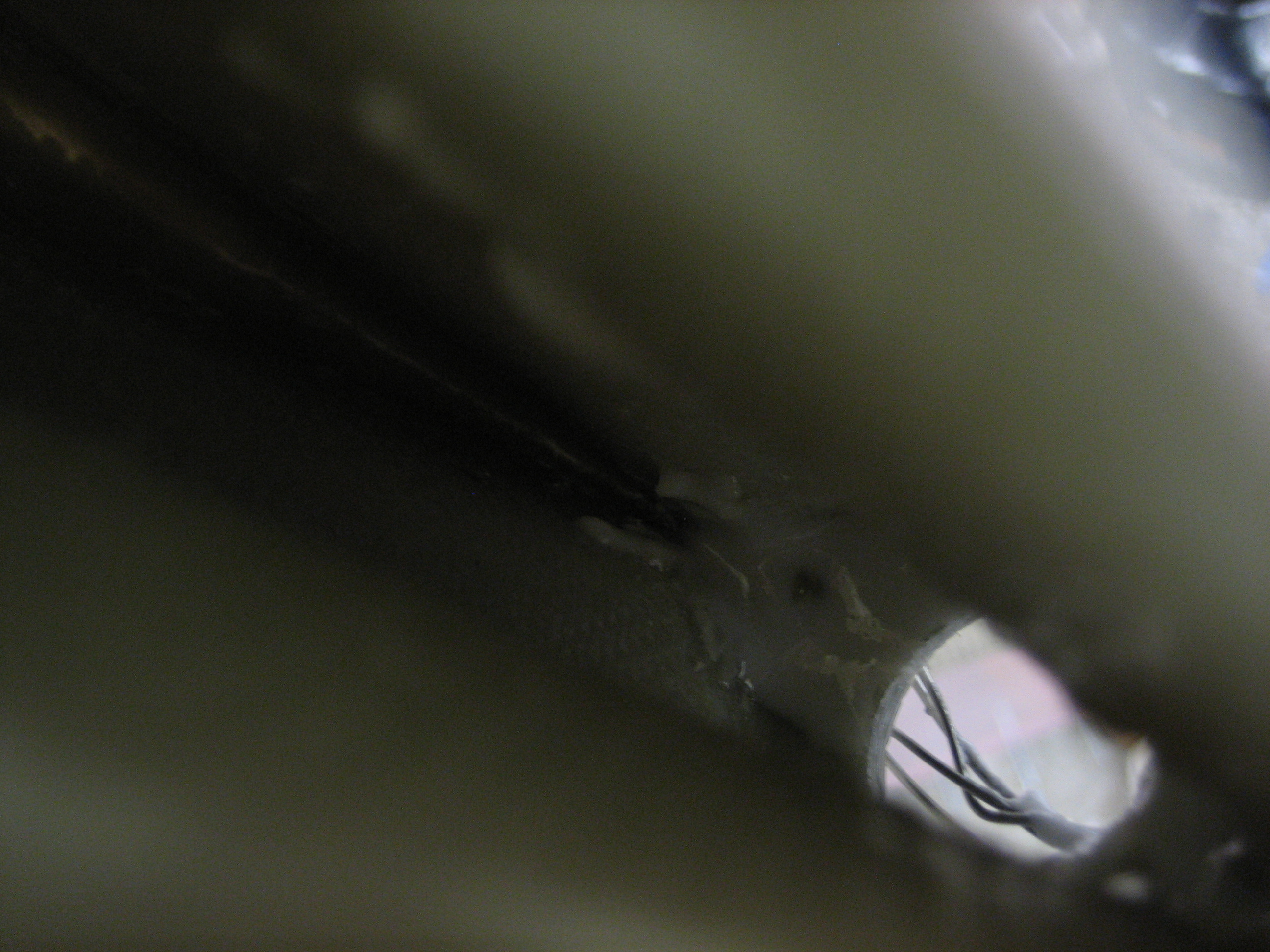
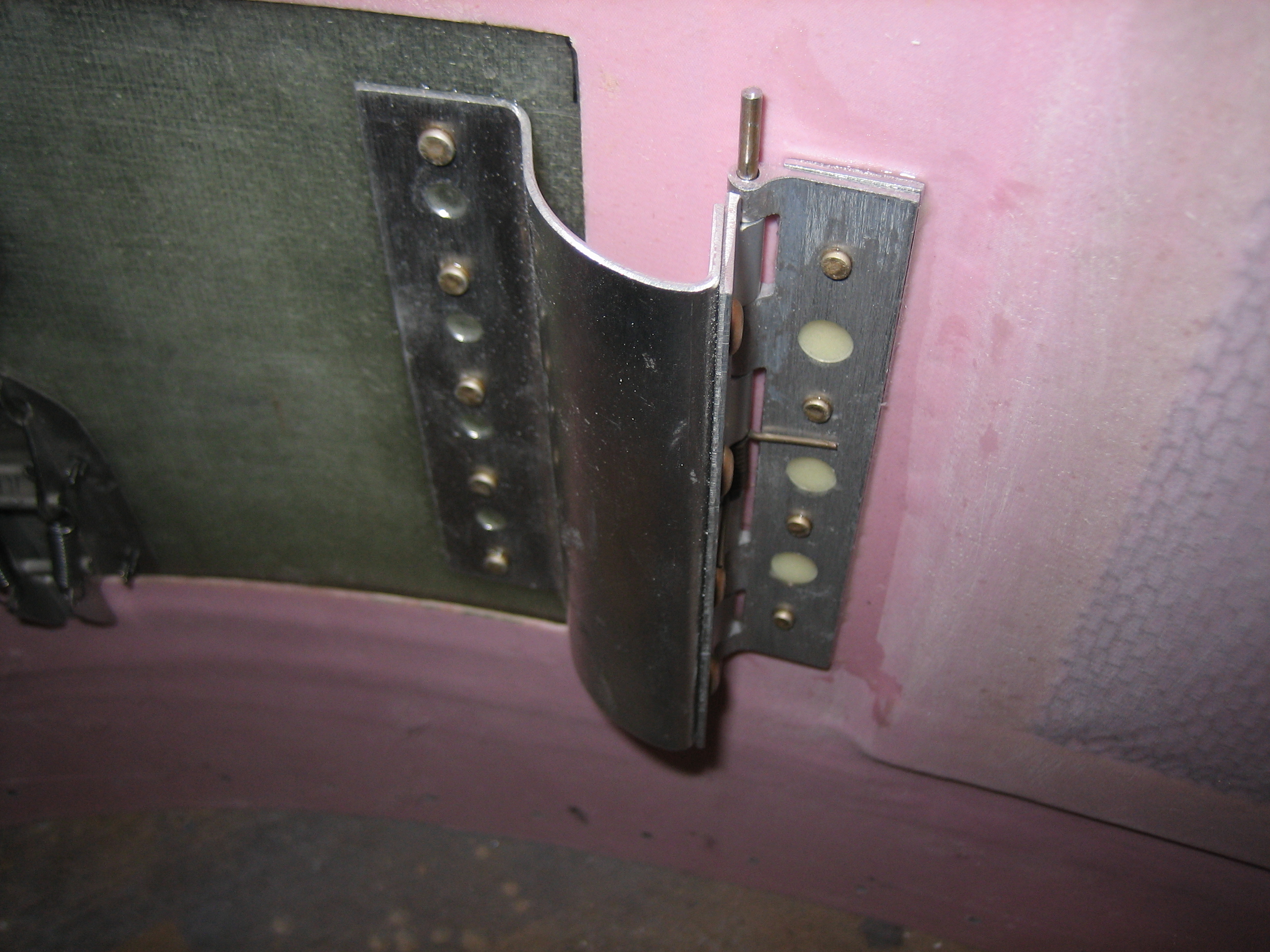
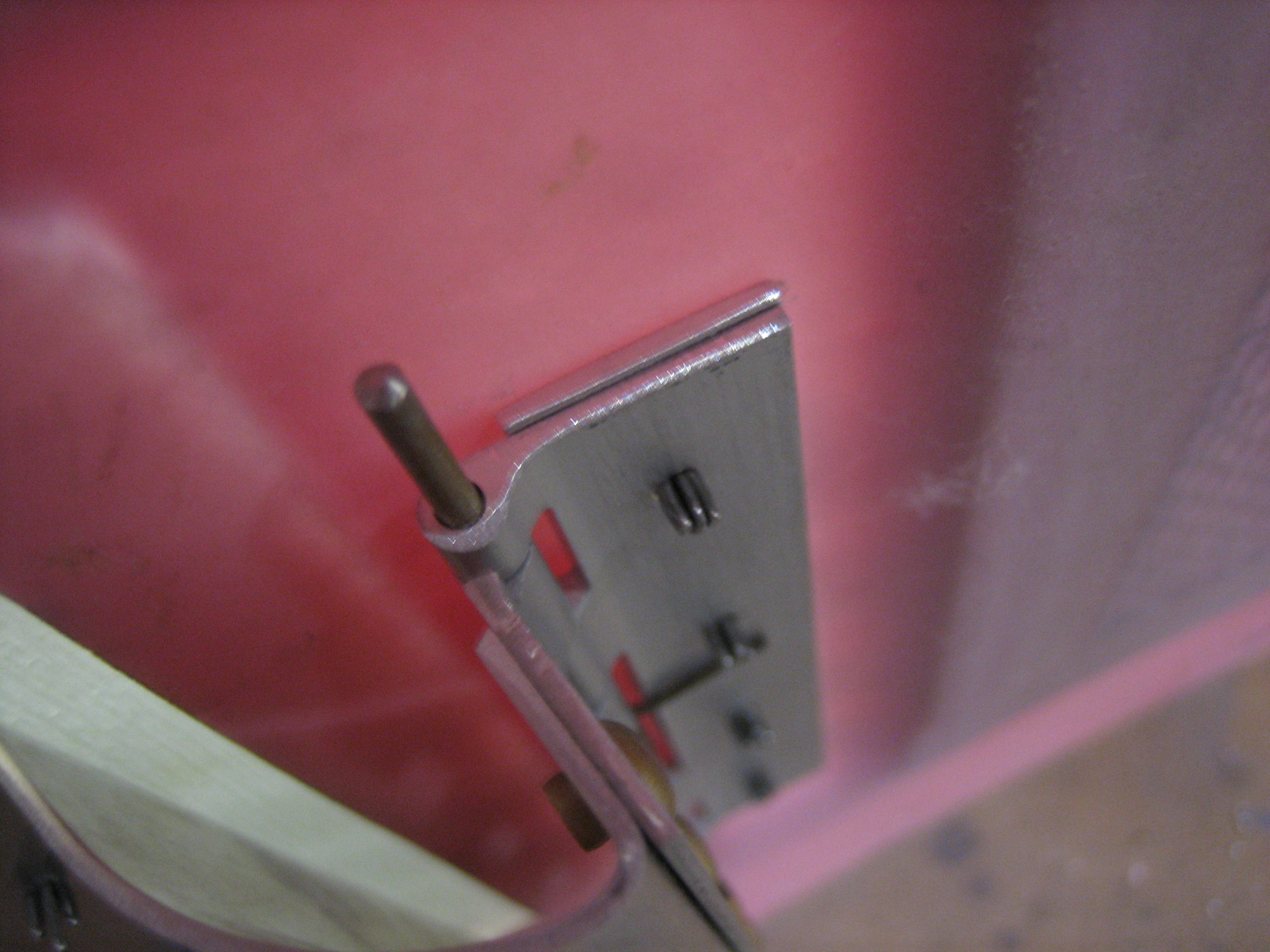
At the bottom end, I bent a short piece of 1/4″ soft aluminum tubing so that it cleared the engine mount tube and poked through a 1/4″ hole I drilled through the firewall flange and hinge.  I slipped a short piece of Tygon tubing over the aluminum tubing and zip-tied it to the engine mount.  I then used some safety wire to attach the Tygon tubing from the fuel pump to the other end of the aluminum tubing.

Drilled Wings for Wingtips

I’m going to be using hinges to attach my wingtips.  This necessitates drilling additional holes in the end of the wing so that the hinges are attached with rivets spaced more closely together.  Most of the holes already pushed in the end of the wing skins were about 2.5″ apart, so I used a rivet spacer to drill additional holes between the pre-punched holes.  The hinges need to be spaced back a bit to account for the thickness of the fiberglass tips.  I’m going to use 2 layers of 0.025″ alclad, so I laid out and started cutting the strips.  This was brutal on my hands though, so I didn’t get through all of them tonight.