No pictures tonight, but I hooked up one of the GTN serial inputs to one of the SkyView serial outputs so that the SkyView can share traffic information with the GTN. I configured the SkyView to output TIS traffic, but it wasn’t clear how to configure the GTN to receive the traffic. I tried configuring it as a GTX with TIS, but then it wanted to put a transponder control box on the screen (though it had a red X through it). I’ll need to ask on the Dynon forums to see if anyone has any ideas.
Prepped Wings for Riveting
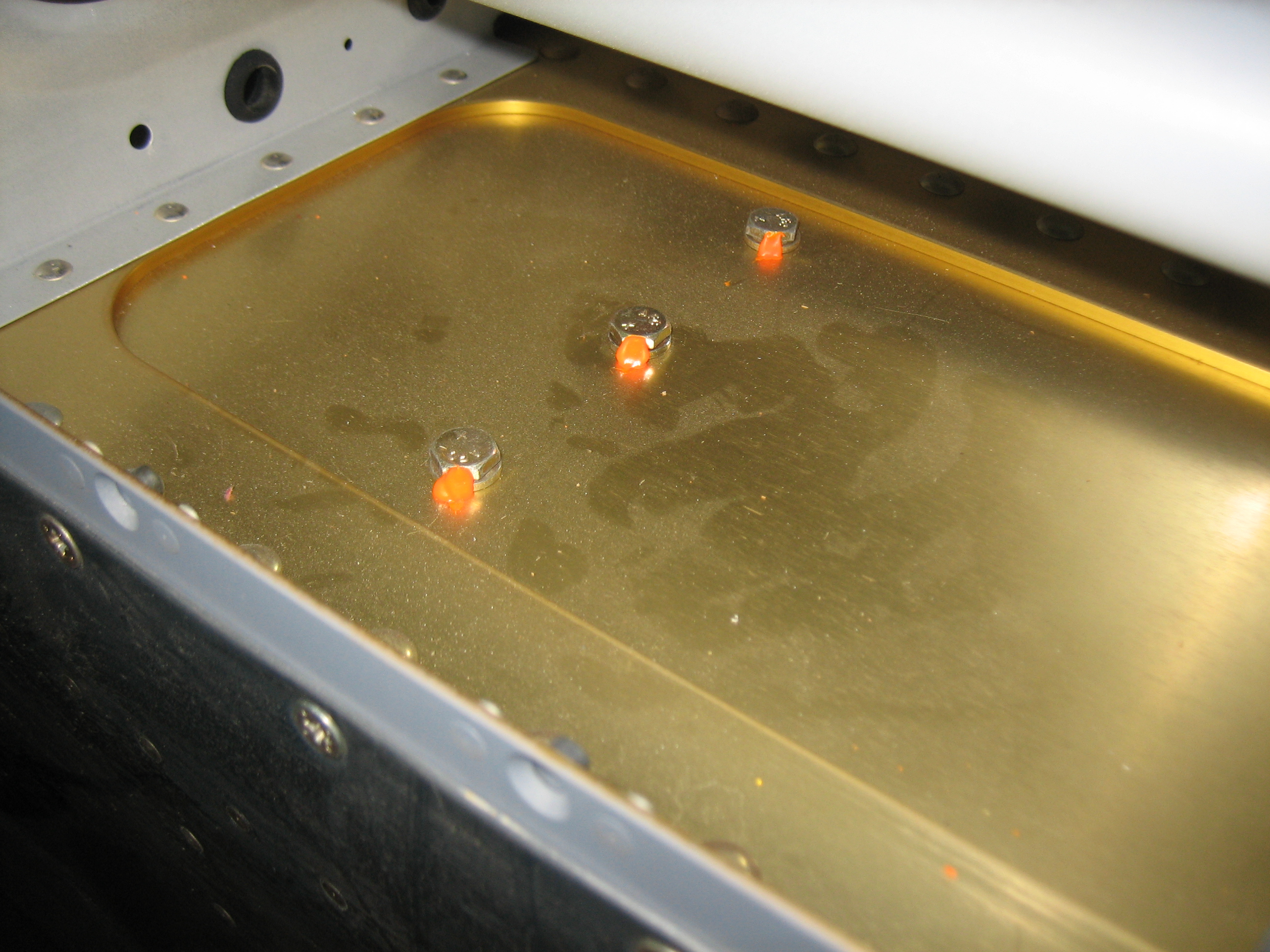
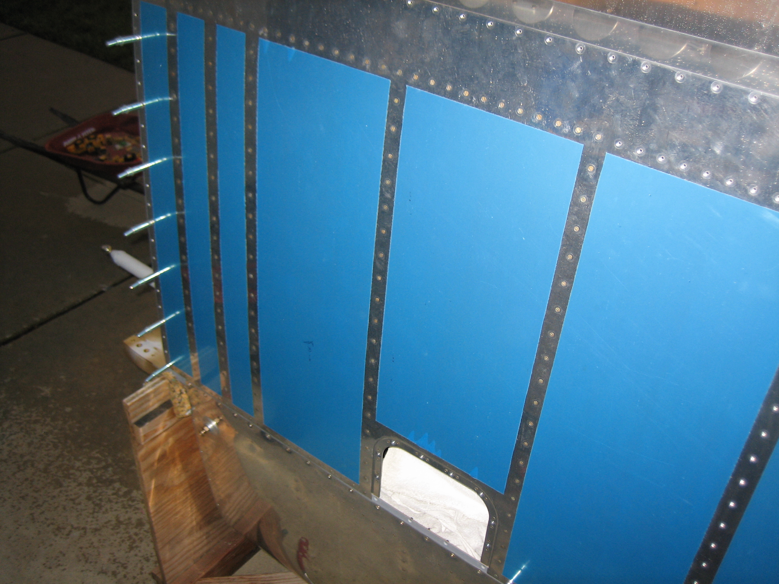
In preparation for riveting on the wing bottom skins, I wanted to take care of a few last items inside the wings. First up, I installed the remaining fuel tank z-bracket bolts and torqued/sealed them. Afterward, I installed the remaining screws that attach the tank (only on the bottom of each wing since that’s all I could reach). I also cleaned out each bay and stripped the plastic from the insides of the wing skins.
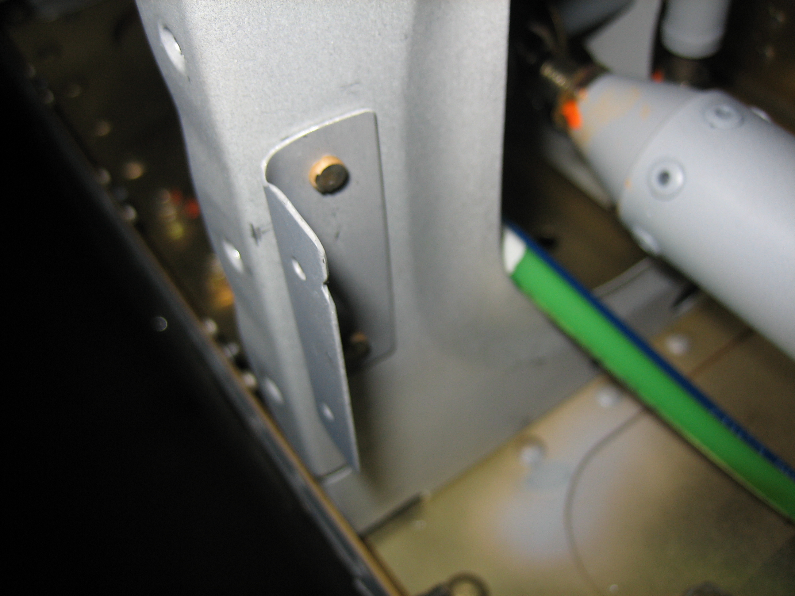
This bracket ties the pitot tube mount to the adjacent rib. I primed it and riveted it to the rib with some AN470 AD3-4 rivets.
Finally, I installed the countersunk nutplates on the top side of each wing aft of the spar. I’ll do the bottom side of the wing aft of the spar after the bottom skins are riveted on. The nutplates around the inboard edge of the tank will have to wait until I can remove the wings from the stand.
Started Riveting Wing Bottom Skins
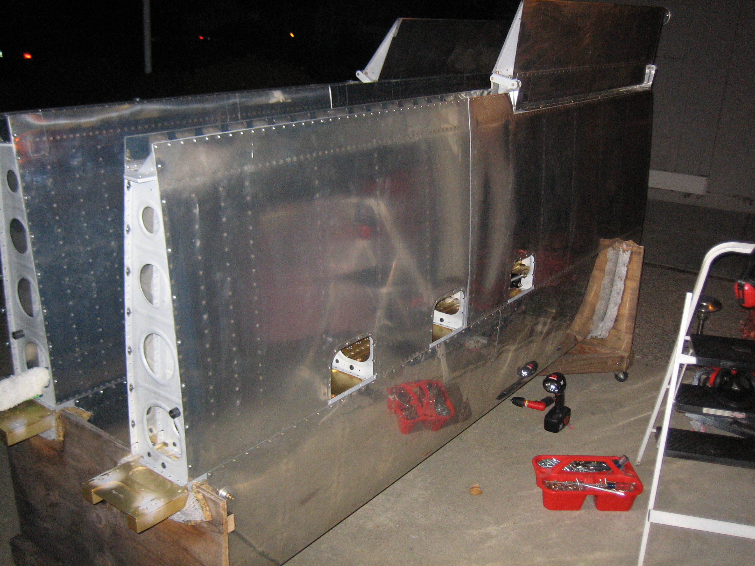
My buddy Andre stopped by and we got started riveting the inboard bottom wing skin on the right wing. We got all of the rivets in the wing walk ribs (the four closely spaced ribs on the left of the picture) except for the last rib which is easy to reach with the squeezer. We also finished up the next two ribs on either side of the inner inspection cover. This took us roughly 2.5 hours. It seems like such a small amount of riveting for this much time, but some of these rivets were really tough to reach and required multiple tries to get the bucking bar on them. The rest of the bays should be a bit easier to reach.
I came back out later in the night and decided to get the wing root fairings prepped. I cleaned up the remaining edges and dimpled the holes for #8 screws. These can now go on the shelf until I get to the airport and the wings are on for good.
Finished Skinning Right Wing
Andre stopped by today and helped me finish riveting the bottom of the right wing. We had a little scare when the holes wouldn’t align correctly. Basically, if the rear spar holes were clecoed in place, the forward spar holes were off by about 1/32″ or so. The holes in the substructure were farther apart than the holes in the skin. I finally determined that the flanges at the ends of the ribs can flex a little bit and pulling down on the rear spar compressed these flanges enough to allow me to pull the holes into alignment. The outer skin is definitely easier than the inner skin. There is a lot more room between the ribs, and we changed our strategy to rivet the rear spar first while I could reach straight up from below in each bay. It still took us probably 4-5 hours to finish off this wing.
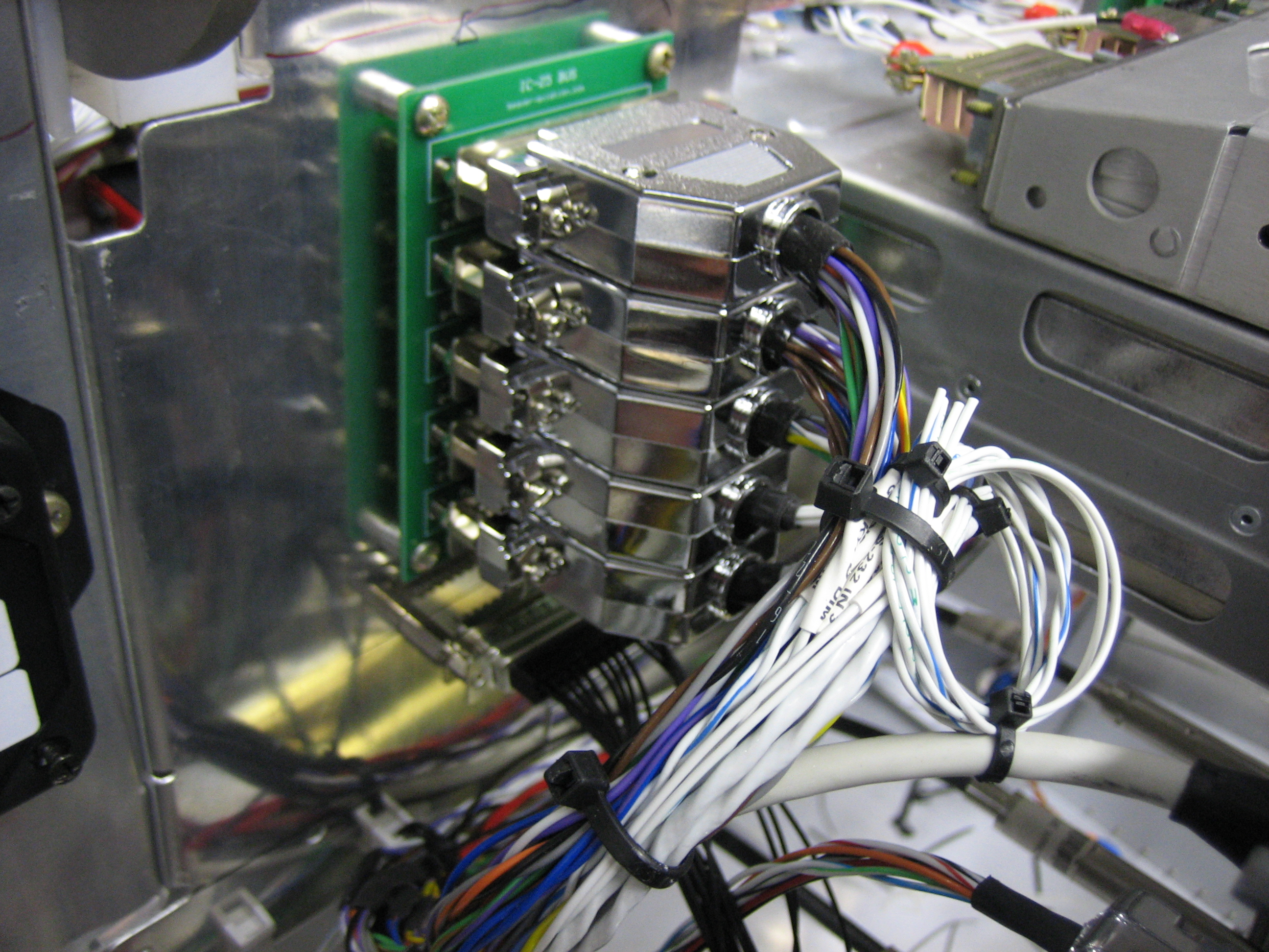
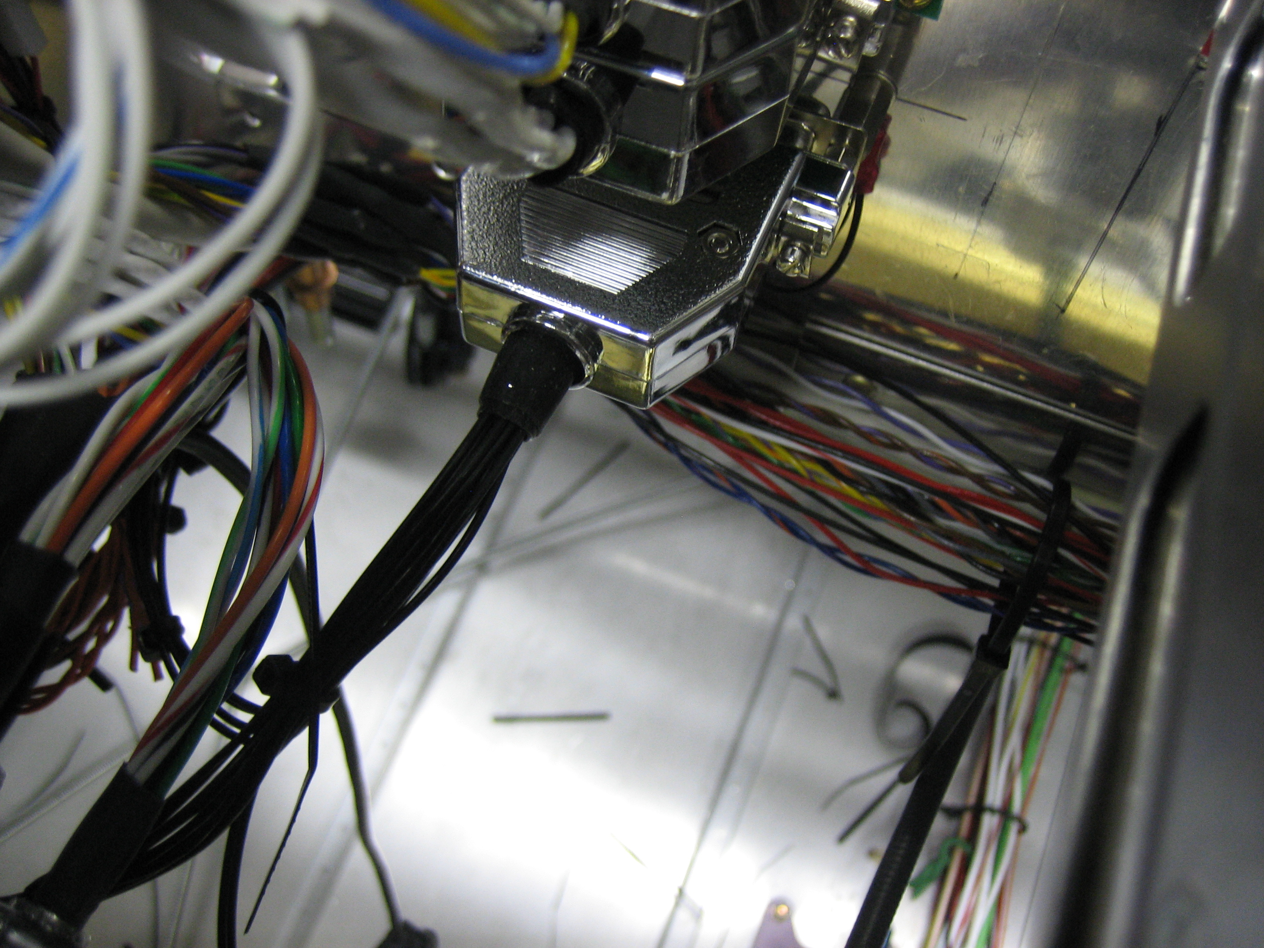
Installed Avionics Interconnect DB-25 Shells
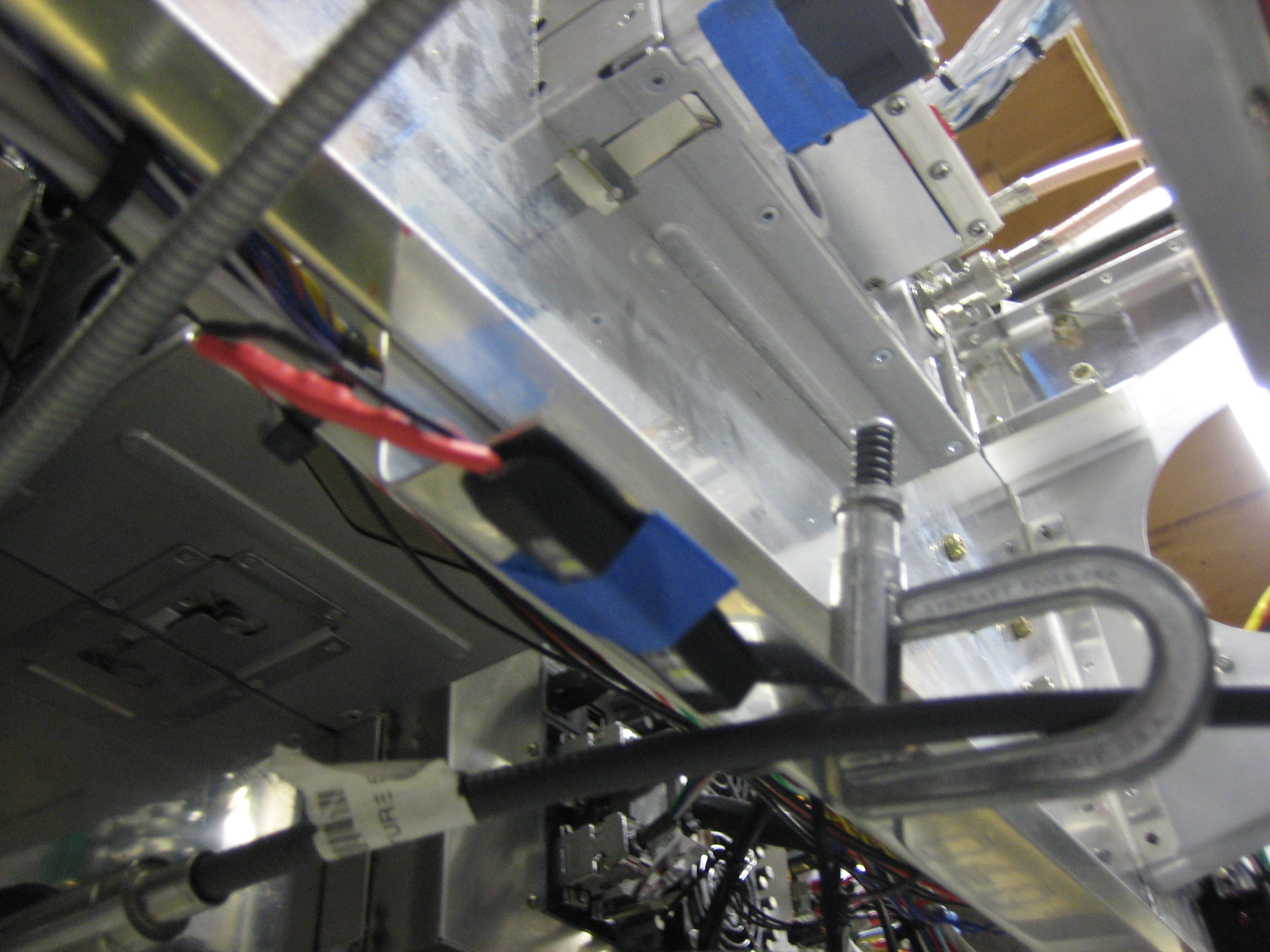
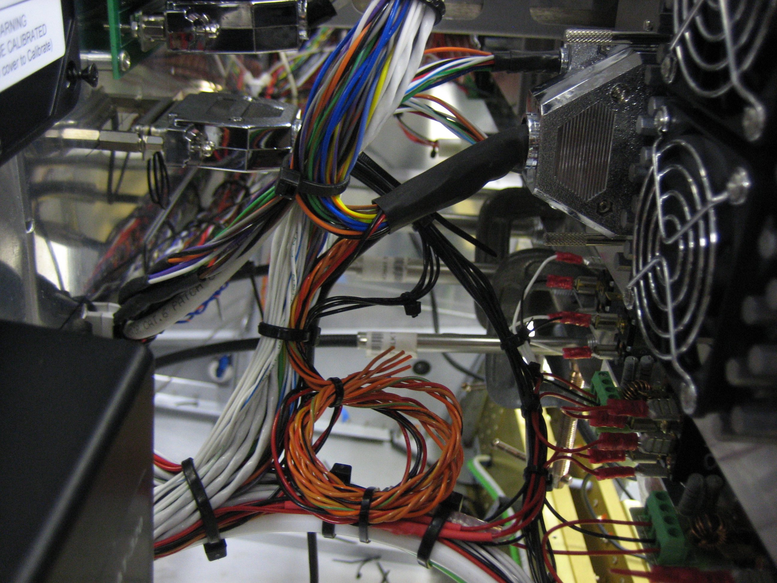
I installed the last few wires in the avionics interconnect connectors and then installed the shells. Afterward, I tidied up the wiring bundles a bit. The loops of extra wires there are the other two (currently) unused GTN serial input lines and the dimming bus wires from the GTN and audio panel in case I choose to hook them up to the SkyView at some point.
Installed Aileron Pushrod Boots and Gemini Pitot Tubing
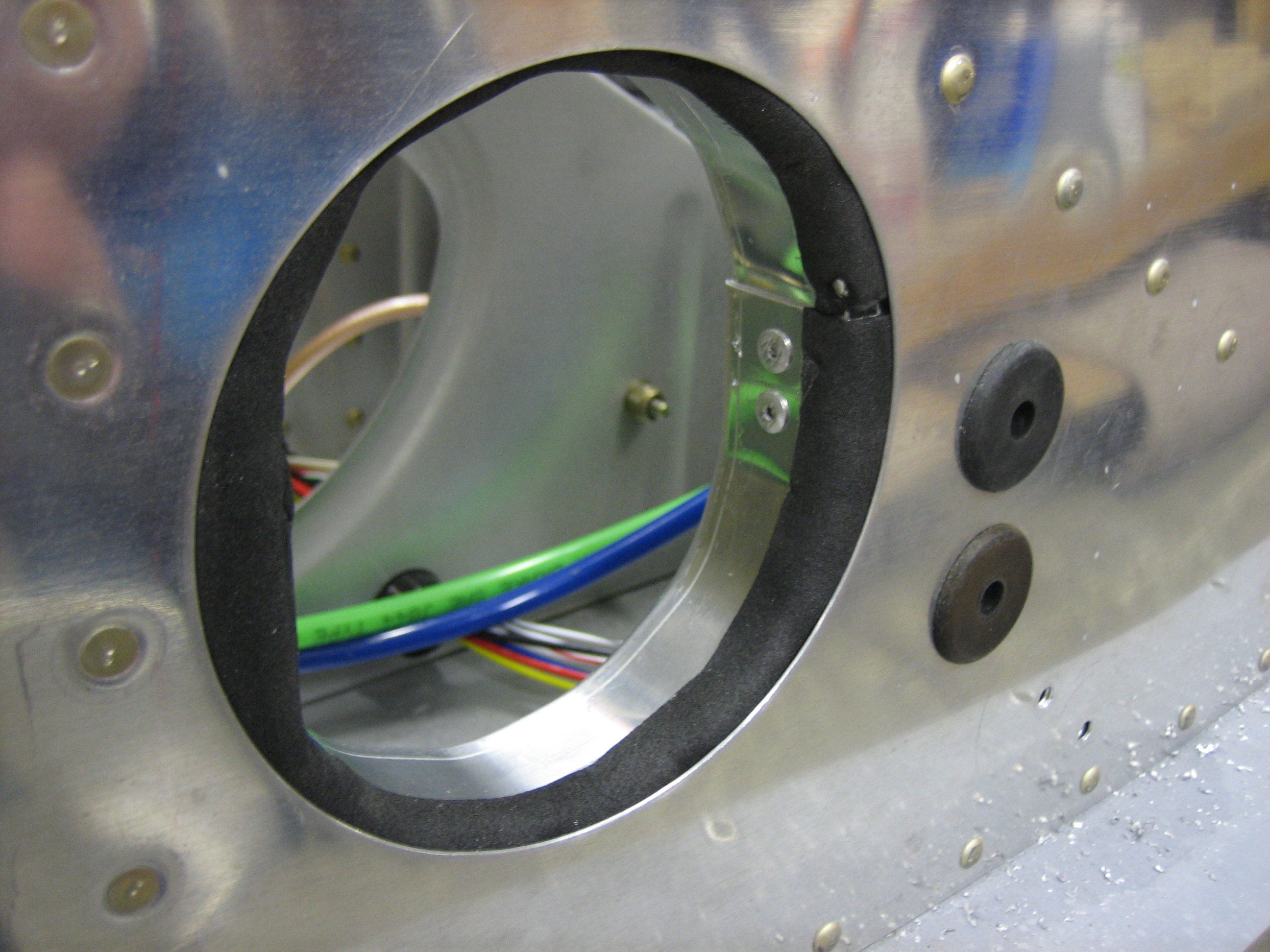
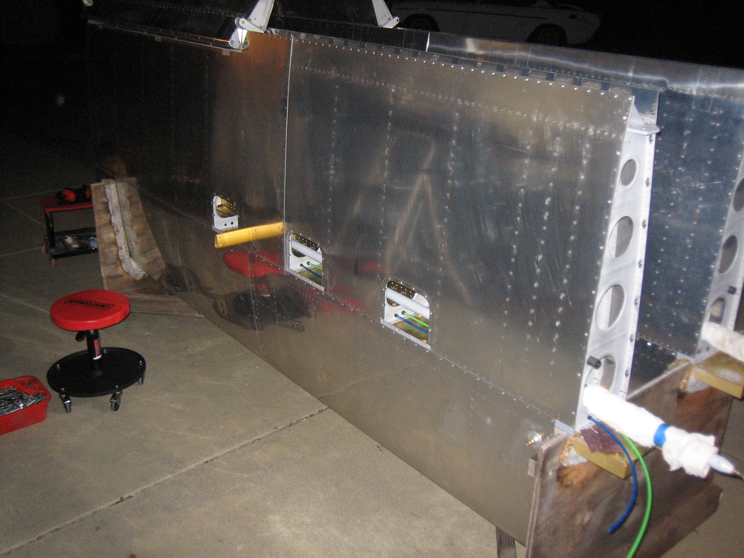
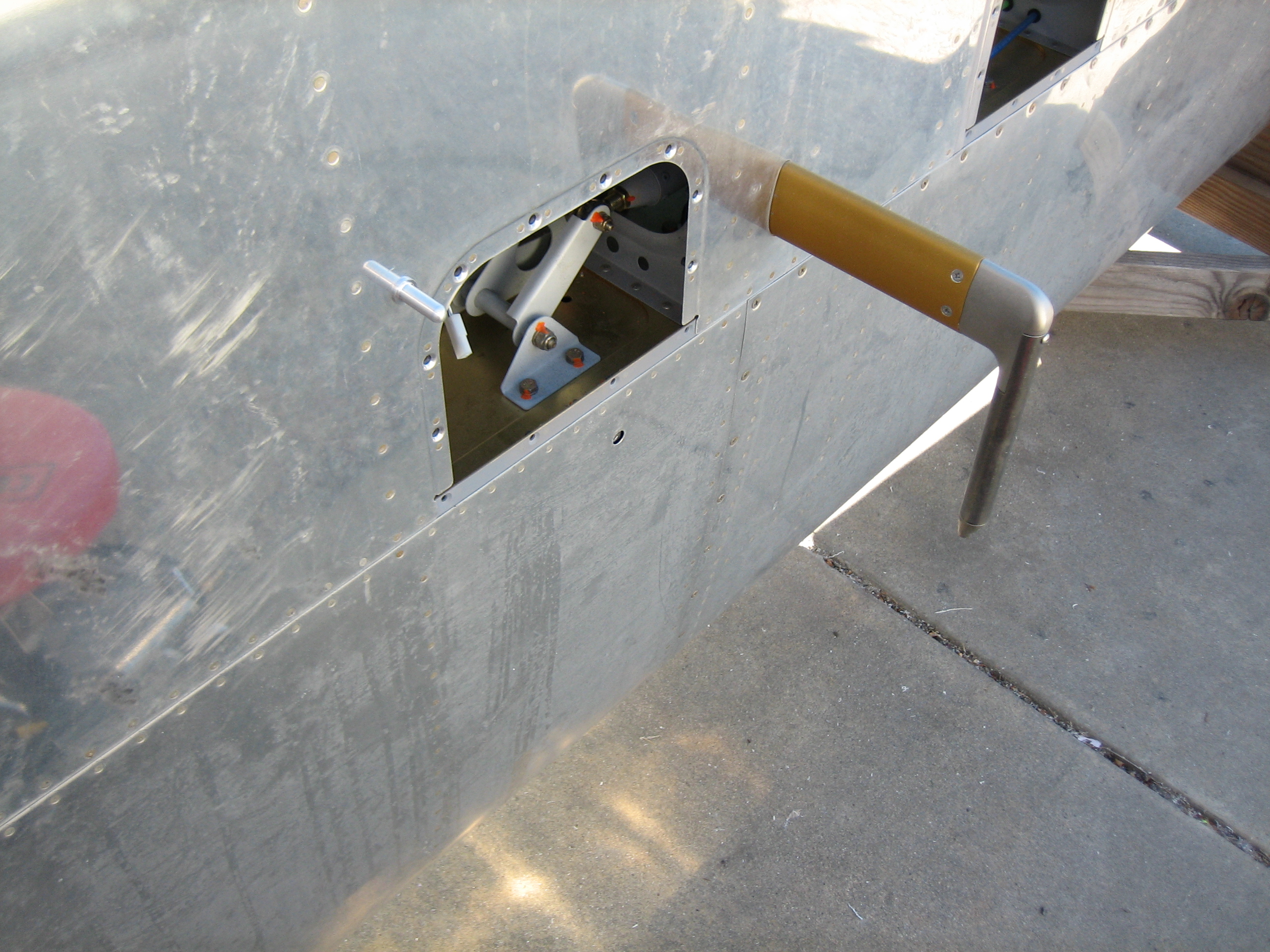
One of the biggest sources of air infiltration in the RV is the large hole in the side of the fuselage that allows the aileron pushrod to exit the fuselage. When flying at high altitudes, ice cold air comes in through this hole and then comes up through the seat belt attach holes, stick boot hole, etc. It also makes the seat pans really cold which can make sitting in the plane really uncomfortable. The solution to this is to install boots around the pushrods to block the air.
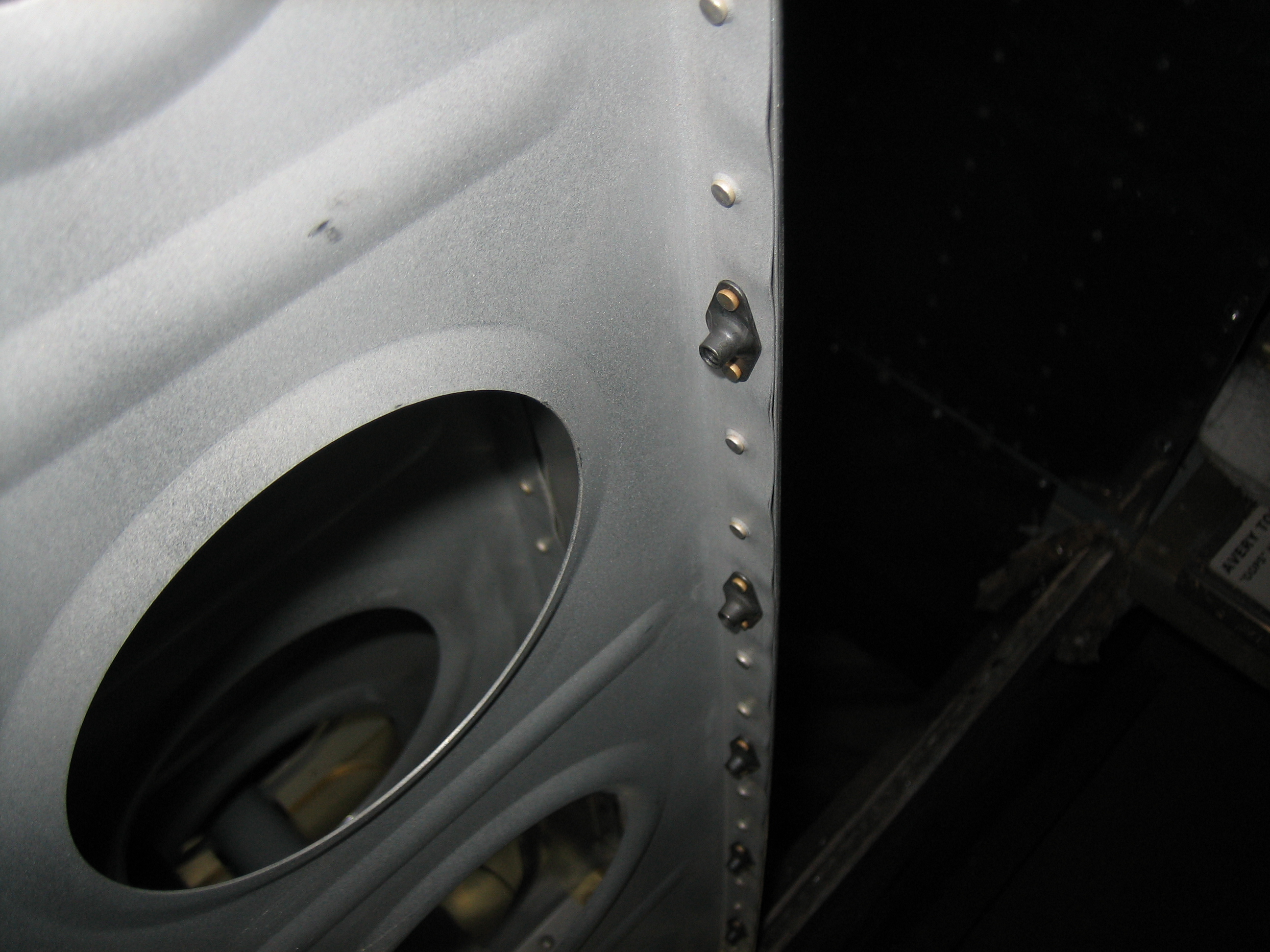
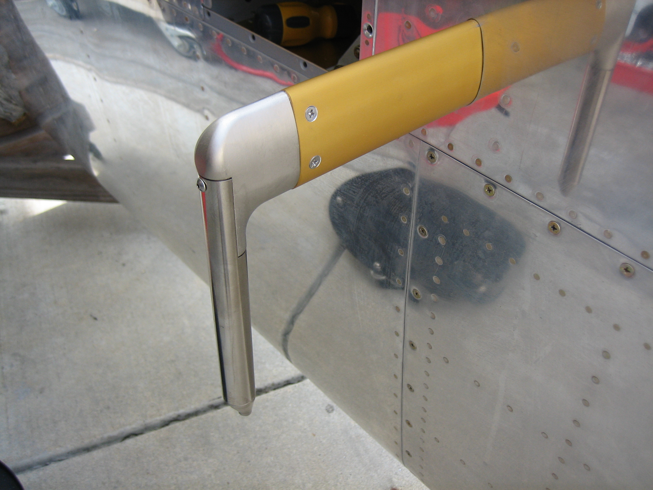
I installed the aileron pushrod boots from Classic Aero Design. These are more expensive than others on the market, but after installing them, I think the extra cost is absolutely worth it. These are very well designed and really easy to install. First up is to install the mounting ring. This is flexed into place so that the foam covered flange tucks between the outer fuselage skin and the adjacent rib. The ring is then expanded outward until the predrilled holes align. A couple of pop rivets anchors the rings in place.
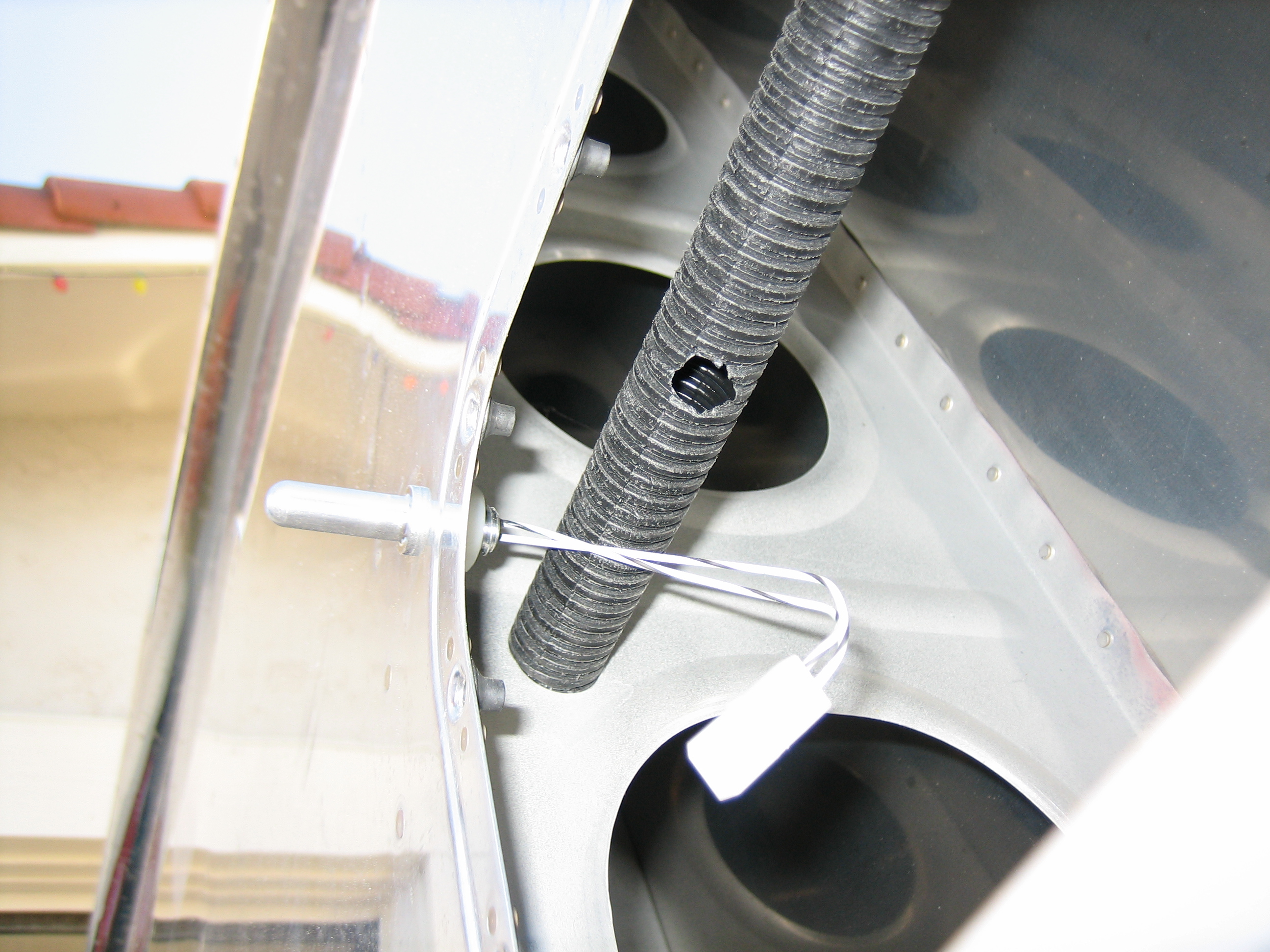
Next, a strip of adhesive backed foam is adhered to the outside of the flange. Notice that the inboard edge of the flange is bent outward slightly.
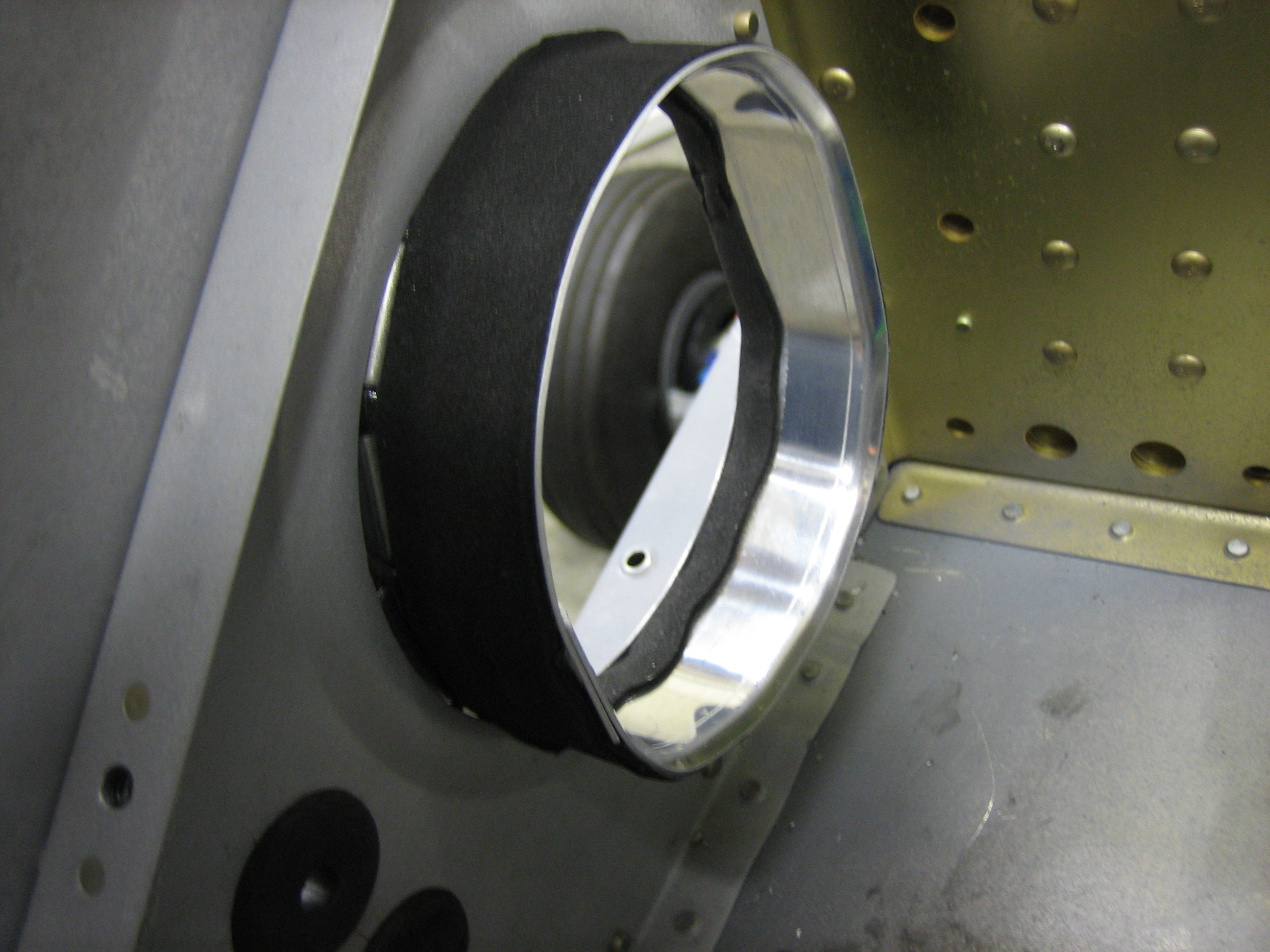
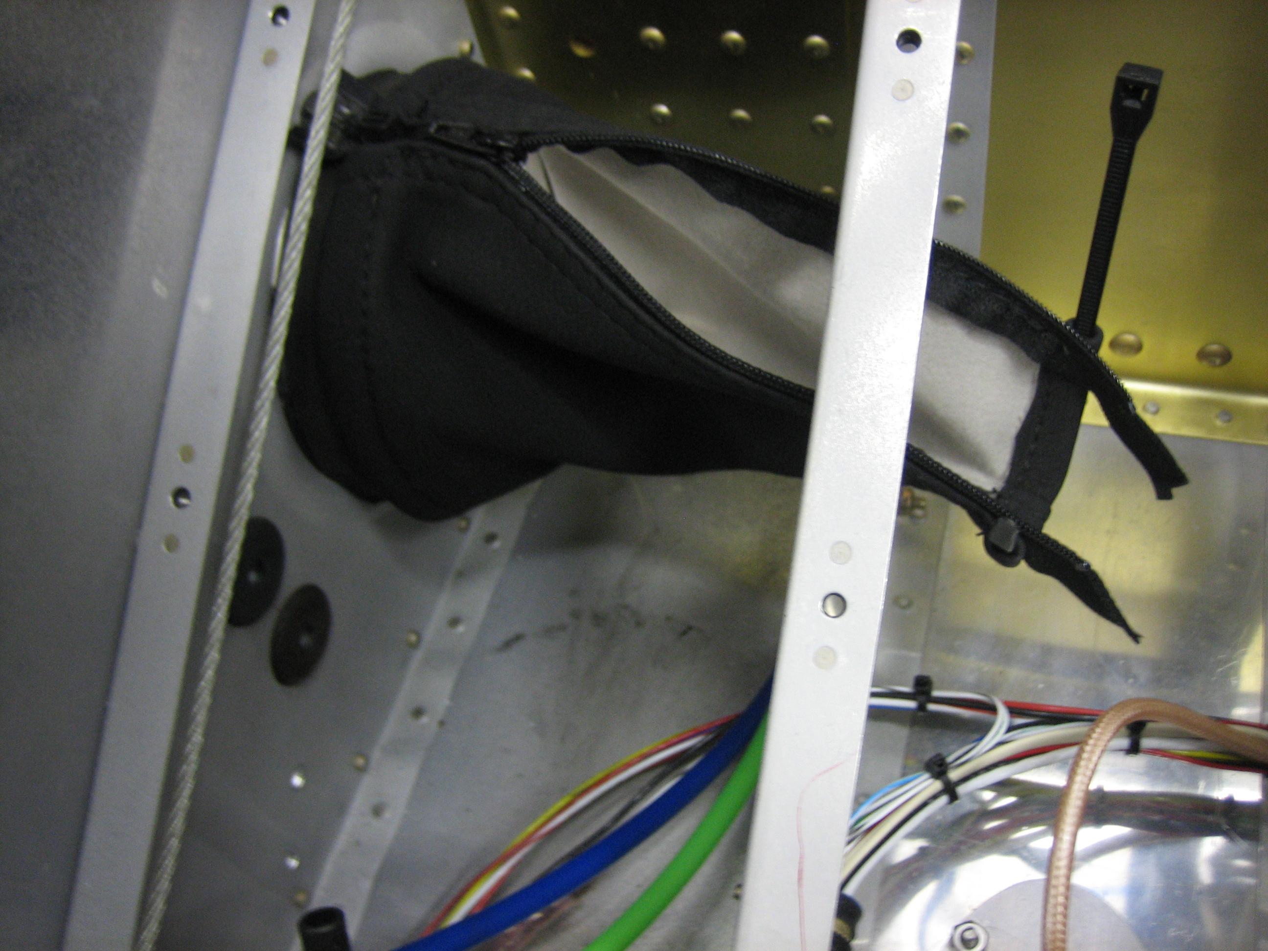
The boot is then installed over the flange and a zip-tie is used to cinch it down against the foam strip. The bent edge of the flange keeps the end from popping off the flange. Once the pushrod is installed for good, another foam strip will be adhered to the pushrod and the inner zip-tie will be used to anchor it.
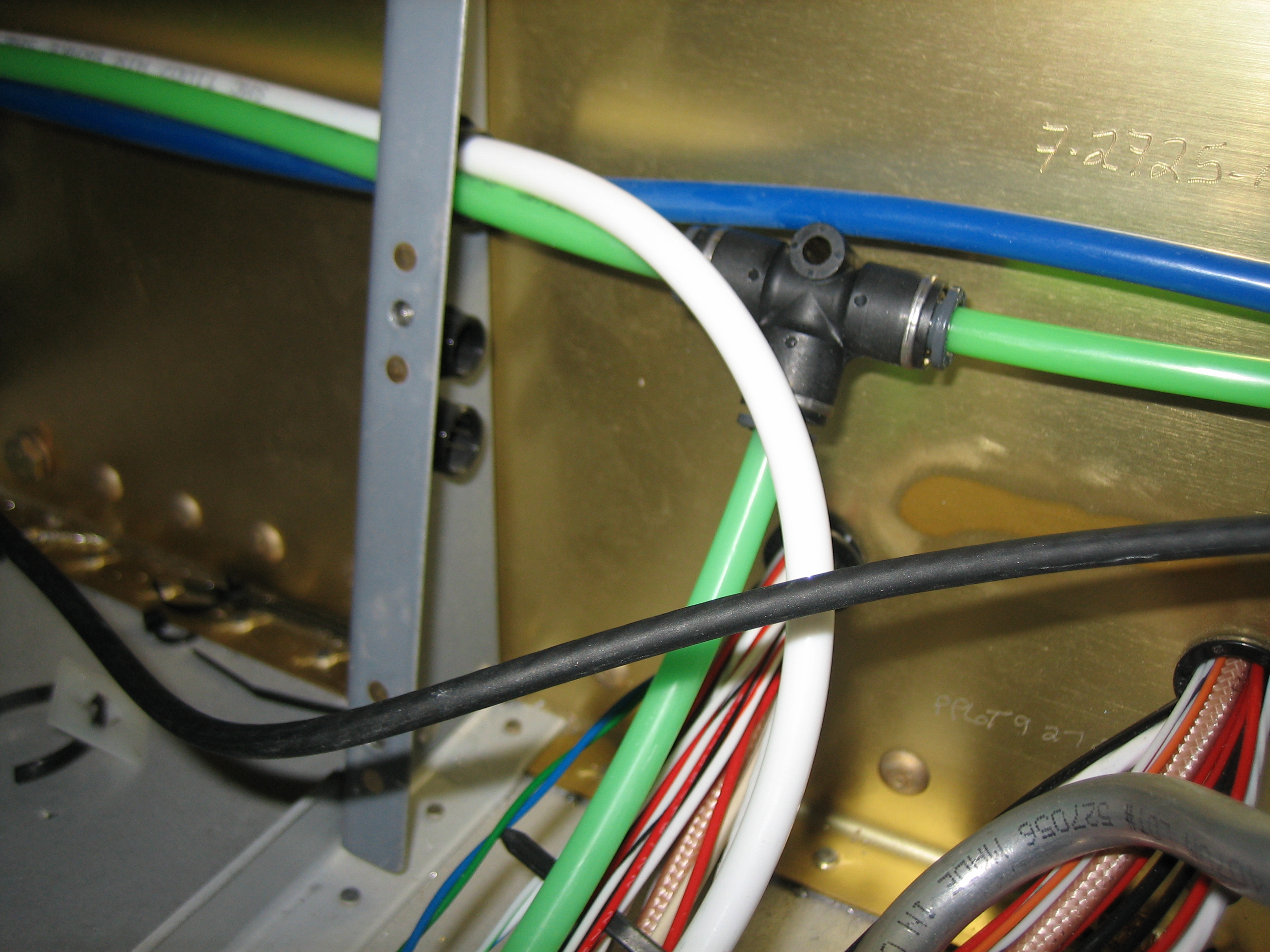
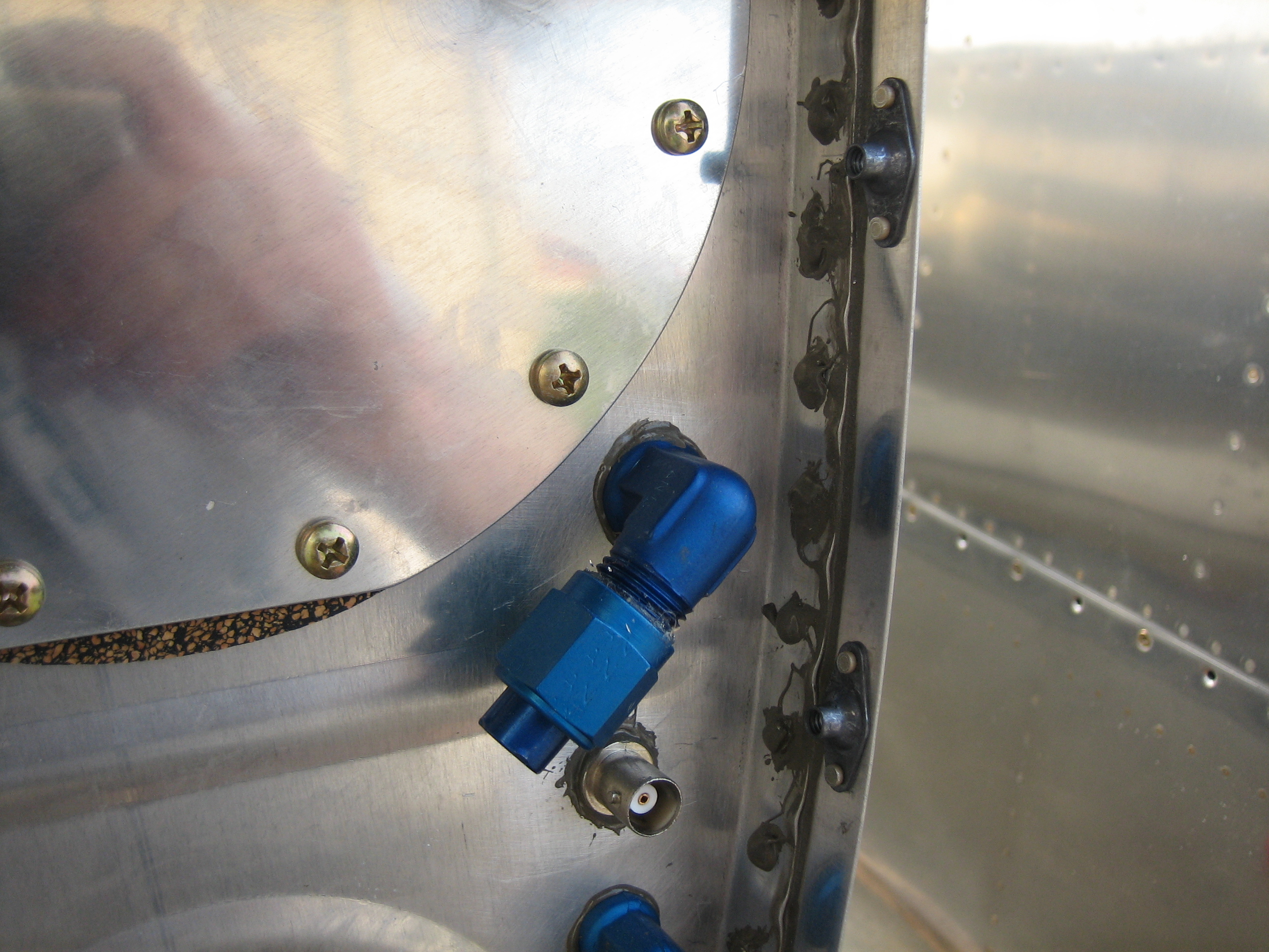
Finally, I tapped into the pitot tube to run a line up to the Gemini. I spoke with TruTrak yesterday, and the Gemini PFD has been delayed a couple of months, so they’re going to send me the Gemini ADI which has the exact same mounting holes and wiring/plumbing connections. Once the PFD is available, I’ll swap the ADI out for it.
Finished Skinning Wings
Andre stopped by again today (we both had the whole week off work) and helped me rivet the bottom skins on the left wing. We learned a few lessons on the right wing and were able to knock these out in only about five hours. The only thing that was a little more complicated on this wing was the pitot tube mount, but it wasn’t too bad.
Installed Pitot Tube and Nutplates on Tank and Root Ribs
I installed the pitot tube and connected the tubing inside the wing.
I installed the remaining nutplates on the root ribs and then propped the wing up on the leading edge of the tank. This looks precarious, but it is surprisingly stable.
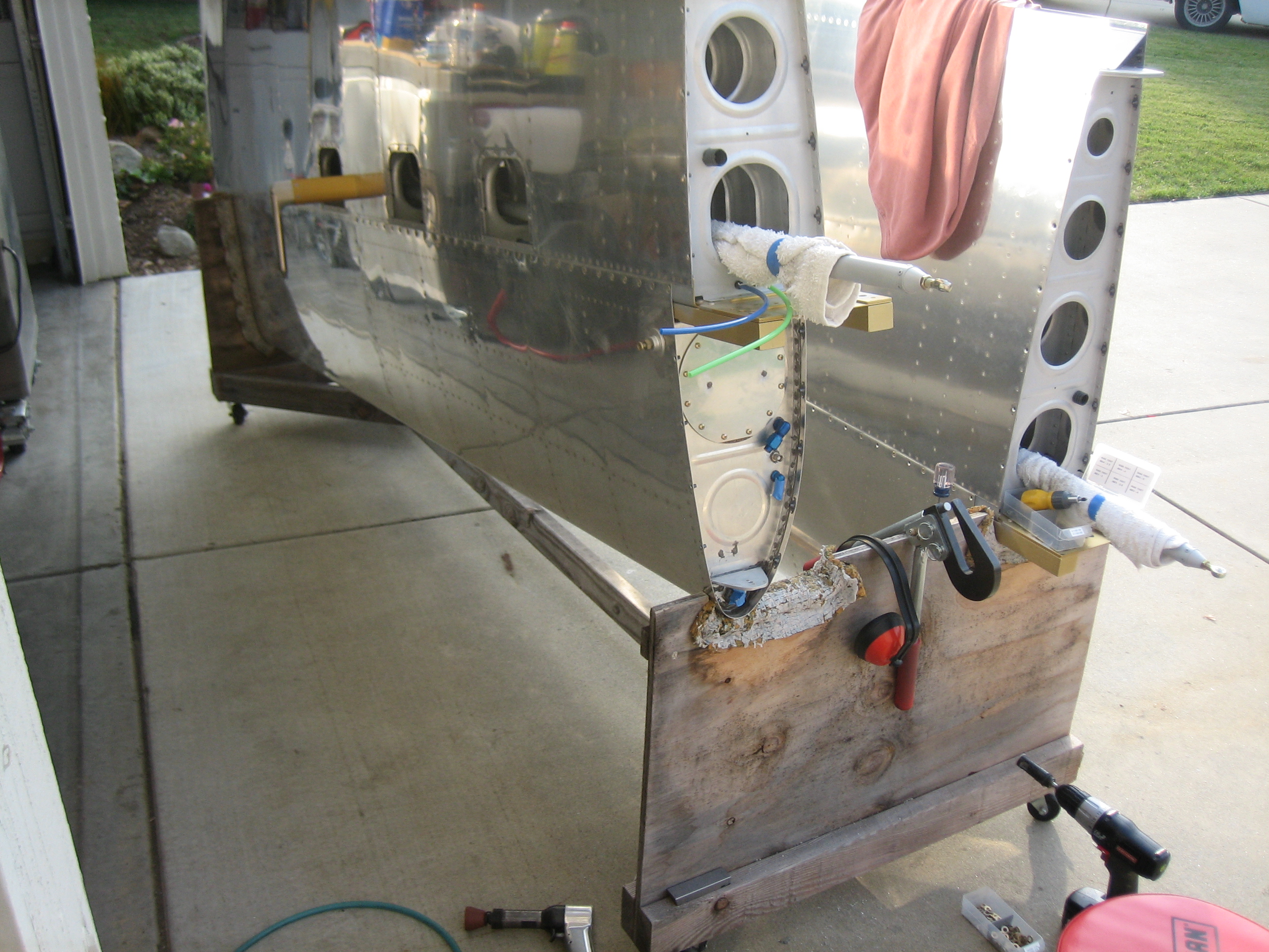
This allowed me to install all of the nut plates around the inboard edge of the tank skin…
…as well as install the tank attach bracket nutplates.
Finished Interior Lighting
I decided to finish up the interior lights tonight. The final light is a small stick-on LED light strip that will cast a dim glow in the footwell so that I can see where my feet are and see the fuel selector. I’m going to install it to the bottom of the control cable support bracket, but I need to paint it first, so it’s just held on with a piece of masking tape right now. I put a 39kΩ resistor inline with the lights to dim them down pretty far. The light should be dim enough that it’s not a distraction when flying at night.
OAT Probe and Empennage Fairings
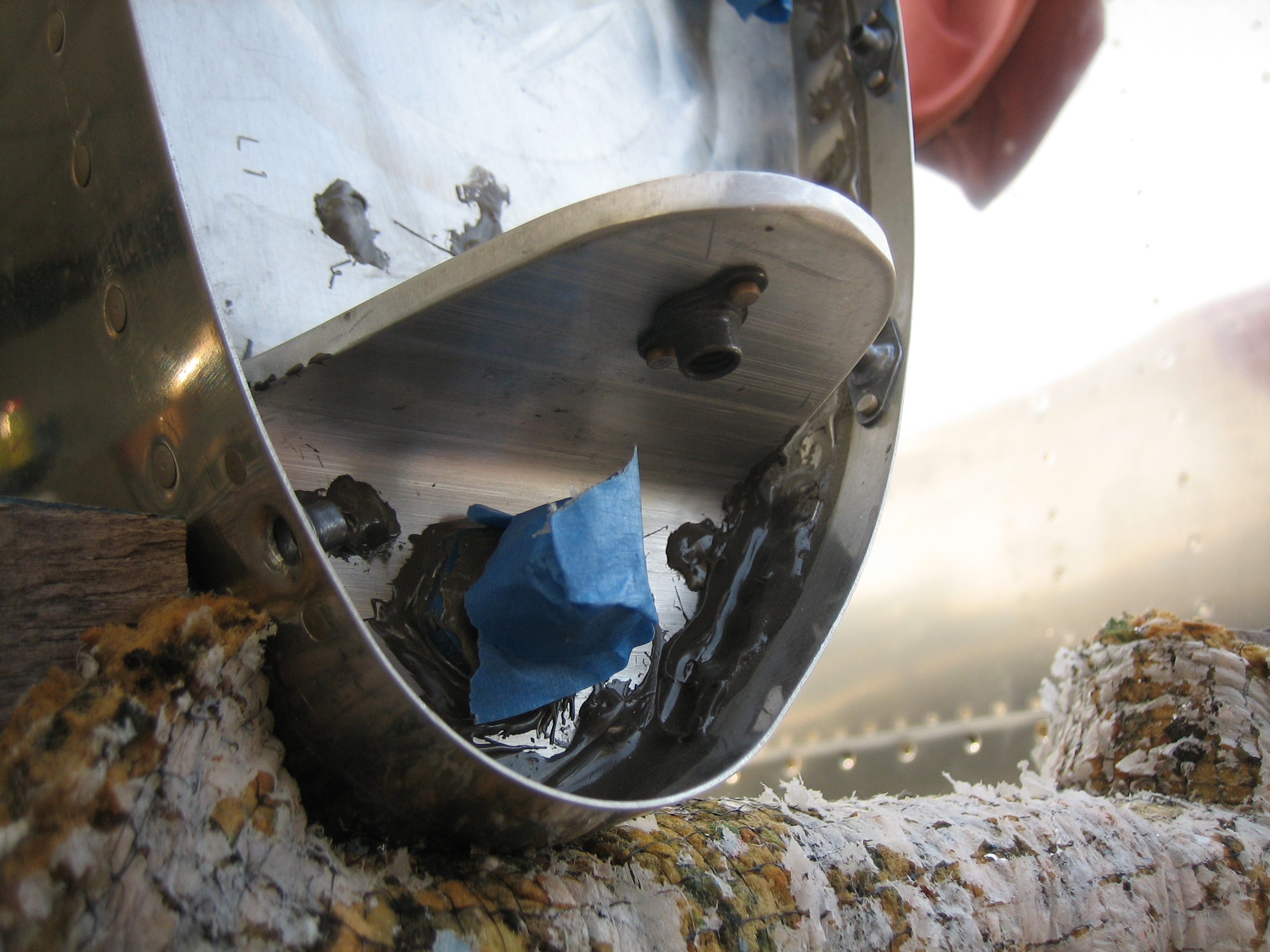
I drilled the bottom of the wing for the outside air temperature probe. I installed it in the wing, adjacent to one of the inspection plates (just to the upper left in this picture).
I also cut a small hole in the conduit here so that the OAT probe wires could exit. You can see the 2 conductor molex connector I used here as well. I’m honestly not sure the connector is worth the trouble since it would have to be cut off to remove the probe anyway. It’s probably better to just use a couple of butt splices to crimp the probe wires together with a service loop for future maintenance. With this done, I think I’m done with the wings until they go to the airport.
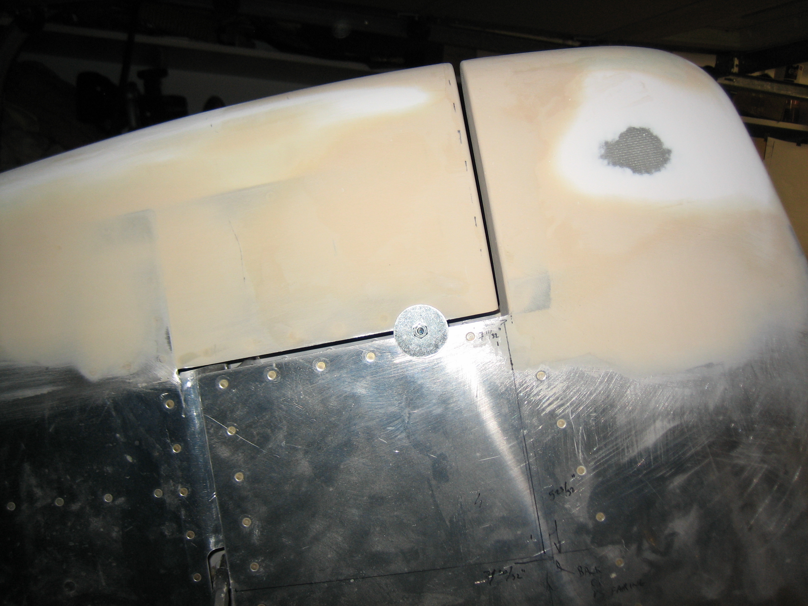
I needed a little more filler on the front of the rudder.
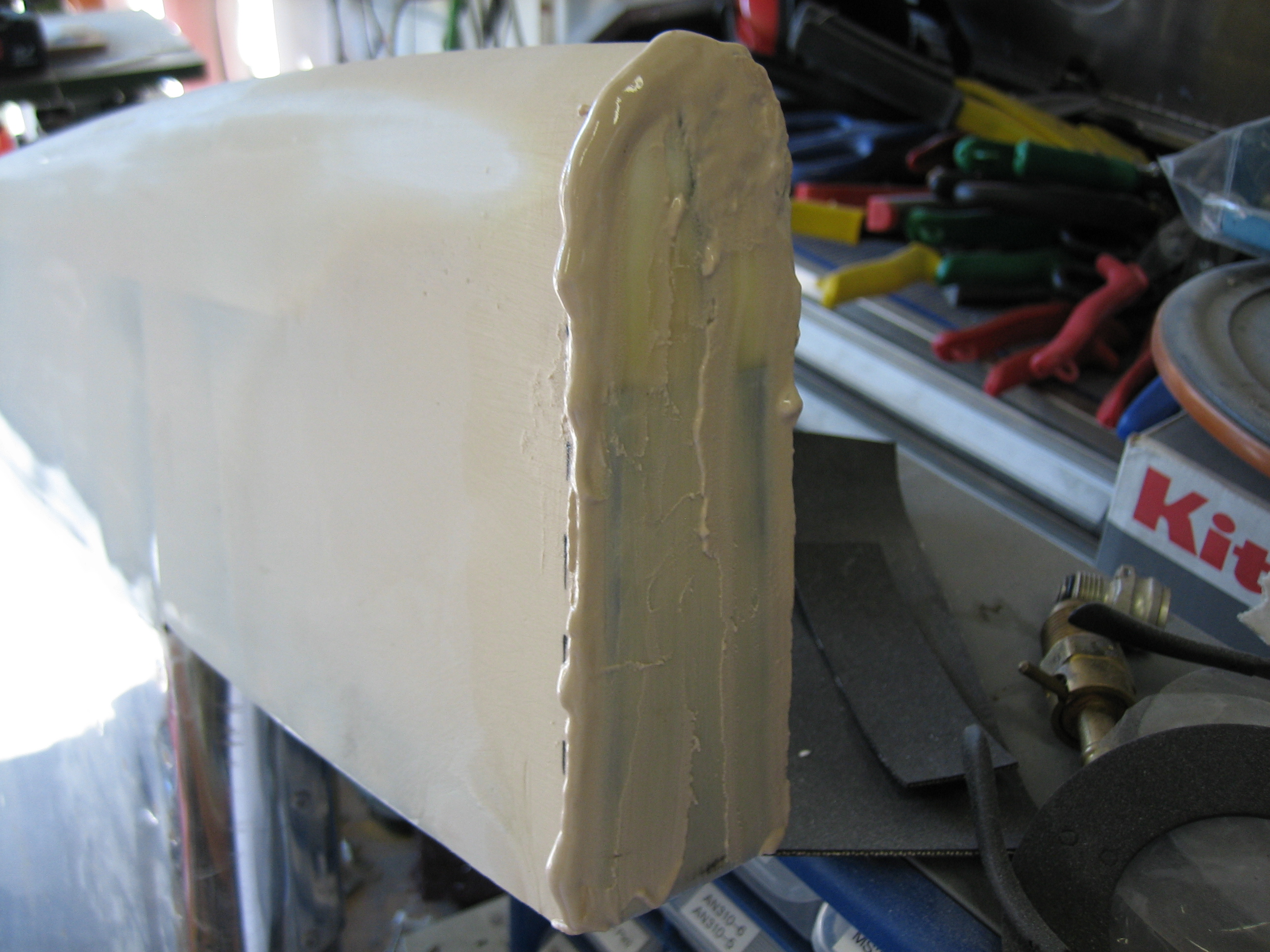
…as well as the aft side of the vertical stabilizer.
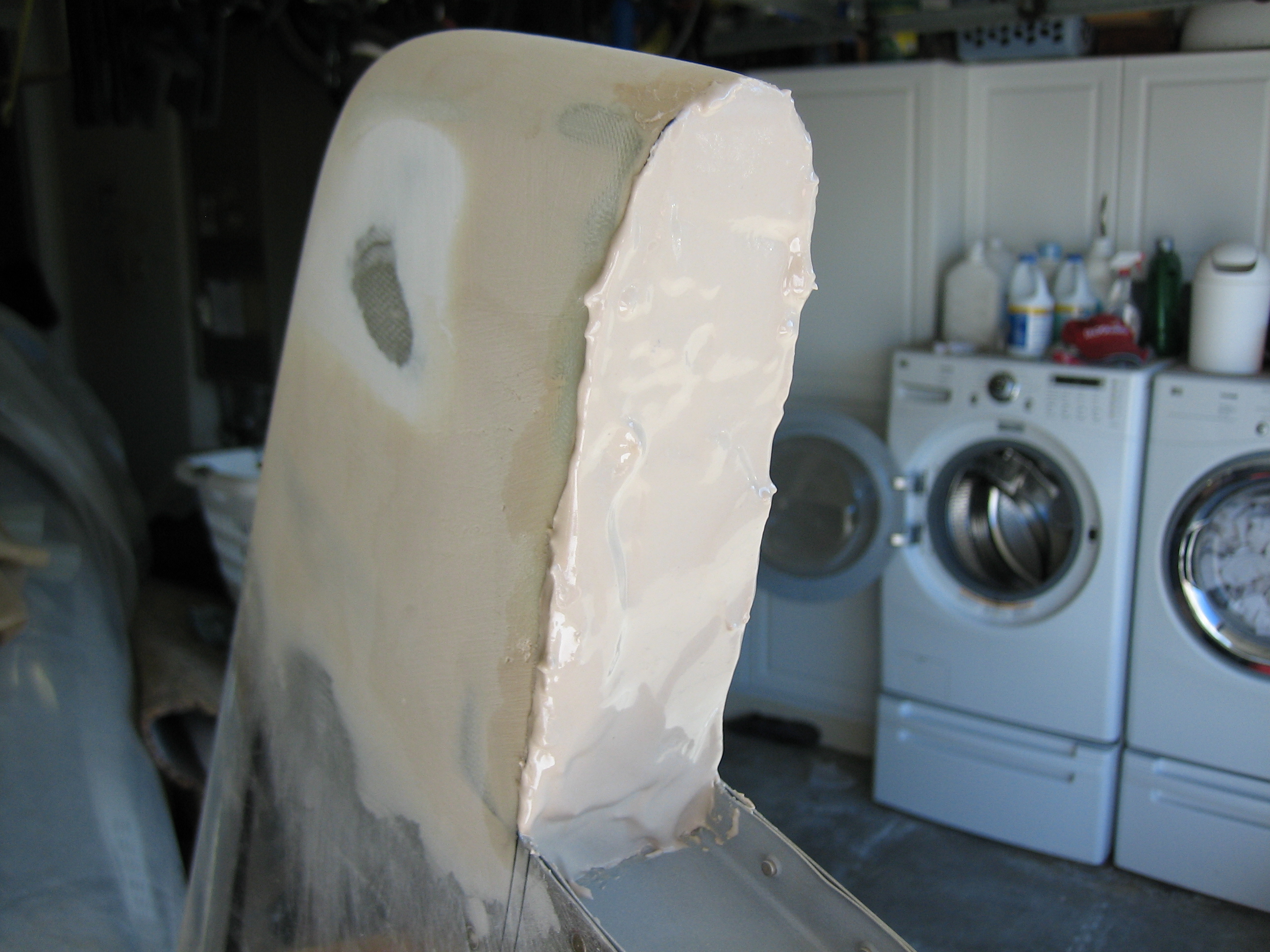
After that cured, I filed and sanded it down to create a uniform 0.150″ gap (the same as the lower gap under the rudder horn).
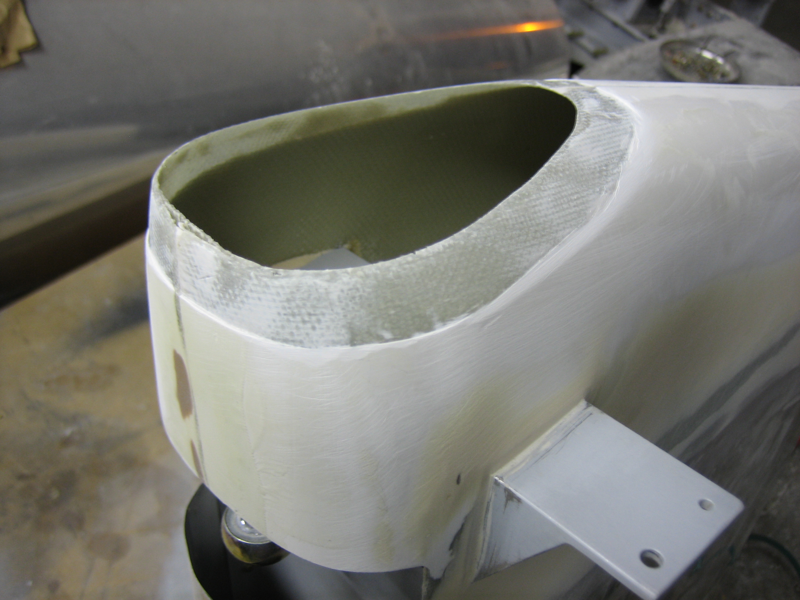
I also trimmed a little more off the bottom rudder fairing and then removed all of the gel coat around the hole in preparation for bonding a patch. For a non-structural patch like this, removing the gel coat isn’t necessary. I did it more so that the patch would be flush with the gel coat and I wouldn’t have to use as much filler to fair it in.
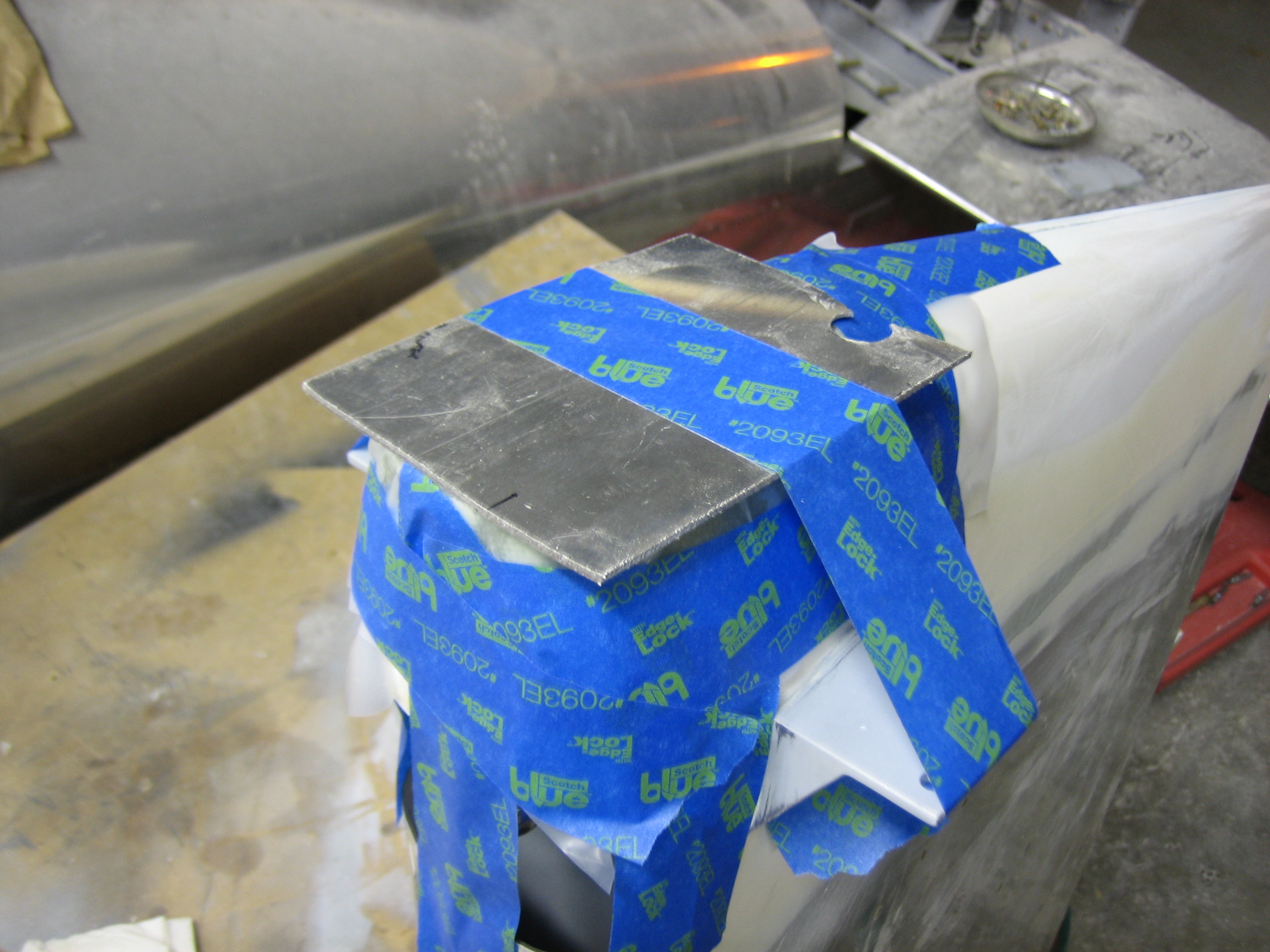
Finally, I added a patch made of three layers of 8.9oz/yd cloth.
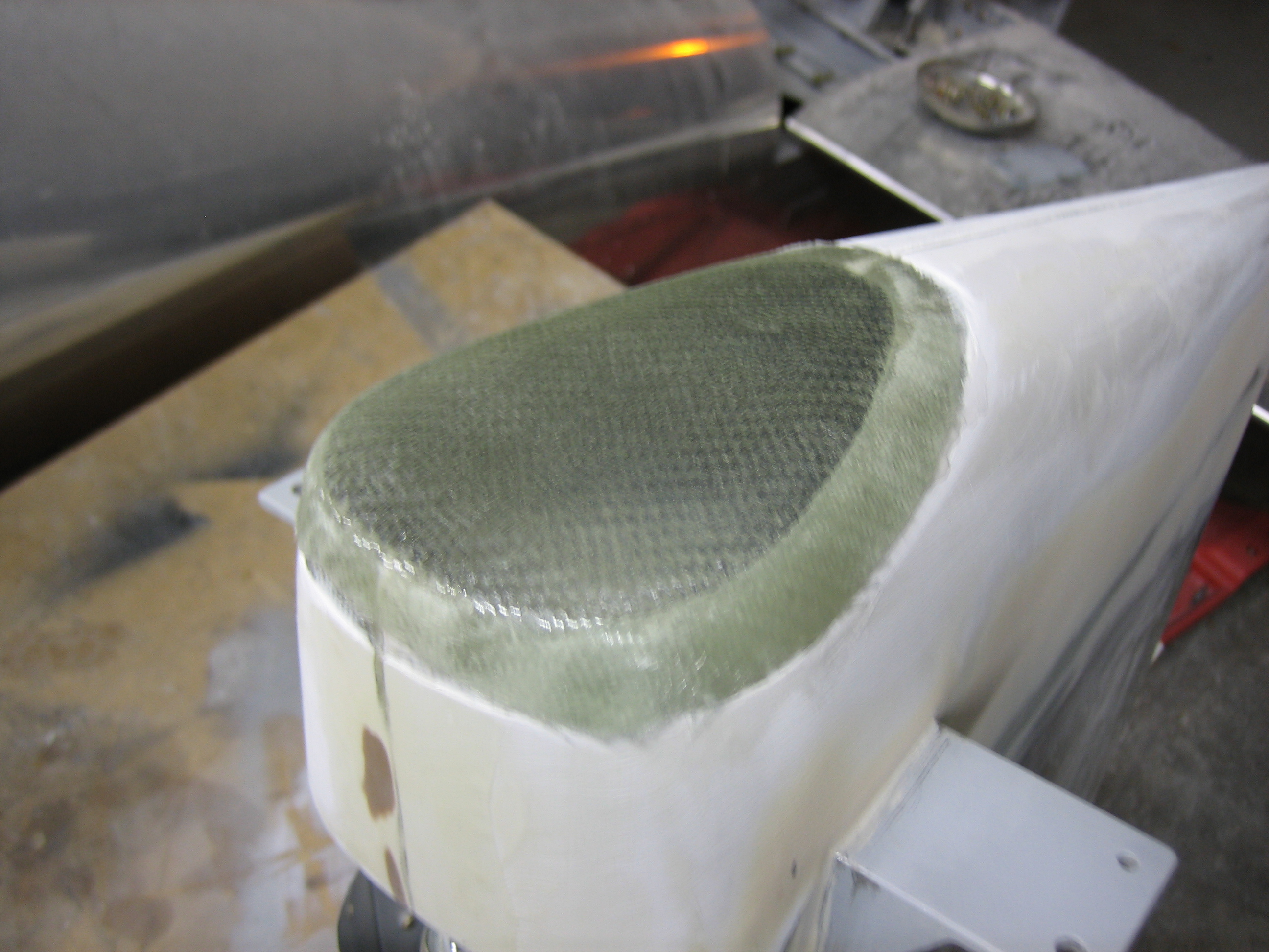
To keep it tight against the fairing, I laid a piece of plastic over the patch and taped it tight. I then taped a piece of scrap aluminum over the patch to ensure it cures totally flat.