Started Countersinking Cowl

I started countersinking the cowl for the rivets used to attach the hinges.  I was originally planning on using a permagrit countersink, but I tried my regular countersink and it did a great job.  I’ve heard it can dull them, but buying a new one would be cheaper than a permagrit countersink so I don’t think it’s worth it.

Worked on Cowl Attachment and Dynon GPS Antenna Mount

Now that I know where the side hinges will rivet to the firewall, I riveted the sides of the firewall flange above that point.

Then riveted the hinges on below that.  The bottom seven rivets can’t be reached with the squeezer, so I’m going to have to shoot and buck them somehow.

I’ve been planning on mounting the Dynon GPS antenna under the cowl.  Most builders fabricate a little shelf that runs between the engine mount and the firewall, but that would get in the way when changing the oil.  Since I only have one antenna to mount, I decided to fabricate a small mount that will attach directly to the engine mount.  I placed the straightedge between the top of the firewall and the spinner to see how high I can go.  The actual cowl in convex through here and will actually provide more clearance than this.

The mount is just a short piece of Z channel that I trimmed to fit the antenna.  I’ll drill a couple of holes in the bottom flange and attach it to the engine mount with a couple of adel clamps.

Installed Throttle Cable Bracket

For some reason, I decided to install the throttle cable bracket tonight.  I fabricated this bracket months ago, but it needed to be powder coated before it could be installed.  I sprayed a couple of coats of white powder coat on it and baked it for awhile in my toaster oven.

I then drilled the heads of a couple of coarse thread AN4 bolts and installed the bracket to the boss on the front right of the engine.  It was a little tight getting the safety wire installed, but I managed to get it done on the first try.

I’m not sure why I took this picture, but here’s a shot of the other side.

Ordered Avionics Stack

I ordered my avionics stack today.  I’m going with a PS Engineering PMA8000BT audio panel and Garmin GTN 635.  I went back and forth about both units a bit.  I was originally going to install the PMA5000EX audio panel, but ended up deciding the Bluetooth functionality would be worth it for making phone calls and listening to music.  I was also originally planning on installing the GTN 650, but ultimately didn’t think I would use the VOR/Loc/Glideslope functionality much.  Switching to the 635 not only saved me about $1,000, but the unit is 0.8 lbs lighter and I probably saved another several pounds of antennas and wiring (not to mention hours of time that I would have spent hooking up the additional antennas).

Tidied Up Wiring

I spent a little time tonight tidying up some wiring runs under the seats.  I installed an adel clamp on the wires to the left of the center tunnel.  I haven’t tightened either of these down fully yet since I want to wait until the GPS antenna cable is adjusted to length and I still need to run the wires for the control sticks.

I installed the adel clamp supporting the wires coming out of the left conduit and added a couple of zip-ties to tie everything together.  It’s amazing how solid these wire bundles become when zip-tied together.

I added an adel clamp to keep the pitot/AOA lines held down to avoid interfering with the aileron push tube.  I might have been able to use a zip-tie base attached with a pop-rivet, but I really don’t want there to be any possibility of anything coming loose around the flight controls.  You can also see at the top of this picture that I took all of the snap bushings out of the forward holes in each seat rib.  I have no idea why Van’s has you drill holes here.  It’s a really poor place to put them since they’d have to snake around the control stick brackets.

I also tidied up the wiring aft of the baggage bulkhead.  Everything is firmly secured and well supported.

Installed Garmin GTN 635 Antenna

I stopped by my avionics shop over lunch today and picked up the GA 35 antenna for my GTN 635.  Dynon recommends installing any GPS antennas at least 1′ from the ADAHRS, and Garmin recommends installing the GPS antenna with at least 7.5″ ground plane all the way around the antenna.  These two recommendations necessitated moving the antenna behind the F-707 bulkhead.  I fabricated a doubler from 0.040″ aluminum that matches the outline of the antenna and then installed it to the fuselage.

Here’s where the antenna is relative to the aft window.  The ADAHRS is roughly under the aft edge of that piece of paper, putting it roughly 18″ from the GPS antenna.

Afterward, I crimped on a TNC connector and ran the antenna cable along the underside of the upper rib next to the Dynon network cable.

Tidied Up Firewall Forward Wiring

I got an order from McMaster Carr that included some more silicone adel clamps along with some tefzel zip-ties.  I installed a few to secure all of the wires near the right firewall pass-through.

This nicely tidied up the EGT, CHT, and Lightspeed Ignition wires running across the upper engine mount tube.

I also replaced a bunch of the temporary nylon zip-ties with the tefzel.  Regular nylon zip-ties are only good up to about 185º F.  Black, UV stabilized zip-ties are better at up to 221º F, but tefzel is good up to 300º F.  There are even higher rated zip-ties such as PEEK which is good to 500º F, but they’re over $3 per zip-tie!  All of the wire insulation in the plane is also tefzel insulated, so if it’s hot enough that these zip-ties melt, I’ll have other problems.

I also finished up the Dynon GPS mounting bracket.  I put a gentle radius in the lower flange to follow the curve of the engine mount and drilled a few lightening holes.  I then primed and painted it gloss white.

Installed GPS Mount and Started Instrument Panel

With the mounting bracket painted, I installed it on the engine mount.

The EGT and CHT wires from cylinders 1 and 3 run under the bracket and pick up the GPS wires.

There is still plenty of access to the back of the engine for oil changes and maintenance.  I like this approach so much better than the shelf that many builders go with.

I then finished up securing the wires along the top left engine mount tube.  This bundle picks up the oil temperature sensor, manifold pressure sensor, oil pressure sensor and fuel pressure sensor wires along the way.

I’ve been working on my panel layout on and off for many months.  I’m happy with it now, so I started transferring it to the panel this afternoon.  You can’t see much here, but my computer model was perfect.  Everything fits exactly as it should with the clearances I determined in the computer.

Here’s a rendering of the panel from the modeling software.  The only thing not pictured here is the hobbs meter.

Resumed Work on Baffles

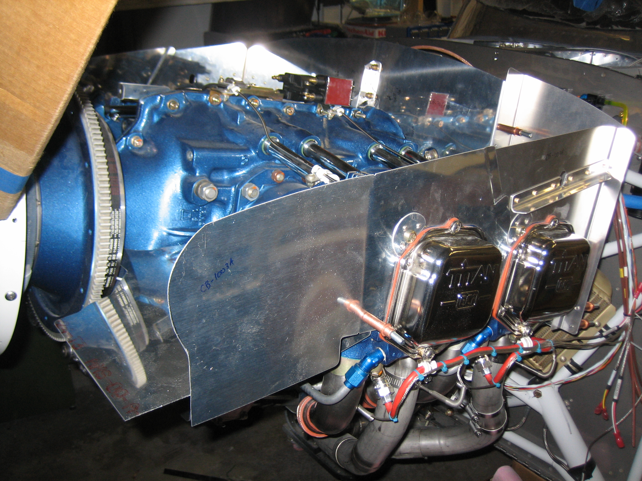
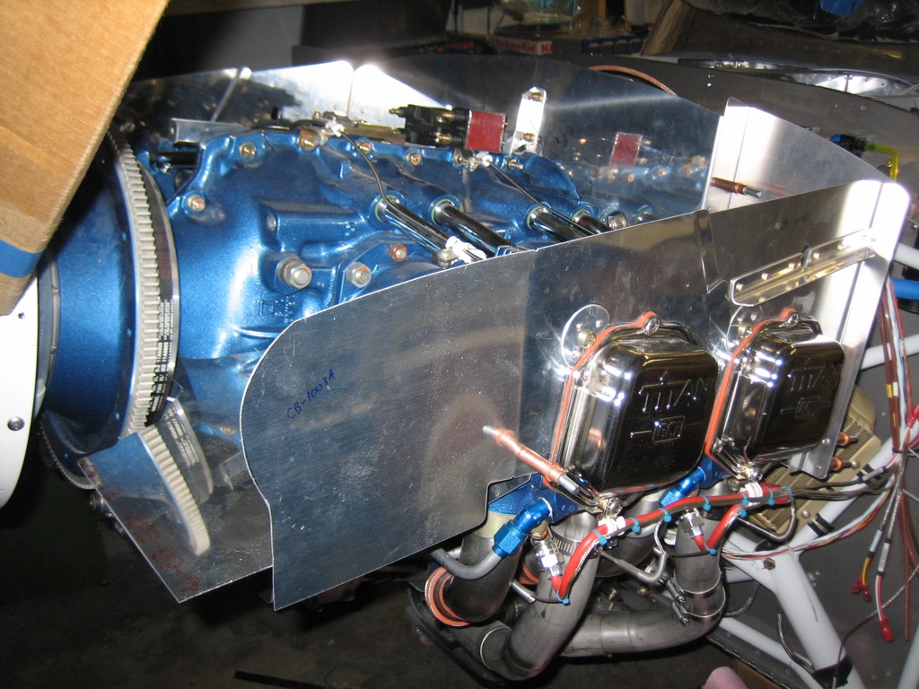
With the cowling fit, I resumed work on the baffles.  After a little trimming where the baffles fit around the rocker arm covers, I got everything mounted to the engine except for the part behind the spinner.

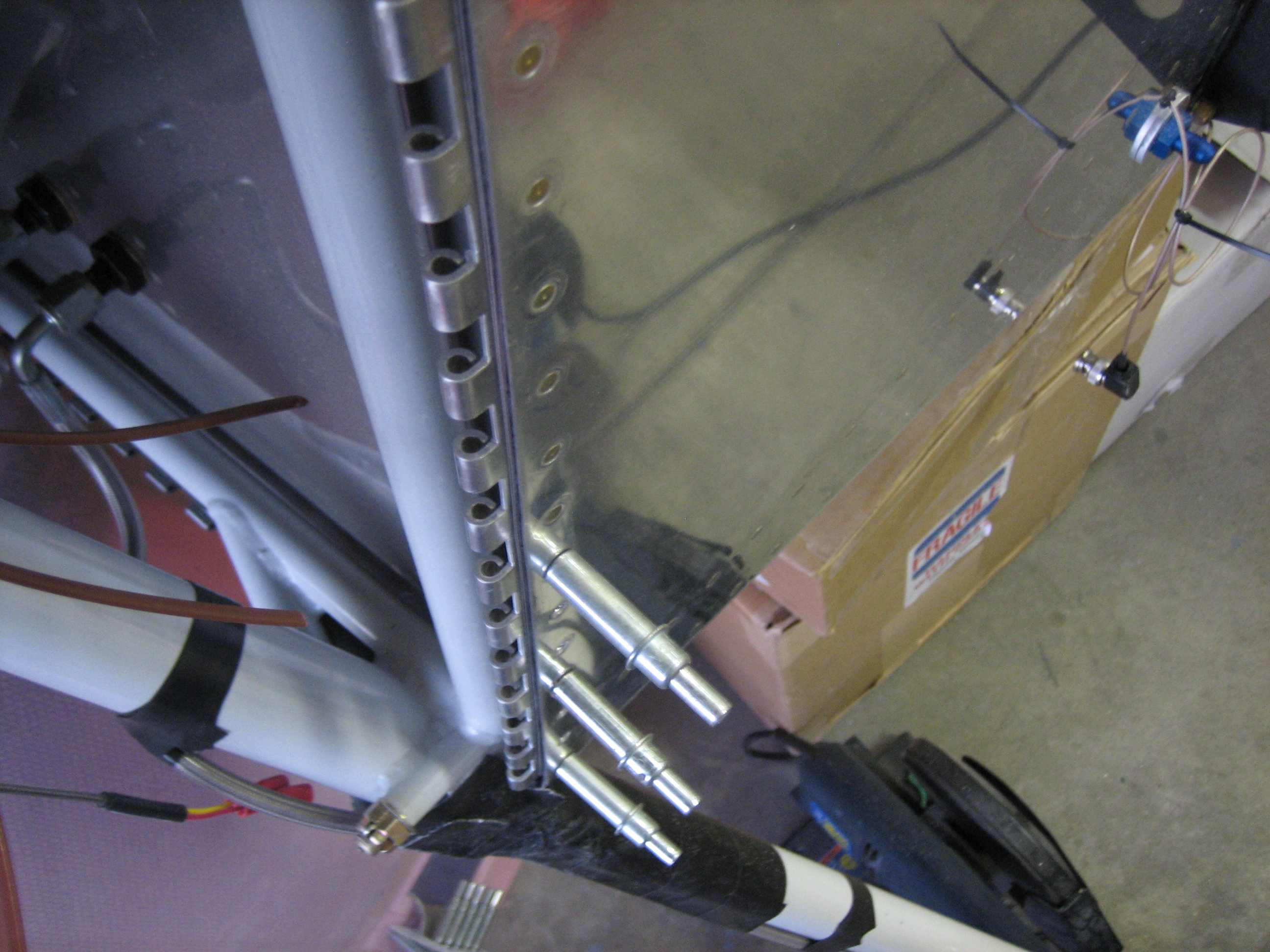
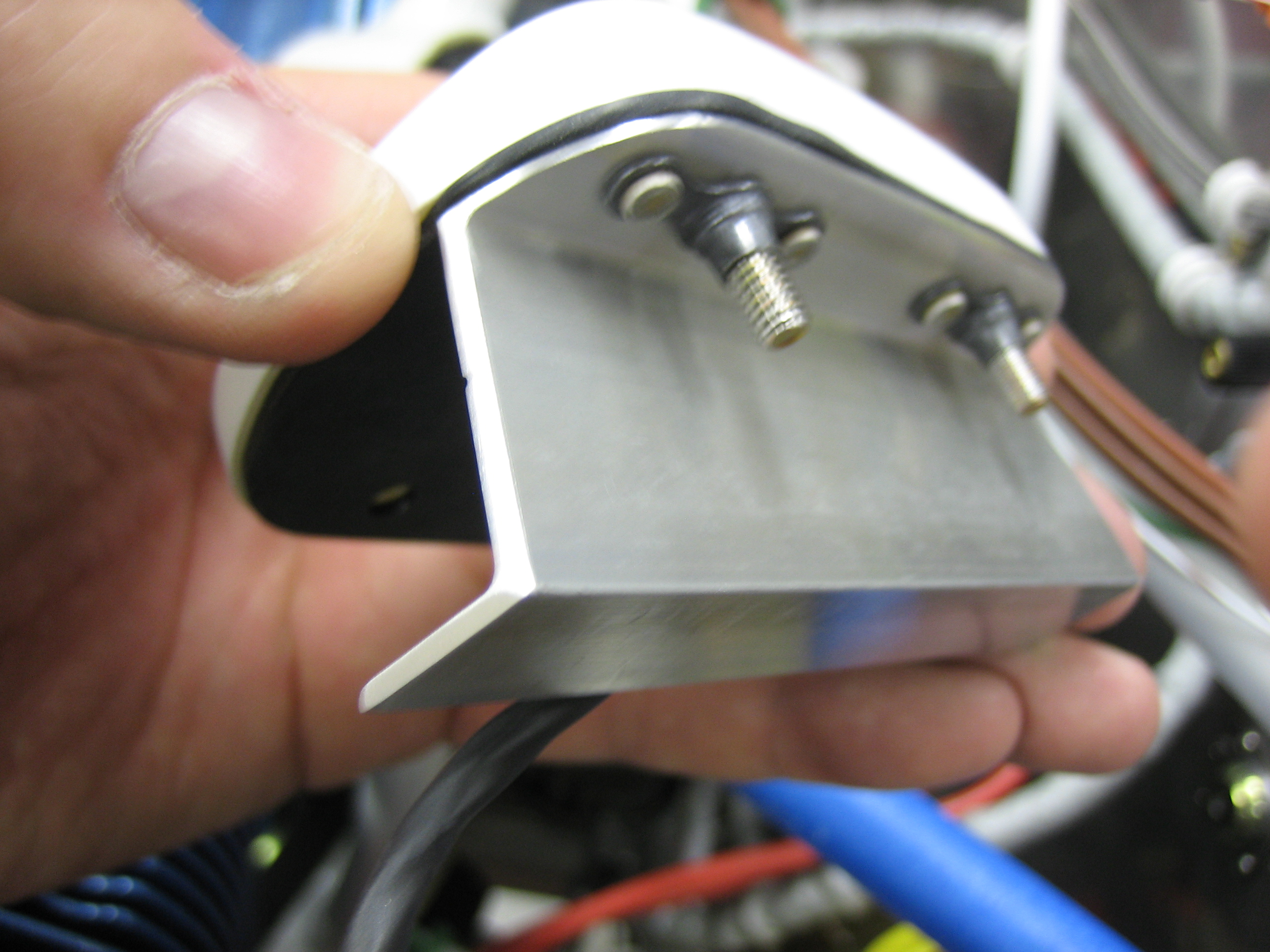
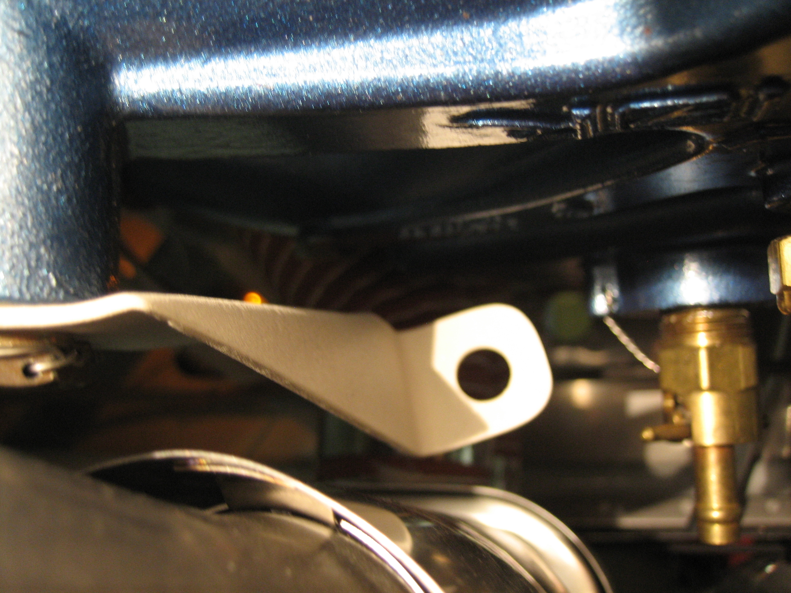
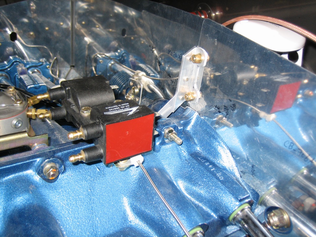
I had previously cut off the flange from the aft baffle support since it pushed the aft baffle walls too far back.  I fabricated I replacement from some 1/16″ angle stock and riveted it to the baffle support.

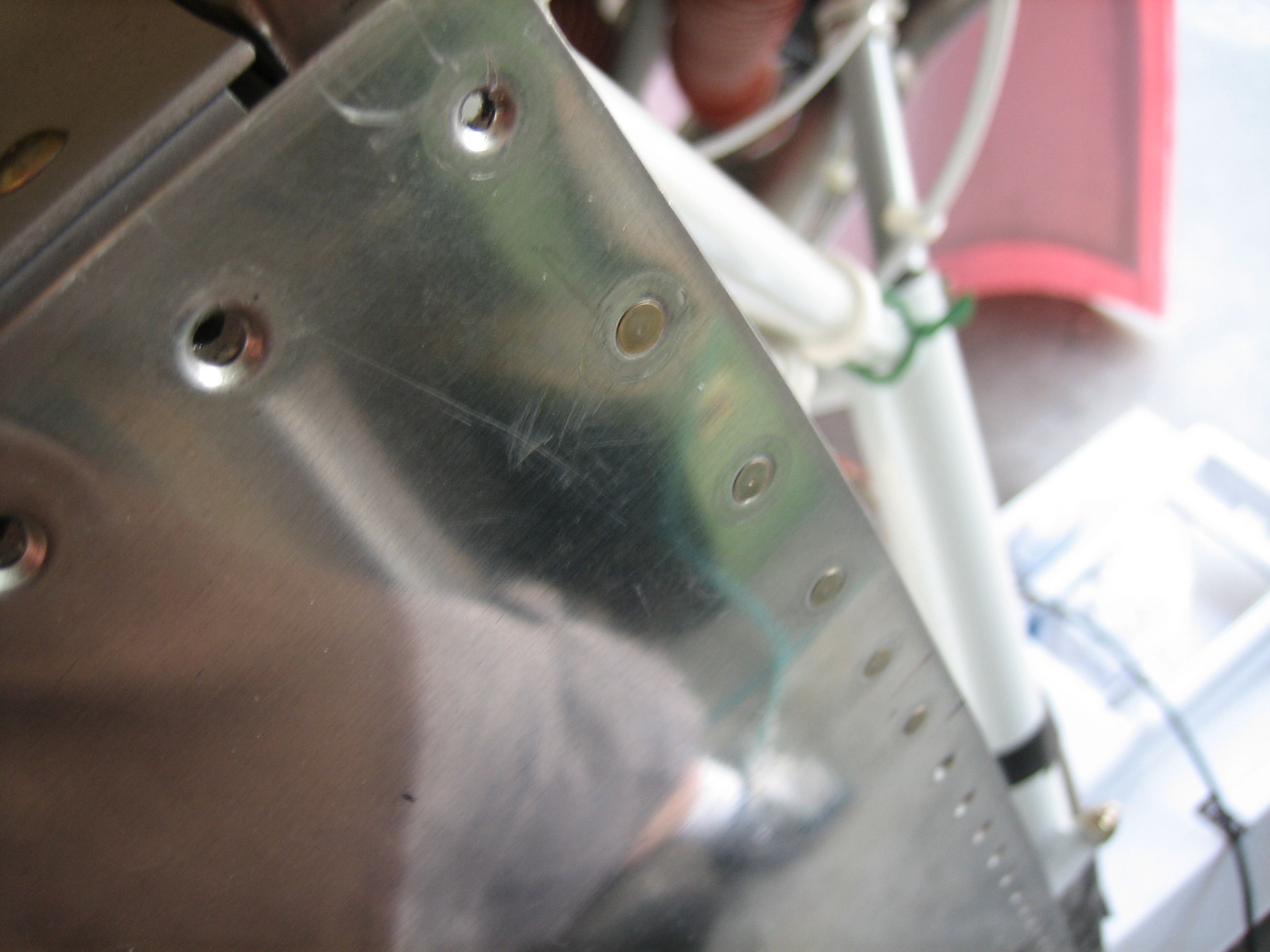
To ensure the aft wall is in the right spot, I clamped a straightedge across it.  I then clamped the bracket to the wall and drilled the holes.

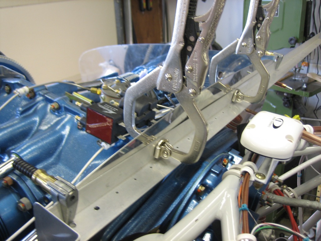
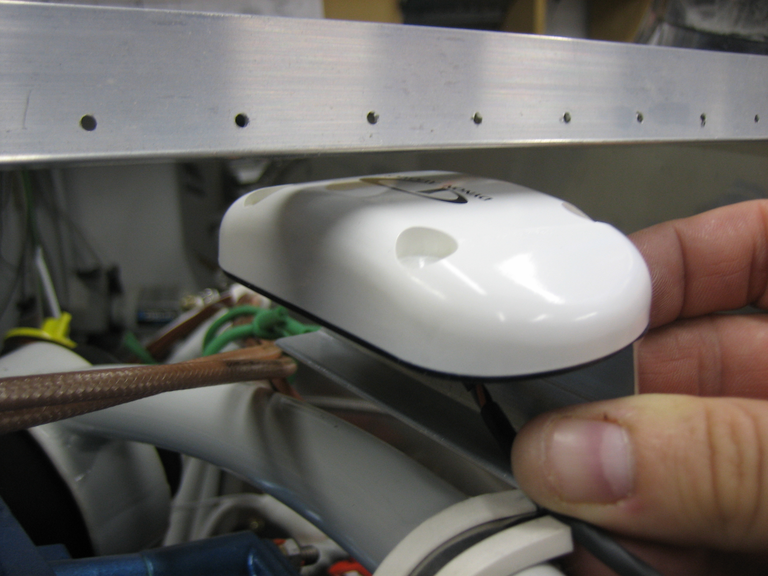
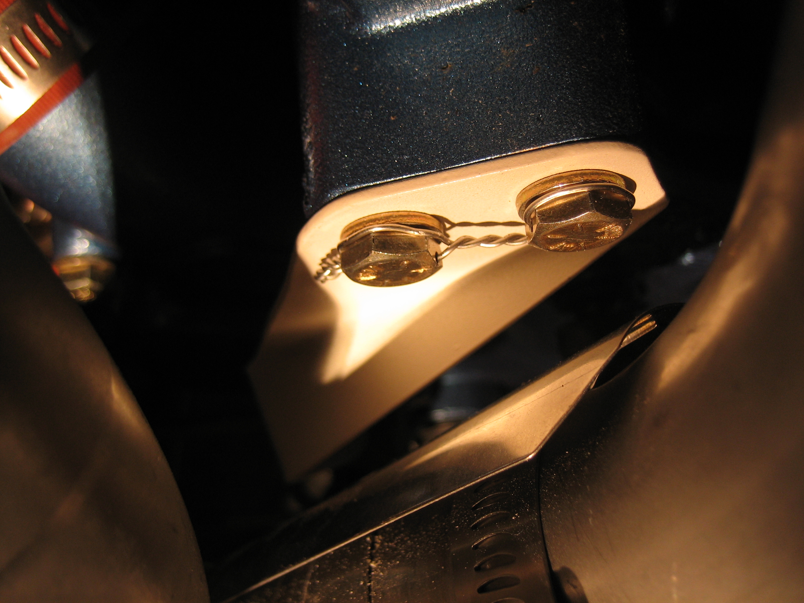
With the aft baffle wall bolted to the support, the back wall becomes very rigid.

I made the preliminary angled cuts on the ramps and made the necessary bends in the forward side baffles.

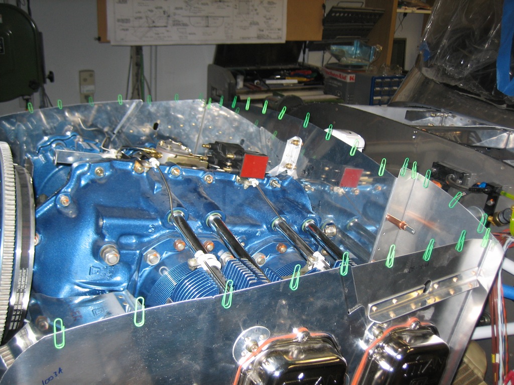
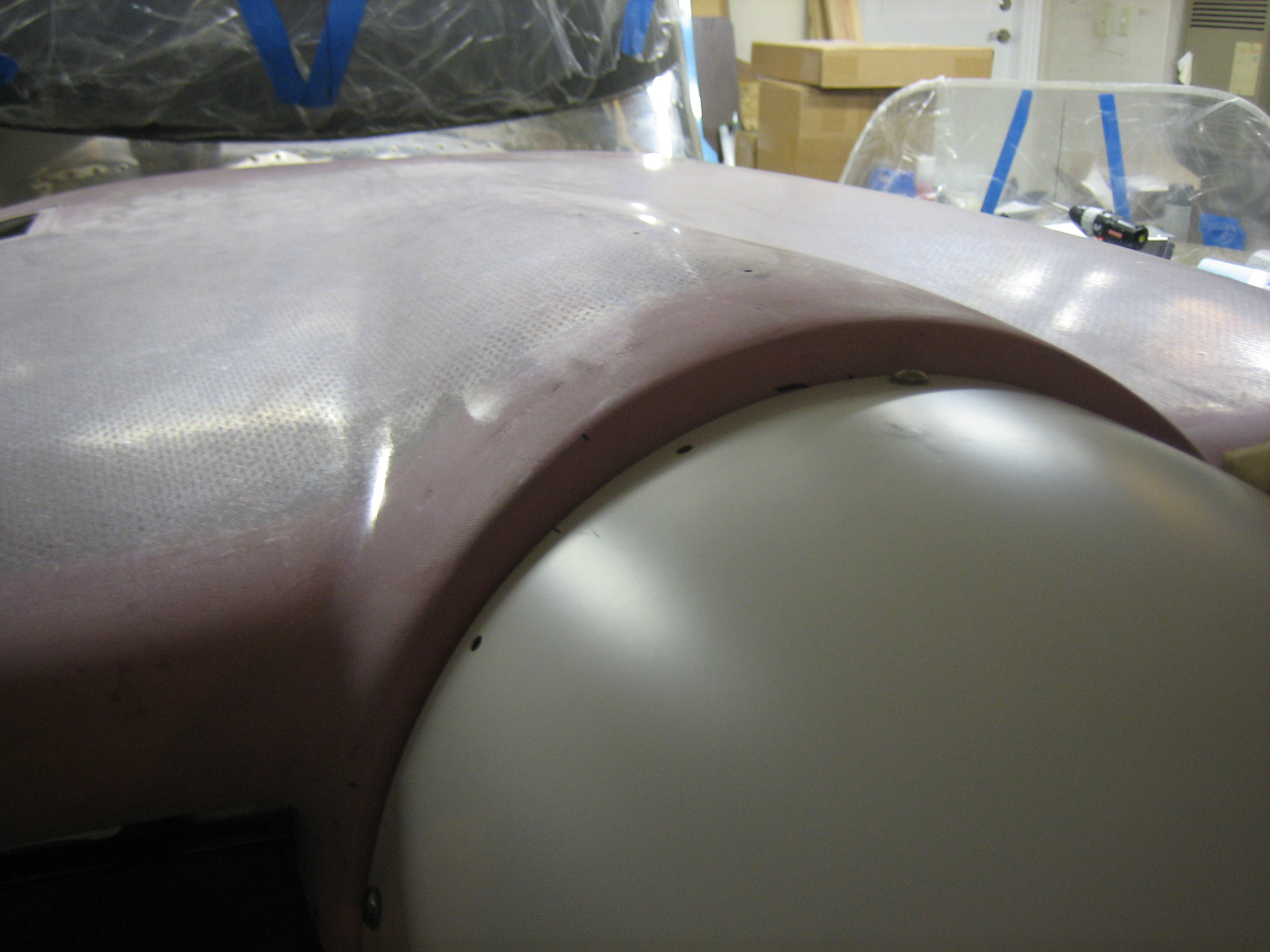
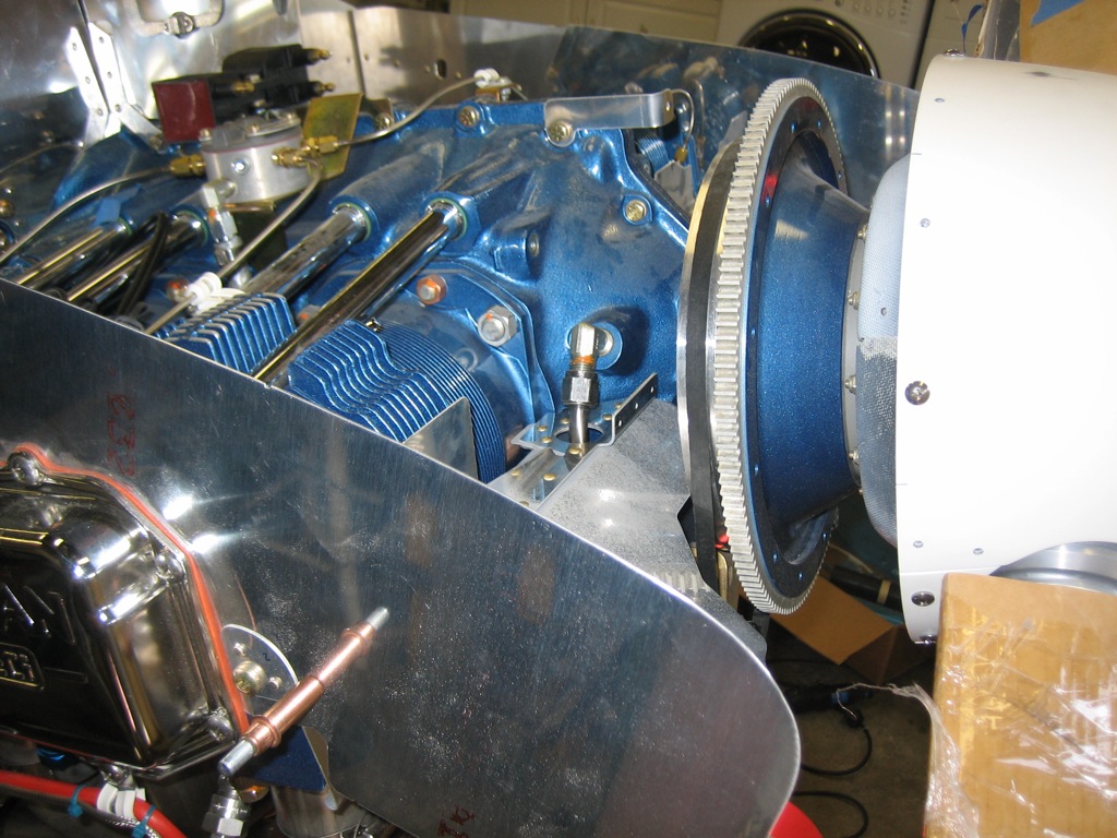
With a little trimming back of the side baffles, I got the cowl to fit down behind the spinner.  You can see that it’s still nearly 1″ too high, so I’m going to have to cut off quite a bit of material to get the cowl to drop all the way down and then further to have the necessary clearance between the cowl and the baffles.  The engine can move around quite a bit due to the flex of the engine mounts, and you don’t want the baffles to contact the cowl.

The standard way to trim the baffles is to line the top with paper clips and then put the cowl on top.  The cowl will push some paper clips down more than others. You can then measure down some amount from the top of each paper clip to create a cut line that perfectly follows the curvature of the inside of the cowl.

Trimming Baffles

No pictures tonight, but I went through a few iterations trimming the baffles.  The cowl is quite a bit lower, but still not all the way down.  I probably have at least 1/2″ to go if not more.

I also started trimming the ramps.  I have no idea why they give you so much extra material; you have to cut quite a bit of it off before you can even start bringing the lower cowl up into place.