Started Fitting Lower Cowl

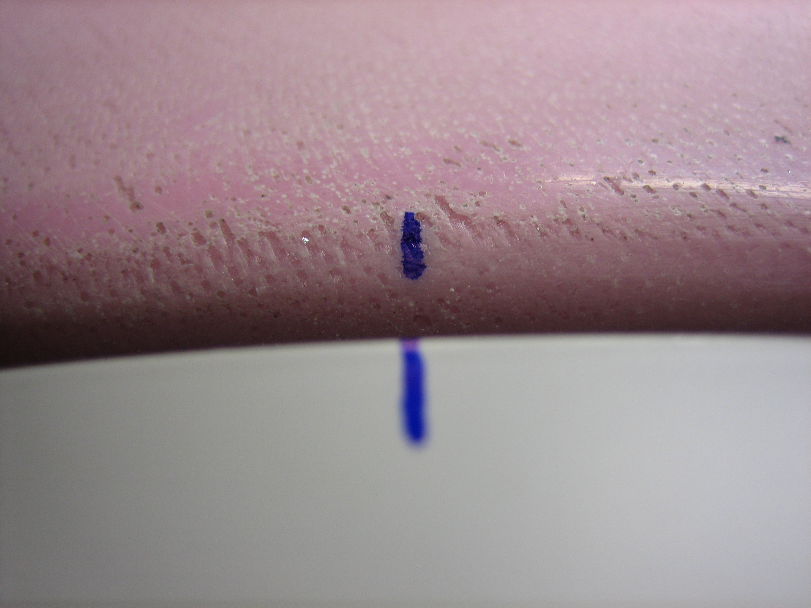
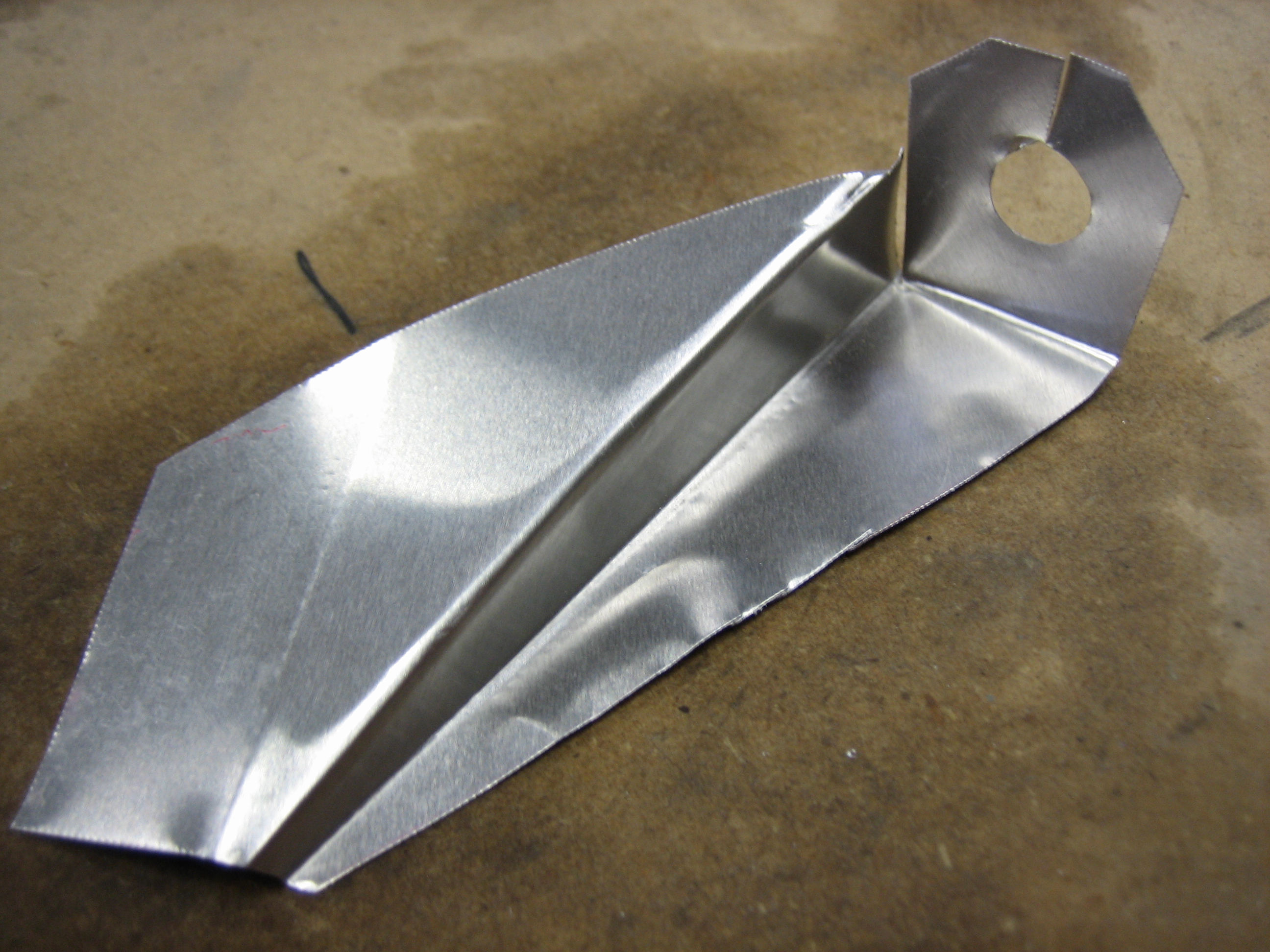
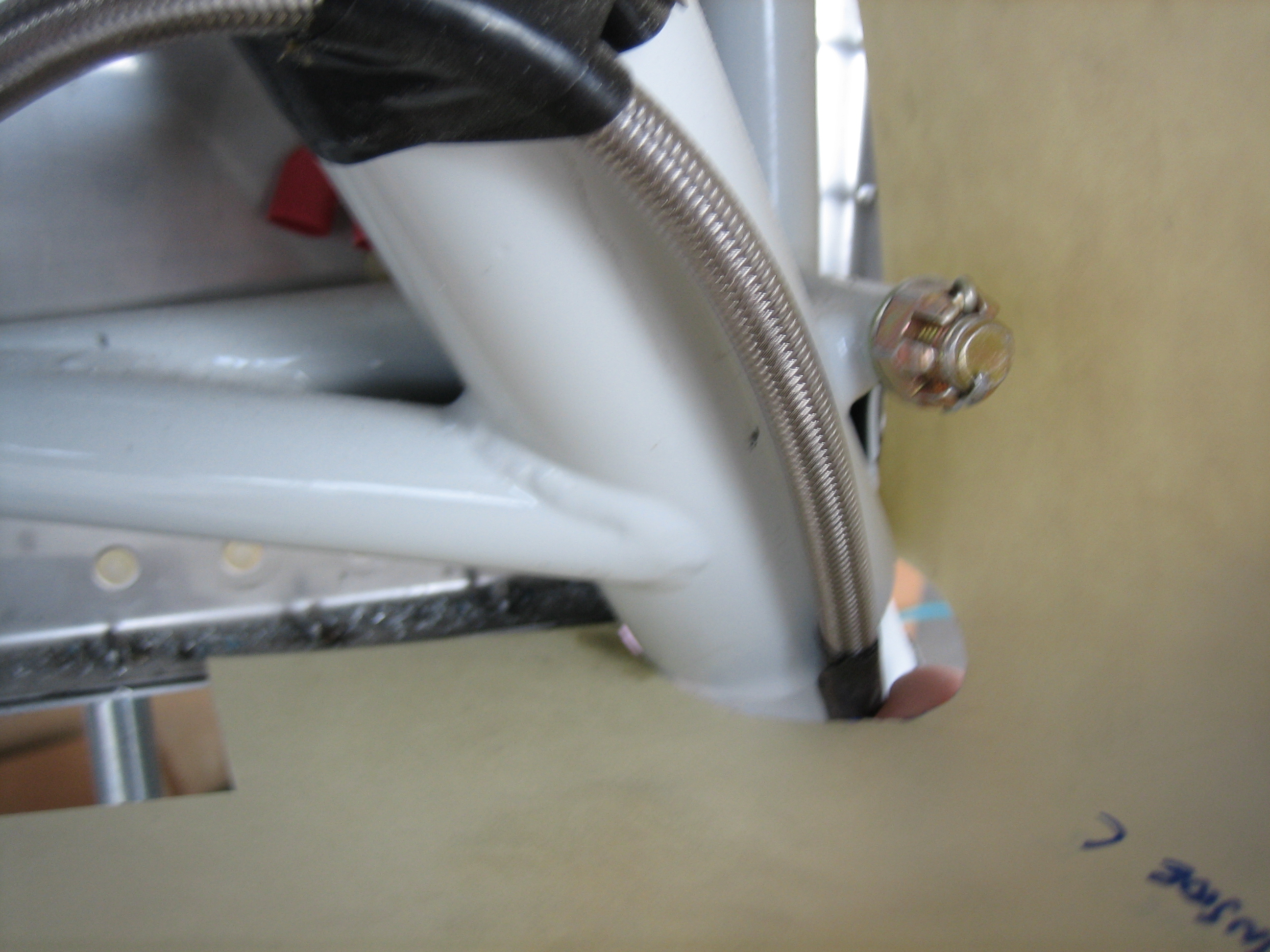
I finished adjusting the flange on the front to be perfectly round and then drilled a hole on each side to lock in the position.

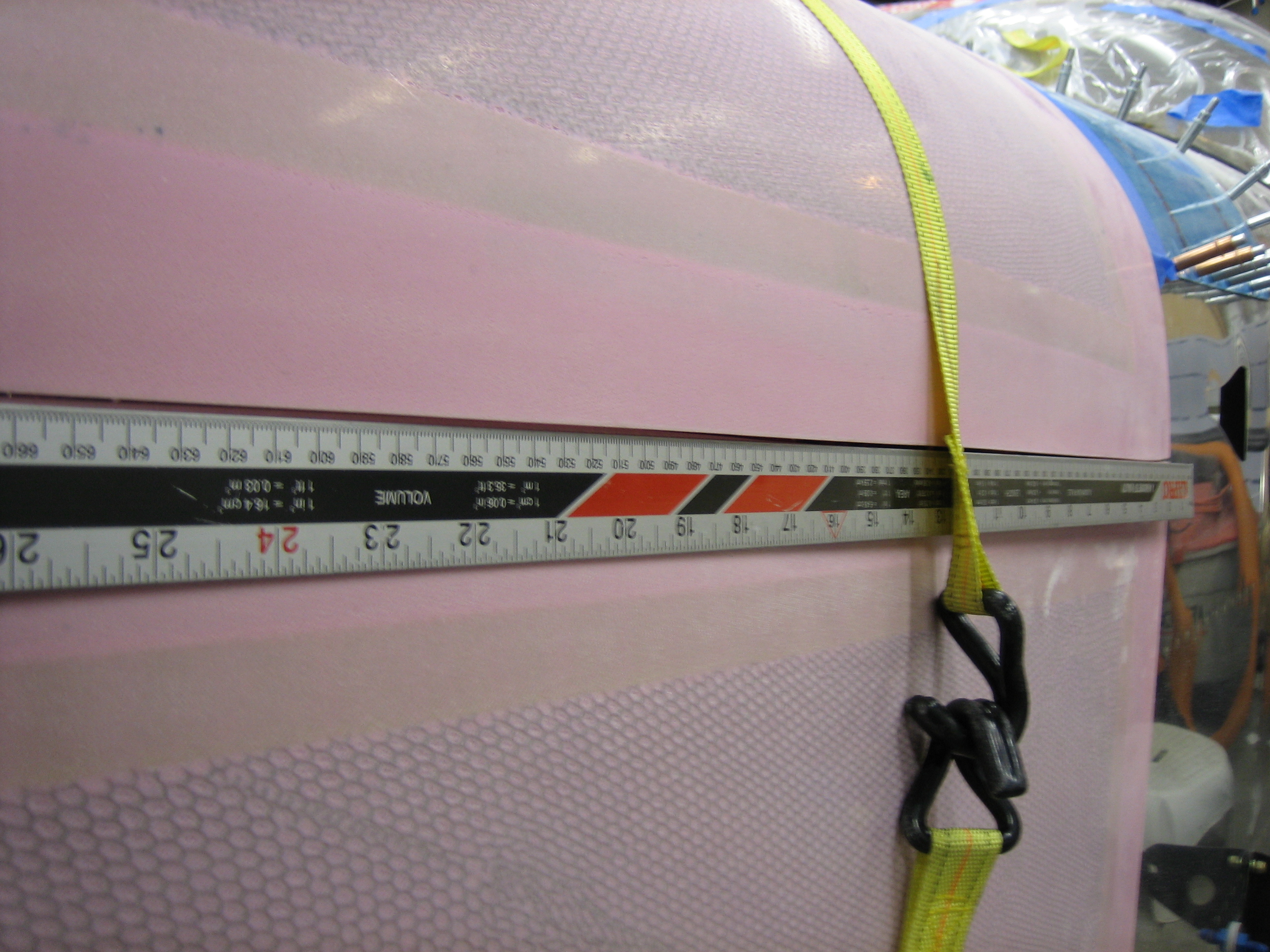
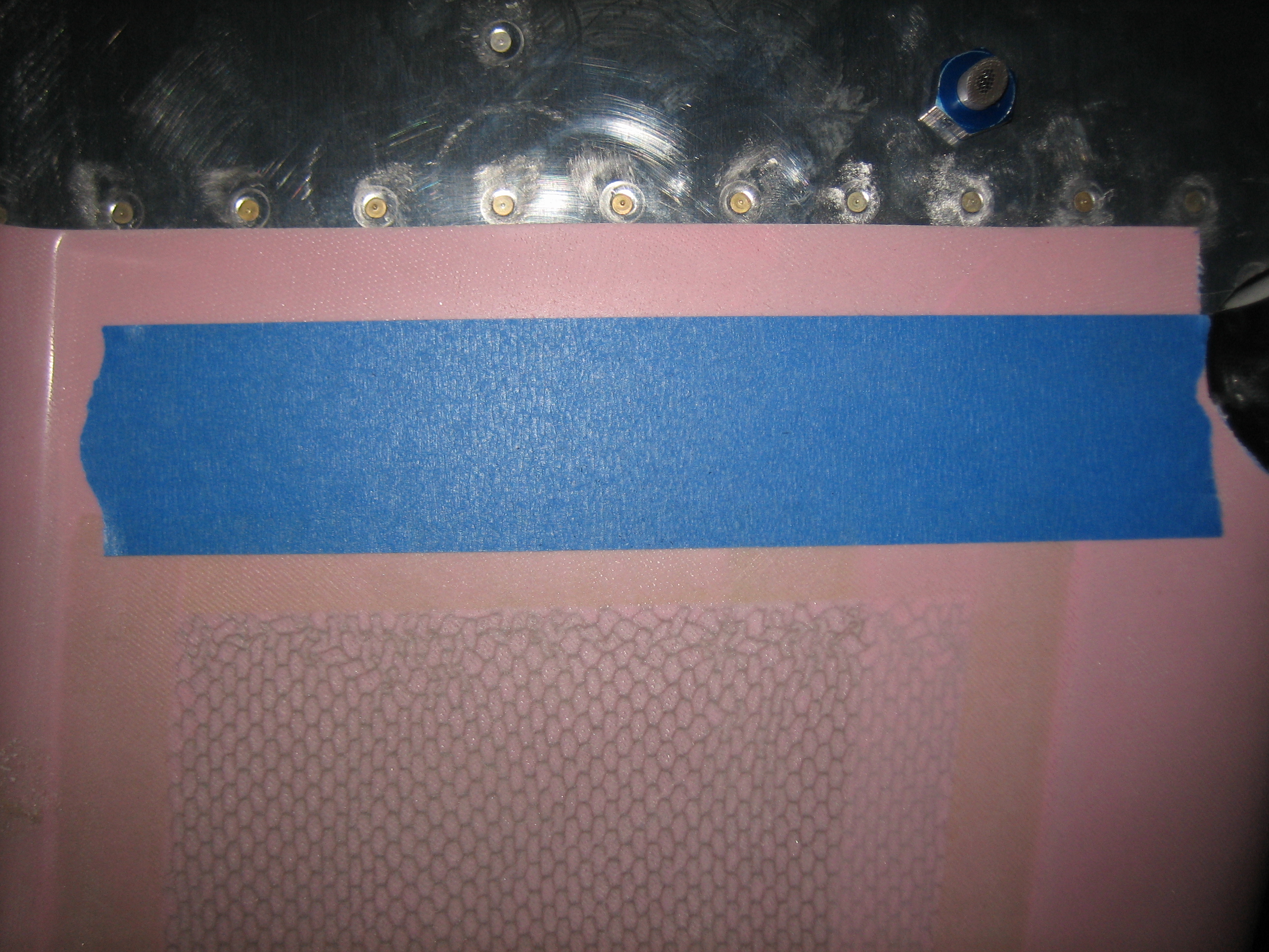
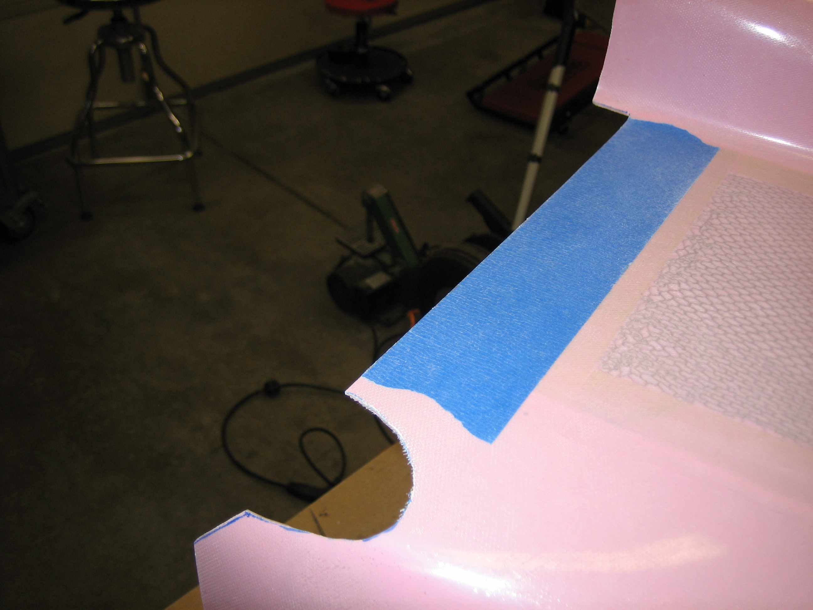
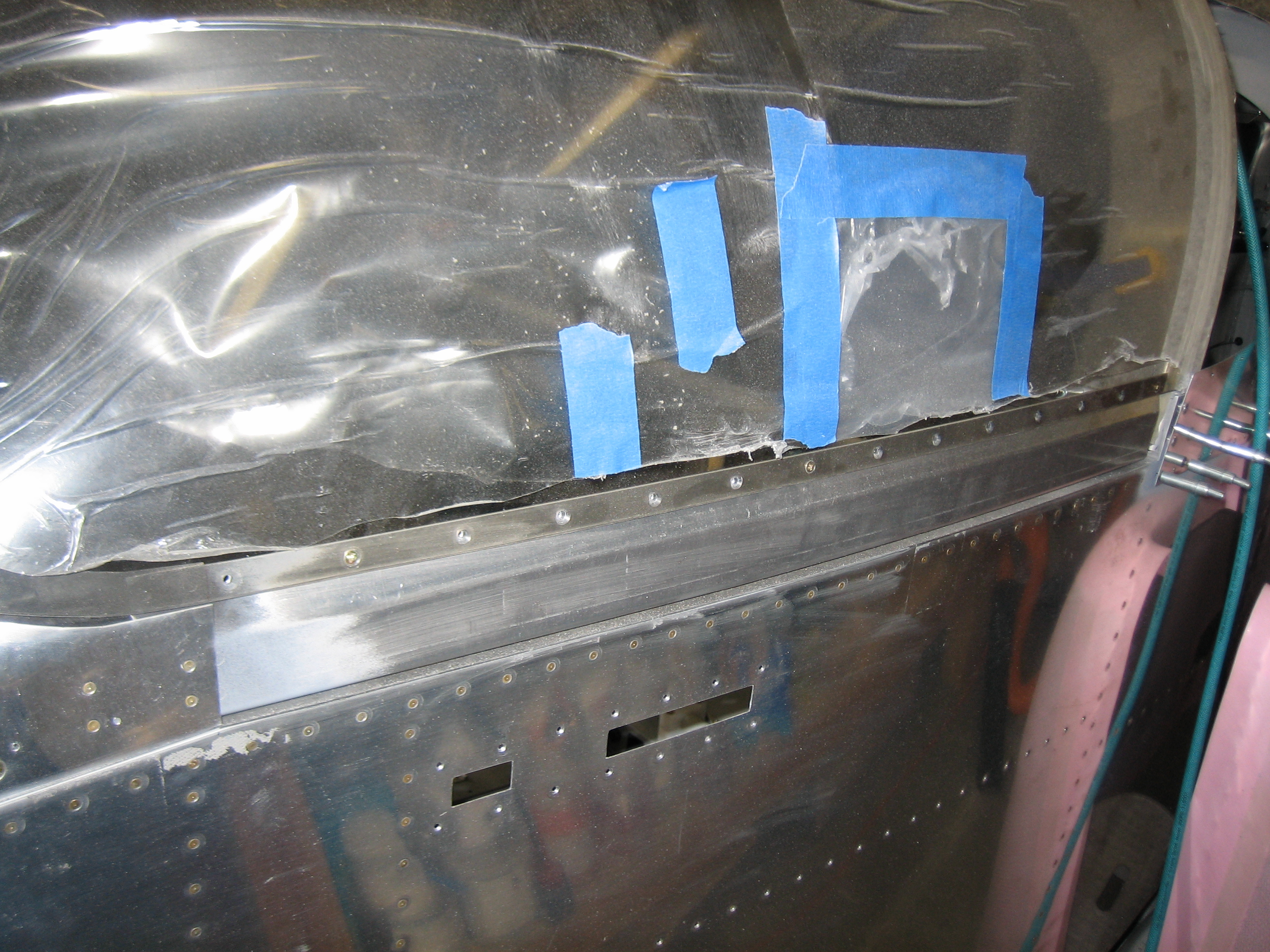
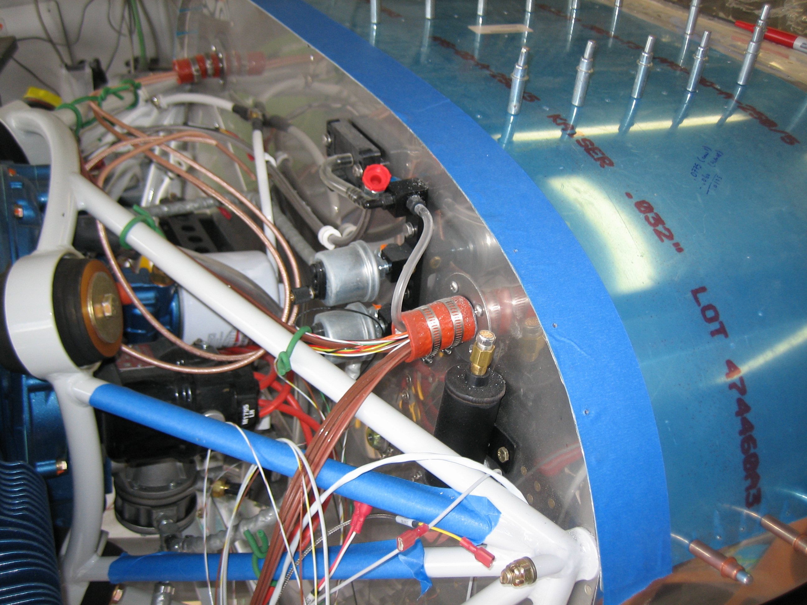
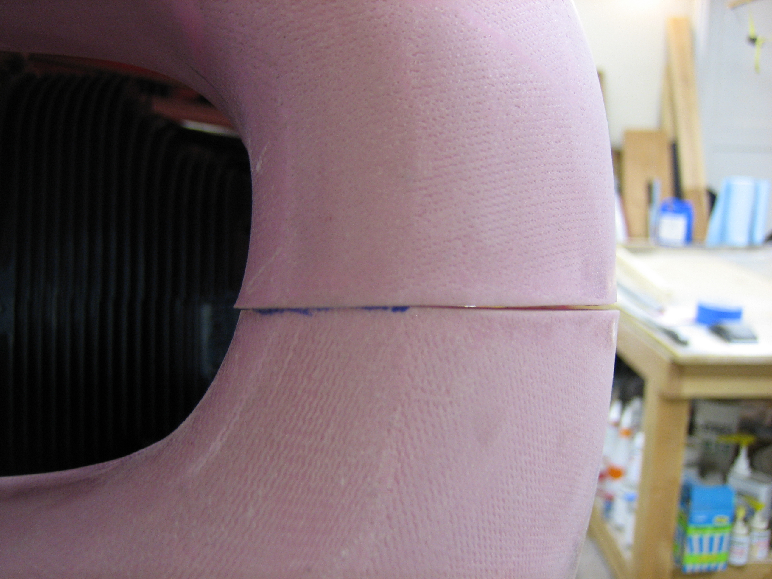
The plans specify that you mark a line 2″ aft of the firewall flange as a reference point for trimming.  As I’ve seen several other builders do, I used some 2″ wide painters tape.

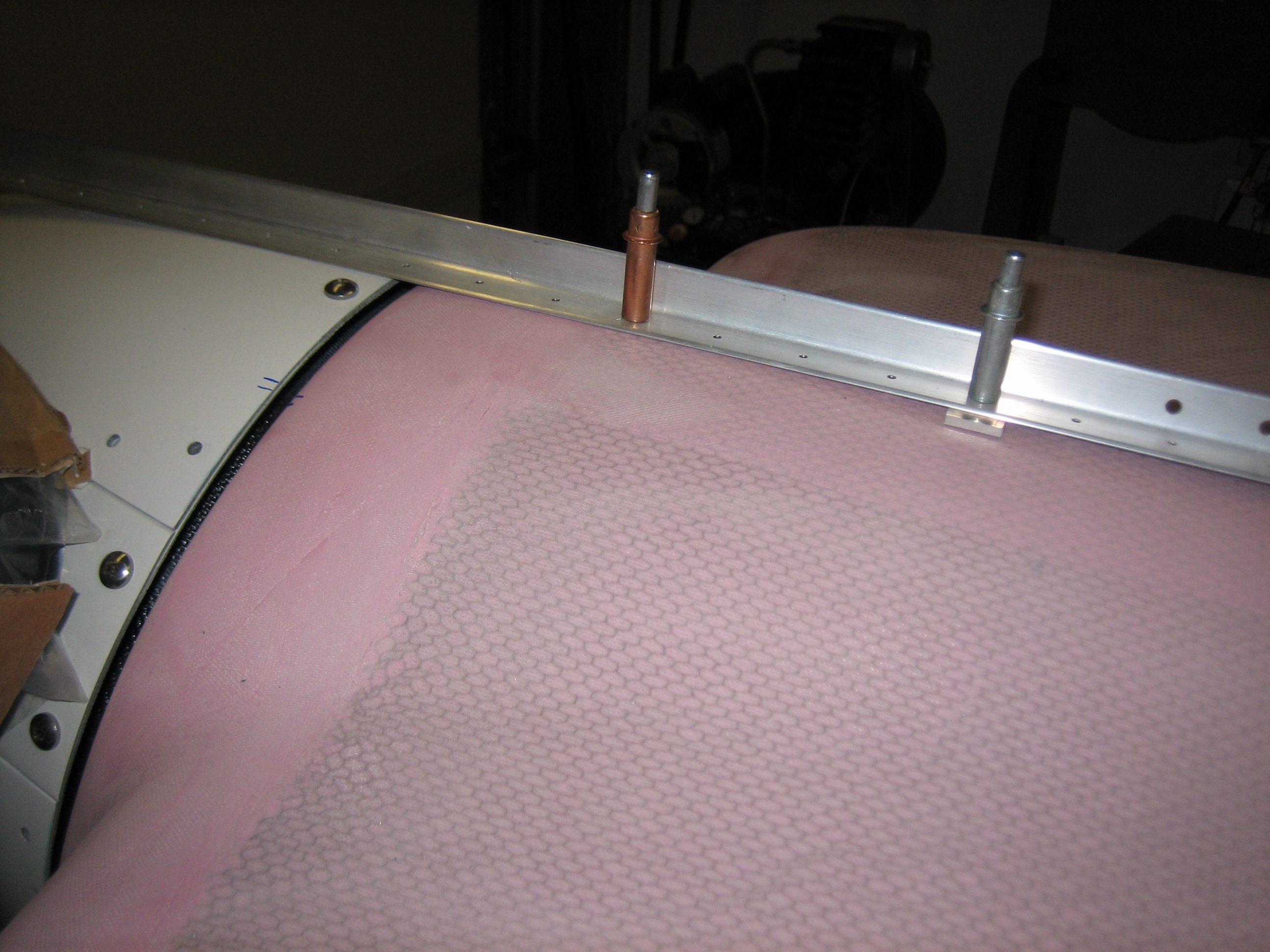
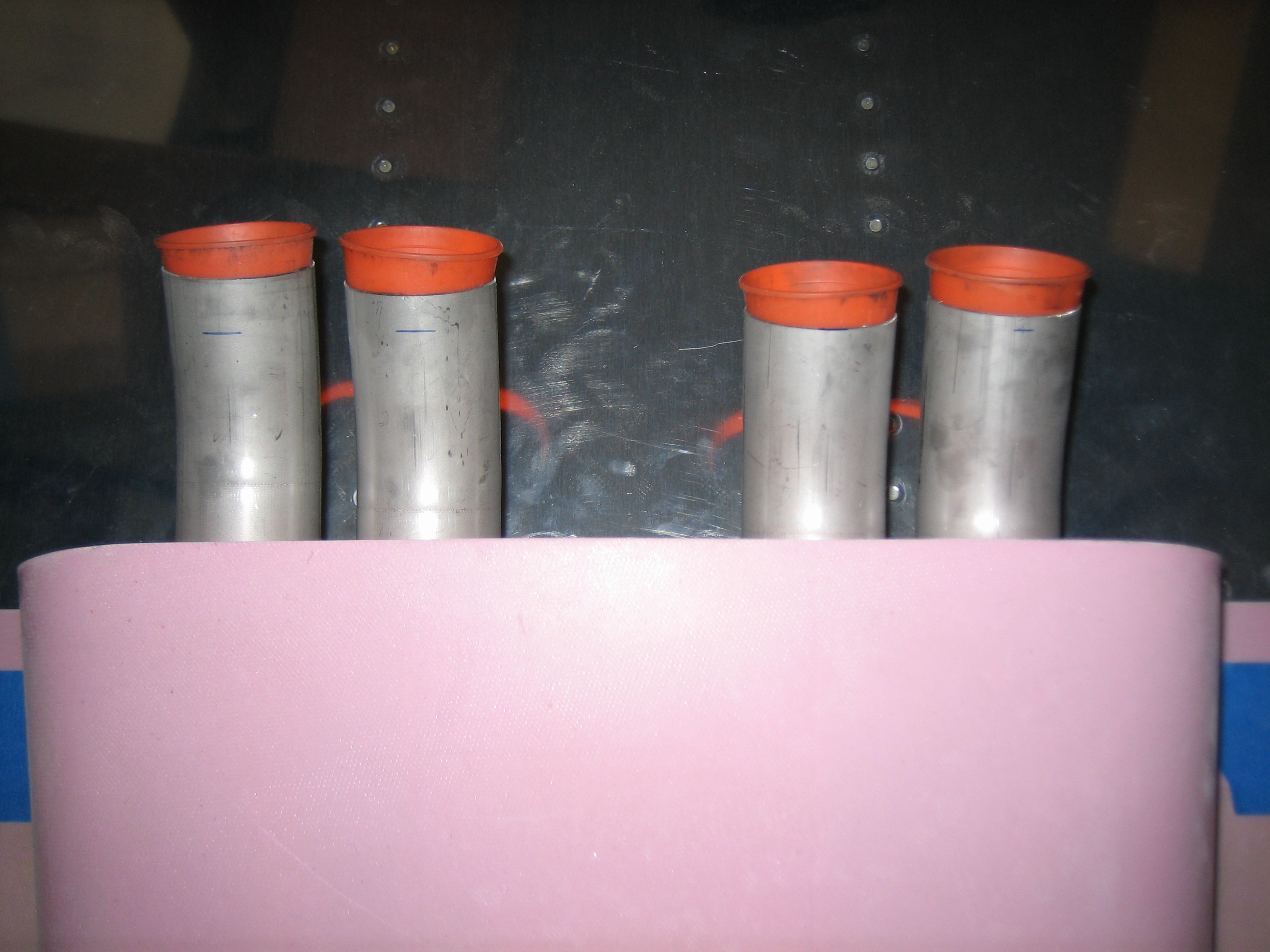
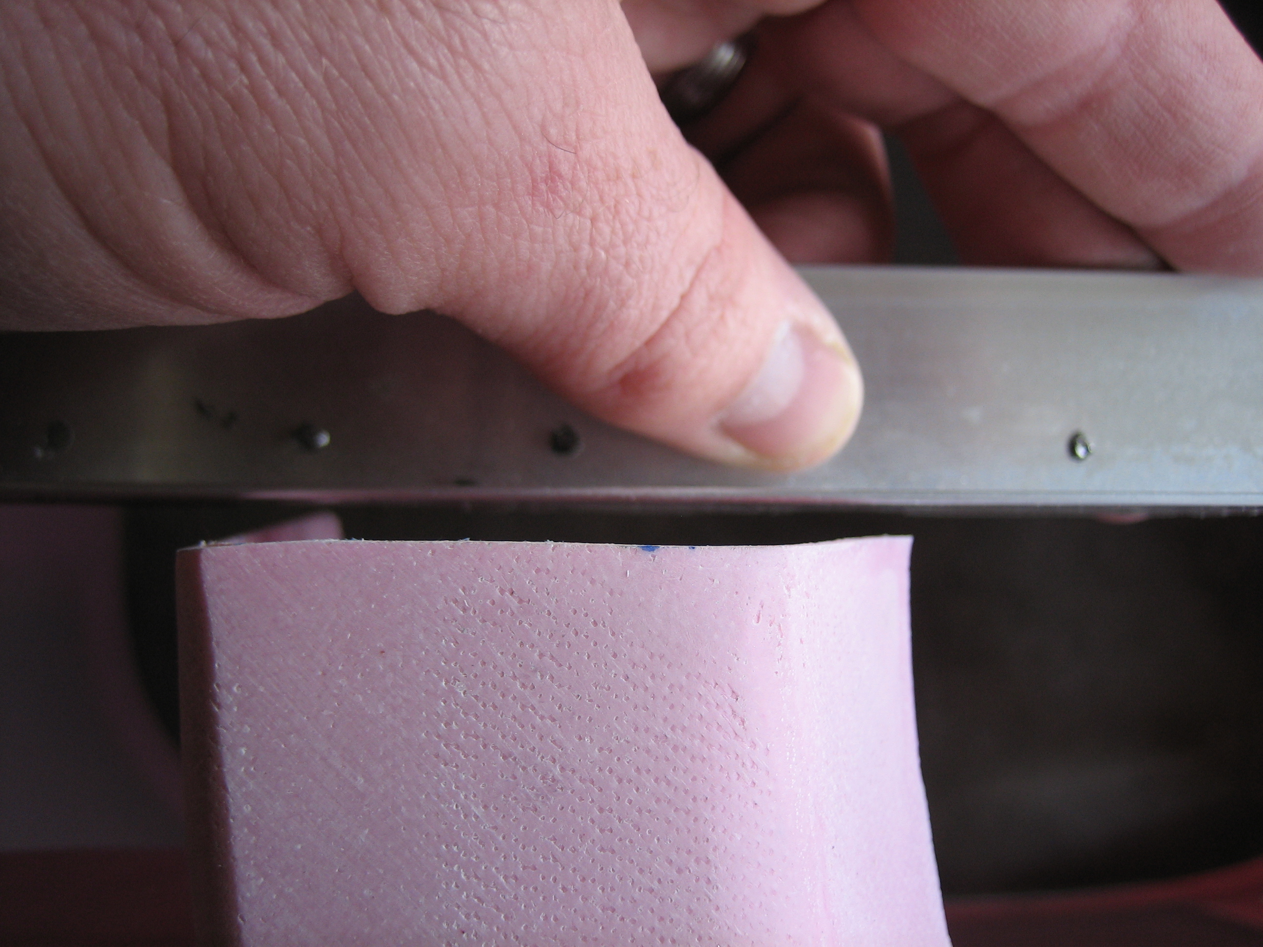
I laid a straightedge across the top cowl to see how the four flanges lined up.  Three were nicely in line…

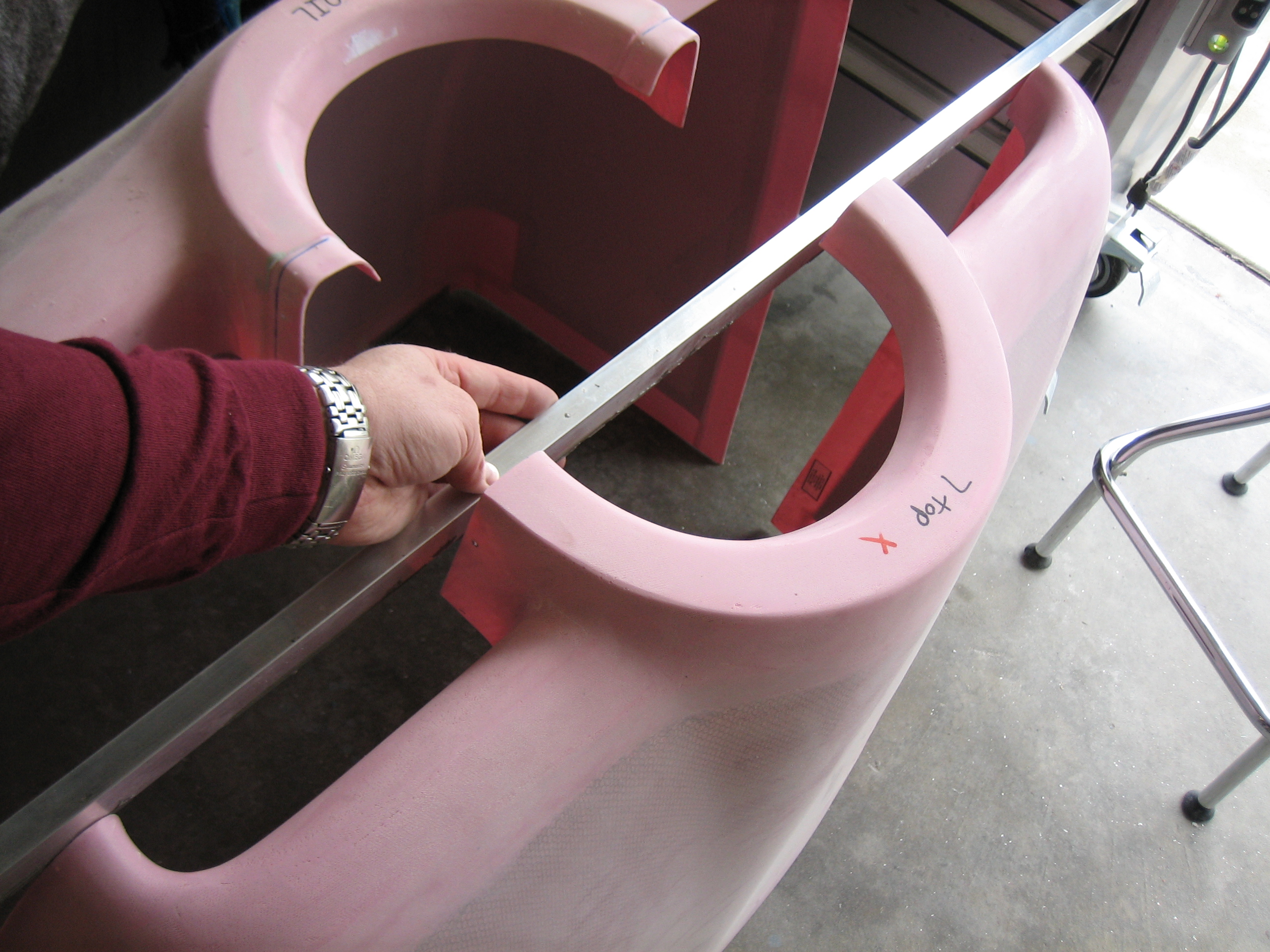
However, one of the flanges sits about 1/8″ shy of the line.

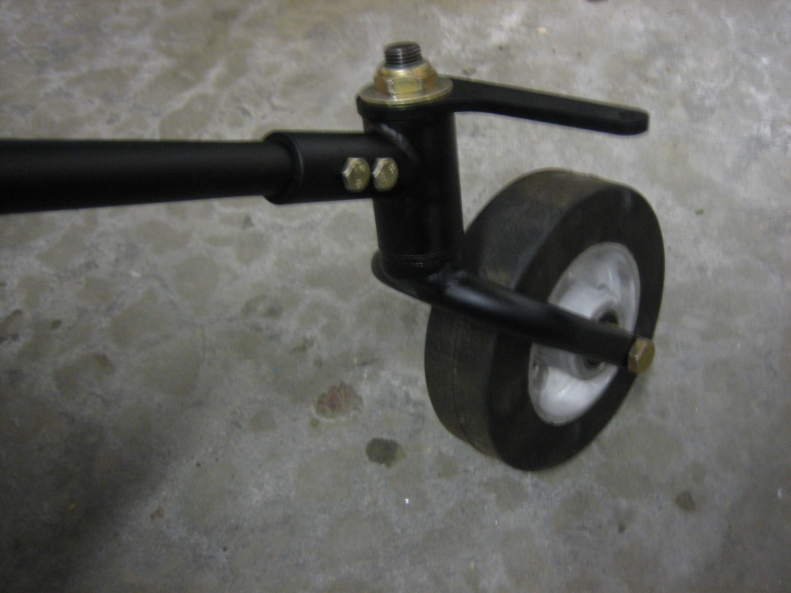
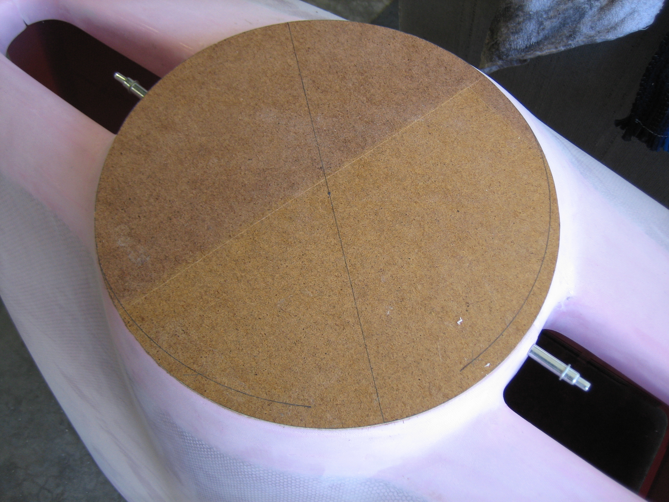
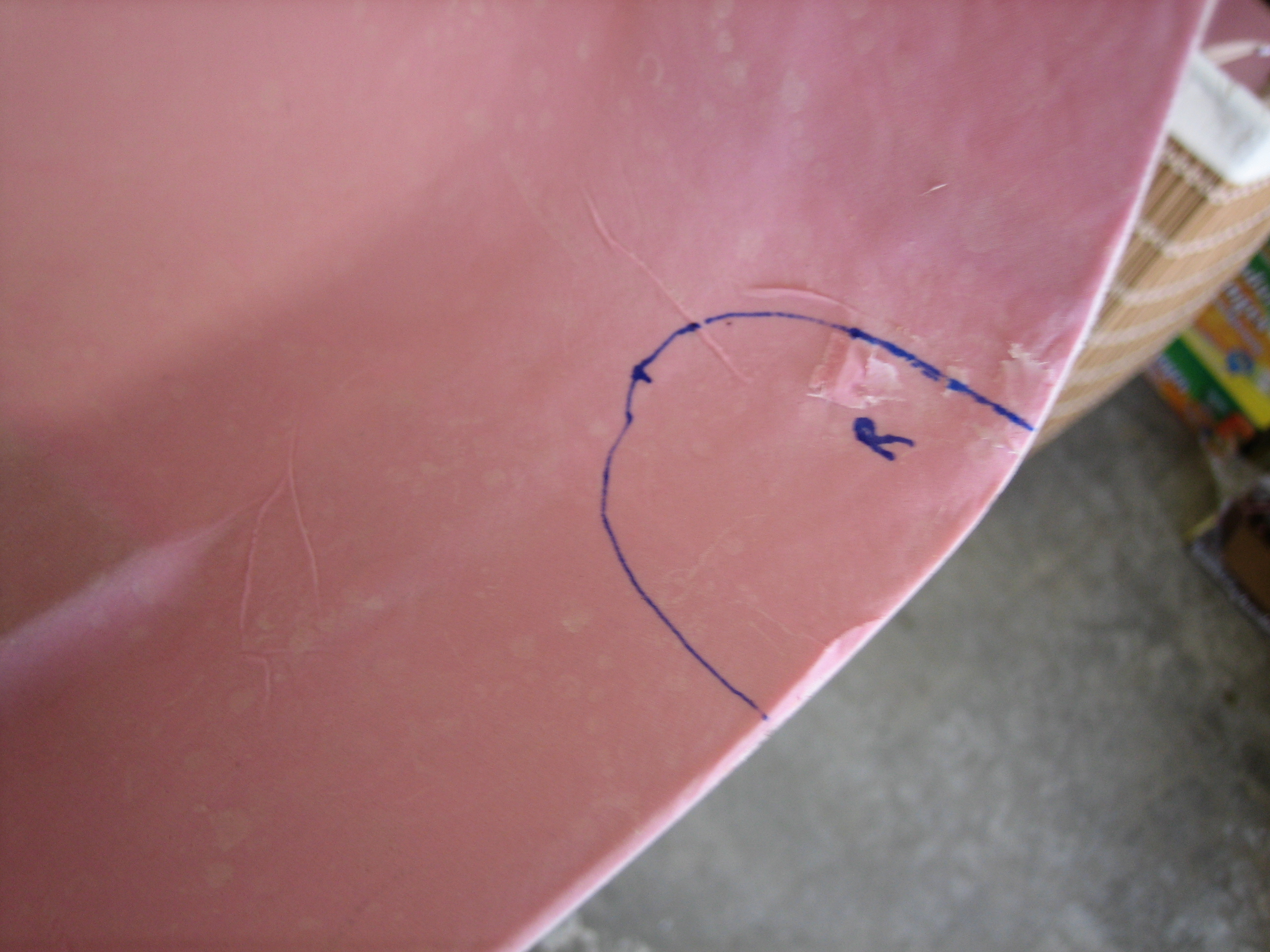
After doing a bunch of research on cowl fitting, I decided to fit the bottom cowl first.  I started by making a paper template for the gear let cutouts.

I transferred this to the cowl and then cut it out with the angle grinder.

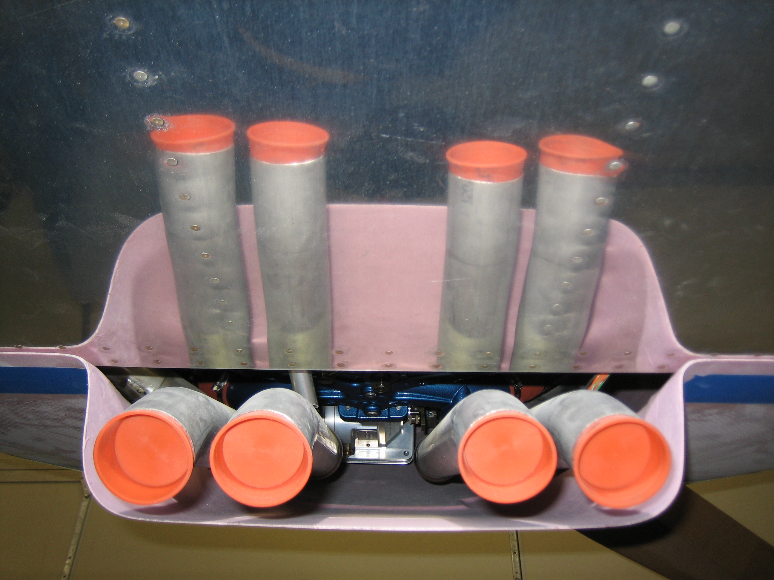
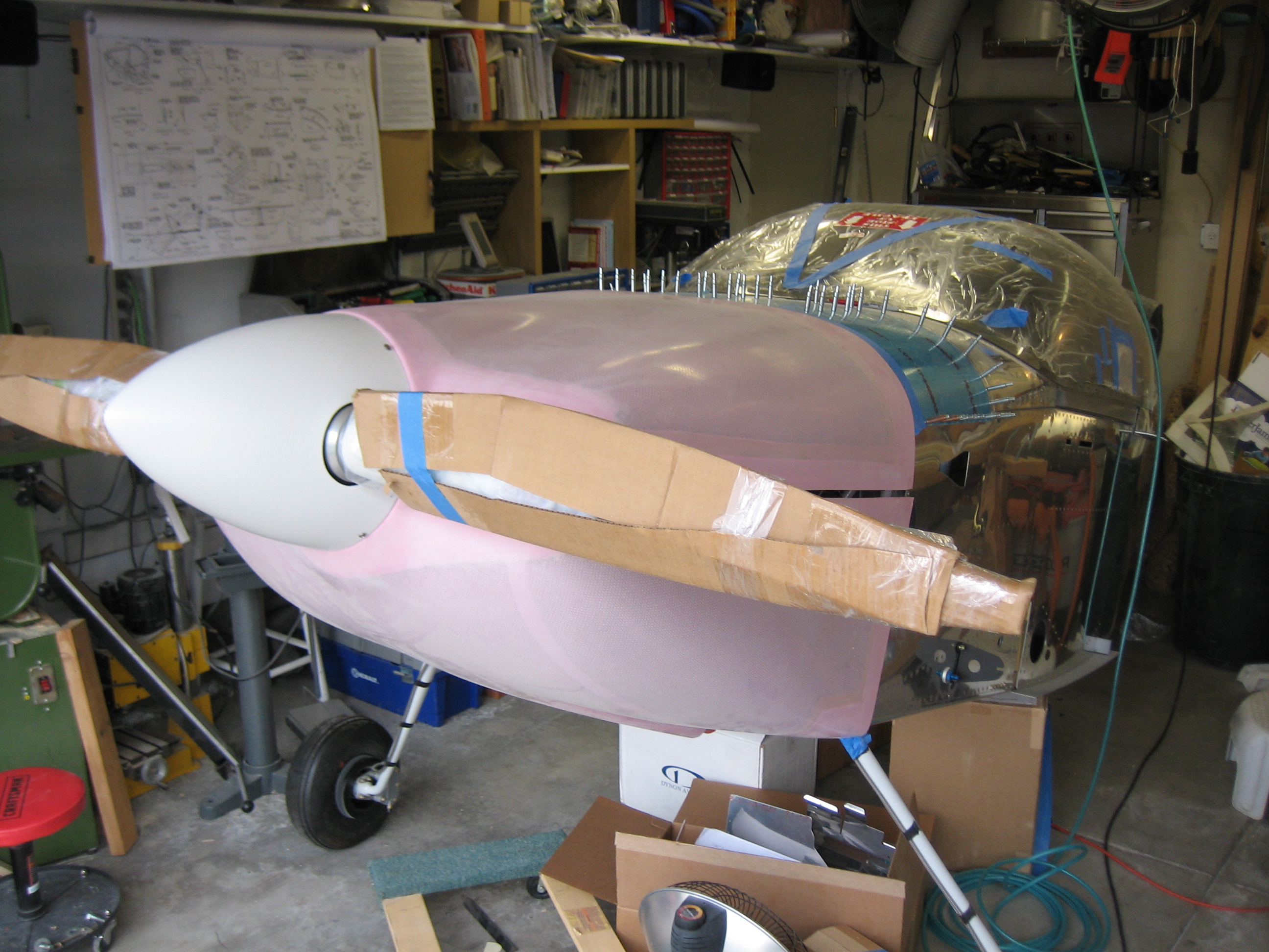
After loosely fitting the cowl halves, I just had to take a picture.  This is looking pretty damn sweet!

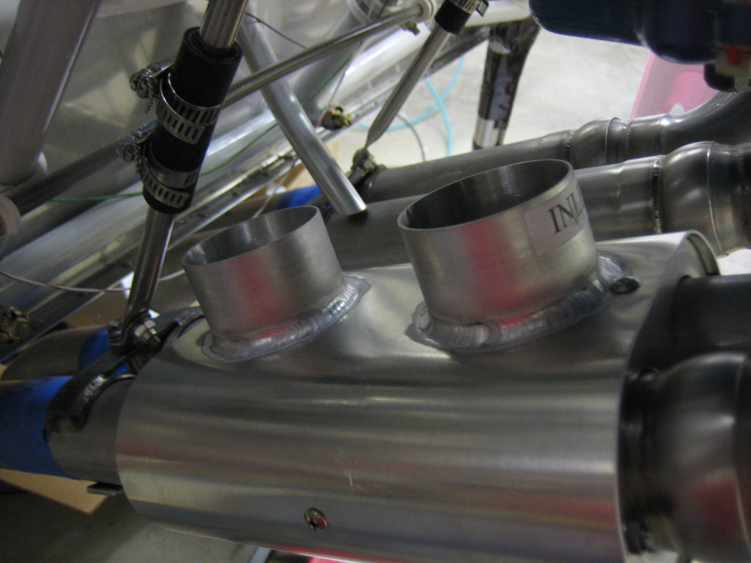
The flanges around the inlets needed a little trimming to get the joint tight.  This is pretty close.

After a little further trimming of the gear leg holes, the cowl halves fit together reasonably well.  There’s still a small gap down the side, but that should disappear after making the trims along the aft edges.

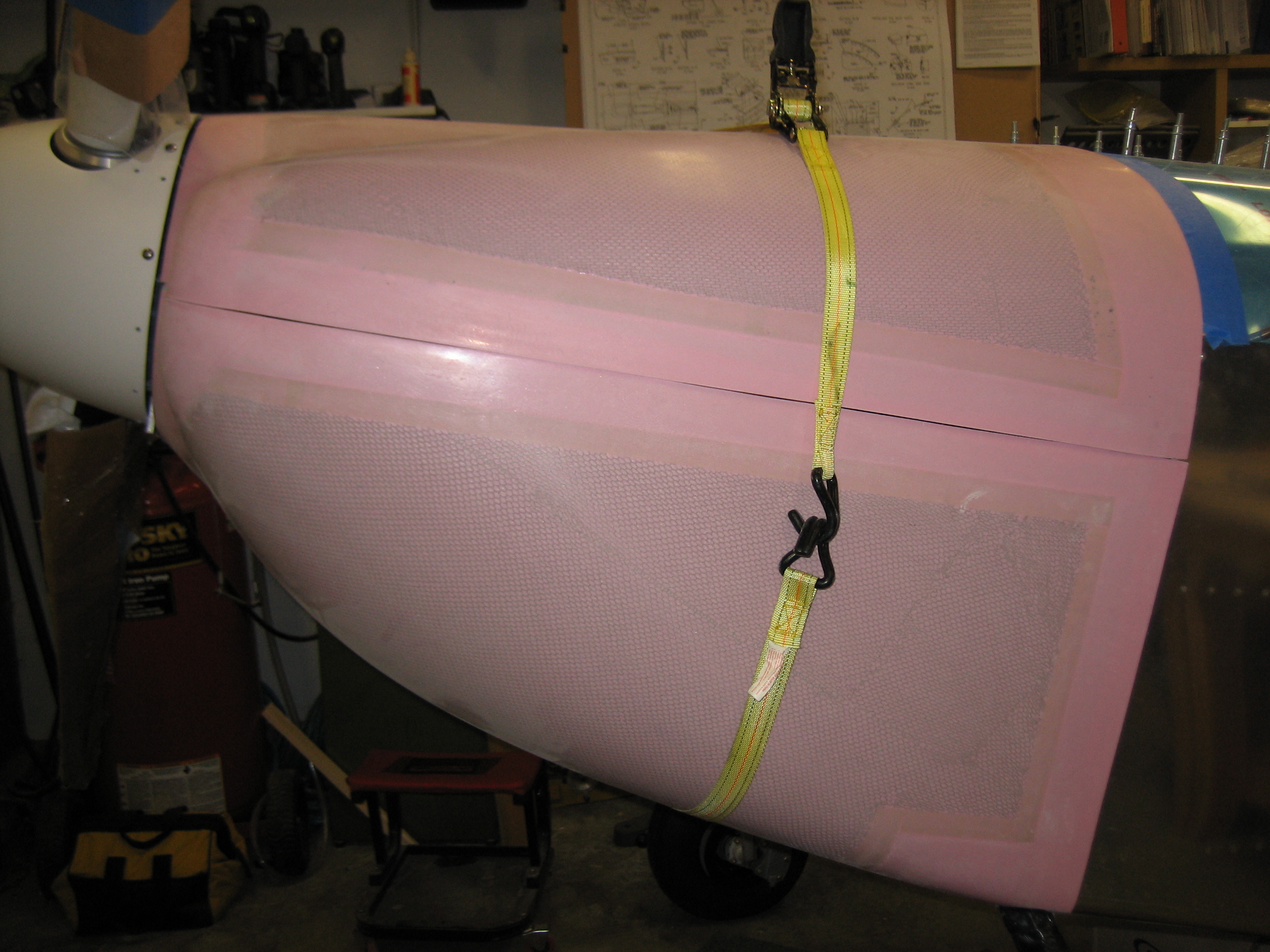
This is a problem though.  Even if the gap pulls tight, the joint along the right side isn’t remotely straight.  I can’t cut a straight line here because that would just make the gap even wider.  The instructions (as well as other builder’s websites) indicate that the sides should overlap during the trial fitting.  I’m starting to wonder if these pieces weren’t trimmed incorrectly at the factory.

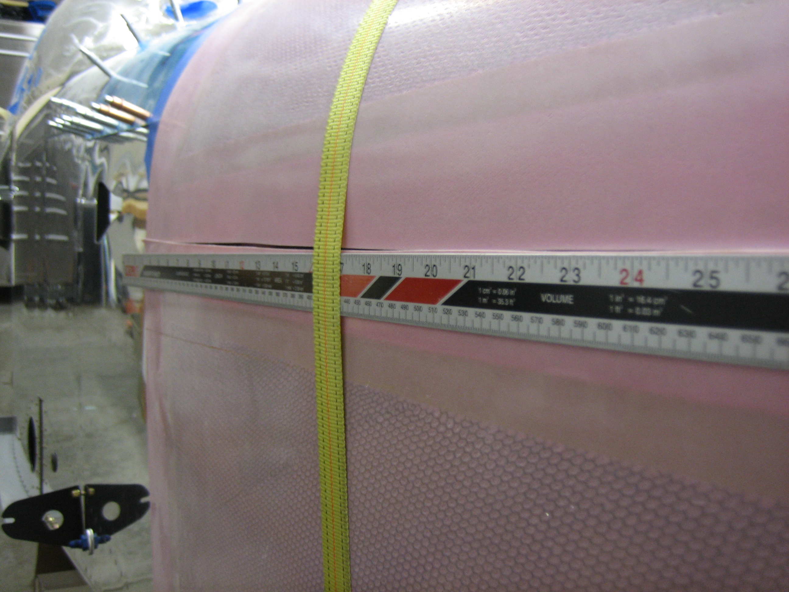
The joint on the left side is pretty close to straight though.  I’m going to email Van’s tech support and see why these flanges aren’t overlapping and what they suggest I do about it.

Finished Powder Coating Tailwheel Components

I re-powder-coated the part that didn’t come out right last week.  The problem turned out not to be lubricant leaking out between the steel and brass components.  In fact, I had simply not cleaned out all of the grease from the inside of the weldment.  When it heated up, it flowed out and ruined the finish.  I ground off all of the powder coat and cleaned it inside and out before redoing it tonight.  Afterward, I assembled all of the components.  This will stay on the shelf until the prop comes back off.

Fit Bottom Aft Edge of Cowl and Started Exhaust Brackets

In order to make sure the cowl returns to the same position each time, I drilled a piece of scrap aluminum angle to the top cowl so that it aligned with the spinner.  The clecos didn’t really hold in the fiberglass, so I ended up putting some scrap aluminum on the other side and using some wing-nut draw clecos to anchor this firmly.

I also made a series of marks around the spinner to serve as reference points.

With the cowl in its final location, I put a light inside the cowl and put some masking tape along the cut line.

I did the rough cut with the cutoff wheel to within about 1/16″ of the line. After putting the cowl on and off a few more times, I was able to iteratively trim the line with a vixen file so that these edges align with the firewall flange.  I’ll trim the exit once I’m happy with how everything is fitting.

While I had the cowl in its final position, I took the time to position all of the exhaust pipes so there was an even gap all around them.  Each pair of pipes will be clamped together and then everything is loosely anchored to the engine mount.  I also made some marks on the pipes that are even with the shortest pipe.  I’ll cut all of these so that all of the ends are even.

Here’s a shot showing how much clearance I have all around.  I have about an inch of clearance top and bottom and about two inches on each side.  The pipes look like they aren’t vertically aligned here, but that’s just because the lengths vary.

I drilled and installed the pipe clamps.  The bottom steel straps needed to be bent to conform to the pipes.

Worked on Exhaust Pipes

After exchanging a couple of emails with Joe Blank at Van’s, they determined that my lower cowl doesn’t have a long enough side flange.  They’re going to send me a new lower cowl, so I’m going to work on a few other things until then.

Since I marked the cut points on the exhaust pipes last night, I pulled the lower half of each pipe and cut the three longest pipes to match the shortest.  I then cleaned up the ends so that there were no burrs and reinstalled the pipes.

I then fabricated the exhaust hangers.  These are each comprised of two pieces of stainless steel tubing connected by a piece of rubber tubing.  I flared the ends of the stainless tubes so that they couldn’t slip out of the rubber tube.

Now that the exhaust is installed for good, I installed the heat muff around the #1 and #3 pipes.  This was a bitch to get on since the fit is really tight.  I moved it almost as far forward as possible so that I can get maximum heat transfer as well as provide the most room for the aft SCAT tube.  I could have moved it forward another 1/4″ or so, but I wanted to be able to inspect the weld on the #3 pipe during annuals.

Despite moving the heat muff forward, the right exhaust hanger is still going to interfere with the aft SCAT tube.  I’m going to have to shorten the exhaust hangers which will have the effect of moving the upper attach points farther out.  Hopefully that will give me enough clearance that the SCAT tube won’t rub on the exhaust hanger.

Misc Firewall Forward Work and Resumed Canopy

I remade the exhaust hangers so that I clearance to install the aft SCAT tube on the heat muff.  I ended up shortening each stainless tube by about 2″ or so and then re-flared the ends and reassembled each support.  Shortening these caused them to splay out more which is what provided the additional clearance for the SCAT tube.  Another advantage of this is that there is more lateral stability for the exhaust pipes.

Now that the exhaust pipes are in the final spot, I installed the adel clamp on the breather tube.

The lower end is positioned right over one of the exhaust pipes so that any oil blown overboard is burned off instead of coating the belly.

Since the cowl is on hold until I get a replacement lower half, I decided to finish off the canopy.  Next up is to fabricate the side skirts.  I installed a few screws on each side to hold the canopy against the canopy frame.  This had the unfortunate side effect of pushing out the frame so that the side skirts are no longer flush with fuselage sides.  I’ll have to gently flatten out the curve in the frame to pull the sides in a bit.

Since I was alone, I needed to be able to reach the screw on the outside and the nut on the inside at the same time.  My arms were long enough to reach the aft and middle screws, but I needed to fabricate a little tool to hold the nut while I turned the screw from the outside.

Since I cut the forward skin back a bit so that the joint lines up with the bend in the longerons, the included skirts aren’t long enough.  I used my air nibbler to cut some longer and narrower side skirts.  These are 2.75″ wide and about an inch longer that the included skirts.  Once these are fit to the canopy frame, I’ll trim the aft end to match the angle of the skin surrounding the rear window.

Drilled Canopy Side Skirts

I laid out the holes for one of the side skirts, then clamped them together and drilled both at the same time.  The plans show a uniform spacing for each row, but because the rivets are angled back at the aft end to follow the angle of the canopy frame, the plans show a slightly wider spacing for the upper row of rivets.  Instead, I laid out all of the rivets on a 1.5″ spacing except for the aft pair in the upper row which are about 1.7″ apart.  I also spent a little time trying to plan how I would fabricate the lift handle.  I’m leaning towards cutting a slot in the side frame and skirt and installing the angle from the inside.

Dynon SkyView Supports the Vertical Power VP-X!

Dynon and Vertical Power this morning announced that the SkyView system will be supporting the VP-X.  After seeing the VP-X at Oshkosh last year, I decided to defer working on the electrical system as long as possible in the hopes that this will happen.  Thanks guys; this combination is going to rock!

Here’s the announcement from Dynon:

http://www.dynonavionics.com/docs/news_VPX_announcement.html

It’s a little disappointing that they’re charging an additional $275 for this given that they’ll almost certainly sell more SkyView systems as a result and because every other avionics supplier is including it for free.  Dynon products are already priced much more aggressively than their competitors though, so I’m not going to complain too loudly.

Here’s an overview of the VP-X:

http://verticalpower.com/vp-x/

After working through the load planning, I’ll be going with the VP-X Pro.  Using the VP-X should not only simplify wiring, it should provide substantial new features to the electrical system as well as advanced fault detection.

Now, if Garmin would just announce a replacement for the GNS-430…

Installed Exhaust Stabilizer Strap

I installed the exhaust stabilizer strap that ties the two pairs of exhaust pipes together.  This significantly stabilizes the exhaust pipes over just having each pair supported by on hanger.

Construction work is slowing down on the plane a bit while I’m working on the electrical system design.  The VP-X is fairly significantly different than the architecture specified in the Aeroelectric Connection.  I’m reworking most of the schematics and still trying to decide how I’m going to handle backup circuits for several devices.

Prototyped Throttle Bracket

The stock throttle bracket that Van’s supplies doesn’t work with the Superior sump since the attach point is in a different location.  I’m going to fabricate a custom bracket out of some 16 gauge steel (the same thickness as Van’s bracket).  I used some really thin (0.004″) aluminum flashing I had on hand to mock up the bracket.  This puts the cable on a direct path to the hole in the firewall and keeps it well clear of the exhaust and sump.

Here’s a shot from slightly lower in case that makes it more clear.

Here’s what the rough bracket looks like.  I unfolded this and traced the pattern onto some 16 gauge stock I picked up from Home Depot.  Cutting it out will be easy, but I’m still not quite sure how I’m going to bend this.